US2932088A - Programing apparatus for machine tools - Google Patents
Programing apparatus for machine tools Download PDFInfo
- Publication number
- US2932088A US2932088A US656322A US65632257A US2932088A US 2932088 A US2932088 A US 2932088A US 656322 A US656322 A US 656322A US 65632257 A US65632257 A US 65632257A US 2932088 A US2932088 A US 2932088A
- Authority
- US
- United States
- Prior art keywords
- dial
- rods
- inch
- positioning
- measuring
- Prior art date
- Legal status (The legal status is an assumption and is not a legal conclusion. Google has not performed a legal analysis and makes no representation as to the accuracy of the status listed.)
- Expired - Lifetime
Links
Images


Classifications
-
- B—PERFORMING OPERATIONS; TRANSPORTING
- B23—MACHINE TOOLS; METAL-WORKING NOT OTHERWISE PROVIDED FOR
- B23Q—DETAILS, COMPONENTS, OR ACCESSORIES FOR MACHINE TOOLS, e.g. ARRANGEMENTS FOR COPYING OR CONTROLLING; MACHINE TOOLS IN GENERAL CHARACTERISED BY THE CONSTRUCTION OF PARTICULAR DETAILS OR COMPONENTS; COMBINATIONS OR ASSOCIATIONS OF METAL-WORKING MACHINES, NOT DIRECTED TO A PARTICULAR RESULT
- B23Q16/00—Equipment for precise positioning of tool or work into particular locations not otherwise provided for
- B23Q16/004—Equipment for precise positioning of tool or work into particular locations not otherwise provided for positioning by combining gauges of different dimensions from a set of two or more gauges
-
- G—PHYSICS
- G05—CONTROLLING; REGULATING
- G05B—CONTROL OR REGULATING SYSTEMS IN GENERAL; FUNCTIONAL ELEMENTS OF SUCH SYSTEMS; MONITORING OR TESTING ARRANGEMENTS FOR SUCH SYSTEMS OR ELEMENTS
- G05B19/00—Program-control systems
- G05B19/02—Program-control systems electric
- G05B19/04—Program control other than numerical control, i.e. in sequence controllers or logic controllers
- G05B19/0405—Program-control specially adapted for machine tool control and not otherwise provided for
-
- Y—GENERAL TAGGING OF NEW TECHNOLOGICAL DEVELOPMENTS; GENERAL TAGGING OF CROSS-SECTIONAL TECHNOLOGIES SPANNING OVER SEVERAL SECTIONS OF THE IPC; TECHNICAL SUBJECTS COVERED BY FORMER USPC CROSS-REFERENCE ART COLLECTIONS [XRACs] AND DIGESTS
- Y10—TECHNICAL SUBJECTS COVERED BY FORMER USPC
- Y10T—TECHNICAL SUBJECTS COVERED BY FORMER US CLASSIFICATION
- Y10T408/00—Cutting by use of rotating axially moving tool
- Y10T408/08—Cutting by use of rotating axially moving tool with means to regulate operation by use of templet, tape, card, or other replaceable information supply
Definitions
- M f L and l I) v I 5 7 3 -zs1 7 we, 1 -70 m 15 a C m l, INVENTOR.
- This invention relates to a programing apparatus which regulates the motions and positions of a shiftable machine tool element so as to provide a sequence of machining operations at preselected locations on a workpiece in response to coded record media which is fed into the programing apparatus.
- a primary objective of the invention has been to provide for the rapid and precise positioning of the shiftable machine element, such as a table or slide, utilizing selective lineal measuring rods or gauges which are shifted in response to the programing apparatus into alignment with one another, such that the additive length of the measuring rods, establishes precisely the preselected locations of the shiftable element.
- the programing apparatus is disclosed in relation to a jig boring machine which is utilized in' the precise centering and machining of holes.
- the conventional jig boring machine is intended primarily for the boring of jigs and the like, the hole centers being located with an exceptionally high degree of precision.
- the jig boring machine ordinarily isnot used in production work since each hole is located by gauge rods which are placed in the machine by hand, often incombination with adjustable micrometer gauges. The setting up and adjustment of the machine in this manner requires the services of a skilled machinist and consumes a great deal of time.
- a conventional jig boring machine comprises a bed having a vertical column having a rotating tool spindle whichis shiftable along a vertical axis relative to the bed.
- a work table is slidably mounted upon jf tes Patent j a cross slide or saddle for longitudinal motion relative to the saddle, and the saddle is shiftable transversely with respect to the bed of the machine, The work, which is clamped to the table, is located relativeto the spindle by the coordinated transverse and longitudinal movements of the saddle and table.
- the conventional measuring rods referred to above, are utilized for positioning the saddle transversely and for positioning the table lineal multiples of ten inches, a second group graduated in increments of one-inch, and a third group graduated in decimal increments.
- the decimal rods comprise four sets, each set having graduated lengths in the order of tenths, hundredths, thousandths, and ten-thousandths of an inch.
- a ten-inch dial is arranged to select the teninch rods, a one-inch dial provides selection of the one- 2 inchrods, and an individual dial shifts each set of decimal rods.
- the dials shift their respective measuring rods to active measuring position as the dials are rotated to bring their graduations to a reading position.
- one dial housing is mounted relative to the table for governing the table position and a second dial housing is mounted relative to the saddle for governing the saddle position.
- the two sets of dials are roa tated to the desired setting, thus providing the transverse and longitudinal coordinates for locating the hole center.
- This measuring apparatus provides the same order of precision as the conventional measuring rods which must be selected and adjusted by hand.
- the dial-controlled measuring apparatus of the cm pending application is intended particularly to be used in combination with the automatic positioning apparatus disclosed in Patent No. 2,674,706 to Robert N. Knosp et al.
- the positioning apparatus of the patent includes a control system having a spring-loaded feeler rod which governs the operation of a traverse motor and positioning motor.
- the traverse motor shifts the table toward the left or right at a rapid traverse rate, and the positioning motor shifts the table at a slow positioning rate toward the right to a final position, at which point the-feeler rod decommissions the motor and stops the table precisely at its final position.
- the traverse motor is energized by manual switches to shift the table to the leftaway from the measuring rod housing, the dials are rotated by hand to the selected dimension, then; the positioning cycle is initiated by depressing a manual cycle switch.
- the rods, Which'are shifted to measuring position, reside inalignment between a table abutment and the feeler rod; hence, the table causes the measuring rods to be shifted into endwise contact with the feeler rod to stop the table at final position in response to pressure imposed upon the feeler rod.
- the programing apparatus thereafter selects-the dimensions and causesthe table to be positioned auto. matically to the selected positions.
- the coded record may contain the dimensions for a complete pattern of holes for a given workpiece, causing the programing-apparatus to carry out the entire series of operations for each workpiece which'is clamped upon the table so as to provide exact duplicates.
- the apparatus accordingly carries forward the concept of dial selection andprecise automatic positioning and provides COOIdi'. nated cycling in a rapid automatic manner. As a result, one'or more machines may be operated by an unskilled worker in the rapid production of precision parts which may require boring of a complex pattern of holes.
- the programing apparatus comprises a dial selector mechanism which includes a set of dialdriving gears. arranged to rotate the dials of the measuring apparatus to preselected positions. Rotation of the gears in turn is regulated by respective electrical selector devices which-are actuated by the gears and which stoputhe gears when the dial reaches a selectedjdigit graduation, with the corresponding measuring rod shifted to measuring position.
- the dials of the measuring apparatus are also referred to as matrix members and the electrical selector devices are referred to as emitters.
- the programing apparatus includes a reader or signal generator which scans the printed record, such as a punched card having patterns of holes, each pattern representing a preselected dimension.
- the signals from the reader are fed into a program circuit which provides controlled cyclic operation.
- the program circuit is also interconnected with the circuit of the positioning apparatus to initiate an automatic positioning cycle in sequence with the dial selections.
- the cycles of the programing apparatus are initiated manually by depressing a switch.
- the program. circuit signals the positioning apparatus, which in turn traverses the table to the left a sufficient distance to permit insertion to the preselected measuring rods to their measuring position.
- This back-off position is regulated by a series of stationing switches which are energized by the circuit in accordance with the dimension signalled by the reader.
- the program circuit rotates the dial driving gears, causing the gears to rotate the dials or matrix members from random stationary positions forwardly to their selected positions and to actuate their electrical selector devices.
- the program circuit again signals the positioning apparatus and this time causes anautomatic positioning cycle to be initiated.
- the positioning apparatus carries out its own cycle once it receives the signal and thereby shifts the table toward the right to its final position with the feeler rod depressed.
- the programing apparatus precisely duplicates any pattern of holes whether simple or complex by following to the fourth decimal place the coded dimension of the record media, and accordingly, makes feasible the production of duplicate parts in a rapid eflicie'nt manner,
- a further objective of the present invention has been to provide means for converting coded data to a physical length corresponding to a multi-digit number.
- Each digit can have a range from to '9 and thisrange will be referred to as a decade.
- these means comprise a plurality of matrix members, such as the dials, referred to above, one of the matrix members corresponding to the decade associated with each digit of the multidigit number.
- Each matrix is provided with a set of rods of uniformly graduated lengthin the manner outlined above, corresponding to the decade digits.
- A11 electrically controlled driving means is connected to the matrices for shifting them to selectively bring the rods of each matrix into registry with an axis of alignment.
- These driving means are controlled by a plurality of decade switches, such as the selector switches noted above, one decade switch being interconnected with each matrix.
- the decade switches are actuated in accordance with the stored data and function to position each matrix so that the rod in registry with theaxis of alignment corresponds to a digit stored aeaaosa 7 by the coded data.
- the rods in registry with the axis of alignment are shifted into endwise abutment and are of a total length equal to the multi-digit number stored by the coded data.
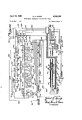
- Figure 1 is a general top plan view of a jig boring machine equipped with the programing apparatus of this invention.
- Figures 2 to 4 inclusive are diagrammatic views illustrating the motions of the table in relation to the measuring rods during a programing cycle.
- Figure 5 is an enlarged top plan view taken from Figure 1, showing the dial housing and selector mechanism with the cover removed.
- Figure 6 is a sectional view taken along line 6-6 of Figure 5, detailing the construction of the selector dials of the measuring apparatus.
- Figure '7 is a sectional view taken along line 7-7 of Figure 6, illustrating the driving connection from one of the dial-setting gears to a selector dial.
- Figure 8 is a sectional view taken along line 8-8 of Figure 6, showing the detent mechanism of one of the dials.
- Figure 9 is a sectional view taken along line 9-9 of Figure 6, showing the gear train from the ten-inch dial to the mechanism which shifts the ten-inch rods.
- Figure 10 is a fragmentary view showing the dial setting cams and actuating mechanism which shifts the teninch measuring rods to active or inactive position.
- Figure 11 is a sectional view taken along line 11-11 of Figure 10, further illustrating the selector cams for the ten-inch rod mechanism, the cams being shown in a zero or inactive position.
- Figure 12 is a sectional view similar to Figure 11, showing the cams rotated to a position in which the selected ten-inch rods are shifted to an active position.
- Figure 13 is a sectional view taken along line 13-13 of Figure 10, illustrating the stop mechanism which locates the ten-inch rods in their active or inactive position, the rods being shown in their inactive or lowered position in full lines and in the active position in broken lines.
- Figure 14 is a sectional view taken along line 14-14 of Figure 6, showing the dial setting gear train from the turret selector dial to the shaft which rotates the turret measuring rods to selected positions.
- Figure 15 is a fragmentary side elevation of the turret.
- Figure 16 is a sectional view taken along line 16-16 of Figure 15, further illustrating the turret.
- Figure 17 is a sectional viewtaken along line 17-17 of Figure 15, illustrating the abutment end of the turret.
- Figure 18 is an enlarged sectional view taken along line 18-18 of Figure 15, detailing the turret and its clamping mechanism in relation to the ten-inch rods.
- Figure 19 is a sectional view taken along line 19-19 of Figure 5, detailing the dial-setting gears and switchcs of the selector mechanism.
- Figure20 is a sectional view taken along line 20-20 of Figure 19, showing the pinions, clutches and actuating linkage of the dial selector mechanism.
- Figure 21 is an enlarged sectional view taken along line 21-21 of Figure 20, detailing one of the clutches which control the operation of the dial-setting gears.
- Figure 22 is a cross sectional view taken along line 22-22 of Figure 21, further detailing the clutch.
- Figure 23 is a sectional view taken along line 23-23 of Figure 19, illustrating the detent disk and directional switch which controls the'reverse rotation of the ten-inch dial at the start of a selecting cycle.
- Figure 24 is'a sectional view taken along line 24-2 of Figure 19, further detailing one of the selector switches d c utch i age.
- FigureQS- is a fragmentany view projected from Figure 24, further: illustrating the clutch linkage.
- Figure -26 is:a diagram showingthe electrical control system of the programing apparatus.
- the.programing apparatus of the invention is, shown in relation to a jig boring machine having a dial-operatedmcasuring apparatus of the aforesaid copending application, Serial No. 485,851.
- the dials of the measuring apparatus areset by hand to agiven lineal dimension;
- a power driven; positioning ,apparatusshifts the table or, crossslide from .a given position to a new position according ,to the :dimensionspecified by the measuring is mounted upon the column abovethe bed and includes avertical spindle, indicated diagrammatically at 11 in Figure '1, projecting downwardly toward the bed.
- the top surfaceofthe bed includes transverse ways 12 slidablysupporting a saddle or cross slide 13 for transverse motion across the bed; the upper surface of .the cross slide includes longitudinal ways 14 upon which is slidably'rnounted a work table 15.
- the workpiece 16 is clamped upon the table and is shifted withrespect to the spindle by the combined transverse and longitudinal motions of the saddle and table.
- the table may be shifted longitudinally along the ways 14 of the .saddle by operation of a hand wheel 17 which is connected through a gear train to a longitudinal lead screw 18.
- the saddleand table as a unit may be shifted transversely along thebed. by operating a second hand Wheel 20 which is connectedthrough a similar gear train to a transverse lead screw 21.
- the positioning apparatus shifts the slide and table by operation of the transverseand longitudinal splined shafts 22 and 23 of the saddle and table 'respectively,'as explained later, with referenceto the positioning mechanrsm.
- the final position of the table relative to the saddle is governedby the measuring apparatus in accordance with the setting of the dials of the dial housingwhich is indicated generally, at 24 in Figures 1 and .6.
- the dials are rotated to the required dimension by the selector mechanism of this invention indicated generally at 25, which -.is mounted directly on the dial housing 24.
- a similar dial housing 26 including an automatic selector 27 governs .the position of the saddle with respect to the bed.
- the measuring devices ofthe table and slide are is arranged in a series of ten rods and the shortest rod of each of the four sets represents zero, as indicated at 0 in Figure 2.
- the one-inch rods 31 are also arranged in-a series of ten, the shortest rod representing zero, the remaining rods increasing in steps of one inch, such that the longest rod provides a nine-inch measurement.
- the selected one-inch rods and decimal rods are shifted into axial alignment, they provide in combination any selected length measurement from 0.0000" to 9.9999,
- thefour ten-inch rods 30 provide teninch increments which are added to the decimal rods and one-inch rods, such that the combined rods provide any selected'measurements from 0.0000" to 49.9999 in steps of one ten-thousandth of an inch.
- the decimal rods 28 of the table are carried in respective dials which are mounted within the dial housing 24 as explained in detail later.
- the one-inch rods 31 are mounted within a turret 32 ( Figure 15) which is carried by the table 15, such that the one-inch rods move with the table relativeto the decimal rods of the dial housing ( Figure 3).
- the ten-inch measuring rods 30 are mounted relative to the saddle 13, and in order to conserve space, they shift transversely from an inactive position to a measuring position in alignment between thelselected decimal rods and one-inch rods ( Figures 3 and 18). When in the inactive position, the ten-inch rods reside in alignment with one another but below the line of movement of the one-inch turret 32 to allow the turret to pass with by the table.
- the measuring apparatus of the co-pending application comprises three groups of measuring rods or gauges of incremental length, the groups being indicated diagrammatically at 28, 30 and 31 in Figures 2 to 4.
- the rods indicated at 31 are arranged in length increments of one inch each and are identified in the specification as one-inch rods.
- the rods indicated at 30 are arrangedin increments of ten inches and are designatedas. ten-inch rods.
- the four sets of rods, indicated collectively at 28, are arranged in decimal increments and are designatedas decimal rods.
- the rods of each group act as length gauges and their dimensions are held within the exceptionally close limits of standard gauge practice.
- the decimal dials and one-inch turret are mounted for rotation upon a common axis, such that the ten rods of the turret and dials are-disposed in concentric circles to be rotated selectively into alignment with one another.
- the arrangement is such that the table may be shifted toward the. right to bring the turret rods into endwise contact with the decimal rods of the dials when the ten-inchrods are in their inactive position ( Figure 2).
- the table is shifted to the right to locate the workpiece at a base reference position relative to the spindle;
- the measuring apparatus locates the hole centers in spaced relation to the base reference surface or point previously established;
- the measuring rods are shifted to a zero position In zero position, and in the subsequent measuring positions, the selected decimal and'one-inch rods reside in axial alignment with one another between a spring loaded feeler rod 33 and a thrust rod 34, the aligned rods being shifted -to-- ward the right by an abutment rod 35 which iscarried
- the abutment rod 35 contactsthe selected one-inch rod, suchthat the motion of the table is transmitted from the abutment rod 35 through the selected one-inch and decimal rods and thrust rod 34, to the feeler rod 33.
- the feeler rod is arranged to stop the table at its selected position during the subsequent positioning operations as described later. In principle therefore, the measuring rods act as gauges or spacers between the table and saddle to
- the positioning apparatus is shown diagrammatically in relation to the table and includes a reversible rapid traverse motor 36 and a positioning motor 37.
- the traverse motor first shifts the table at a traverse rate to a back-up position to allow the measuring rods to be shifted to gauging position thereafter the traverse motor shifts the table toward the right at the traverse rate during the positioning cycle.
- the traverse motor 36 is deenergized and the positioning motor 37 is energized to inch the table slowly to its final position.
- the slow positioning rate makes it"possible to stop the table precisely at its final position without danger of over-travel.
- the positioning motor is reversed momentarily after it stops the table at final position in order to relieve the drive system of any stresses between the motor and table, thereby to prevent minute shifting after the table is stopped.
- the traverse motor 36 is in driving connection with the lead screw 18 which, as indicated earlier, may also be rotated by the hand wheel 17.
- the lead screw 18 is threaded through a nut 38, the nut being confined endwisely within a gear box 40 attached to the table as indicated in broken lines. Rotation of the traverse motor 36 in one direction thus rotates the lead screw to shift the table toward the left to its back-up position and reversal of the motor traverses the table toward the right.
- the traverse motor speeds up the positioning cycle since it shifts the table at a speed which is considerably greater than the positioning speed.
- the positioning motor 37 is in driving connection with the splined shaft 23 previously noted, the splined shaft being sildably keyed to a worm 41 meshing with the teeth of a worm wheel 42.
- Worm wheel 42 drives a second worm 43 which meshes with the worm wheel 44 of nut 38, thus providing a reduction drive for rotating the nut 38 at a slower positioning rate relative to the lead screw 13.
- feeler rod '33 projects from a switch box 45 which is interconnected with the control circuit of the positioning apparatus. Since the control unit and its associated circuit does not form an essential part of this invention, this portion of the posi-. tioning apparatus has been omitted from the drawings, the complete apparatus being disclosed in the aforesaid Knosp patent.
- the switch box 45 comprises a housing which is attached directly to the dial housing ( Figure 6), the outer end of the feeler rod 33 residing within the dial housing in alignment with the last decimal rod of the series.
- the feeler rod is spring biased toward the decimal rod and its movement toward the rod is limited by a stop element (not shown) such that the end of the rod does not interfere with normal rotation of the deci-. mal rod dial.
- the control housing encloses a rapid traverse switch and a final positioning switch (not shown) both of which are in operative connection with the feeler rod.
- the table In initially setting up the machine for boring a series of holes, the table is first shifted to a position to align the reference surface of the work precisely with the axis of the spindle as explained earlier.
- the reference surface or point is located at the left end of the work, and the hole centers are measured from the reference point toward the right.
- the edge46 of the workpiece may represent the reference plane, the table being shifted toward the right, as indicated, to locate the sec.- ond hole 47 (broken lines) in' alignment with spindle 11.
- the first hole 48, previously bored also was measured from edge 46.
- the table In establishing the reference point, the table preferably is shifted to its zero position to the right as noted previously with respect to Figure 2.
- the turret is adjustable lengthwise relative to the table to bring the zero one-inch and decimal rods into endwise abutment between the abutment rod 35 and feeler rod 33 as indicated.
- the adjustment issuch that the spring loaded feeler rod is depressed slightly to a position in which it normally deenergizes the positioning motor at the final position of the table at the selected hole center.
- the table After setting for the base reference point, the table is shifted toward the left as shown in full lines in Figure 3 to allow the selected measuring rods to be shifted to their measuring positions. This allows the spring loaded feeler rod to spring to the left to its normal position.
- the positioning cycle is initiated.
- the rapid traverse motor 36 is energized to shift the table toward the right at the traverse rate by rotation of lead screw 18.
- the table shifts abutment rod 35 and turret 32 toward the right, thus taking up the clearance 50 and 51 ( Figure 3) which exist between the aligned measuring rods.
- the control circuit plugs the rapid traverse motor 36 to a stop and energizes the positioning motor 37.
- the positioning motor now continues feeding the table toward the right at a slow positioning rate until the feeler rod trips the positioning switch at final position.
- the positioning switch trips when the feeler rod reaches the same preloaded pressure for which it was set initially at the reference position ( Figure 2), hence the new position of the table and workpiece is determined precisely by the additive length of the selected measuring rods under the same preloaded pressure. It has been found in practice that the hole centers are located consistently within a tolerance of plus or minus .0001" upon each operation.
- the table is traversed at the rate of 72 inches per minute toward the right until it displaces the measuring rods and feeler rods sufiiciently to trip the rapid traverse switch. At this point, the positioning motor continues the advancement at the rate of .415 inch per minute until the table is inched to its final position.
- control circuit of the positioning apparatus As shown diagrammatically in Figure 26, the electrical energy is supplied to the control circuit of the positioning apparatus by power lines 52, the traverse and positioning motors being energized by the power lines 53 and 54 which lead from the control circuit.
- the control circuit forms no part of the invention and for this purpose, has been shown in block form in Figure 26. It will be understood that the control circuit includes the necessary relays and other components for providing the sequential operation of the traverse and positioning motors in response to the feeler rod 33.
- the positioning cycles are governed by push button switches as indicated diagrammatically in Figure 26.
- the push button indicated at 55 shifts the table toward the left and the push button 56 shifts the table toward the right.
- the intermediate push button 57 initiates the positioning cycle after the table has been shifted to the left and the measuring rods selected.
- a stop button 58 decommissions the entire apparatus upon being depressed.
- the saddle posi- 'tioning apparatus is provided with a similar set of manual switches.
- the programing apparatus governs the movements of the table "and the selection of measuring rods in proper sequence.
- the manual switches 55 and 56 are utilized only in the initial set-up operation, as described earlier.
- the table traverse mo- .tion toward the left is under control of the programing one-inch rods to be shifted to their gauging position.
- a back-off switch 64 which is actuated by a tripping element 65 mounted on thrust rod 34. This switch represents the zero position of the table and it is tripped when the pressure is applied to the thrust .rod at the zero set-up position ( Figure 2.).
- the back-E switch 64 is interconnected in the control circuit to initiate the dial selecting cycle of the programing apparatus after the t able'has been shifted to a back-off position.
- This switch is tripped by the table when the table has been shifted to a back-off position which is slightly greater thannine inches from the zero position to allow the one-inch turret to be rotated to bring the rods from one to nine selector .housing includes selector gears which are in .driving'connection with the gears of the selector dials.
- the dial housing encloses six selector dials or matrix members which are rotatably 'journalled upon'the axis of a dial'shaft 72.
- the first four .dials which are indicated at 73 to 76, carry the decimal measuring rods 28.
- the one-inch dial, indicated at 77, is in driving connection with the turret 32 and rotates the selected one-inch rod of the turret to its measuring position.
- the ten-inch dial which is indicated at 78,
- each dial is in driving connection with the ten-inch rods and serves to shift the selected ten-inch rods into measuring position.
- Each dial is provided with a graduated. ring 30 which indicates the order of length increments, such that the dials collectively provide direct reading of the selected dimensions through the'transparent window 68.
- the decimal and one-inch dials have ten graduations indicating 0'to 9 and theten-inch dial has five graduations indicating 0 to 4.
- the dials are rotated'to'the dimension 37.9625", the selected measuring rods for this dimension being shown diagrammatiinches into measuring position. In other words, this- Y switch regulates the back-up position when no ten-inch rods are to be shifted.
- the programing apparatus includes a cycle control switch which is depressed by an operator to start the-cycle.
- the button When the button is depressed, the table is shifted toward the left ( Figure 3), the back-off position being controlled by the programing apparatus which sends a signal'to the back-off switches.
- a signal is sent to back-off switch 62 to cause the table to be backed off-until this switch is tripped, thus allowing the three ten-inch rods and the required one-inch and decimal rods to be shifted to measuring position as shown.
- the programing cycle is described later in detail with reference to Figure 26.
- Dial mechanism vention the following description has been limited to the essential features by which the dial housing coacts with the programing apparatus in selecting the measuring rods.
- the dial housing comprises,
- each decimal dial is in the form of a barrel having a central bore 81 rotatably .journalled upon the dial shaft 72 by means of ball bearings 82. "The ball bearings are located by suitable spacers .83 slipped upon the dial shaft 72 between the bearings. 'Each decimal dial includes a series of measuring rod bores spaced equally from one another in a circle which is concentric to the dial shaft such that the decimal rods 23within the bores may be indexed in alignment with one another as indicated in Figure 6. As explained earlier, the four sets of decimal rods 28 provide the measurements in tenths, hundredths, thousandths, and ten-thousandths of an inch from the zero setting. In the present disclosure, the shortest rod of each of the decimal sets has a'length of 1.000, the rods of each set increasing in the respective orders indicated above from this basic length.
- the selected decimal rods 28 reside in alignment'between the end of the thrust rod 34 and feeler rod 33, the spacing between the ends of the two rods being slightly greater than the additive length of, the longest decimal rods of the series.
- theends of each red are tapered as 'at 85, allowing the rods to shift endwisely without interference'during relative rotation of the dials.
- the dials In order to hold the dials in selected positions, the dials (excepting the ten-inch dial) includes a detent wheel 86 which is notched as at 87, the notches corresponding with the location of the dial graduations ( Figure 8). Each detent wheel is engaged by a roller 88 carried on a spring loaded detent 'arm 90. When the roller is engaged in one of the notches of the detent wheel, the selected measuring rod is located in axial alignment with the rods 33 and 34 as indicated in Figure 9.
- the turret 32 and the ten-inch rods 30 are located within an elongated housing 91 which extends from the dial housing 24 as shown in Figures 1 and 18.
- the teninch dial 78 shifts the four ten-inch rods successively from zero position to the measuring position as the dial is advanced from its zero graduation.
- the turret and decimal dials are rotatable upon a common axis, the rods of the turret and dials being spaced in concentric circles for selective alignment. It will be observed in Figure 18, that the ten-inch rods 30 reside below the plane of movement of the turret when in their inactive position. When shifted to measuring position, the selected ten-inch rods reside along the same axis as the selected decimal and one-inch rods as shown in broken lines in Figure 18.
- the ten-inch rods 30 are se'-" lected by respective cams indicated generally at 92 which are in driving connection with four rock shafts or tubes 118 to 122, telescopically interfitted for rotary motion relative to one another.
- the tubes are rotatably journalled within the elongated housing. 91 as explained later, each rock shaft having a respective pair of rocker arms 97 secured thereto, the outer ends of which include bores slidably embracing the endwise portions of the respective ten-inch rods.
- Each ten-inch measuring rod is yieldably biased toward the left by a compression spring which urges the rods endwisely against a stop (not shown).
- each of the rock shafts include a stop collar 98 (Figure 13) fixed to the shaft and provided with a pair of shoulders 100-100 which are engaged by stop screws 101-101 threaded through the bottom wall 102 of the elongated housing.
- the left hand stop screw engages its shoulder with the measuring rod disposed in alignment with the selected one-inch rod of the turret as shown in broken lines in Figures 13 and 18.
- cam levers 103 ( Figures l--12), one for each tube, the levers being nonrotatably clamped to the-respective tubes.
- Each lever includes a cam roller 104 tracking upon a respective cam.- The cams are so arranged that the ten-inch rods sequentially are elevated to the active position of Figure 13, starting with the first measuring rod to the right.
- the ten-inch dial 78 is rotatably journalled upon a boss 105 projecting from the intermediate wall 106 of the dial housing Boss 105 has an internal bore 107 concentric with the dial shaft 72, the thrust rocl 34 projecting into the bore for cooperation with the decimal measuring rods.
- the cams 92 are in driving connection with the ten-inch dial 78 by way of a gear train ( Figure 9), consisting of a gear 108 secured to dial78 and rotatably journalled on boss105.'
- a gear 110 meshes with dial gear 108 and is loosely journalled on a counter shaft 111 which is rotatably journalled in the dial housing.
- Gear-110 includes a pinion 112 meshing with a reversing idler gear 113 journalled on a stub shaft 114 of the housing ( Figures 6 and 9).
- the idler gear 113 meshes with a gear 115 non-rotatably secured to the cam shaft 116.
- the four earns 92 are nonrotatably 'secured to shaft 116, the cams having leading edges 117 located in four angular positions, such that the four leading edges are advanced successiveively to the cam rollers as shaft 116 is rotated in the rod selecting direction indicated by the arrows in Figures 9 and 12.
- the tracking surface of the cams is concentric to shaft 116, the tracking surfaces having respective lengths as indicated by angles A to D ( Figure 11) and have common trailing edges.
- the four cam levers 103 which correspond to the cams, are indicated at A to D and they are actuated in sequence by the leading cam edges 117.
- the angles A to D correspond to the degree of rotation imparted to the cams upon each stepwise advancement of the ten-inch dial from one graduation to the next.
- dial 78 is advanced from zero to the first graduation in the direction indicated by the arrows in Figure 9
- the leading edge 117 of the first cam engages the roller 104 of lever D which is secured upon the tube 113.
- the leading edge of the next cam engages the roller of lever C in a similar manner to rotate tube 120 and elevate the second measuring rod. Stepwise rotation of the cam through the remaining angles is effective to rock in sequence the tube 121 and 122 to elevate the remaining rods of the series.
- each rock shaft includes a collar 125 secured to the tube adjacent the left bearing block 123.
- a torsion spring 126 has one end anchored to the collar 125 as at 127 and has its opposite end anchored in the bearing block 123.
- Each spring 126 is slightly preloaded to urge the tube in the rod lowering direction, such that the cam rollers 104 are urged by the springs against the tracking surfaces of the cams.
- the one-inch turret 32 is rotatably supported by the slide block 128 which is clamped to the table for movement therewith; the slide block may be unclamped and shifted with respect to the table when the machine initially is set up as previously noted with respect to Figure 2.
- the turret is rotated by the hexagonal selector shaft 130 which is in driving connection with the one-inch dial 77 through a gear train as described below.
- the hexagonal shaft extends from the'dial housing 24 and through the elongated housing 91 on an axis common to the axis of dial shaft 72.
- the turret is slidably keyed to the hexagonal shaft for rotation With the shaft in response to rotation of the one-inch dial 77.”
- the end portion of the hexagonal shaft includes a pilot shaft 131 rotatably journalled in the intermediate wall 106 of the dial housing.
- the one-inch dial 77 is keyed to the hub of the dial gear 132,.the gear being rotatably journalled uponthe boss 105.
- Gear 132 is in mesh with a gear 133 which is secured to the counter shaft111 and drives a pinion'134 fixed to the outer end of the countershaft.
- pinion 134 meshes with an idler. gear 135 rotatably journalled on :stub shaft 136, the idler gear meshing .the final drive gear 137 which is secured to the pilot shaft 131.
- the gear train from the dial rotates the hexagonal shaft at a. one- .to-one ratio in the direction indicated by the arrow in 1 Figure 16.
- the slide block 128, which carries the turret is clamped in its adjusted position along .the edge of the-table by a T-nut 140 slidably engaged in a T slot 138 of table 15 and threaded on a stud 141-.
- the slide block includes .a tapered socket 142 and a clamp screw 143 includes a tapered end 144 which cams into the socket to draw the T rm into clamping engagement.
- the clamping nut is rotated hyvmeans of the clamp handle 145 attached to clamp screw 143.
- the slide block is in permanent connection with the T-slot by a pair of similar T-nuts slid- :ably confined in the slot and connected to the .slide block by studs (not shown).
- the turret '32 is rotatably confined endwisely between the arms 146146 of the slide block 128 as shown in Figure 15.
- the turret is of sectional construction and includes a sleeve 147 journalled in the arms 146 and .;slidably keyed to the hexagonal shaft-130 as at 148.
- decimal rods for selective alignment therewith.
- the left end of'the sleeve 147 which rotates the turret includes a head 154 having ten detent recesses 155 which correspond to the spacing of the measuring :rods.
- the :detent recesses .are'engaged by a ball 156 carried in :the arm 146 of the slide block and urged toward the recesses by a compression spring.
- the detent recesses latch the turret :in its selected rotary measuring positions.
- the 'abutment rod 35 also is mounted in the arm 146 and provides a gauge surface which contacts the end ofthe selected measuring rod.
- the turret mounting arrangement allows the turret to be shifted relative to the table to a zero positionwhen the machine initially 'is set up, with the base reference point of the work aligned with the axis of the spindle.
- the clamp lever 145 may be actuated to clamp the slide block and turret in fixed position to the table.
- the apparatus is then in condition to be placed under the control of the programing apparatus for setting the measuring rods and positioning the table.
- Dial selector mechanism Referring to Figures and 6, the six dial setting'gears 157 to 163, which rotate the dials, are mounted on 'a drivenshaft 164 journalled as at 165 in the end walls 166 and intermediate wall 167 of the selector housing. These walls form continuations of the walls of the dial housing 24 to which they are bolted as at 71 as previously noted.
- the four decimal dials areprovided with dial gears 168 to 172, which mesh with the setting gears 157 to 161.
- the setting gears 162 and '163 mesh with the gears 132 and'lllitl of theten-inch dial 78 and one-inch dial 77.
- the dial gears 132 and 108 form a part of the gear trains of the ten-inchrods and turret as described earlier.
- the .setting gears .157 to 163 are drivenby respective pinions174 which are loosely journalled onja drive shaft 175 rotatably journalled as at 176 in the walls of housing 25.
- the individual pinions 174 are coupled selectively to the driveshaft by individual clutches 177 which are .normally spring-urged to coupling position.
- the pinions are uncoupled from the drive shaft by respective sole noidsindicated at 178 to 185 which are linked to the 'clutches as described later.
- the clutches normallyare spring biasedto coupling position ( Figure 24) and are shifted to uncoupled. position when'the solenoids'individually are energized. This occurs when the dials have been rotated to their selected positions, thedial driving gears being provided each with a brush which completes the circuit when .the preselecteddial position is reached.
- the drive shaft 175 is driven .by aconstant speed dial motor 186 having a worm 187 .meshing with a worm 'wheel 188 attached to a stub shaft 190.
- the stub shaft is journalled as at 191 in a 1 upon drive shaft 175.
- Each clutch spool includes a pair of driving pins 201201 projecting from the face of the spool and passing slidably through bores in the pinion 174 which it drives.
- -A drive collar 202 which is attached to the drive shaft as'at 203, provides a stop which locates the pinion along the shaft in alignment with the setting gear with which it meshes.
- each pinion is contacted by a spacer sleeve 205 slipped upon shaft 175.
- the clutchspools areslidably mounted on thespacer sleeves.
- the face of the collar, which contacts the side of the pinion, is provided with a slot 2% extending across its diameter, the. slot having 'a width to .receive the ends of the driving pins 201.
- the clutch :spool is shifted toward .the pinion to its engaged position ( Figure .21)
- the ends of the pins project into the slot ofthe driving collar. Since the driving collar is attached to the drive shaft, it provides a driving connection through. the pins to the pinion 174.
- the spool is shown in its disengaged position in'broken lines in Figure 25, as explained below.
- each solenoid includes a 'vertical plunger 208 which is slotted as at 21%).
- Each plunger is normally'urged upwardly by a compression spring211 having its lower end seated upon the top surface of the solenoid.
- a yoke-actuating lever 212 has an end .fitted into the slot of the plunger and connected to'it'by a pivot pin 213 ( Figure 25).
- the opposite end The yoke is pivotally supported by opposed shoulder screws215 threaded through the flanges 216-216, of wall'207, the-screws having endwise portions pivotally passing through the limbs of the yoke. .It will be noted in Figure 25, that the screws 215 are located upon a common axis below the axis of the yoke pins 198, such that the yoke pins swing in an arc 'to shift theclutch spool along the drive shaft.
- the dial driving mechanism includes a reversing gear 217 which is pinned as at 218 to shaft 164 ( Figure 19). The purpose of this gear is to rotate the setting gear 108 and ten-inch dial 78 back to a zero position at the start of the selecting cycle, thereby to ,lower the teninch measuring rods.
- the reversing gear 217 is driven by a pinion 220 rotatably mounted on drive shaft 175 and controlled by a reversing clutch 221.
- the reversing clutch is identical to the structure described above exceptthat the relationship of the parts is reversed.
- the reversing clutch is actuated by a reversing yoke 222 which shifts the clutch collar toward the left (as viewed in Figure 20) to an engaged position and toward the right to a disengaged position.
- the reversing yoke is actuated by a reversing solenoid previously indicated at 178 having a spring loaded plunger as described earlier.
- the plunger of the reversing solenoid is pivotally connected to a lever 223 having its outer end pivotally connected to a screw 224 attached to flange 216.
- the yoke is pivotally mounted, by shoulder screws 215 as described above, and a yoke lever 225 is attached to the yoke at the axis of the shoulder screws.
- the yoke lever has an end portion 226 bent to reside parallel with lever 223.
- a pin 227 projecting from lever223 pivotally connects the two levers.
- the reversing solenoid is energized, its plunger swings lever 223 downwardly and this motion swings theyoke lever and yoke in a direction to shift the reversing clutch spool toward the right (away from pinion 220) to uncouple the reversing pinion 220 from drive shaft 175.
- the ten-inch dial is rotatable only to the extent permitted by its cams 92; consequently, it is rotated back to zero at the start of a measurement selection cycle.
- the reversing pinion 220 meshes with are erse idler gear 228 which is loosely journalled on a stub shaft 230 mounted in the end wall 166 of the housing ( Figure 9).
- the reverse idler in'turn meshes with the gear 217 which is pinned to the shaft 164, noted earlier.
- the six setting gears 157 to 163 establish electrical circuits which energize their solenoids and cause the clutches to be disengaged after the gears have rotated their preselected positions as explained in detail later.
- the setting gears 157 to 163 are formed of a dielectric material, such as fiber composition.
- Mounted adjacent each gear is a stationary electrical contact ring 231, also formed of dielectric material and having contact buttons 232 corresponding in number to the digits on the dials ( Figure 24).
- the contact rings'of the live setting gears 157 to 162 which drive theone-inch dial and four decimal dials, each carry ten contact but I16 tons corresponding to the digits zero to nine.
- the contact ring for the gear 163,'which drives the ten-inch dial, is provided .with. five contact buttons corresponding to the digits zero to four. v a w v
- the individual buttons of each contact ring are energized by the reading device of the programing apparatus in accordance with the selected position to which the dial is to be rotated, one button of each ring being energized during the selecting cycle, as described later.
- Each setting gear is provided with slip ring 233 formed of metal and each gear is provided with a brush or wiper 234 in wiping contact with the slip ring and having a portion traversing the contact buttons during rotation of the setting gears, as explained later in detail with reference to the control circuit.
- the arrangement is such that the gear rotates during the selecting cycle until the wiper reaches that contact which is energized, at which point an electrical circuit is completed to the solenoid which is associated with that gear.
- the solenoid Upon being energized, the solenoid disengages the clutch, causing that particular gear and its dial to come to rest at the preselected position. This establishes the setting of that dial, and in a similar manner, the setting of all of the other dials individually.
- each setting gear is counter-turned as at 235 to receive the slip ring 233, which may be pressed or otherwise attached to the gear.
- a washer 236 is slipped upon the counter-turned hub and confines the contact ring in position, the washer being locked on by a snap ring 237.
- the contact buttons 232 are in the form of rivets passing through the contact ring 231 and engaging a terminal 238 to which the electrical lead wires 240 are attached.
- the brushor wiper 234 is formed of flexible sheet metal and is generally U-shaped as viewed in Figure 24 providing one limb 241 which serially engages the contact buttons and a second limb 242 which is in wiping engagement with the slip ring 233.
- the wiper 234 is attached to the gear by a pair of rivets 243.
- An electrical lead wire244 is connected as at 245 to the slip ring, such that a circuit is established by way of the wiper between the slip ring and the selected contact button.
- the construction of the contact rings is identical for all the setting gears except that the ring which controls the ten-inch dial is provided with five contact buttons, as noted above.
- each ring is mounted for rotary movement with respect to the counter-turned gear hub 235 upon which it is journalled.
- a pair of threaded rods 246- 246 extend lengthwise between the intermediate wall 167 and end wall 166 of theselector housing, the rods passing through respective arcuate slots 247247 formed in the extended portions 248 of the contact rings.
- Each rod is provided with pairs of nuts 250 which exert a clamping action against opposite sides of the dial ring portion 248.
- Driven shaft 164 is provided with a detent disk 251 (Figure 23), secured by a set screw 252 and including a detent notch 253.
- a directional control switch 254 is mounted in stationary position upon intermediate wall 167 and its plunger is actuated by a yieldable arm 255 attached to the switch, the outer end of the arm having a roller 256 tracked against the disk.
- the reversing clutch and gear train cause rotation of detent disk 251 in the direction indicated by the broken line in Figure 23. If the ten-inch dial 78 is set at some graduation other than zero at this point, the reverse rotation drives the dial .to its zero position (as in Figure 23) thereby to lower the ten-inch rods.
- the directional control switch As the notch 253 passes beneath the roller, the directional control switch is tripped momentarily, causing the reversing clutch to be disengaged, as explained later with respect to the electrical circuit. It will be understood at this point, that the relationship of the notch 253 and roller 256 represents the zero position of "the dial.
- the programing circuit for regulating the table motions is electrically interconnected with the selector mechanism 25 of dial housing 24 and is also interconnected with the switch box 45 of the table positioning apparatus.
- the present description is directed to the circuit for controlling the table; however, it will be understood that the circuit for controlling the saddle is identical, and for this reason, has been omitted.
- the position of the workpiece depends upon the longitudinal position of the table and upon the transverse position of the saddle; accordingly, both the table and saddle programing circuits are energized during the positioning cycle.
- the table dimension and saddle dimension preferably are signalled from the same program reader.
- the box labelled program reader represents a commercial reading apparatus which produces electrical signals from punched cards, perforated tape or other coded record media corresponding to the dimensions to be selected.
- the reader also may be electrically interconnected with the saddle control circuit, such that the saddle position as well as the table position, may be signalled from the same record.
- the dimension 37.9625 used previously in describing the selection of measuring rods, is used to illustrate the operation of the programing apparatus.
- the box which is labelled program control circuit represents the system of relays and other components which regulates the sequential operation of the selector dials, table back-off motion and table positioning motion.
- the teninch dial 78 is in driving connection with the cams 92 and the degree of its rotary motion is limited by the cams.
- the dial is rotated to its 4 graduation and can be rotated no further.
- the dial is rotated in the reverse direction back toward zero, then the fourth measuring rod is lowered first, then in sequence, the third, second and first rods are lowered.
- the programing apparatus is arranged to rotate the ten-inch dial in reverse back to zero at'the start of the dial setting cycle to lower the rods to inactive position, then at a later point, the first and suc cessive rods are elevated in sequence by rotating'the dial from zero in the forward direction, that is, in the ascending order.
- the program cycle is initiated manually by depressing the cycle switch 260, shown as part of the program circuit box.
- a a circuit is completed through the program circuit to the positioning apparatus, causing the table to traverse tQ'. Ward the left to a predetermined back-01f position,
- the program circuit is energized by the feed lines: 261 and 262, which may represent a low voltage control circuit.
- the control lines and feed lines are designated as positive or negative to identify the complete circuits.
- the reader and program control boxes. complete the circuits fromone feed line, through the reader, and through the various switches back to t esecona feed line, the polarity of the various control lines indicating the feed lines with which they connect, rather than' their electrical polarity.
- Thefr'eader is electrically connected to the ten contact buttons 232 (0 -9)v ofeach of the five' contact rings of the digit selector switches or'emitters 231.
- the five contacts 232 (0-4) of: the ten-inch contact ring or selector switch are connected to the reader contacts by way of the lines 263 and are energized according to the ten-inch rod (of rods) to be shifted to measuring position.
- the brush 234 of this switch also is rotated by its gear 163 from the zero position in the ascending order until it finds the contact which is energized by the reader, at which point the clutch 177 for this switch is disengaged to stop the ten-inch dial in its selected position.
- the contacts of the ten-inch selector switch are connected to the stationing switches 6Gto 63 and 66 by way of the five branch lines 264 d
- the diagram shows the back-off switch and the station ing switches from zeroto three tripped fr om their nor.- mal position to the position they assume when the table is shifted toward the left as in' FigurefB.
- The" normal position of these switches is indicated in brokenlines in the diagram.
- the opposite side of the position circuit is completed from feed line 261 by way of line 267.
- the position box now energizes the traverse motor 36 by way of power lines 53 in a direction to shift the table toward the left.
- the table continues its left hand motion until it trips the third stationing switch 62 to the position shown in full lines.
- the program box After the forward clutch solenoids 180 to 185 are energized, the program box provides a time delay, then energizes the dial motor 186 by way of line 272, this line oeing placed in circuit with the feed line 261. The circuit of the dial motor is completed by the line 273 which is connected to feed line 262, thus completing the motor circuit.
- the brush 234 of the ten-inch selector switch is shown in its zero position in full lines in the diagram.
- the gear and brush will first be rotated in reverse as indicated by the arrow in dot-dash switch and causing the switch to send a signal from the energized line 268 through line 270 to the program box.
- the signal causes the program box to energize the reversing clutch solenoid 178 by way of line 274.
- the opposite side of the solenoid circuit is completed by way of line 273 connected to the feed line 2 62.
- the reversing clutch is now disengaged by its solenoid while the dial 'motor continues running.
- the brushes 234 of the selector switches are connected to the program box by the respective lines 244 indicated earlier in Figure 26.
- the circuit is completed from the reader lines 240, through the brushes and contacts to the respective lines 244.
- the program box energizes the solenoid for that particular selector switch, thus disengaging the clutches and stopping the brushes and dials in the preselected positions indicated by the broken line arrows. 1
- the control box deenergizes line 275 which leads to the forward clutch solenoid of the ten-inch selector switch, thus engaging the forward ten-inch clutch.
- Gear 163 and its brush are now rotated from zero in the forward direction, as indicated by the arrow in dotted lines, until the brush contacts the 3" contact.
- the circuit is completed from the program reader (lines 263) through the brush to line 276 leading to the program box.
- the program box Upon being energized by line 276, the program box energizes the line 275 which leads to the forward ten-inch clutch solenoid 180, causing the clutch to be disengaged. All of the selector switches and associated dials are now in the signalled position with the measuring rods in the gauging positions as shown in Figure 3.
- a Line 276 also causes the program box to deenergize the dial motor 186 after a short delay following disengagement of the ten-inch clutch.
- the apparatus is now ready to initiate the positioning cycle.
- a line 277 extends from the program box to the positioning box. This line is energized by the program box when the dial motor 186 is deenergized, the circuit being completed by line 267 to start the cycle.
- the program box also deenergizes all of the clutch solenoids at this point.
- the positioning cycle is initiated when the operator depresses a starting switch indicated at 57 in Figures 1 and 26.
- the control circuit of the positioning apparatus first energizes the traverse motor in a direction to shift the table toward the right at a traverse rate, then to deenergize the traverse motor and energize the positioning motor to inch the table to its final position under the control of fceler rod 33.
- the positioning apparatus operates in the same manner under control of the programing circuit, that is, the line 277 signals the positioning circuit, the cycle thereafter being under control of the positioning apparatus.
- the programing apparatus for the saddle is identical to the table mechanism described above.
- the saddle is shifted outwardly at the start of the cycle, then the dials of the saddle dial housing 26 are selected by the selector mechanism 27 as previously noted.
- the point on the work is precisely located in alignment with the drill spindle.
- the programing circuits of the table and slide may be interconnected with the control system of the drill head motor to initiate the boring operation and also to select the feed rate and spindle speed in accordance with the drill diameter and other variable factors.
- This apparatus has been omitted since it is not essential to the invention.
- the operator again depresses the cycle switch 260 to position for the next hole. This location may be either to the right or left of the hole previously bored, depending upon the data which is fed into the program reader.
Landscapes
- Engineering & Computer Science (AREA)
- Physics & Mathematics (AREA)
- General Physics & Mathematics (AREA)
- Automation & Control Theory (AREA)
- Mechanical Engineering (AREA)
- Perforating, Stamping-Out Or Severing By Means Other Than Cutting (AREA)
- Drilling And Boring (AREA)
- A Measuring Device Byusing Mechanical Method (AREA)
Description
April 12, 1960 R. N. KNOSP PROGRAMING APPARATUS FOR MACHINE TOOLS 10 Sheets-Sheet 1 Filed May 1, 1957 INVENTOR. BY
W116 M in, ATTOENEYS.
April 12, 1960 R. N. KNOSP 2,932,088
PROGRAMING APPARATUS FOR MACHINE TOOLS Filed May 1, 1957 10 Sheets-Sheet 3 I 7,5 7, Z 4,1e2 K 1 0 f f 1 77132 76 m as 7 3 9 1 5 a 1 ,L-G7 45 4 0 7 3 6 1/ 33 l 54- 75?. M f L and l I) v I 5 7 3 -zs1 7 we, 1 -70 m 15 a C m l, INVENTOR.
mmlmzzz;
ATTdf/VEYEL April 12, 1960 R. N. KNOSP 2,932,083
PROGRAMING APPARATUS FOR MACHINE TOOLS Filed May 1, 1957 10 Sheets-Sheet 4 A! II I! I l LJ mxammw A T TOENE Y5.
April 12, 1960 R. N. KNOSP 2,932,083
PROGRAMING APPARATUS FOR MACHINE TOOLS Filed May 1, 1957 10 Sheets-Sheet 5 Y 72 v f-wa 111 INVENTOR.
April 12, 1960 R. N. KNOSP PROGRAMING APPARATUS FOR MACHINE TOOLS 10 Sheets-Sheet 6 Filed May 1, 1957 NVENTOR.
44 TTOf/VEXQ.
April 12, 1960 7R. N. KNOSP PROGRAMING APPARATUS FOR MACHINE TOOLS 10 Sheets-Sheet 7 Filed May 1, 1957 5r l/l//l\.-
INVENTOR.
4TTOEAIEY5.
April 12, 1960 R. N. KNOSP PROGRAMING APPARATUS FOR MACHINE TOOLS Filed May 1, 1957 10 Sheets-Sheet 8 1 207 INVENTOR.
aw Egg. 20
April 12, 1960 R. N. KNOSP PROGRAMING APPARATUS FOR MACHINE TOOLS Filed May 1, 1957 10 Sheets-Sheet 9 INVENTOR.
59.24 fi di Ma;
April 12, 1960 R. N. KNOSP PROGRAMING APPARATUS FOR MACHINE TOOLS 10 Sheets-Sheet 10 Filed May 1, 1957 IUZTNZO v iqu uoma "to-x23 $10285 5a.. n 05:... 1.559.
ARM
IN VEN TOR.
07'7'0EA/EY5.
r G APPARATUS F OR MACHINE TGOLS 25 Claims. (Cl. 33-9125) This invention relates to a programing apparatus which regulates the motions and positions of a shiftable machine tool element so as to provide a sequence of machining operations at preselected locations on a workpiece in response to coded record media which is fed into the programing apparatus.
A primary objective of the invention has been to provide for the rapid and precise positioning of the shiftable machine element, such as a table or slide, utilizing selective lineal measuring rods or gauges which are shifted in response to the programing apparatus into alignment with one another, such that the additive length of the measuring rods, establishes precisely the preselected locations of the shiftable element.
In order to clearly disclose the principles of themvention, the programing apparatus is disclosed in relation to a jig boring machine which is utilized in' the precise centering and machining of holes. The conventional jig boring machine is intended primarily for the boring of jigs and the like, the hole centers being located with an exceptionally high degree of precision. The jig boring machine ordinarily isnot used in production work since each hole is located by gauge rods which are placed in the machine by hand, often incombination with adjustable micrometer gauges. The setting up and adjustment of the machine in this manner requires the services of a skilled machinist and consumes a great deal of time.
In general, a conventional jig boring machine comprises a bed having a vertical column having a rotating tool spindle whichis shiftable along a vertical axis relative to the bed. A work table is slidably mounted upon jf tes Patent j a cross slide or saddle for longitudinal motion relative to the saddle, and the saddle is shiftable transversely with respect to the bed of the machine, The work, which is clamped to the table, is located relativeto the spindle by the coordinated transverse and longitudinal movements of the saddle and table. The conventional measuring rods, referred to above, are utilized for positioning the saddle transversely and for positioning the table lineal multiples of ten inches, a second group graduated in increments of one-inch, and a third group graduated in decimal increments. The decimal rods comprise four sets, each set having graduated lengths in the order of tenths, hundredths, thousandths, and ten-thousandths of an inch. A ten-inch dial is arranged to select the teninch rods, a one-inch dial provides selection of the one- 2 inchrods, and an individual dial shifts each set of decimal rods. There is thus provided a series of six dials, all of which arelocated in a dial housing on a common axis of rotation, the dials having digit graduations to provide direct reading of the selected dimension. The dials shift their respective measuring rods to active measuring position as the dials are rotated to bring their graduations to a reading position.
-In its application to a jig boring machine, one dial housing is mounted relative to the table for governing the table position and a second dial housing is mounted relative to the saddle for governing the saddle position. In locating a hole center, the two sets of dials are roa tated to the desired setting, thus providing the transverse and longitudinal coordinates for locating the hole center. This measuring apparatus provides the same order of precision as the conventional measuring rods which must be selected and adjusted by hand.
The dial-controlled measuring apparatus of the cm pending application is intended particularly to be used in combination with the automatic positioning apparatus disclosed in Patent No. 2,674,706 to Robert N. Knosp et al. In general, the positioning apparatus of the patent includes a control system having a spring-loaded feeler rod which governs the operation of a traverse motor and positioning motor. The traverse motor shifts the table toward the left or right at a rapid traverse rate, and the positioning motor shifts the table at a slow positioning rate toward the right to a final position, at which point the-feeler rod decommissions the motor and stops the table precisely at its final position. To operate this apparatus, the traverse motor is energized by manual switches to shift the table to the leftaway from the measuring rod housing, the dials are rotated by hand to the selected dimension, then; the positioning cycle is initiated by depressing a manual cycle switch. The rods, Which'are shifted to measuring position, reside inalignment between a table abutment and the feeler rod; hence, the table causes the measuring rods to be shifted into endwise contact with the feeler rod to stop the table at final position in response to pressure imposed upon the feeler rod.
further objective of the present invention has been to -provideaiprograming apparatus which regulates in sequence the positioning ofthe table and saddle and the selection of the dimensions, such that the operator simply locates the workpiece on the table and initiates :a
cycle. The programing apparatus thereafter selects-the dimensions and causesthe table to be positioned auto. matically to the selected positions. Thus, the coded record may contain the dimensions for a complete pattern of holes for a given workpiece, causing the programing-apparatus to carry out the entire series of operations for each workpiece which'is clamped upon the table so as to provide exact duplicates. The apparatus accordingly carries forward the concept of dial selection andprecise automatic positioning and provides COOIdi'. nated cycling in a rapid automatic manner. As a result, one'or more machines may be operated by an unskilled worker in the rapid production of precision parts which may require boring of a complex pattern of holes.
Described briefly, the programing apparatus comprises a dial selector mechanism which includes a set of dialdriving gears. arranged to rotate the dials of the measuring apparatus to preselected positions. Rotation of the gears in turn is regulated by respective electrical selector devices which-are actuated by the gears and which stoputhe gears when the dial reaches a selectedjdigit graduation, with the corresponding measuring rod shifted to measuring position. The dials of the measuring apparatus are also referred to as matrix members and the electrical selector devices are referred to as emitters.
The programing apparatus includes a reader or signal generator which scans the printed record, such as a punched card having patterns of holes, each pattern representing a preselected dimension. The signals from the reader are fed into a program circuit which provides controlled cyclic operation. The program circuit is also interconnected with the circuit of the positioning apparatus to initiate an automatic positioning cycle in sequence with the dial selections.
The cycles of the programing apparatus, in the present disclosure, are initiated manually by depressing a switch. When the switch is depressed, the program. circuit signals the positioning apparatus, which in turn traverses the table to the left a sufficient distance to permit insertion to the preselected measuring rods to their measuring position. This back-off position is regulated by a series of stationing switches which are energized by the circuit in accordance with the dimension signalled by the reader. After the table is backed olf, the program circuit rotates the dial driving gears, causing the gears to rotate the dials or matrix members from random stationary positions forwardly to their selected positions and to actuate their electrical selector devices. These devices are electrically interconnected with the program circuit according to the selected digits, so as to signal the circuit when the device finds the digit which is called for by the reader. Electrically operated clutch devices, one for each dial driving gear, are energized by the program circuit to stop each gear when it finds the selected digit.
After all the dials are set (and the corresponding measuring rods shifted to measuring position), the program circuit again signals the positioning apparatus and this time causes anautomatic positioning cycle to be initiated. The positioning apparatus carries out its own cycle once it receives the signal and thereby shifts the table toward the right to its final position with the feeler rod depressed.
It will be understood that a similar cycle is executed by the saddle, such that the location of the hole is determined by the combined positions of the table and saddle. The spindle is now set in motion and fed downwardly to perform the boring operation at the preselected point.
After the boring operation is completed, and the spindle is retracted from the work, reader signals for the next dimension and the operator again depresses the cycle switch to repeat the same cyclic steps for the next hole location. The programing apparatus precisely duplicates any pattern of holes whether simple or complex by following to the fourth decimal place the coded dimension of the record media, and accordingly, makes feasible the production of duplicate parts in a rapid eflicie'nt manner,
taking advantage of the high degree of efficiency which is provided by the dial-operated measuring apparatus and positioning apparatus. e
A further objective of the present invention has been to provide means for converting coded data to a physical length corresponding to a multi-digit number. Each digit can have a range from to '9 and thisrange will be referred to as a decade. In general, these means comprise a plurality of matrix members, such as the dials, referred to above, one of the matrix members corresponding to the decade associated with each digit of the multidigit number. Each matrix is provided with a set of rods of uniformly graduated lengthin the manner outlined above, corresponding to the decade digits.
A11 electrically controlled driving means, or selector mechanism, is connected to the matrices for shifting them to selectively bring the rods of each matrix into registry with an axis of alignment. These driving means are controlled by a plurality of decade switches, such as the selector switches noted above, one decade switch being interconnected with each matrix. The decade switches are actuated in accordance with the stored data and function to position each matrix so that the rod in registry with theaxis of alignment corresponds to a digit stored aeaaosa 7 by the coded data. In the final positioning operation, the rods in registry with the axis of alignment are shifted into endwise abutment and are of a total length equal to the multi-digit number stored by the coded data.
Various features and advantages of the invention will be more fully apparent to those skilled in the art from the following description and related drawings.
In the drawings:
Figure 1 is a general top plan view of a jig boring machine equipped with the programing apparatus of this invention.
Figures 2 to 4 inclusive are diagrammatic views illustrating the motions of the table in relation to the measuring rods during a programing cycle.
Figure 5 is an enlarged top plan view taken from Figure 1, showing the dial housing and selector mechanism with the cover removed.
Figure 6 is a sectional view taken along line 6-6 of Figure 5, detailing the construction of the selector dials of the measuring apparatus.
Figure '7 is a sectional view taken along line 7-7 of Figure 6, illustrating the driving connection from one of the dial-setting gears to a selector dial.
Figure 8 is a sectional view taken along line 8-8 of Figure 6, showing the detent mechanism of one of the dials.
Figure 9 is a sectional view taken along line 9-9 of Figure 6, showing the gear train from the ten-inch dial to the mechanism which shifts the ten-inch rods.
Figure 10 is a fragmentary view showing the dial setting cams and actuating mechanism which shifts the teninch measuring rods to active or inactive position.
Figure 11 is a sectional view taken along line 11-11 of Figure 10, further illustrating the selector cams for the ten-inch rod mechanism, the cams being shown in a zero or inactive position.
' Figure 12 is a sectional view similar to Figure 11, showing the cams rotated to a position in which the selected ten-inch rods are shifted to an active position.
Figure 13 is a sectional view taken along line 13-13 of Figure 10, illustrating the stop mechanism which locates the ten-inch rods in their active or inactive position, the rods being shown in their inactive or lowered position in full lines and in the active position in broken lines.
Figure 14 is a sectional view taken along line 14-14 of Figure 6, showing the dial setting gear train from the turret selector dial to the shaft which rotates the turret measuring rods to selected positions.
Figure 15 is a fragmentary side elevation of the turret.
Figure 16 is a sectional view taken along line 16-16 of Figure 15, further illustrating the turret.
Figure 17 is a sectional viewtaken along line 17-17 of Figure 15, illustrating the abutment end of the turret.
Figure 18 is an enlarged sectional view taken along line 18-18 of Figure 15, detailing the turret and its clamping mechanism in relation to the ten-inch rods.
Figure 19 is a sectional view taken along line 19-19 of Figure 5, detailing the dial-setting gears and switchcs of the selector mechanism.
Figure20 is a sectional view taken along line 20-20 of Figure 19, showing the pinions, clutches and actuating linkage of the dial selector mechanism.
Figure 21 is an enlarged sectional view taken along line 21-21 of Figure 20, detailing one of the clutches which control the operation of the dial-setting gears.
Figure 22 is a cross sectional view taken along line 22-22 of Figure 21, further detailing the clutch.
' Figure 23 is a sectional view taken along line 23-23 ofFigure 19, illustrating the detent disk and directional switch which controls the'reverse rotation of the ten-inch dial at the start of a selecting cycle.
Figure 24 is'a sectional view taken along line 24-2 of Figure 19, further detailing one of the selector switches d c utch i age.
.FigureQS-is a fragmentany view projected from Figure 24, further: illustrating the clutch linkage.
Figure -26 is:a diagram showingthe electrical control system of the programing apparatus.
General arrangement and operation As noted above, the.programing apparatus of the invention is, shown in relation to a jig boring machine having a dial-operatedmcasuring apparatus of the aforesaid copending application, Serial No. 485,851. According to the co-pending application, the dials of the measuring apparatus areset by hand to agiven lineal dimension;
then a power driven; positioning ,apparatusshifts the table or, crossslide from .a given position to a new position according ,to the :dimensionspecified by the measuring is mounted upon the column abovethe bed and includes avertical spindle, indicated diagrammatically at 11 in Figure '1, projecting downwardly toward the bed. .The top surfaceofthe bed includes transverse ways 12 slidablysupporting a saddle or cross slide 13 for transverse motion across the bed; the upper surface of .the cross slide includes longitudinal ways 14 upon which is slidably'rnounted a work table 15. The workpiece 16 is clamped upon the table and is shifted withrespect to the spindle by the combined transverse and longitudinal motions of the saddle and table.
The table may be shifted longitudinally along the ways 14 of the .saddle by operation of a hand wheel 17 which is connected through a gear train to a longitudinal lead screw 18. The saddleand table as a unit may be shifted transversely along thebed. by operating a second hand Wheel 20 which is connectedthrough a similar gear train to a transverse lead screw 21. During an automatic cycle, the positioning apparatus shifts the slide and table by operation of the transverseand longitudinal splined shafts 22 and 23 of the saddle and table 'respectively,'as explained later, with referenceto the positioning mechanrsm.
The final position of the table relative to the saddle is governedby the measuring apparatus in accordance with the setting of the dials of the dial housingwhich is indicated generally, at 24 in Figures 1 and .6. The dials are rotated to the required dimension by the selector mechanism of this invention indicated generally at 25, which -.is mounted directly on the dial housing 24. A similar dial housing 26 including an automatic selector 27 governs .the position of the saddle with respect to the bed. The measuring devices ofthe table and slide are is arranged in a series of ten rods and the shortest rod of each of the four sets represents zero, as indicated at 0 in Figure 2.
The one-inch rods 31 are also arranged in-a series of ten, the shortest rod representing zero, the remaining rods increasing in steps of one inch, such that the longest rod provides a nine-inch measurement. When the selected one-inch rods and decimal rods are shifted into axial alignment, they provide in combination any selected length measurement from 0.0000" to 9.9999, In the present disclosure, thefour ten-inch rods 30 provide teninch increments which are added to the decimal rods and one-inch rods, such that the combined rods provide any selected'measurements from 0.0000" to 49.9999 in steps of one ten-thousandth of an inch.
The decimal rods 28 of the table are carried in respective dials which are mounted within the dial housing 24 as explained in detail later. The one-inch rods 31 are mounted within a turret 32 (Figure 15) which is carried by the table 15, such that the one-inch rods move with the table relativeto the decimal rods of the dial housing (Figure 3). The ten-inch measuring rods 30 are mounted relative to the saddle 13, and in order to conserve space, they shift transversely from an inactive position to a measuring position in alignment between thelselected decimal rods and one-inch rods (Figures 3 and 18). When in the inactive position, the ten-inch rods reside in alignment with one another but below the line of movement of the one-inch turret 32 to allow the turret to pass with by the table.
identical and for this reason, only the table apparatus is disclosed in detail.
.Measurirzg rods Described generally, the measuring apparatus of the co-pending application comprises three groups of measuring rods or gauges of incremental length, the groups being indicated diagrammatically at 28, 30 and 31 in Figures 2 to 4. The rods indicated at 31 are arranged in length increments of one inch each and are identified in the specification as one-inch rods. The rods indicated at 30 are arrangedin increments of ten inches and are designatedas. ten-inch rods. The four sets of rods, indicated collectively at 28, are arranged in decimal increments and are designatedas decimal rods. The rods of each group act as length gauges and their dimensions are held within the exceptionally close limits of standard gauge practice.
'as shown diagrammatically in Figure '2.
the table above the ten-inch rods.
As described in greater detail later, the decimal dials and one-inch turret are mounted for rotation upon a common axis, such that the ten rods of the turret and dials are-disposed in concentric circles to be rotated selectively into alignment with one another. The arrangement is such that the table may be shifted toward the. right to bring the turret rods into endwise contact with the decimal rods of the dials when the ten-inchrods are in their inactive position (Figure 2).
In setting up the machine for boring a series of holes,
the table is shifted to the right to locate the workpiece at a base reference position relative to the spindle; The measuring apparatus, as explained later, locates the hole centers in spaced relation to the base reference surface or point previously established; In the initial set-up operation, the measuring rods are shifted to a zero position In zero position, and in the subsequent measuring positions, the selected decimal and'one-inch rods reside in axial alignment with one another between a spring loaded feeler rod 33 and a thrust rod 34, the aligned rods being shifted -to-- ward the right by an abutment rod 35 which iscarried As shown in Figure 2, the abutment rod 35 contactsthe selected one-inch rod, suchthat the motion of the table is transmitted from the abutment rod 35 through the selected one-inch and decimal rods and thrust rod 34, to the feeler rod 33. The feeler rod is arranged to stop the table at its selected position during the subsequent positioning operations as described later. In principle therefore, the measuring rods act as gauges or spacers between the table and saddle to locate the hole centers precisely with respect to the base reference point or surface.
Automatic positioning As noted earlier, the co-pending application discloses ..invention is illustrated in conjunction with thesome automatic positioning apparatus; .in the present instance, the
"7 programing apparatus selects the measuring rods and initiates the automatic positioning cycles. In order to disclose the operation of the programing apparatus, the essential principles of automatic positioning are disclosed herein.
Referring to the lower portion of Figure 26, the positioning apparatus is shown diagrammatically in relation to the table and includes a reversible rapid traverse motor 36 and a positioning motor 37. When a positioning cycle is initiated, the traverse motor first shifts the table at a traverse rate to a back-up position to allow the measuring rods to be shifted to gauging position thereafter the traverse motor shifts the table toward the right at the traverse rate during the positioning cycle. As the final position is approached, the traverse motor 36 is deenergized and the positioning motor 37 is energized to inch the table slowly to its final position. The slow positioning rate makes it"possible to stop the table precisely at its final position without danger of over-travel. As disclosed in the patent, the positioning motor is reversed momentarily after it stops the table at final position in order to relieve the drive system of any stresses between the motor and table, thereby to prevent minute shifting after the table is stopped.
As indicated in Figure 26, the traverse motor 36 is in driving connection with the lead screw 18 which, as indicated earlier, may also be rotated by the hand wheel 17. The lead screw 18 is threaded through a nut 38, the nut being confined endwisely within a gear box 40 attached to the table as indicated in broken lines. Rotation of the traverse motor 36 in one direction thus rotates the lead screw to shift the table toward the left to its back-up position and reversal of the motor traverses the table toward the right. The traverse motor speeds up the positioning cycle since it shifts the table at a speed which is considerably greater than the positioning speed.
During the positioning motion, the lead screw 18 remains stationary and the nut 33 is rotated relative to the lead screw by the positioning motor 37. The positioning motor is in driving connection with the splined shaft 23 previously noted, the splined shaft being sildably keyed to a worm 41 meshing with the teeth of a worm wheel 42. Worm wheel 42 drives a second worm 43 which meshes with the worm wheel 44 of nut 38, thus providing a reduction drive for rotating the nut 38 at a slower positioning rate relative to the lead screw 13.
As shown in Figures 6 and 26, feeler rod '33 projects from a switch box 45 which is interconnected with the control circuit of the positioning apparatus. Since the control unit and its associated circuit does not form an essential part of this invention, this portion of the posi-. tioning apparatus has been omitted from the drawings, the complete apparatus being disclosed in the aforesaid Knosp patent.
In general, the switch box 45 comprises a housing which is attached directly to the dial housing (Figure 6), the outer end of the feeler rod 33 residing within the dial housing in alignment with the last decimal rod of the series. The feeler rod is spring biased toward the decimal rod and its movement toward the rod is limited by a stop element (not shown) such that the end of the rod does not interfere with normal rotation of the deci-. mal rod dial. The control housing encloses a rapid traverse switch and a final positioning switch (not shown) both of which are in operative connection with the feeler rod.
In initially setting up the machine for boring a series of holes, the table is first shifted to a position to align the reference surface of the work precisely with the axis of the spindle as explained earlier. In the preferred mode of operation, the reference surface or point is located at the left end of the work, and the hole centers are measured from the reference point toward the right. By way of example, the edge46 of the workpiece (Pigure 1) may represent the reference plane, the table being shifted toward the right, as indicated, to locate the sec.- ond hole 47 (broken lines) in' alignment with spindle 11. In this example, the first hole 48, previously bored, also was measured from edge 46. In establishing the reference point, the table preferably is shifted to its zero position to the right as noted previously with respect to Figure 2. It will be understood at this point, that the turret is adjustable lengthwise relative to the table to bring the zero one-inch and decimal rods into endwise abutment between the abutment rod 35 and feeler rod 33 as indicated. At the initial zero setting, the adjustment issuch that the spring loaded feeler rod is depressed slightly to a position in which it normally deenergizes the positioning motor at the final position of the table at the selected hole center.
After setting for the base reference point, the table is shifted toward the left as shown in full lines in Figure 3 to allow the selected measuring rods to be shifted to their measuring positions. This allows the spring loaded feeler rod to spring to the left to its normal position.
After the measuring rods are selected, the positioning cycle is initiated. At this point, the rapid traverse motor 36 is energized to shift the table toward the right at the traverse rate by rotation of lead screw 18. During the traverse portion of the positioning cycle, the table shifts abutment rod 35 and turret 32 toward the right, thus taking up the clearance 50 and 51 (Figure 3) which exist between the aligned measuring rods. As the table approaches final position, it begins to depress the feeler rod toward the right,'causing the feeler rod to trip the rapid traverse switch. At this point, the control circuit plugs the rapid traverse motor 36 to a stop and energizes the positioning motor 37. The positioning motor now continues feeding the table toward the right at a slow positioning rate until the feeler rod trips the positioning switch at final position. This action deenergizes the positioning motor and stops the table at final position. It will be understood that the positioning switch trips when the feeler rod reaches the same preloaded pressure for which it was set initially at the reference position (Figure 2), hence the new position of the table and workpiece is determined precisely by the additive length of the selected measuring rods under the same preloaded pressure. It has been found in practice that the hole centers are located consistently within a tolerance of plus or minus .0001" upon each operation. In its preferred embodiment, as disclosed in the patent, the table is traversed at the rate of 72 inches per minute toward the right until it displaces the measuring rods and feeler rods sufiiciently to trip the rapid traverse switch. At this point, the positioning motor continues the advancement at the rate of .415 inch per minute until the table is inched to its final position. i
As shown diagrammatically in Figure 26, the electrical energy is supplied to the control circuit of the positioning apparatus by power lines 52, the traverse and positioning motors being energized by the power lines 53 and 54 which lead from the control circuit. The control circuit forms no part of the invention and for this purpose, has been shown in block form in Figure 26. It will be understood that the control circuit includes the necessary relays and other components for providing the sequential operation of the traverse and positioning motors in response to the feeler rod 33.
Under manual control, as described in the patent, the positioning cycles are governed by push button switches as indicated diagrammatically in Figure 26. The push button indicated at 55 shifts the table toward the left and the push button 56 shifts the table toward the right. The intermediate push button 57 initiates the positioning cycle after the table has been shifted to the left and the measuring rods selected. A stop button 58 decommissions the entire apparatus upon being depressed. The saddle posi- 'tioning apparatus is provided with a similar set of manual switches.
In the present disclosure, the programing apparatus governs the movements of the table "and the selection of measuring rods in proper sequence. The manual switches 55 and 56 are utilized only in the initial set-up operation, as described earlier. The table traverse mo- .tion toward the left is under control of the programing one-inch rods to be shifted to their gauging position.
In the present disclosure (Figure 3), the table is shown retracted to the stationing switch 62, allowing the first th ee ten-inch rods to'be elevated, plus the longest rod or the turret.
in addition 'to'the ten-inch stationing switches, there is also provided a back-off switch 64 which is actuated by a tripping element 65 mounted on thrust rod 34. This switch represents the zero position of the table and it is tripped when the pressure is applied to the thrust .rod at the zero set-up position (Figure 2.). The back-E switch 64 is interconnected in the control circuit to initiate the dial selecting cycle of the programing apparatus after the t able'has been shifted to a back-off position.
Adjacent the back-off switch 64, there is provided a zero to nine inch stationing switch 66. This switch is tripped by the table when the table has been shifted to a back-off position which is slightly greater thannine inches from the zero position to allow the one-inch turret to be rotated to bring the rods from one to nine selector .housing includes selector gears which are in .driving'connection with the gears of the selector dials.
As'shown in Figures 5 and 6, the dial housing encloses six selector dials or matrix members which are rotatably 'journalled upon'the axis of a dial'shaft 72. The first four .dials which are indicated at 73 to 76, carry the decimal measuring rods 28. The one-inch dial, indicated at 77, is in driving connection with the turret 32 and rotates the selected one-inch rod of the turret to its measuring position. The ten-inch dial, which is indicated at 78,
is in driving connection with the ten-inch rods and serves to shift the selected ten-inch rods into measuring position. Each dial is provided with a graduated. ring 30 which indicates the order of length increments, such that the dials collectively provide direct reading of the selected dimensions through the'transparent window 68. The decimal and one-inch dials have ten graduations indicating 0'to 9 and theten-inch dial has five graduations indicating 0 to 4. As shown in Figure 5, the dials are rotated'to'the dimension 37.9625", the selected measuring rods for this dimension being shown diagrammatiinches into measuring position. In other words, this- Y switch regulates the back-up position when no ten-inch rods are to be shifted. i
It will be understood at this point, that the programing apparatus includes a cycle control switch which is depressed by an operator to start the-cycle. When the button is depressed, the table is shifted toward the left (Figure 3), the back-off position being controlled by the programing apparatus which sends a signal'to the back-off switches. In the present example, a signal is sent to back-off switch 62 to cause the table to be backed off-until this switch is tripped, thus allowing the three ten-inch rods and the required one-inch and decimal rods to be shifted to measuring position as shown. The programing cycle is described later in detail with reference to Figure 26.
Dial mechanism vention, the following description has been limited to the essential features by which the dial housing coacts with the programing apparatus in selecting the measuring rods.
Referring to Figures 5-8, the dial housing comprises,
a box-like casting 67 secured to the saddle 13 and having a transparent cover or'window 68 hinged to the top of i the casting. In the present structure, the front cover of the housing, which is shown in the impending application, has been removed, and the housing 70 of the automatic selector mechanism is attached by. bolts 71-(Figure 19) directlyto the dial housing. As describecllater the cally in Figure 4. In this example, three of the teninch rods 3%, and the seven-inch rod 31 of the turret have been shifted to measuring position in alignment to provide the 37" dimension. For the decimal measurement, selected decimal rods 23 providingthe .9625 dimensionhave been shifted to'measuring position. In making the selection by hand, as disclosed in the copending application, the hinged window 68 is opened and the several dials are-rotated with the fingers, the periphery of each dial being knurled for frictional engagement. v
In the present structure, each decimal dial is in the form of a barrel having a central bore 81 rotatably .journalled upon the dial shaft 72 by means of ball bearings 82. "The ball bearings are located by suitable spacers .83 slipped upon the dial shaft 72 between the bearings. 'Each decimal dial includes a series of measuring rod bores spaced equally from one another in a circle which is concentric to the dial shaft such that the decimal rods 23within the bores may be indexed in alignment with one another as indicated in Figure 6. As explained earlier, the four sets of decimal rods 28 provide the measurements in tenths, hundredths, thousandths, and ten-thousandths of an inch from the zero setting. In the present disclosure, the shortest rod of each of the decimal sets has a'length of 1.000, the rods of each set increasing in the respective orders indicated above from this basic length.
It will be noted in Figure 6, that the inner end of the spring loaded thrust rod 34 normally resides in spaced relation to the zero measuring rod so as to provide the clearance 84 which allows the dials to be rotated, the clearance being sufiicient to allow the longest decimal rods to reside endwisely betweenthe feeler rod 33 and abutment rod 34., As explained earlier, after the base reference point on the'work is established (Figure 2), the abutment rod 34- and turret 32 are adjusted relative to the table to depress the thrust rod into contact with the zero decimal rods. This setting is shown in broken lines in Figure 6. The adjustment is such that the feeler rod 33 is'depressed to its tripping position; hence, it will be seen that the thrust rod will spring to its normally extended position, as shown in full lines, when the table, together .with abutment 35 and turret 32 are shifted to the left (Figure 3) for the selection of the measuring rods.
After the selectionis made, the selected decimal rods 28 reside in alignment'between the end of the thrust rod 34 and feeler rod 33, the spacing between the ends of the two rods being slightly greater than the additive length of, the longest decimal rods of the series. To provide a camming action, theends of each red are tapered as 'at 85, allowing the rods to shift endwisely without interference'during relative rotation of the dials.
.The tapered ends terminate in a flat anvil surface which provides a bearing area when the rods are in alignment. It will beunderstood that when the turret rod is depressed during the positioning cycle, the clearance between the rods, if any exists, is taken up as the feeler rod is depressed; consequently, the rods locate the table precisely at the dimension to which the dials are set. For purposes of illustration, the coaxial thrust rod 34 and feeler rod 33 are shown displaced from their true positions in Figure 6; the actual center of the rods 34 (and feeler rod 33) is shown in Figure 9.
In order to hold the dials in selected positions, the dials (excepting the ten-inch dial) includes a detent wheel 86 which is notched as at 87, the notches corresponding with the location of the dial graduations (Figure 8). Each detent wheel is engaged by a roller 88 carried on a spring loaded detent 'arm 90. When the roller is engaged in one of the notches of the detent wheel, the selected measuring rod is located in axial alignment with the rods 33 and 34 as indicated in Figure 9.
The turret 32 and the ten-inch rods 30 are located within an elongated housing 91 which extends from the dial housing 24 as shown in Figures 1 and 18. The teninch dial 78 shifts the four ten-inch rods successively from zero position to the measuring position as the dial is advanced from its zero graduation. As explained earlier, the turret and decimal dials are rotatable upon a common axis, the rods of the turret and dials being spaced in concentric circles for selective alignment. It will be observed in Figure 18, that the ten-inch rods 30 reside below the plane of movement of the turret when in their inactive position. When shifted to measuring position, the selected ten-inch rods reside along the same axis as the selected decimal and one-inch rods as shown in broken lines in Figure 18.
Referring to Figure 10, the ten-inch rods 30 are se'-" lected by respective cams indicated generally at 92 which are in driving connection with four rock shafts or tubes 118 to 122, telescopically interfitted for rotary motion relative to one another. The tubes are rotatably journalled within the elongated housing. 91 as explained later, each rock shaft having a respective pair of rocker arms 97 secured thereto, the outer ends of which include bores slidably embracing the endwise portions of the respective ten-inch rods. Each ten-inch measuring rod is yieldably biased toward the left by a compression spring which urges the rods endwisely against a stop (not shown).
To control the position of the measuring rods, in their active or inactive position, each of the rock shafts include a stop collar 98 (Figure 13) fixed to the shaft and provided with a pair of shoulders 100-100 which are engaged by stop screws 101-101 threaded through the bottom wall 102 of the elongated housing. When shifted to its active position, the left hand stop screwengages its shoulder with the measuring rod disposed in alignment with the selected one-inch rod of the turret as shown in broken lines in Figures 13 and 18.
The motion of the cams 92 is transmitted to the individual rock shaft tubes by a series of cam levers 103 (Figures l--12), one for each tube, the levers being nonrotatably clamped to the-respective tubes. Each lever includes a cam roller 104 tracking upon a respective cam.- The cams are so arranged that the ten-inch rods sequentially are elevated to the active position of Figure 13, starting with the first measuring rod to the right.
Referring to Figure 6, the ten-inch dial 78 is rotatably journalled upon a boss 105 projecting from the intermediate wall 106 of the dial housing Boss 105 has an internal bore 107 concentric with the dial shaft 72, the thrust rocl 34 projecting into the bore for cooperation with the decimal measuring rods. The cams 92 are in driving connection with the ten-inch dial 78 by way of a gear train (Figure 9), consisting of a gear 108 secured to dial78 and rotatably journalled on boss105.' A gear 110 meshes with dial gear 108 and is loosely journalled on a counter shaft 111 which is rotatably journalled in the dial housing. Gear-110 includes a pinion 112 meshing with a reversing idler gear 113 journalled on a stub shaft 114 of the housing (Figures 6 and 9). The idler gear 113 meshes with a gear 115 non-rotatably secured to the cam shaft 116.
Referring to Figure 10, the four earns 92 are nonrotatably 'secured to shaft 116, the cams having leading edges 117 located in four angular positions, such that the four leading edges are advanced succesively to the cam rollers as shaft 116 is rotated in the rod selecting direction indicated by the arrows in Figures 9 and 12. The tracking surface of the cams is concentric to shaft 116, the tracking surfaces having respective lengths as indicated by angles A to D (Figure 11) and have common trailing edges. The four cam levers 103, which correspond to the cams, are indicated at A to D and they are actuated in sequence by the leading cam edges 117.
Referring to Figure 11, the angles A to D, which indicate increasing lengths of the cams, correspond to the degree of rotation imparted to the cams upon each stepwise advancement of the ten-inch dial from one graduation to the next. Thus, when dial 78 is advanced from zero to the first graduation in the direction indicated by the arrows in Figure 9, the leading edge 117 of the first cam engages the roller 104 of lever D which is secured upon the tube 113. This shifts the cam lever as indicated at Figure 12, rotating tube 113 in a direction to elevate the first ten-inch rod to the position shown in broken lines in Figure 13. During the next stepwise advancement, the leading edge of the next cam engages the roller of lever C in a similar manner to rotate tube 120 and elevate the second measuring rod. Stepwise rotation of the cam through the remaining angles is effective to rock in sequence the tube 121 and 122 to elevate the remaining rods of the series.
When the parts are rotated in the opposite direction, the measuring rods are shifted to their lowered positions in reverse order due to the arrangement of the cams. This motion is imparted by respective torsion spring 126 as explained below.
It will be noted, that for simplicity, the details are disclosed only in relation to the first tube 118, the structure being identical for several tubes. As shown, the first tube 118 is rotatably supported in a pair of spaced bearing blocks 123123 secured to the bottom housing wall 102, with the rocker arms 9797 residing between the bearings. The tube is'confined against endwise or axial motion by the collars 124. To urge the measuring rods normally to their lowered or inactive position, each rock shaft includes a collar 125 secured to the tube adjacent the left bearing block 123. A torsion spring 126 has one end anchored to the collar 125 as at 127 and has its opposite end anchored in the bearing block 123. Each spring 126 is slightly preloaded to urge the tube in the rod lowering direction, such that the cam rollers 104 are urged by the springs against the tracking surfaces of the cams.
Referring to Figures 15-18, the one-inch turret 32 is rotatably supported by the slide block 128 which is clamped to the table for movement therewith; the slide block may be unclamped and shifted with respect to the table when the machine initially is set up as previously noted with respect to Figure 2. The turret is rotated by the hexagonal selector shaft 130 which is in driving connection with the one-inch dial 77 through a gear train as described below. The hexagonal shaft extends from the'dial housing 24 and through the elongated housing 91 on an axis common to the axis of dial shaft 72. The turret is slidably keyed to the hexagonal shaft for rotation With the shaft in response to rotation of the one-inch dial 77."
Referring to Figure 6, the end portion of the hexagonal shaft includes a pilot shaft 131 rotatably journalled in the intermediate wall 106 of the dial housing. The one-inch dial 77 is keyed to the hub of the dial gear 132,.the gear being rotatably journalled uponthe boss 105. Gear 132 is in mesh with a gear 133 which is secured to the counter shaft111 and drives a pinion'134 fixed to the outer end of the countershaft. As shown in Figure 14, pinion 134 meshes with an idler. gear 135 rotatably journalled on :stub shaft 136, the idler gear meshing .the final drive gear 137 which is secured to the pilot shaft 131. The gear train from the dialrotates the hexagonal shaft at a. one- .to-one ratio in the direction indicated by the arrow in 1 Figure 16.
As shown in Figure 18, the slide block 128, which carries the turret, is clamped in its adjusted position along .the edge of the-table by a T-nut 140 slidably engaged in a T slot 138 of table 15 and threaded on a stud 141-.
which is carried bysthe slide block. The stud includes .a tapered socket 142 anda clamp screw 143 includesa tapered end 144 which cams into the socket to draw the T rm into clamping engagement. The clamping nut is rotated hyvmeans of the clamp handle 145 attached to clamp screw 143. The slide block is in permanent connection with the T-slot by a pair of similar T-nuts slid- :ably confined in the slot and connected to the .slide block by studs (not shown).
The turret '32 is rotatably confined endwisely between the arms 146146 of the slide block 128 as shown in Figure 15. The turret is of sectional construction and includes a sleeve 147 journalled in the arms 146 and .;slidably keyed to the hexagonal shaft-130 as at 148. The
decimal rods for selective alignment therewith.
' The left end of'the sleeve 147 which rotates the turret includes a head 154 having ten detent recesses 155 which correspond to the spacing of the measuring :rods. The :detent recesses .are'engaged by a ball 156 carried in :the arm 146 of the slide block and urged toward the recesses by a compression spring. The detent recesses latch the turret :in its selected rotary measuring positions. 'The 'abutment rod 35 also is mounted in the arm 146 and provides a gauge surface which contacts the end ofthe selected measuring rod.
It will be noted that the turret mounting arrangement :above described, allows the turret to be shifted relative to the table to a zero positionwhen the machine initially 'is set up, with the base reference point of the work aligned with the axis of the spindle. When the feeler rod 33 is "depressed to its tripping position, then the clamp lever 145 may be actuated to clamp the slide block and turret in fixed position to the table. The apparatus is then in condition to be placed under the control of the programing apparatus for setting the measuring rods and positioning the table.
Dial selector mechanism Referring to Figures and 6, the six dial setting'gears 157 to 163, which rotate the dials, are mounted on 'a drivenshaft 164 journalled as at 165 in the end walls 166 and intermediate wall 167 of the selector housing. These walls form continuations of the walls of the dial housing 24 to which they are bolted as at 71 as previously noted. The four decimal dials areprovided with dial gears 168 to 172, which mesh with the setting gears 157 to 161. The setting gears 162 and '163 mesh with the gears 132 and'lllitl of theten-inch dial 78 and one-inch dial 77. The dial gears 132 and 108 form a part of the gear trains of the ten-inchrods and turret as described earlier.
It will be'understood at thispointQthat the .five' dial .14 :setting gears .157 .to 162 arer'otatably journalled upon the 1shaft1164, whilethe gear 163', which drives the ten-inch dial .is keyed as at 173 to the shafttFigure 19.); This gear rotates the ten-inch dial in reverse as explained below. During the dial setting cycle, the six dial driving gears arerotated individually relative to one another to set the dials to their preselected positions in accordance With-the electrical impulses sent frornthe reading device. The .setting gears .157 to 163 are drivenby respective pinions174 which are loosely journalled onja drive shaft 175 rotatably journalled as at 176 in the walls of housing 25. The individual pinions 174 are coupled selectively to the driveshaft by individual clutches 177 which are .normally spring-urged to coupling position. The pinions are uncoupled from the drive shaft by respective sole noidsindicated at 178 to 185 which are linked to the 'clutches as described later. It will be. understood at this point, that the clutches normallyare spring biasedto coupling position (Figure 24) and are shifted to uncoupled. position when'the solenoids'individually are energized. This occurs when the dials have been rotated to their selected positions, thedial driving gears being provided each with a brush which completes the circuit when .the preselecteddial position is reached.
Referring .to Figures 19 and 20, the drive shaft 175 is driven .by aconstant speed dial motor 186 having a worm 187 .meshing with a worm 'wheel 188 attached to a stub shaft 190. The stub shaft is journalled as at 191 in a 1 upon drive shaft 175. Each clutch spool includes a pair of driving pins 201201 projecting from the face of the spool and passing slidably through bores in the pinion 174 which it drives. -A drive collar 202 which is attached to the drive shaft as'at 203, provides a stop which locates the pinion along the shaft in alignment with the setting gear with which it meshes. The opposite side of each pinion is contacted by a spacer sleeve 205 slipped upon shaft 175. The clutchspools areslidably mounted on thespacer sleeves. The face of the collar, which contacts the side of the pinion, is provided with a slot 2% extending across its diameter, the. slot having 'a width to .receive the ends of the driving pins 201. When the clutch :spool is shifted toward .the pinion to its engaged position (Figure .21), the ends of the pins project into the slot ofthe driving collar. Since the driving collar is attached to the drive shaft, it provides a driving connection through. the pins to the pinion 174. ,When in disengaged position, the spool is shifted away from the pinion .a .sufiicient distance to withdraw the ends of the pinsfromtheslot, thereby to disconnect the pinion from portion of the lever is attached as at 214 to the yoke 20%. i
the driving collar. The spool is shown in its disengaged position in'broken lines in Figure 25, as explained below.
7 Referring to Figure 24, the six clutch solenoidsto are attached-as at 206 to a wall 297 extending'lengthwise within the selector housing. Each solenoid includes a 'vertical plunger 208 which is slotted as at 21%). Each plunger is normally'urged upwardly by a compression spring211 having its lower end seated upon the top surface of the solenoid. A yoke-actuating lever 212 has an end .fitted into the slot of the plunger and connected to'it'by a pivot pin 213 (Figure 25). The opposite end The yoke is pivotally supported by opposed shoulder screws215 threaded through the flanges 216-216, of wall'207, the-screws having endwise portions pivotally passing through the limbs of the yoke. .It will be noted in Figure 25, that the screws 215 are located upon a common axis below the axis of the yoke pins 198, such that the yoke pins swing in an arc 'to shift theclutch spool along the drive shaft.
The normal position of the parts, with the solenoid deenergized, is shown in full lines in Figure 25, the solenoid plunger being biased by spring 211 to its extended position to swing lever 212 and yoke 200 to clutchengaging position. The parts swing to the position shown in broken lines in Figure 25 with the spring compressed, when the solenoid is energized. The above described structure is identical for the six clutches-of the drive shaft.
The dial driving mechanism includes a reversing gear 217 which is pinned as at 218 to shaft 164 (Figure 19). The purpose of this gear is to rotate the setting gear 108 and ten-inch dial 78 back to a zero position at the start of the selecting cycle, thereby to ,lower the teninch measuring rods.
The reversing gear 217 is driven by a pinion 220 rotatably mounted on drive shaft 175 and controlled by a reversing clutch 221. The reversing clutch is identical to the structure described above exceptthat the relationship of the parts is reversed. The reversing clutch is actuated by a reversing yoke 222 which shifts the clutch collar toward the left (as viewed in Figure 20) to an engaged position and toward the right to a disengaged position. The reversing yoke is actuated by a reversing solenoid previously indicated at 178 having a spring loaded plunger as described earlier. To reverse the direction of clutch motion, the plunger of the reversing solenoid is pivotally connected to a lever 223 having its outer end pivotally connected to a screw 224 attached to flange 216. The yoke is pivotally mounted, by shoulder screws 215 as described above, and a yoke lever 225 is attached to the yoke at the axis of the shoulder screws. The yoke lever has an end portion 226 bent to reside parallel with lever 223. A pin 227 projecting from lever223 pivotally connects the two levers. Accordingly, then the reversing solenoid is energized, its plunger swings lever 223 downwardly and this motion swings theyoke lever and yoke in a direction to shift the reversing clutch spool toward the right (away from pinion 220) to uncouple the reversing pinion 220 from drive shaft 175. 3
It will be understood at this point, that the ten-inch dial is rotatable only to the extent permitted by its cams 92; consequently, it is rotated back to zero at the start of a measurement selection cycle. In order to provide the reverse rotation of the setting gear 163 and ten-inch dial, the reversing pinion 220 meshes with are erse idler gear 228 which is loosely journalled on a stub shaft 230 mounted in the end wall 166 of the housing (Figure 9). The reverse idler in'turn meshes with the gear 217 which is pinned to the shaft 164, noted earlier. Accordingly, when the reversing clutch 221 is engaged, the reversing gears are driven in the direction shown by the reverse arrows (broken lines) in Figure 9, thereby rotating the driven shaft 164 and the setting gear 163, which is keyed to the shaft, in a reverse direction. Since the remaining five setting gears157 to 162 are loosely journalled on the shaft 164, they remain stationary during the reversing cycle. The forward direction (dial setting) is shown in full line arrows in Figure 9.
The six setting gears 157 to 163 establish electrical circuits which energize their solenoids and cause the clutches to be disengaged after the gears have rotated their preselected positions as explained in detail later. The setting gears 157 to 163 are formed of a dielectric material, such as fiber composition. Mounted adjacent each gear is a stationary electrical contact ring 231, also formed of dielectric material and having contact buttons 232 corresponding in number to the digits on the dials (Figure 24). In other words, the contact rings'of the live setting gears 157 to 162, which drive theone-inch dial and four decimal dials, each carry ten contact but I16 tons corresponding to the digits zero to nine. The contact ring for the gear 163,'which drives the ten-inch dial, is provided .with. five contact buttons corresponding to the digits zero to four. v a w v The individual buttons of each contact ring are energized by the reading device of the programing apparatus in accordance with the selected position to which the dial is to be rotated, one button of each ring being energized during the selecting cycle, as described later. Each setting gear is provided with slip ring 233 formed of metal and each gear is provided with a brush or wiper 234 in wiping contact with the slip ring and having a portion traversing the contact buttons during rotation of the setting gears, as explained later in detail with reference to the control circuit. The arrangement is such that the gear rotates during the selecting cycle until the wiper reaches that contact which is energized, at which point an electrical circuit is completed to the solenoid which is associated with that gear. Upon being energized, the solenoid disengages the clutch, causing that particular gear and its dial to come to rest at the preselected position. This establishes the setting of that dial, and in a similar manner, the setting of all of the other dials individually.
Described in detail with reference to Figures 19 and 24, the hub of each setting gear is counter-turned as at 235 to receive the slip ring 233, which may be pressed or otherwise attached to the gear. A washer 236 is slipped upon the counter-turned hub and confines the contact ring in position, the washer being locked on by a snap ring 237. The contact buttons 232 are in the form of rivets passing through the contact ring 231 and engaging a terminal 238 to which the electrical lead wires 240 are attached. The brushor wiper 234 is formed of flexible sheet metal and is generally U-shaped as viewed in Figure 24 providing one limb 241 which serially engages the contact buttons and a second limb 242 which is in wiping engagement with the slip ring 233. The wiper 234 is attached to the gear by a pair of rivets 243. An electrical lead wire244 is connected as at 245 to the slip ring, such that a circuit is established by way of the wiper between the slip ring and the selected contact button. The construction of the contact rings is identical for all the setting gears except that the ring which controls the ten-inch dial is provided with five contact buttons, as noted above.
In order to locate the contact buttons accurately in registry with the corresponding dial graduations, each ring is mounted for rotary movement with respect to the counter-turned gear hub 235 upon which it is journalled. For this purpose, a pair of threaded rods 246- 246 extend lengthwise between the intermediate wall 167 and end wall 166 of theselector housing, the rods passing through respective arcuate slots 247247 formed in the extended portions 248 of the contact rings. Each rod is provided with pairs of nuts 250 which exert a clamping action against opposite sides of the dial ring portion 248.
, Driven shaft 164 is provided with a detent disk 251 (Figure 23), secured by a set screw 252 and including a detent notch 253. A directional control switch 254 is mounted in stationary position upon intermediate wall 167 and its plunger is actuated by a yieldable arm 255 attached to the switch, the outer end of the arm having a roller 256 tracked against the disk. When the selecting cycle is initiated, the reversing clutch and gear train cause rotation of detent disk 251 in the direction indicated by the broken line in Figure 23. If the ten-inch dial 78 is set at some graduation other than zero at this point, the reverse rotation drives the dial .to its zero position (as in Figure 23) thereby to lower the ten-inch rods. As the notch 253 passes beneath the roller, the directional control switch is tripped momentarily, causing the reversing clutch to be disengaged, as explained later with respect to the electrical circuit. It will be understood at this point, that the relationship of the notch 253 and roller 256 represents the zero position of "the dial. The
dicated.
Programing circuit and operation The programing circuit for regulating the table motions, as shown in Figure 26, is electrically interconnected with the selector mechanism 25 of dial housing 24 and is also interconnected with the switch box 45 of the table positioning apparatus. The present description is directed to the circuit for controlling the table; however, it will be understood that the circuit for controlling the saddle is identical, and for this reason, has been omitted. As explained earlier, the position of the workpiece depends upon the longitudinal position of the table and upon the transverse position of the saddle; accordingly, both the table and saddle programing circuits are energized during the positioning cycle. The table dimension and saddle dimension preferably are signalled from the same program reader.
Referring to Figure 26, the box labelled program reader represents a commercial reading apparatus which produces electrical signals from punched cards, perforated tape or other coded record media corresponding to the dimensions to be selected. As noted above, the reader also may be electrically interconnected with the saddle control circuit, such that the saddle position as well as the table position, may be signalled from the same record. In the present example, the dimension 37.9625", used previously in describing the selection of measuring rods, is used to illustrate the operation of the programing apparatus. The box which is labelled program control circuit represents the system of relays and other components which regulates the sequential operation of the selector dials, table back-off motion and table positioning motion. The components of the program reader and program control circuit, which are represented by the labelled boxes, all form a part of the commercial structure; therefore, the details are omitted. V
As described in relation to Figures 9 to 13, the teninch dial 78 is in driving connection with the cams 92 and the degree of its rotary motion is limited by the cams. In other words, after the last cam is rotated to its rod elevating position, the dial is rotated to its 4 graduation and can be rotated no further. When the dial is rotated in the reverse direction back toward zero, then the fourth measuring rod is lowered first, then in sequence, the third, second and first rods are lowered. As explained earlier, the programing apparatus is arranged to rotate the ten-inch dial in reverse back to zero at'the start of the dial setting cycle to lower the rods to inactive position, then at a later point, the first and suc cessive rods are elevated in sequence by rotating'the dial from zero in the forward direction, that is, in the ascending order.
Described briefly, the program cycle is initiated manually by depressing the cycle switch 260, shown as part of the program circuit box. When the cycle is initiated,
a a circuit is completed through the program circuit to the positioning apparatus, causing the table to traverse tQ'. Ward the left to a predetermined back-01f position,
(Figures 3 and 26) to allow the measuring rods to beselected. The components of the diagramare shown-at the start of a cycle with the dials at zero. After thetable has been backed to the left and stopped, the program circuit causes the dial 78 of the ten-inch rods to be rotated from its previous setting back to a zero position, then the dials of the one-inch turret and decimal rodsare rotated to the digit positions which are signalled by the reader. Thereafter, the dial for the ten-inch rods is rotated from the zero position forwardly to its signalled position, and finally, the program circuit signals the positioning circuit to start the positioning'cycle. The positioning apparatus carries out its own cycle once it receives the signal from the programing circuit and the table toward the right to its final position.
'18 v After the, table (and saddle). is stopped at fina PitiohI tlifniachineis strainer-ing thhol at lectedlocationon the work. The program circuit and reader preferably are arranged to start the spindle drive and feed mechanism at this point; this apparatus is not relevant to theinvention and has been omitted from the disclosure.
Described in detail, the program circuit is energized by the feed lines: 261 and 262, which may represent a low voltage control circuit. In order to clarify the diagram, the control lines and feed lines are designated as positive or negative to identify the complete circuits. It will be understood that the reader and program control boxes. complete the circuits fromone feed line, through the reader, and through the various switches back to t esecona feed line, the polarity of the various control lines indicating the feed lines with which they connect, rather than' their electrical polarity. Thefr'eader is electrically connected to the ten contact buttons 232 (0 -9)v ofeach of the five' contact rings of the digit selector switches or'emitters 231. This connection is byway of the groups of wires 240, each group consisting of ten Wires and extending from the reader to the individual switch contacts 232. These wirescomplcte a circuit from the contacts within the reader (not shown) which are closed by the record media to' energize the switch contacts according to the digits to be selected. At noted earlier, the five contact rings 231 control the decimal dials 73 to 77 and the one-inch dial 78. 'It will be remembered at this point, that during the cycle, the brushes 234 of the selector switchesare rotated by the dial-setting gea'rs 157 to 162 until they find the contact which is energized by the reader. Upon finding this contact, the clutch 177 for that selector switch is disengaged, causing the selector switch and its dial to a stop in'tlie selected position. a
The five contacts 232 (0-4) of: the ten-inch contact ring or selector switch are connected to the reader contacts by way of the lines 263 and are energized according to the ten-inch rod (of rods) to be shifted to measuring position. The brush 234 of this switch also is rotated by its gear 163 from the zero position in the ascending order until it finds the contact which is energized by the reader, at which point the clutch 177 for this switch is disengaged to stop the ten-inch dial in its selected position. The contacts of the ten-inch selector switch are connected to the stationing switches 6Gto 63 and 66 by way of the five branch lines 264 d The diagram shows the back-off switch and the station ing switches from zeroto three tripped fr om their nor.- mal position to the position they assume when the table is shifted toward the left as in'FigurefB. The" normal position of these switches is indicated in brokenlines in the diagram. The brushes 23.4 of the selector switches,
indicated by the arrows, are all shown in their zero positions corresponding to Figure 2. It will be me ian the program cycle follows the same sequence from any given position of the table, after a given hole liasbeen bored, in locating the center for a successive hole. In the present disclosure, the stationing switches are held by the table'in the positions to which they aretripped during the left hand table motion and returnto their normal dotted line positions when'the table is shifted back toward the right. The back-off switch 65 shifts to the position shown in full lines when pressure is removed fromthrustrod 34 asinFigure'lil U When the operator depre's'ses the cycle switch 260,, the programbox completes a circuit from feed line 262,
The opposite side of the position circuit is completed from feed line 261 by way of line 267. The position box now energizes the traverse motor 36 by way of power lines 53 in a direction to shift the table toward the left. The table continues its left hand motion until it trips the third stationing switch 62 to the position shown in full lines.
This deenergizes the line 266 to the position box, causing the traverse motor to stop the table at its back-off position. In its tripped position, the third stationing switch 62 now energizes line 268 which completes a circuit through the tripped backotf switch 65 to line 270 to the program box. At this point, in the cycle, the program box energizes lines 271 and line 275 which lead to the clutchsolenoids 180 to 185, this circuit being completed from feed line 261 by way of line 273. It will be remembered at this point, that the clutches are disengaged when the solenoids are energized. Accordingly, all of the clutches are disengaged except the reversing clutch, reverse solenoid 178 being deenergized.
After the forward clutch solenoids 180 to 185 are energized, the program box provides a time delay, then energizes the dial motor 186 by way of line 272, this line oeing placed in circuit with the feed line 261. The circuit of the dial motor is completed by the line 273 which is connected to feed line 262, thus completing the motor circuit.
It will be noted that the brush 234 of the ten-inch selector switch is shown in its zero position in full lines in the diagram. For illustrating the reversing action, the brush is shown engaging the 2 contact in dot-dash Accordingly, the gear and brush will first be rotated in reverse as indicated by the arrow in dot-dash switch and causing the switch to send a signal from the energized line 268 through line 270 to the program box. The signal causes the program box to energize the reversing clutch solenoid 178 by way of line 274. The opposite side of the solenoid circuit is completed by way of line 273 connected to the feed line 2 62. The reversing clutch is now disengaged by its solenoid while the dial 'motor continues running.
As noted above, the solenoids of selector switches 180 to 185 were energized by lines 271 and 275 (clutches disengaged) when the third stationing switch 62 was tripped. Upon energizing the reversing solenoid, the
program box deenergizes solenoids 181 to 185 by way of line 271, thus engaging the clutches of the one-inch and decimal selector switches. However, the forward solenoid 180 of the ten-inch selector remains energized (clutch disengaged) by line 275 from the program box at this time, hence its selector switch remains in the zero position. Continued operation of the dial motor now drives the brushes of the one-inch and decimal selectors in the direction indicated by the broken lines.
The brushes 234 of the selector switches are connected to the program box by the respective lines 244 indicated earlier in Figure 26. As the brushes reach the selected contacts which are energized, for example the 7 contact of the one-inch switch, the circuit is completed from the reader lines 240, through the brushes and contacts to the respective lines 244. As each line is energized, the program box energizes the solenoid for that particular selector switch, thus disengaging the clutches and stopping the brushes and dials in the preselected positions indicated by the broken line arrows. 1
After the solenoid 181 of the one-inch se ector is e er gized by way of its line 271, the control box deenergizes line 275 which leads to the forward clutch solenoid of the ten-inch selector switch, thus engaging the forward ten-inch clutch. Gear 163 and its brush are now rotated from zero in the forward direction, as indicated by the arrow in dotted lines, until the brush contacts the 3" contact. At this point, the circuit is completed from the program reader (lines 263) through the brush to line 276 leading to the program box. Upon being energized by line 276, the program box energizes the line 275 which leads to the forward ten-inch clutch solenoid 180, causing the clutch to be disengaged. All of the selector switches and associated dials are now in the signalled position with the measuring rods in the gauging positions as shown in Figure 3.
a Line 276 also causes the program box to deenergize the dial motor 186 after a short delay following disengagement of the ten-inch clutch. The apparatus is now ready to initiate the positioning cycle. For this purpose, a line 277 extends from the program box to the positioning box. This line is energized by the program box when the dial motor 186 is deenergized, the circuit being completed by line 267 to start the cycle. The program box also deenergizes all of the clutch solenoids at this point.
As disclosed in the aforesaid Patent No. 2,674,706, the positioning cycle is initiated when the operator depresses a starting switch indicated at 57 in Figures 1 and 26. When the starting switch is depressed, the control circuit of the positioning apparatus first energizes the traverse motor in a direction to shift the table toward the right at a traverse rate, then to deenergize the traverse motor and energize the positioning motor to inch the table to its final position under the control of fceler rod 33. The positioning apparatus operates in the same manner under control of the programing circuit, that is, the line 277 signals the positioning circuit, the cycle thereafter being under control of the positioning apparatus.
It will be understood that the programing apparatus for the saddle is identical to the table mechanism described above. In this case, the saddle is shifted outwardly at the start of the cycle, then the dials of the saddle dial housing 26 are selected by the selector mechanism 27 as previously noted. When both the saddle and table have been positioned, the point on the work is precisely located in alignment with the drill spindle.
The programing circuits of the table and slide may be interconnected with the control system of the drill head motor to initiate the boring operation and also to select the feed rate and spindle speed in accordance with the drill diameter and other variable factors. This apparatus has been omitted since it is not essential to the invention.
After the first hole has been bored, and the spindle has been retracted, the operator again depresses the cycle switch 260 to position for the next hole. This location may be either to the right or left of the hole previously bored, depending upon the data which is fed into the program reader.
In the preferred mode of operation, all of the holes are located in a given direction from a single reference point to eliminate the build-up of tolerance from hole to hole. According to this procedure, the dimensions, which are fed into the reader, cause each successive hole to be located from the zero reference point previously established (Figure 2). By way of example, if the reader should signal the dimension 31.9625", the program box will run the apparatus through the same sequence, first backing the table to a position to trip the number three stationing switch 62, then the ten-inch dial will be rotated to its zero position and the unit dial will be rotated to its 1 position. Since the decimal dimension (.9625) remains the same, the brushes of these switches continue to energize the corresponding solenoids, causing these dials to remain stationary. After the positioning cycle is completed, the table will be positioned to locate the second ho e. I this exa p e, the second hole would be
Priority Applications (3)
| Application Number | Priority Date | Filing Date | Title |
|---|---|---|---|
| US485851A US2908978A (en) | 1955-02-03 | 1955-02-03 | Dial operated measuring apparatus for machine tools |
| US656322A US2932088A (en) | 1956-09-03 | 1957-05-01 | Programing apparatus for machine tools |
| GB13987/58A GB893795A (en) | 1956-09-03 | 1958-05-01 | Programming apparatus for a machine tool |
Applications Claiming Priority (2)
| Application Number | Priority Date | Filing Date | Title |
|---|---|---|---|
| GB26939/56A GB831654A (en) | 1956-09-03 | 1956-09-03 | Improvements in or relating to selective linear movement measuring machine tool |
| US656322A US2932088A (en) | 1956-09-03 | 1957-05-01 | Programing apparatus for machine tools |
Publications (1)
| Publication Number | Publication Date |
|---|---|
| US2932088A true US2932088A (en) | 1960-04-12 |
Family
ID=26258524
Family Applications (1)
| Application Number | Title | Priority Date | Filing Date |
|---|---|---|---|
| US656322A Expired - Lifetime US2932088A (en) | 1955-02-03 | 1957-05-01 | Programing apparatus for machine tools |
Country Status (2)
| Country | Link |
|---|---|
| US (1) | US2932088A (en) |
| GB (1) | GB893795A (en) |
Cited By (7)
| Publication number | Priority date | Publication date | Assignee | Title |
|---|---|---|---|---|
| US3077799A (en) * | 1960-06-27 | 1963-02-19 | Develop Amatic Engineering | Programmed apparatus |
| US3100406A (en) * | 1960-08-22 | 1963-08-13 | Fosdick Machine Tool Co | Automatic control apparatus for spindles |
| US3154858A (en) * | 1962-08-13 | 1964-11-03 | Ct Circuits Inc | Difference gage |
| US3156983A (en) * | 1962-08-13 | 1964-11-17 | Ct Circuits Inc | Binary decimal gage |
| US3162952A (en) * | 1962-08-30 | 1964-12-29 | Ct Circuits Inc | Rotary difference gage |
| US3171301A (en) * | 1961-09-05 | 1965-03-02 | Fosdick Machine Tool Co | Automatic head positioning apparatus for machine tools |
| US3211978A (en) * | 1962-01-29 | 1965-10-12 | Produmatic A Sarl | Programmed electro-hydraulic control device |
Citations (4)
| Publication number | Priority date | Publication date | Assignee | Title |
|---|---|---|---|---|
| US2674706A (en) * | 1950-06-10 | 1954-04-06 | Fosdick Machine Tool Co | Automatic traverse and positioning apparatus for machine tools |
| US2710934A (en) * | 1950-02-11 | 1955-06-14 | Kearney & Trecker Corp | Motor controlled machine tool positioning mechanism |
| FR1112168A (en) * | 1953-11-03 | 1956-03-09 | Berliner Maschb Actiengesellsc | Coordinate drill-mill |
| US2832023A (en) * | 1956-07-19 | 1958-04-22 | Teletype Corp | Modular tape control system |
-
1957
- 1957-05-01 US US656322A patent/US2932088A/en not_active Expired - Lifetime
-
1958
- 1958-05-01 GB GB13987/58A patent/GB893795A/en not_active Expired
Patent Citations (5)
| Publication number | Priority date | Publication date | Assignee | Title |
|---|---|---|---|---|
| US2710934A (en) * | 1950-02-11 | 1955-06-14 | Kearney & Trecker Corp | Motor controlled machine tool positioning mechanism |
| US2674706A (en) * | 1950-06-10 | 1954-04-06 | Fosdick Machine Tool Co | Automatic traverse and positioning apparatus for machine tools |
| FR1112168A (en) * | 1953-11-03 | 1956-03-09 | Berliner Maschb Actiengesellsc | Coordinate drill-mill |
| GB767539A (en) * | 1953-11-03 | 1957-02-06 | Berliner Maschb Ag | Improvements in or relating to coordinate drilling and milling machines |
| US2832023A (en) * | 1956-07-19 | 1958-04-22 | Teletype Corp | Modular tape control system |
Cited By (7)
| Publication number | Priority date | Publication date | Assignee | Title |
|---|---|---|---|---|
| US3077799A (en) * | 1960-06-27 | 1963-02-19 | Develop Amatic Engineering | Programmed apparatus |
| US3100406A (en) * | 1960-08-22 | 1963-08-13 | Fosdick Machine Tool Co | Automatic control apparatus for spindles |
| US3171301A (en) * | 1961-09-05 | 1965-03-02 | Fosdick Machine Tool Co | Automatic head positioning apparatus for machine tools |
| US3211978A (en) * | 1962-01-29 | 1965-10-12 | Produmatic A Sarl | Programmed electro-hydraulic control device |
| US3154858A (en) * | 1962-08-13 | 1964-11-03 | Ct Circuits Inc | Difference gage |
| US3156983A (en) * | 1962-08-13 | 1964-11-17 | Ct Circuits Inc | Binary decimal gage |
| US3162952A (en) * | 1962-08-30 | 1964-12-29 | Ct Circuits Inc | Rotary difference gage |
Also Published As
| Publication number | Publication date |
|---|---|
| GB893795A (en) | 1962-04-11 |
Similar Documents
| Publication | Publication Date | Title |
|---|---|---|
| US3750295A (en) | Measuring machine | |
| US2901927A (en) | Automatic machine tool | |
| US2748665A (en) | Machine tool positioning mechanism | |
| US3587360A (en) | Tool length measuring devices for use with machine tools | |
| US2559369A (en) | Transfer mechanism | |
| US3277568A (en) | Machine tool with tool storage and changing apparatus | |
| US2561346A (en) | Automatic positioning means for machine-tool supports and other supports | |
| GB1101014A (en) | Machine tool with a tool changer | |
| US3587873A (en) | Tool change mechanism for a machine tool | |
| US2932088A (en) | Programing apparatus for machine tools | |
| US4625461A (en) | Method and apparatus for positioning work supporting units in grinding machines | |
| US2423367A (en) | Indexing universal grinding machine | |
| US2674706A (en) | Automatic traverse and positioning apparatus for machine tools | |
| US3691626A (en) | Tool change mechanism | |
| US2775041A (en) | Gear testing apparatus | |
| US3839829A (en) | Machine tool fault indicator | |
| US3069779A (en) | Tester for gears and the like | |
| US3410177A (en) | Apparatus for providing a command signal for a servoactuator | |
| US2908978A (en) | Dial operated measuring apparatus for machine tools | |
| US1850799A (en) | Grinding machine, particularly for spline-shafts | |
| US2722853A (en) | Automatic clutch controlled traverse and positioning apparatus | |
| US2469881A (en) | Headstock transmission gear shifting mechanism | |
| US3040603A (en) | Indexing mechanism | |
| JPS5861404A (en) | Tester for inspecting form of tooth surface and direction of tooth surface of involute gear of flat tooth or oblique tooth | |
| US2810307A (en) | Balancing apparatus |