US2912846A - Door lock - Google Patents
Door lock Download PDFInfo
- Publication number
- US2912846A US2912846A US614730A US61473056A US2912846A US 2912846 A US2912846 A US 2912846A US 614730 A US614730 A US 614730A US 61473056 A US61473056 A US 61473056A US 2912846 A US2912846 A US 2912846A
- Authority
- US
- United States
- Prior art keywords
- knob
- shanks
- spindle
- lock
- rollback
- Prior art date
- Legal status (The legal status is an assumption and is not a legal conclusion. Google has not performed a legal analysis and makes no representation as to the accuracy of the status listed.)
- Expired - Lifetime
Links
- 230000007246 mechanism Effects 0.000 description 12
- 230000008878 coupling Effects 0.000 description 11
- 238000010168 coupling process Methods 0.000 description 11
- 238000005859 coupling reaction Methods 0.000 description 11
- 238000010276 construction Methods 0.000 description 4
- 230000006835 compression Effects 0.000 description 2
- 238000007906 compression Methods 0.000 description 2
- 230000000717 retained effect Effects 0.000 description 2
- 239000000428 dust Substances 0.000 description 1
- 244000144992 flock Species 0.000 description 1
Images

Classifications
-
- E—FIXED CONSTRUCTIONS
- E05—LOCKS; KEYS; WINDOW OR DOOR FITTINGS; SAFES
- E05B—LOCKS; ACCESSORIES THEREFOR; HANDCUFFS
- E05B57/00—Locks in which a pivoted latch is used also as locking means
-
- E—FIXED CONSTRUCTIONS
- E05—LOCKS; KEYS; WINDOW OR DOOR FITTINGS; SAFES
- E05C—BOLTS OR FASTENING DEVICES FOR WINGS, SPECIALLY FOR DOORS OR WINDOWS
- E05C3/00—Fastening devices with bolts moving pivotally or rotatively
- E05C3/12—Fastening devices with bolts moving pivotally or rotatively with latching action
- E05C3/124—Fastening devices with bolts moving pivotally or rotatively with latching action with latch under compression force between its pivot and the striker
-
- Y—GENERAL TAGGING OF NEW TECHNOLOGICAL DEVELOPMENTS; GENERAL TAGGING OF CROSS-SECTIONAL TECHNOLOGIES SPANNING OVER SEVERAL SECTIONS OF THE IPC; TECHNICAL SUBJECTS COVERED BY FORMER USPC CROSS-REFERENCE ART COLLECTIONS [XRACs] AND DIGESTS
- Y10—TECHNICAL SUBJECTS COVERED BY FORMER USPC
- Y10T—TECHNICAL SUBJECTS COVERED BY FORMER US CLASSIFICATION
- Y10T292/00—Closure fasteners
- Y10T292/08—Bolts
- Y10T292/1043—Swinging
- Y10T292/1051—Spring projected
- Y10T292/1052—Operating means
- Y10T292/1056—Cam
-
- Y—GENERAL TAGGING OF NEW TECHNOLOGICAL DEVELOPMENTS; GENERAL TAGGING OF CROSS-SECTIONAL TECHNOLOGIES SPANNING OVER SEVERAL SECTIONS OF THE IPC; TECHNICAL SUBJECTS COVERED BY FORMER USPC CROSS-REFERENCE ART COLLECTIONS [XRACs] AND DIGESTS
- Y10—TECHNICAL SUBJECTS COVERED BY FORMER USPC
- Y10T—TECHNICAL SUBJECTS COVERED BY FORMER US CLASSIFICATION
- Y10T292/00—Closure fasteners
- Y10T292/93—Latch spindles
-
- Y—GENERAL TAGGING OF NEW TECHNOLOGICAL DEVELOPMENTS; GENERAL TAGGING OF CROSS-SECTIONAL TECHNOLOGIES SPANNING OVER SEVERAL SECTIONS OF THE IPC; TECHNICAL SUBJECTS COVERED BY FORMER USPC CROSS-REFERENCE ART COLLECTIONS [XRACs] AND DIGESTS
- Y10—TECHNICAL SUBJECTS COVERED BY FORMER USPC
- Y10T—TECHNICAL SUBJECTS COVERED BY FORMER US CLASSIFICATION
- Y10T70/00—Locks
- Y10T70/50—Special application
- Y10T70/5093—For closures
- Y10T70/5155—Door
- Y10T70/5199—Swinging door
- Y10T70/5372—Locking latch bolts, biased
- Y10T70/5385—Spring projected
- Y10T70/5389—Manually operable
- Y10T70/5394—Directly acting dog for exterior, manual, bolt manipulator
- Y10T70/542—Manual dog-controller concentric with bolt manipulator
- Y10T70/5425—Shiftable rollback serves as dog
-
- Y—GENERAL TAGGING OF NEW TECHNOLOGICAL DEVELOPMENTS; GENERAL TAGGING OF CROSS-SECTIONAL TECHNOLOGIES SPANNING OVER SEVERAL SECTIONS OF THE IPC; TECHNICAL SUBJECTS COVERED BY FORMER USPC CROSS-REFERENCE ART COLLECTIONS [XRACs] AND DIGESTS
- Y10—TECHNICAL SUBJECTS COVERED BY FORMER USPC
- Y10T—TECHNICAL SUBJECTS COVERED BY FORMER US CLASSIFICATION
- Y10T70/00—Locks
- Y10T70/50—Special application
- Y10T70/5611—For control and machine elements
- Y10T70/5757—Handle, handwheel or knob
- Y10T70/5765—Rotary or swinging
- Y10T70/577—Locked stationary
- Y10T70/5792—Handle-carried key lock
- Y10T70/5796—Coaxially mounted
Definitions
- the primary :object of this invention is to provide a unit llock having inner yand outer knobs which may be .simultaneously ,locked and. unlocked by key operated means contained in rboth Vof said knobs, and in which said knobs-:may be simultaneously locked ⁇ by the key operated meansr in either one of the knobs and -simul- .taneously unlocked ⁇ by the key operated means convtained in Jthe opposite knob.
- a further object of :this invention is "to provide ⁇ a ⁇ mechanism which will function inthe manner above describedand is :simple in construction.
- Another object of this invention is to provide a mechanisrn which .is .adapted for use with the parts ofthe flock ycommon to al1 other functions.
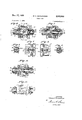
- Fig. 11 is a plan view of a unitv lock embodying the present invention.
- I Fig. 2 is a fragmentary plan view of said lock, partially in central horizontal section, illustrating the llock mechanism in'normal unlocked condition.
- Fig. 3 is an visometric view illustrating particular elements of the lock mechanism and the relative positions which 'they occupy in the lock.
- Fig. 4 is a fragmentary front view of the 1ock,""partially in central vertical section, further illustrating'the lock mechanism.
- Fig. 5 is a view similar to Fig. 4, but further illustrating 'the construction of the lock.
- Fig. '6 is a sectional end view taken on line A6--6 of Fig-4.
- i Y v "Figsr7, 8 .and 9 are vsectional end views of the lock taken, respectively, on lines 7--7, 8 8 and ⁇ '9-9of Fig. 4.
- LlFig. 1-0 is a fragmentary sectional front view'of vthe lockl illustrating the condition of the v'lock mechanism when both the inner andthe outer 'knobs are vdogged against operation.
- l Fig. 1'1 - is a fragmentary plan view further illustrating the .lock mechanism when in dogged condition.
- the housing 5 is :secured in said notch by inner and outer escutcheon plates 8 and 9 which are clamped against the opposite faces of the door by screws 10 which extend through the inner escutcheon plate 8 and are threaded to the outer plate 9.
- the housing 5 has a front wall 11 which is disposed flush with the edge of the door and elongated side walls 12-12 which extend rearwardly therefrom.
- a tubular knob shank bearing sleeve 13 extends transversely through said side walls adjacent the rear end of the housing and projects through openings in the inner and outer escutcheon plates.
- the bearing sleeve is secured to the housing by pins 14-14 which extend thereunto from a tie-bar 15 that is attached to the side walls 12-12.
- the portion of the bearing sleeve 13 ybetween the .side walls of the housing contains diametrically opposed clearance openings 16-16 which are located symetrically with respect to the vertical axis of the sleeve and from the outer edges of which there extend diametrically opposed locking notches 17-17 which are located centrally of the clearance openings. Similar notches also extend from the inner sides of the clearance openings since the bearing sleeveof the lock is a standard part which is used in all functions, but in the present embodiment the in ner locking notches are not used.
- the housing S carries a latch bolt 18 which is pivotalf 1y Vmounted thereon by a pin 19 and extends through an opening in the front wall 11.
- the latch bolt is con*- nected to a conventional retractor 20 which extends longitudinally of the housing and includes a yoke portion 20a which straddles the bearing sleeve 13 and has laterally extending arms 20b20b whose forward faces provide rollback platforms 2lic 2tlc.
- a further detailed description of the retractor is not believed necessary since its construction is conventional and it is Well understood that the retractor and the latch bolt are biased into normal position, as illustrated throughout the drawing, by a conventional compression spring.
- the lock mechanism is protected from dirt and other foreign matter by a dust cover 5a which is disposed over the open of' door locks without departing from'the spirit thereof.
- the knob shank bearing sleeve 13 rotatably supports inner and outer separate tubular knob Shanks 21 and 22 which are secured, respectively, to inner and outer knobs 23 and 24. Said knob Shanks are retained against axial movement by suitable locking keys 25-25, as clearly described in my copending application Serial No. 577,- 509, filed April 1l, 1956, andhave their inner ends in close proximity.
- the inner end of the inner knob shank 21 contains a pair of diametrically opposed, horizontally extending slots 26-26, and the adjacent end of the outer knob shank 22 contains a pair of similarly disposed slots 27-27 which are normally aligned with the slots 26426.
- the inner end of the outer shank also contains a pair of diametrically opposed vertically extending slots 28-28. It will be noted that the slots 28-28 extend to approximately the end of the locking notches 17-11 and are normally aligned therewtih.
- a pair of diametrically opposed arms 29e-29C extend radially and then perpendicularly from said central portion 29a and are adapted to t Within the slots .Z6- 26 and 27--27 in the inner and the outer knob shanks, respectively, t thereby prevent relative rotation of said shanks. It will thus be understood that the inner and the outer knob shanks rotate simultaneously upon rotation of either the inner or the outer knob.
- the retractor of the lock is actuated by a single rollback 30 which is non-rotatably carried by the outer knob shank, and, as best shown in Fig. 7, includes a circular hub portion 30a that is disposed within the bore of the outer knob shank and has diametrically opposed arms 3011-30!) extending therefrom through the slots ZS-ZS and through the clearance openings 16-16 to a position overlying the rollback platforms 20c-20c on the retractor.
- the inner and the outer knob shanks will be rotated simultaneously to thereby rotate the rollback 30 which will urge the retractor 20 and the latch bolt 18 into retracted position.
- the rollback 30 is adapted to slide axially in the outer knob shank from a normal position, as illustrated in Figs. 1 through 5, to a clogging position, as shown in Figs. 10 and ll, wherein the arms 30h-3% thereof are disposed in the locking notches 1'7--17- In this position, rotation of the rollback is prevented and the outer knob shank is thereby dogged against operation. Since the inner knob shank is connected to the outer knob shank through the coupling member 29, rotation of the inner knob shank is also prevented, and it will be understood that upon movement of the rollback into clogging position both the inner and the outer knob shanks are simultaneously dogged against operation.
- a spindle 31 which is disposed axially of the knob shanks and extends through an axial opening 30C in the rollback and through the opening 29a in the coupling member 29.
- the said spindle is adapted to rotate relatively to the rollback, but is secured against axial movement with respect thereto by suitable locking rings 32-32.
- the inner knob 23 contains a conventional cylinder lock 33 having a rotatable key-plug 34 which projects through an opening in the wall of the knob.
- a tubular cam 35 is secured to the inner end of the key-plug 34 by a pin 36 and is mounted for rotation in the inner knob shank 21.
- the inner end of the spindle 31 extends into the cam 35 and is both rotatable and axially slidable relatively thereto.
- the cam is provided with a cam slot 37 which receives a cam follower pin 38 extending radially from the spindle 31.
- a similar cylinder lock 39 is carried by the outer knob 24 and said cylinder lock also contains a rotatable keyplug 40 which projects through an opening in the Wall of the knob.
- a tubular driver 41 is secured to the inner end of the key-plug 40 by a pin 42 and is mounted for rotation in the outer knob shank 22.
- the outer end of the spindle 31 extends into the driver and is also both rotatable and axially slidable relatively thereto.
- the driver has a semi-circular extension 43 having abutment surfaces 44 and 44a at its opposite ends which are adapted to engage with a pin 45 extending radially from the spindle which provide a lost motion connection permitting 180 relative rotation between the spindle and the driver. It will be understood that the cam 35 and the driver 41 are normally prevented from rotating relatively to their respective knob shanks by the pin tumblers contained Within the cylinder locks.
- the coupling member 29 is retained in xed position relatively to the knob shanks and the spindle by a compression spring 46 in the inner knob shank which surrounds the spindle and is disposed between said coupling member and the end of the cam 35 and urges the arms of the coupling member into the slots in lthe outer knob shank.
- the above described mechanism permits simultaneous clogging or undogging of the inner and the outer knobs of the lock from either side of the door.
- the proper key is inserted into the key plug 34 projecting from the inner knob and said plug is turned 360 in a counterclockwise direction which causes a similar movement of the cam 35, It will be noted from Figs. 2 and 4 through 6 that the spindle 31 can rotate from normal position for 180 in a counterclockwise direction relatively to the driver 41 or until the pin 45 projecting from the spindle engages the abutment surface 44a thereon so that the spindle will rotate with the cam during 180 of its movement.
- the inner and the outer knobs may be undogged from the inner side of the door by rotating the cam 360 in a clockwise direction which will cause a movement of the spindle and the rollback in reverse of that above described and will return the mechanism to the position shown in Fig. 2.
- the knobs may be undogged from the outer side of the door by rotating the driver 41. with a suitable key for 360 in a clockwise direction from the position shown in Figs. l0 and 11.
- the driver will rotate relatively to the spindle for 180, but during the remaining 180 of rotation, the driver will rotate the spindle relatively to the then stationary cam 35 to thereby cause axial movement of the spindle toward the inner knob and shifting of the rollback out of the locking notches 17-17.
- My improved mechanism also permits dogging and undogging of the knobs from the outer side of the door by merely rotating the driver in the proper directions to cause rotation of the spindle 31 relatively to the stationary cam member 35, which results in axial movement of the spindle and the rollback into and out of clogging position in a manner which will be readily understood from the above description.
- my invention provides a mechanism for so-called store-door locks which is much less complicated and less expensive to produce than mechanisms having a similar function heretofore available.
- a door lock comprising a housing, a retractor for a latch bolt movable in said housing, separate inner and outer tubular knob shanks mounted to rotate in said housing and each having a knob secured thereto, the inner ends of said shanks having opposed pairs of slots extending longitudinally thereinto, a coupling member having a central portion disposed within one of said shanks and a pair of opposed arms extending therefrom adapted to be received in said slots and preventing relative rotation of said shanks, rollback means associated with at least one of said shanks for actuating said retractor upon rotation of said knob shanks by either of said knobs, clogging means movable into interengagement with one of said shanks and said housing to thereby prevent rotation of both of said shanks by either of said knobs, and means operable from at least one of said knobs for shifting said dogging means into and out of clogging position.
- a door lock comprising a housing having a recess therein, a retractor for a latch bolt movable in said housing, separate inner and outer tubular knob Shanks mounted to rotate in said housing and each having a knob secured thereto, each of Said Shanks having a pair of slots extending longitudinally into its inner end which are algnable with the Slots in the inner end of the opposite shank, a U-shaped coupling member having a circular central portion fitting within one of said Shanks and a pair of arms extending from Said central portion into said slots and preventing relative rotation of Said knob Shanks, a rollback member non-rotatably connected to one of said Shanks and adapted to actuate said retractor upon rotation of either of said knobs, Said rollback member being shiftable axially of its shank and having portions adapted to be received in said recess ro thereby dog Said Shanks against rotation by either of Said knobs, a rotatable and axially movable spindle member
- a housing having separate inner and outer tubular knob Shanks mounted to ro ate therein, each of said Shanks having a pair of slots in its inner end which are algnable with the Slots in the inner end of the opposite shank, and a U-shaped coupling member including a circular central portion disposed within the inner end of one of said Shanks and having a pair of arms extending therefrom into the slots in Said knob Shanks to prevent relative rotation thereof.
Landscapes
- Lock And Its Accessories (AREA)
Description
Nov. 17, 1959 w. v. scHwEn'zER Filed Oct. 8, 1956 2 Sheets-Sheet 1 a-ffy, 2.
Nov. 17, 1959 w. v. sczHwElTzER I DOOR LOCK Filed Oct. 8, 1956 asheets-Sheetz K ity" .5I /Z United States Patent DOOR LOCK William V. Schweitzer, New Britain, Conn., assignor to The American Hardware Corporation, New Britain, Conn., a corporation of Connecticut Application October 8, 1956, Serial No. 614,730 3 Claims. (Cl. 70-216) ,lfhis invention relates to a' door Ilock 'and vmore particularly to-a door lock of the v.so-called unittype .which 4isprimarily intended for use on the entrance doors of rstor'esand the like.
:The primary :object of this invention is to provide a unit llock having inner yand outer knobs which may be .simultaneously ,locked and. unlocked by key operated means contained in rboth Vof said knobs, and in which said knobs-:may be simultaneously locked `by the key operated meansr in either one of the knobs and -simul- .taneously unlocked `by the key operated means convtained in Jthe opposite knob.
A further object of :this invention is "to provide `a `mechanism which will function inthe manner above describedand is :simple in construction.
Another object of this invention is to provide a mechanisrn which .is .adapted for use with the parts ofthe flock ycommon to al1 other functions.
Further objects and advantages of "this invention will -be more clearly understood fromrthe following description `and the accompanying drawings in which: i
"Fig. 11 "is a plan view of a unitv lock embodying the present invention. I Fig. 2 is a fragmentary plan view of said lock, partially in central horizontal section, illustrating the llock mechanism in'normal unlocked condition.
Fig. 3 is an visometric view illustrating particular elements of the lock mechanism and the relative positions which 'they occupy in the lock. i
Fig. 4 is a fragmentary front view of the 1ock,""partially in central vertical section, further illustrating'the lock mechanism. v l
Fig. 5 is a view similar to Fig. 4, but further illustrating 'the construction of the lock.
Fig. '6 is a sectional end view taken on line A6--6 of Fig-4. i Y v "Figsr7, 8 .and 9 are vsectional end views of the lock taken, respectively, on lines 7--7, 8 8 and` '9-9of Fig. 4.
LlFig. 1-0 is a fragmentary sectional front view'of vthe lockl illustrating the condition of the v'lock mechanism when both the inner andthe outer 'knobs are vdogged against operation. l Fig. 1'1 -is a fragmentary plan view further illustrating the .lock mechanism when in dogged condition.
-In this `.application I lhave chosen to illustrate my invention as embodied'in the' basic unit lock housing originally disclosed Ain my copending application Serial No. 498,525, filed April'l, 1955, and now Patent No. 2,821,849, issuedv February 4, 1958 but it will =be readily understood lthat said invention is applicable to other types ice which are not shown in detail are conventional and will lbe readily understood.
Referring now to Fig. l of the drawings, the numeral =5 indicates the housing of the lock which is adapted to carry the entire lock mechanism and is received in a notch 6 extending into the edge of a door 7 in the manner characteristic of all unit locks. The housing 5 is :secured in said notch by inner and outer escutcheon plates 8 and 9 which are clamped against the opposite faces of the door by screws 10 which extend through the inner escutcheon plate 8 and are threaded to the outer plate 9. ,The housing 5 has a front wall 11 which is disposed flush with the edge of the door and elongated side walls 12-12 which extend rearwardly therefrom. A tubular knob shank bearing sleeve 13 extends transversely through said side walls adjacent the rear end of the housing and projects through openings in the inner and outer escutcheon plates. The bearing sleeve is secured to the housing by pins 14-14 which extend thereunto from a tie-bar 15 that is attached to the side walls 12-12. The portion of the bearing sleeve 13 ybetween the .side walls of the housing contains diametrically opposed clearance openings 16-16 which are located symetrically with respect to the vertical axis of the sleeve and from the outer edges of which there extend diametrically opposed locking notches 17-17 which are located centrally of the clearance openings. Similar notches also extend from the inner sides of the clearance openings since the bearing sleeveof the lock is a standard part which is used in all functions, but in the present embodiment the in ner locking notches are not used.
v The housing S carries a latch bolt 18 which is pivotalf 1y Vmounted thereon by a pin 19 and extends through an opening in the front wall 11. The latch bolt is con*- nected to a conventional retractor 20 which extends longitudinally of the housing and includes a yoke portion 20a which straddles the bearing sleeve 13 and has laterally extending arms 20b20b whose forward faces provide rollback platforms 2lic 2tlc. A further detailed description of the retractor is not believed necessary since its construction is conventional and it is Well understood that the retractor and the latch bolt are biased into normal position, as illustrated throughout the drawing, by a conventional compression spring. The lock mechanism is protected from dirt and other foreign matter by a dust cover 5a which is disposed over the open of' door locks without departing from'the spirit thereof. M
Construction and operation ofthose portions of the lock y sides'of the housing.
The knob shank bearing sleeve 13 rotatably supports inner and outer separate tubular knob Shanks 21 and 22 which are secured, respectively, to inner and outer knobs 23 and 24. Said knob Shanks are retained against axial movement by suitable locking keys 25-25, as clearly described in my copending application Serial No. 577,- 509, filed April 1l, 1956, andhave their inner ends in close proximity. The inner end of the inner knob shank 21 contains a pair of diametrically opposed, horizontally extending slots 26-26, and the adjacent end of the outer knob shank 22 contains a pair of similarly disposed slots 27-27 which are normally aligned with the slots 26426. The inner end of the outer shank also contains a pair of diametrically opposed vertically extending slots 28-28. It will be noted that the slots 28-28 extend to approximately the end of the locking notches 17-11 and are normally aligned therewtih.
In order for. the lock to function in the prescribed manner, `relative rotation of the innerv and the outer knobs must be prevented. This could conceivably be accomplished by the use of a single, one-piece, knob shank instead of the separate Shanks 21 and 22. However, since the Shanks 21 and 22 are standard parts adapted for use in locks having other functions, their use in the present structure is much preferred and relative rotation therebetween is prevented by a U-shaped coupling member 29 which connects said shanks together. Said coupling member includes a circular central portion 29a which is adapted to fit within the bore of the inner knob shank and is provided with an axial hole 29h. A pair of diametrically opposed arms 29e-29C extend radially and then perpendicularly from said central portion 29a and are adapted to t Within the slots .Z6- 26 and 27--27 in the inner and the outer knob shanks, respectively, t thereby prevent relative rotation of said shanks. It will thus be understood that the inner and the outer knob shanks rotate simultaneously upon rotation of either the inner or the outer knob.
The retractor of the lock is actuated by a single rollback 30 which is non-rotatably carried by the outer knob shank, and, as best shown in Fig. 7, includes a circular hub portion 30a that is disposed within the bore of the outer knob shank and has diametrically opposed arms 3011-30!) extending therefrom through the slots ZS-ZS and through the clearance openings 16-16 to a position overlying the rollback platforms 20c-20c on the retractor. When either the inner or the outer knob is rotated in either direction, the inner and the outer knob shanks will be rotated simultaneously to thereby rotate the rollback 30 which will urge the retractor 20 and the latch bolt 18 into retracted position.
The rollback 30 is adapted to slide axially in the outer knob shank from a normal position, as illustrated in Figs. 1 through 5, to a clogging position, as shown in Figs. 10 and ll, wherein the arms 30h-3% thereof are disposed in the locking notches 1'7--17- In this position, rotation of the rollback is prevented and the outer knob shank is thereby dogged against operation. Since the inner knob shank is connected to the outer knob shank through the coupling member 29, rotation of the inner knob shank is also prevented, and it will be understood that upon movement of the rollback into clogging position both the inner and the outer knob shanks are simultaneously dogged against operation.
In order to move the rollback into and out of dogging position, I have provided a spindle 31 which is disposed axially of the knob shanks and extends through an axial opening 30C in the rollback and through the opening 29a in the coupling member 29. The said spindle is adapted to rotate relatively to the rollback, but is secured against axial movement with respect thereto by suitable locking rings 32-32.
The inner knob 23 contains a conventional cylinder lock 33 having a rotatable key-plug 34 which projects through an opening in the wall of the knob. A tubular cam 35 is secured to the inner end of the key-plug 34 by a pin 36 and is mounted for rotation in the inner knob shank 21. The inner end of the spindle 31 extends into the cam 35 and is both rotatable and axially slidable relatively thereto. The cam is provided with a cam slot 37 which receives a cam follower pin 38 extending radially from the spindle 31.
A similar cylinder lock 39 is carried by the outer knob 24 and said cylinder lock also contains a rotatable keyplug 40 which projects through an opening in the Wall of the knob. A tubular driver 41 is secured to the inner end of the key-plug 40 by a pin 42 and is mounted for rotation in the outer knob shank 22. The outer end of the spindle 31 extends into the driver and is also both rotatable and axially slidable relatively thereto. The driver has a semi-circular extension 43 having abutment surfaces 44 and 44a at its opposite ends which are adapted to engage with a pin 45 extending radially from the spindle which provide a lost motion connection permitting 180 relative rotation between the spindle and the driver. It will be understood that the cam 35 and the driver 41 are normally prevented from rotating relatively to their respective knob shanks by the pin tumblers contained Within the cylinder locks.
The coupling member 29 is retained in xed position relatively to the knob shanks and the spindle by a compression spring 46 in the inner knob shank which surrounds the spindle and is disposed between said coupling member and the end of the cam 35 and urges the arms of the coupling member into the slots in lthe outer knob shank.
The above described mechanism permits simultaneous clogging or undogging of the inner and the outer knobs of the lock from either side of the door.
If it is desired to lock the door from the inside, the proper key is inserted into the key plug 34 projecting from the inner knob and said plug is turned 360 in a counterclockwise direction which causes a similar movement of the cam 35, It will be noted from Figs. 2 and 4 through 6 that the spindle 31 can rotate from normal position for 180 in a counterclockwise direction relatively to the driver 41 or until the pin 45 projecting from the spindle engages the abutment surface 44a thereon so that the spindle will rotate with the cam during 180 of its movement. After the pin 41 engages the abutment surface 44a, however, further rotation of the spindle is prevented and the cam 35 will rotate relatively thereto for 180 to cam the spindle and the rollback axially toward the outer knob and shift the arms of the rollback into the locking notches 17-17 as illustrated in Figs. 10 and 11. In this position, rotation of both the inner and the outer knob shanks is prevented.
The inner and the outer knobs may be undogged from the inner side of the door by rotating the cam 360 in a clockwise direction which will cause a movement of the spindle and the rollback in reverse of that above described and will return the mechanism to the position shown in Fig. 2.
If desired, the knobs may be undogged from the outer side of the door by rotating the driver 41. with a suitable key for 360 in a clockwise direction from the position shown in Figs. l0 and 11. The driver will rotate relatively to the spindle for 180, but during the remaining 180 of rotation, the driver will rotate the spindle relatively to the then stationary cam 35 to thereby cause axial movement of the spindle toward the inner knob and shifting of the rollback out of the locking notches 17-17.
My improved mechanism also permits dogging and undogging of the knobs from the outer side of the door by merely rotating the driver in the proper directions to cause rotation of the spindle 31 relatively to the stationary cam member 35, which results in axial movement of the spindle and the rollback into and out of clogging position in a manner which will be readily understood from the above description.
It will thus be seen, that my invention provides a mechanism for so-called store-door locks which is much less complicated and less expensive to produce than mechanisms having a similar function heretofore available.
1. A door lock comprising a housing, a retractor for a latch bolt movable in said housing, separate inner and outer tubular knob shanks mounted to rotate in said housing and each having a knob secured thereto, the inner ends of said shanks having opposed pairs of slots extending longitudinally thereinto, a coupling member having a central portion disposed within one of said shanks and a pair of opposed arms extending therefrom adapted to be received in said slots and preventing relative rotation of said shanks, rollback means associated with at least one of said shanks for actuating said retractor upon rotation of said knob shanks by either of said knobs, clogging means movable into interengagement with one of said shanks and said housing to thereby prevent rotation of both of said shanks by either of said knobs, and means operable from at least one of said knobs for shifting said dogging means into and out of clogging position. l
2. A door lock comprising a housing having a recess therein, a retractor for a latch bolt movable in said housing, separate inner and outer tubular knob Shanks mounted to rotate in said housing and each having a knob secured thereto, each of Said Shanks having a pair of slots extending longitudinally into its inner end which are algnable with the Slots in the inner end of the opposite shank, a U-shaped coupling member having a circular central portion fitting within one of said Shanks and a pair of arms extending from Said central portion into said slots and preventing relative rotation of Said knob Shanks, a rollback member non-rotatably connected to one of said Shanks and adapted to actuate said retractor upon rotation of either of said knobs, Said rollback member being shiftable axially of its shank and having portions adapted to be received in said recess ro thereby dog Said Shanks against rotation by either of Said knobs, a rotatable and axially movable spindle member contained within said Shanks and extending through openings in said coupling member and said rollback, means securing said rollback to Said spindle member for axial movement therewith, a cylinder lock contained in each of said knobs, cam means controlled by the cylinder lock in one of said knobs for moving said spindle and rollback into and out of dogging position, and driver means controlled by the cylinder lock in the other of Said knobs adapted to rotate said spindle relatively to said cam means to cause movement of said spindle and the rollback into and out of dogging position.
3. In a door lock, a housing having separate inner and outer tubular knob Shanks mounted to ro ate therein, each of said Shanks having a pair of slots in its inner end which are algnable with the Slots in the inner end of the opposite shank, and a U-shaped coupling member including a circular central portion disposed within the inner end of one of said Shanks and having a pair of arms extending therefrom into the slots in Said knob Shanks to prevent relative rotation thereof.
References Cited in the le of this patent UNITED STATES PATENTS 626,341 Phelps June 6, 1899 971,340 Arens Sept. 27, 1910 1,395,414 I-luiman Nov. l, 1921
Priority Applications (1)
| Application Number | Priority Date | Filing Date | Title |
|---|---|---|---|
| US614730A US2912846A (en) | 1956-10-08 | 1956-10-08 | Door lock |
Applications Claiming Priority (1)
| Application Number | Priority Date | Filing Date | Title |
|---|---|---|---|
| US614730A US2912846A (en) | 1956-10-08 | 1956-10-08 | Door lock |
Publications (1)
| Publication Number | Publication Date |
|---|---|
| US2912846A true US2912846A (en) | 1959-11-17 |
Family
ID=24462479
Family Applications (1)
| Application Number | Title | Priority Date | Filing Date |
|---|---|---|---|
| US614730A Expired - Lifetime US2912846A (en) | 1956-10-08 | 1956-10-08 | Door lock |
Country Status (1)
| Country | Link |
|---|---|
| US (1) | US2912846A (en) |
Cited By (6)
| Publication number | Priority date | Publication date | Assignee | Title |
|---|---|---|---|---|
| US6626018B2 (en) * | 2001-01-29 | 2003-09-30 | Sargent Manufacturing Company | High strength lever handle lock mechanism |
| US20040070219A1 (en) * | 2002-10-15 | 2004-04-15 | Sargent Manufacturing Company | Enhanced security catch assembly for retaining a handle on a spindle |
| WO2004015229A3 (en) * | 2002-08-12 | 2004-08-05 | Sargent Mfg Co | Security classroom function lock mechanism |
| US20060055183A1 (en) * | 2004-09-13 | 2006-03-16 | Wheatland Graham J | Push button lock mechanism for a handle set |
| US20160108642A1 (en) * | 2014-10-20 | 2016-04-21 | Assa Abloy Australia Pty Limited | Cylinder lock |
| US20170183892A1 (en) * | 2015-12-28 | 2017-06-29 | Oviku Oy | Security door lock |
Citations (3)
| Publication number | Priority date | Publication date | Assignee | Title |
|---|---|---|---|---|
| US626341A (en) * | 1899-06-06 | phelps | ||
| US971340A (en) * | 1909-11-27 | 1910-09-27 | P & F Corbin | Entrance-door lock. |
| US1395414A (en) * | 1921-11-01 | L huffman |
-
1956
- 1956-10-08 US US614730A patent/US2912846A/en not_active Expired - Lifetime
Patent Citations (3)
| Publication number | Priority date | Publication date | Assignee | Title |
|---|---|---|---|---|
| US626341A (en) * | 1899-06-06 | phelps | ||
| US1395414A (en) * | 1921-11-01 | L huffman | ||
| US971340A (en) * | 1909-11-27 | 1910-09-27 | P & F Corbin | Entrance-door lock. |
Cited By (16)
| Publication number | Priority date | Publication date | Assignee | Title |
|---|---|---|---|---|
| NO337572B1 (en) * | 2001-01-29 | 2016-05-09 | Sargent Mfg Co | High-strength locking mechanism for use with lever handles |
| EP1356176A4 (en) * | 2001-01-29 | 2009-02-18 | Sargent Mfg Co | High strength lever handle lock mechanism |
| US6735993B2 (en) | 2001-01-29 | 2004-05-18 | Sargent Manufacturing Company | High strength lever handle lock mechanism |
| US6626018B2 (en) * | 2001-01-29 | 2003-09-30 | Sargent Manufacturing Company | High strength lever handle lock mechanism |
| US6860129B2 (en) | 2001-01-29 | 2005-03-01 | Sargent Manufacturing Company | Security classroom function lock mechanism |
| CN100366859C (en) * | 2002-08-12 | 2008-02-06 | 萨金特制造公司 | Safe Classroom Function Lock Mechanism |
| WO2004015229A3 (en) * | 2002-08-12 | 2004-08-05 | Sargent Mfg Co | Security classroom function lock mechanism |
| US6908126B2 (en) | 2002-10-15 | 2005-06-21 | Sargent Manufacturing Company | Enhanced security catch assembly for retaining a handle on a spindle |
| US20040070219A1 (en) * | 2002-10-15 | 2004-04-15 | Sargent Manufacturing Company | Enhanced security catch assembly for retaining a handle on a spindle |
| US7178842B2 (en) * | 2004-09-13 | 2007-02-20 | Newfrey, Llc | Push button lock mechanism for a handle set |
| WO2006031655A3 (en) * | 2004-09-13 | 2006-11-30 | Newfrey Llc | Push button lock mechanism for a handle set |
| US20060055183A1 (en) * | 2004-09-13 | 2006-03-16 | Wheatland Graham J | Push button lock mechanism for a handle set |
| US20160108642A1 (en) * | 2014-10-20 | 2016-04-21 | Assa Abloy Australia Pty Limited | Cylinder lock |
| US9951544B2 (en) * | 2014-10-20 | 2018-04-24 | Assa Abloy Australia Pty Ltd | Cylinder lock |
| US20170183892A1 (en) * | 2015-12-28 | 2017-06-29 | Oviku Oy | Security door lock |
| US9797161B2 (en) * | 2015-12-28 | 2017-10-24 | Oviku Oy | Security door lock |
Similar Documents
| Publication | Publication Date | Title |
|---|---|---|
| US3750433A (en) | Mortise lock retract mechanism | |
| US4899561A (en) | Pop-out handle lock assembly | |
| US5657652A (en) | Pin tumbler cabinet door and drawer deadlocking latch-lock | |
| US7874189B2 (en) | Field-reversible cabinet latch lock | |
| US5219196A (en) | Locks | |
| US4573334A (en) | Deadbolt lock adjustable for mounting in doors of various thicknesses | |
| US3345838A (en) | Double sliding door lock | |
| EP0159356A4 (en) | Latch lock mechanism. | |
| US2743600A (en) | Tubular lock | |
| US2912846A (en) | Door lock | |
| US3604229A (en) | Dead bolt and latch door lock | |
| US2303624A (en) | Door lock | |
| US4578967A (en) | Combined door latch and deadbolt arrangement | |
| US2636376A (en) | Lock | |
| US2697342A (en) | Lock mechanism | |
| US2124897A (en) | Door lock | |
| US4617811A (en) | Mechanism for operating a drop-bolt door lock | |
| US3128618A (en) | Key shut out for locks | |
| US5551263A (en) | Lock with dead bolt camming action on 90 degree lock cylinder rotation | |
| US2208003A (en) | Compartment door latch | |
| US3368375A (en) | Removable core with indicator pin | |
| US3186747A (en) | Deadlocking latch for house trailers | |
| US2632664A (en) | Door lock | |
| GB1210831A (en) | Improvements relating to door lock and latch assemblies | |
| US2959952A (en) | Door lock |