US2600652A - Control switch - Google Patents
Control switch Download PDFInfo
- Publication number
- US2600652A US2600652A US59937A US5993748A US2600652A US 2600652 A US2600652 A US 2600652A US 59937 A US59937 A US 59937A US 5993748 A US5993748 A US 5993748A US 2600652 A US2600652 A US 2600652A
- Authority
- US
- United States
- Prior art keywords
- housing
- switch
- cam
- pair
- contacts
- Prior art date
- Legal status (The legal status is an assumption and is not a legal conclusion. Google has not performed a legal analysis and makes no representation as to the accuracy of the status listed.)
- Expired - Lifetime
Links
- 238000010438 heat treatment Methods 0.000 description 11
- 239000011324 bead Substances 0.000 description 4
- 230000000694 effects Effects 0.000 description 2
- 238000009413 insulation Methods 0.000 description 2
- 239000003973 paint Substances 0.000 description 2
- 238000000926 separation method Methods 0.000 description 2
- 239000000853 adhesive Substances 0.000 description 1
- 230000001070 adhesive effect Effects 0.000 description 1
- 239000011248 coating agent Substances 0.000 description 1
- 238000000576 coating method Methods 0.000 description 1
- 238000010276 construction Methods 0.000 description 1
- 230000000994 depressogenic effect Effects 0.000 description 1
- 230000000717 retained effect Effects 0.000 description 1
Images

Classifications
-
- H—ELECTRICITY
- H01—ELECTRIC ELEMENTS
- H01H—ELECTRIC SWITCHES; RELAYS; SELECTORS; EMERGENCY PROTECTIVE DEVICES
- H01H9/00—Details of switching devices, not covered by groups H01H1/00 - H01H7/00
- H01H9/02—Bases, casings, or covers
- H01H9/0214—Hand-held casings
- H01H9/0228—Line cord switches
Definitions
- My present invention relates to a control switch which may be used in connection with a heating pad or other electrical appliance, the present application being a division of my copending application, Serial No. 743,676, filed April 24, 1947.
- One object of the invention is to provide a control switch of novel character having a simple arrangement of first and second switches and a cam to open both switches, close one and open the other, close the other and open the one, or close both switches, as desired.
- Another object is to provide a detent means for holding the cam which operates the first and second switches in their various positions of adjustmen-t.
- my invention consists in the construction, arrangement and combination of the various parts of my device whereby the objects contemplated are attained, as hereinafter more fully set forth, pointed out in my claims and illustrated in the accompanying drawings, wherein:
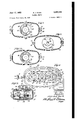
- FIG. 1 is a plan view of a switch structure embodying my invention
- Figure la is a similar view showing a modified form of the structure
- Figure 2 is a similar view with the control knob removed and the control shaft shown in end View; I v
- Figure 3 is an enlarged sectional view on theline 3-3 of Figure 1 Figure 4. is a sectional View on the line 44 of Figure 3 showing the switch mechanism within the housing and illustrating diagrammatically a heating pad connected in circuit therewith to illustrate one use for the switch;
- Figure 5' is a sectional View on the line 55 of Figure 3 showing a detent means for holding the switch in various adjusted positions;
- Figures 6, 7' and 8 are diagrammatic views showing, respectively, the position of the switch for low, medium and high heat in" the heating pad.
- the contacts l9 and 2f are mounted on a bracket 15 which is connected with a supply wire 25.
- a second supply wire 2! and the supply wire 25 are connected to a service cord plug 29.
- Feed wires 28 and 3p extend from the brackets It and IT to the ends of a heatingelement having sections HE ⁇ and HF]. These heating element sections may be within a heating pad P, or may be heating elements or other types of electrically energized devices ine1ectri cal appliances or the like, wherever it is desirable to energize one, the other, or both.
- the supply wire 2'! extends through the housing Ni -l2 and connects with a center tap of the heating elementsHE and HE A cam C is provided for operating.
- the switches S and S the cam having shaft like extensions 34 and 35 journalled respectively in a hOlQ BS of the cover l2 and a socket 31 of the housing bottom it.
- the cam hasfa detent wheel 38 formedthereon, with which' leaf springdetent arms 33 coact for positioning purposes shown in Figure 5.
- the cam C h'as four depressed sections indicated as 3 and diadaptedto coact with the switcharms QZ-and 24, in"' various positions of adjustment, as will hereinafter appear.
- I For operating the cam C, I provide a control knob 39 secured thereto asby a set screw 42. T e p r rt i h s s; a pa -9i sto hiss 3' a 5 t ere t wi hyd t e r si e lug 4-1 for the purpose of limiting rotation of the knob to approximatel yllifii I I I I I I
- the coating is a luminous paint or strip of luminous adhesive so that it can be readily seen at night, this being particularly desirable in connection with a heating pad.
- the flange 40 it will be obvious, can completely cover the illuminated area 4
- the luminous area is shown as consisting of a plurality of small areas 41a so that the number of them can be counted in the dark and the position of the control switch thereby determined, whereas with the arrangement shown in Figure l the user can determine the position of the switch by noting the amount of the luminous area uncovered, that is one-third, two-thirds, or all of it.
- the position indicating means just described is claimed in my parent application.
- Strain relief is provided for the wires 26, 21, 28 and 30 in the form of raised beads 50 and 52 in the notches 54 and 55 of the housing bottom member ID.
- the housing top member I2 is similarly treated and accordingly when the two halves of the housing are clamped together by the screws M, the beads 50 and 52 bite into the insulation on the wires to prevent them from longitudinal movement after the housing is closed.
- the beads of the two halves of the housing are preferably ofiset in relation to each other for the purpose of providing offset jaws to grip the wire for strain relief and at the same time prevent cutting the insulation as would be the case if the beads were in alignment with each other.
- the heating element HE is energized by adjusting the switches to the position shown in Figure 7 with the cam notch 3 receiving the switch arm 22.
- both heating elements are energized by closing both switches S and S This is accomplished by adjusting the cam C to the position of Figure 8 wherein the notches 2 and 4 receive the switch arms 24 and 22 and thereby permit closure of both switches.
- a housing a contact bracket therein adjacent one end thereof and having a pair of contacts, a pair of circuit wires extending into one end of said housing and one thereof being connected to said contact bracket, the other thereof extending through said housing and from the opposite end thereof, a pair of current carrying brackets in said housing adjacent said opposite end thereof, circuit wires extending therefrom and out of said opposite end of said housing, a leaf spring carried by each of said pair of current carrying brackets and each biased to engage one of said pair of contacts, a cam in said housing intermediate said brackets and cooperating with said leaf springs to separate them from said pair of contacts, said cams having three lobes around the cam axis to effect such separation and three notches between said lobes to permit engagement of said leaf springs with said pair of contacts, two of said lobes and notches being of substantially extent and the third lobe and notch of substantially extent whereby in substantially 90 of rotation and three positions spaced substantially 45 apart of said cam, said leaf springs are selective
- a housing a contact bracket therein adjacent one end thereof and having a pair of contacts, a pair of circuit wires extending into one end of said housing and one thereof being connected to said contact bracket, the other thereof extending through said housing and from the opposite end thereof, a pair of current carrying brackets in said housing adjacent said opposite end thereof, circuit wires extending therefrom and out of said opposite end of said housing, a leaf spring carried by each of said pair of current carrying brackets and each biased to engage one of said pair of contacts, a cam in said housing intermediate said brackets and cooperating with said leaf springs to separate them from said pair of contacts, said cams having three lobes around the cam axis to effect such separation and three notches between said lobes to permit engagement of said leaf springs with said pair of contacts, two of said lobes and notches being of substantially 45 extent and the third lobe and notch of substantially 90 extent whereby in substantially of rotation and four positions spaced substantially 45 apart of said cam, said leaf springs are
Landscapes
- Rotary Switch, Piano Key Switch, And Lever Switch (AREA)
Description
J1me 1952 A. J. HUCK 2,600,652
comaor. swnrcu Original Filed April 24, 1947 2 SHEETS--SHEET l June 17, 1952 A. J. HUCK 2,600,652
CONTROL SWITCH Original Filed April 24, 1947 2 SHEETSSHEET 2 Patented June 17, 1952.
UNITED STATES PATENT OFFICE tion of Delaware original application April 24, 1947, Serial No.
743,676. Divided and this application November 13', 1948, Serial No. 59,937
2 Claims.
My present invention relates to a control switch which may be used in connection with a heating pad or other electrical appliance, the present application being a division of my copending application, Serial No. 743,676, filed April 24, 1947.
One object of the invention is to provide a control switch of novel character having a simple arrangement of first and second switches and a cam to open both switches, close one and open the other, close the other and open the one, or close both switches, as desired.
Another object is to provide a detent means for holding the cam which operates the first and second switches in their various positions of adjustmen-t.
With these and other objects in view, my invention consists in the construction, arrangement and combination of the various parts of my device whereby the objects contemplated are attained, as hereinafter more fully set forth, pointed out in my claims and illustrated in the accompanying drawings, wherein:
Figure 1 is a plan view of a switch structure embodying my invention;
Figure la is a similar view showing a modified form of the structure;
Figure 2 is a similar view with the control knob removed and the control shaft shown in end View; I v
Figure 3 is an enlarged sectional view on theline 3-3 of Figure 1 Figure 4. is a sectional View on the line 44 of Figure 3 showing the switch mechanism within the housing and illustrating diagrammatically a heating pad connected in circuit therewith to illustrate one use for the switch;
Figure 5' is a sectional View on the line 55 of Figure 3 showing a detent means for holding the switch in various adjusted positions; and
Figures 6, 7' and 8 are diagrammatic views showing, respectively, the position of the switch for low, medium and high heat in" the heating pad.
On the accompanying drawings I have used the reference numerals I0 and 12" to indicate a a pair of brackets l6 and ll attached to a boss ll by terminal screws 28 and 30 The brack ets l5 and I! have leaf springswitch arms 22 and E i extending therefrom. The switch arms 22 and 24 carry contacts lt and 2B which are normally engaged with stationary contacts l9 and 2! on a bracket [5 due to inherent tendency of the leaf springs 22 and 24 to move toward each other from the position shown in Figure 6.
The contacts l9 and 2f are mounted on a bracket 15 which is connected with a supply wire 25. A second supply wire 2! and the supply wire 25 are connected to a service cord plug 29. Feed wires 28 and 3p extend from the brackets It and IT to the ends of a heatingelement having sections HE} and HF]. These heating element sections may be within a heating pad P, or may be heating elements or other types of electrically energized devices ine1ectri cal appliances or the like, wherever it is desirable to energize one, the other, or both. The supply wire 2'! extends through the housing Ni -l2 and connects with a center tap of the heating elementsHE and HE A cam C is provided for operating. the switches S and S the cam having shaft like extensions 34 and 35 journalled respectively in a hOlQ BS of the cover l2 and a socket 31 of the housing bottom it. The cam hasfa detent wheel 38 formedthereon, with which' leaf springdetent arms 33 coact for positioning purposes shown in Figure 5. The cam C h'as four depressed sections indicated as 3 and diadaptedto coact with the switcharms QZ-and 24, in"' various positions of adjustment, as will hereinafter appear. a V
For operating the cam C, I provide a control knob 39 secured thereto asby a set screw 42. T e p r rt i h s s; a pa -9i sto hiss 3' a 5 t ere t wi hyd t e r si e lug 4-1 for the purpose of limiting rotation of the knob to approximatel yllifii I I I For indicating theposition of the switch I: provide a flange t0 partiallyaround the' control knob 39, and an area G llon the switch cover [2, which area is arcuate, as" shown" in" Figure 2; and is coated with paint'or the like, having color which is clearly distinguishable from the flange 483. Freferably, the coating is a luminous paint or strip of luminous adhesive so that it can be readily seen at night, this being particularly desirable in connection with a heating pad. The flange 40, it will be obvious, can completely cover the illuminated area 4| when the switch is adiusted to the off position of Figure 6, and will variably uncover the luminous area at other positions of adjustment, for instance at.low position in Figure 1. In Figure 1a the luminous area is shown as consisting of a plurality of small areas 41a so that the number of them can be counted in the dark and the position of the control switch thereby determined, whereas with the arrangement shown in Figure l the user can determine the position of the switch by noting the amount of the luminous area uncovered, that is one-third, two-thirds, or all of it. The position indicating means just described is claimed in my parent application.
Strain relief is provided for the wires 26, 21, 28 and 30 in the form of raised beads 50 and 52 in the notches 54 and 55 of the housing bottom member ID. The housing top member I2 is similarly treated and accordingly when the two halves of the housing are clamped together by the screws M, the beads 50 and 52 bite into the insulation on the wires to prevent them from longitudinal movement after the housing is closed. The beads of the two halves of the housing are preferably ofiset in relation to each other for the purpose of providing offset jaws to grip the wire for strain relief and at the same time prevent cutting the insulation as would be the case if the beads were in alignment with each other.
Practical operation In the operation of the switches S and S when the cam C is in the position of Figure 6, both switches are held open. In the position of Figure 4, low heat is had by energizing the heating element HE only, by reason of the cam notch 1 receiving the switch arm 24. This permits the switch S to close.
For medium heat the heating element HE is energized by adjusting the switches to the position shown in Figure 7 with the cam notch 3 receiving the switch arm 22.
For high heat, both heating elements are energized by closing both switches S and S This is accomplished by adjusting the cam C to the position of Figure 8 wherein the notches 2 and 4 receive the switch arms 24 and 22 and thereby permit closure of both switches.
The various positions of the switch are readily determined by noting the degree of exposure of the area 4|, Figure 1 corresponding to Figure 4 when low heat is being had. The arrangement in Figure 1a exposes a number of areas He depending upon the position of the switch. Obviously, a slidable arrangement can be used instead of a rotary arrangement, and the same indicating features retained. This change, as well as others, may be made without departing from the real spirit and purpose of my invention, and it is my intention to cover by my claims any modified forms of structure or use of mechanical equivalents which may be reasonably included within their scope.
I claim as my invention:
1. In a control switch of the character disclosed, a housing, a contact bracket therein adjacent one end thereof and having a pair of contacts, a pair of circuit wires extending into one end of said housing and one thereof being connected to said contact bracket, the other thereof extending through said housing and from the opposite end thereof, a pair of current carrying brackets in said housing adjacent said opposite end thereof, circuit wires extending therefrom and out of said opposite end of said housing, a leaf spring carried by each of said pair of current carrying brackets and each biased to engage one of said pair of contacts, a cam in said housing intermediate said brackets and cooperating with said leaf springs to separate them from said pair of contacts, said cams having three lobes around the cam axis to effect such separation and three notches between said lobes to permit engagement of said leaf springs with said pair of contacts, two of said lobes and notches being of substantially extent and the third lobe and notch of substantially extent whereby in substantially 90 of rotation and three positions spaced substantially 45 apart of said cam, said leaf springs are selectively disengaged from said contact bracket in two of said positions and both are permitted to engage it in the third position.
2. In a control switch of the character disclosed, a housing, a contact bracket therein adjacent one end thereof and having a pair of contacts, a pair of circuit wires extending into one end of said housing and one thereof being connected to said contact bracket, the other thereof extending through said housing and from the opposite end thereof, a pair of current carrying brackets in said housing adjacent said opposite end thereof, circuit wires extending therefrom and out of said opposite end of said housing, a leaf spring carried by each of said pair of current carrying brackets and each biased to engage one of said pair of contacts, a cam in said housing intermediate said brackets and cooperating with said leaf springs to separate them from said pair of contacts, said cams having three lobes around the cam axis to effect such separation and three notches between said lobes to permit engagement of said leaf springs with said pair of contacts, two of said lobes and notches being of substantially 45 extent and the third lobe and notch of substantially 90 extent whereby in substantially of rotation and four positions spaced substantially 45 apart of said cam, said leaf springs are selectively disengaged from said contact bracket in two of said positions, both are permitted to engage it in the third position and both are disengaged therefrom in the fourth position.
ALFRED J. HUCK.
REFERENCES CITED The following references are of record in the file of this patent:
UNITED STATES PATENTS Number Name Date 2,243,566 Kimball May 27, 1941 2,343,008 Grossman et al Feb. 29, 1944
Priority Applications (1)
| Application Number | Priority Date | Filing Date | Title |
|---|---|---|---|
| US59937A US2600652A (en) | 1947-04-24 | 1948-11-13 | Control switch |
Applications Claiming Priority (2)
| Application Number | Priority Date | Filing Date | Title |
|---|---|---|---|
| US74367647A | 1947-04-24 | 1947-04-24 | |
| US59937A US2600652A (en) | 1947-04-24 | 1948-11-13 | Control switch |
Publications (1)
| Publication Number | Publication Date |
|---|---|
| US2600652A true US2600652A (en) | 1952-06-17 |
Family
ID=26739382
Family Applications (1)
| Application Number | Title | Priority Date | Filing Date |
|---|---|---|---|
| US59937A Expired - Lifetime US2600652A (en) | 1947-04-24 | 1948-11-13 | Control switch |
Country Status (1)
| Country | Link |
|---|---|
| US (1) | US2600652A (en) |
Cited By (7)
| Publication number | Priority date | Publication date | Assignee | Title |
|---|---|---|---|---|
| US2695340A (en) * | 1952-07-10 | 1954-11-23 | John B Parsons | Manual switching device |
| US2711448A (en) * | 1954-01-04 | 1955-06-21 | Gen Motors Corp | Control switch |
| US2848584A (en) * | 1955-09-14 | 1958-08-19 | Square D Co | Selector |
| US3255435A (en) * | 1962-01-12 | 1966-06-07 | Sperry Rand Corp | Portable electrical appliance |
| US3283105A (en) * | 1964-07-30 | 1966-11-01 | Sperry Rand Corp | Detent means for a positionable switch actuator |
| US3717235A (en) * | 1970-07-27 | 1973-02-20 | Singer Co | Impact contact keyboard |
| US9616557B2 (en) | 2013-03-14 | 2017-04-11 | Black & Decker Inc. | Nosepiece and magazine for power screwdriver |
Citations (2)
| Publication number | Priority date | Publication date | Assignee | Title |
|---|---|---|---|---|
| US2243566A (en) * | 1939-04-13 | 1941-05-27 | Gen Electric | Electric switch |
| US2343008A (en) * | 1941-04-03 | 1944-02-29 | Utility Electric Corp | Electric switch |
-
1948
- 1948-11-13 US US59937A patent/US2600652A/en not_active Expired - Lifetime
Patent Citations (2)
| Publication number | Priority date | Publication date | Assignee | Title |
|---|---|---|---|---|
| US2243566A (en) * | 1939-04-13 | 1941-05-27 | Gen Electric | Electric switch |
| US2343008A (en) * | 1941-04-03 | 1944-02-29 | Utility Electric Corp | Electric switch |
Cited By (10)
| Publication number | Priority date | Publication date | Assignee | Title |
|---|---|---|---|---|
| US2695340A (en) * | 1952-07-10 | 1954-11-23 | John B Parsons | Manual switching device |
| US2711448A (en) * | 1954-01-04 | 1955-06-21 | Gen Motors Corp | Control switch |
| US2848584A (en) * | 1955-09-14 | 1958-08-19 | Square D Co | Selector |
| US3255435A (en) * | 1962-01-12 | 1966-06-07 | Sperry Rand Corp | Portable electrical appliance |
| US3372247A (en) * | 1962-01-12 | 1968-03-05 | Sperry Rand Corp | Electric switch having a pair of contacts actuated by a cammeans having a plurality of flat outer surfaces |
| US3283105A (en) * | 1964-07-30 | 1966-11-01 | Sperry Rand Corp | Detent means for a positionable switch actuator |
| US3717235A (en) * | 1970-07-27 | 1973-02-20 | Singer Co | Impact contact keyboard |
| US9616557B2 (en) | 2013-03-14 | 2017-04-11 | Black & Decker Inc. | Nosepiece and magazine for power screwdriver |
| US10406661B2 (en) | 2013-03-14 | 2019-09-10 | Black & Decker Inc. | Nosepiece and magazine for power screwdriver |
| US11673241B2 (en) | 2013-03-14 | 2023-06-13 | Black & Decker Inc. | Nosepiece and magazine for power screwdriver |
Similar Documents
| Publication | Publication Date | Title |
|---|---|---|
| US3260807A (en) | Automatic and manual time switch | |
| US2600652A (en) | Control switch | |
| US2779827A (en) | Control device | |
| US2753432A (en) | Electrical apparatus | |
| US2317967A (en) | Electric heater control | |
| US2066145A (en) | Changeable color electric lamp | |
| US2492286A (en) | Combination switch and rheostat | |
| US2389075A (en) | Switch | |
| US2991337A (en) | Master selector switch | |
| US1909664A (en) | Electric switch | |
| US1975247A (en) | Electric switch | |
| US2073330A (en) | Switching apparatus | |
| US1753188A (en) | Variable resistance | |
| US2278840A (en) | Electrical control apparatus | |
| US2312382A (en) | Transformer | |
| US1795359A (en) | Circuit controller | |
| US2308882A (en) | Switching device | |
| US3126459A (en) | leeson | |
| US2541359A (en) | Temperature control and indicator | |
| US1837281A (en) | Electrical switch device | |
| US2501195A (en) | Switch | |
| US2504873A (en) | Cord-type electric switch | |
| US2101680A (en) | Electric light fixture | |
| US1854166A (en) | Magnetic ignition switch | |
| US1950312A (en) | Device for controlling the illumination of lamps |