US2532332A - Separator - Google Patents
Separator Download PDFInfo
- Publication number
- US2532332A US2532332A US673290A US67329046A US2532332A US 2532332 A US2532332 A US 2532332A US 673290 A US673290 A US 673290A US 67329046 A US67329046 A US 67329046A US 2532332 A US2532332 A US 2532332A
- Authority
- US
- United States
- Prior art keywords
- elements
- separator
- steam
- flow
- fluid
- Prior art date
- Legal status (The legal status is an assumption and is not a legal conclusion. Google has not performed a legal analysis and makes no representation as to the accuracy of the status listed.)
- Expired - Lifetime
Links
- 239000012530 fluid Substances 0.000 description 47
- XLYOFNOQVPJJNP-UHFFFAOYSA-N water Substances O XLYOFNOQVPJJNP-UHFFFAOYSA-N 0.000 description 22
- 238000000926 separation method Methods 0.000 description 20
- 239000002245 particle Substances 0.000 description 18
- 239000000203 mixture Substances 0.000 description 7
- 238000010276 construction Methods 0.000 description 6
- 230000005484 gravity Effects 0.000 description 4
- 239000007788 liquid Substances 0.000 description 4
- 239000000463 material Substances 0.000 description 4
- 230000007423 decrease Effects 0.000 description 3
- 239000007787 solid Substances 0.000 description 3
- 238000013459 approach Methods 0.000 description 2
- 230000000694 effects Effects 0.000 description 2
- 239000012535 impurity Substances 0.000 description 2
- 102100022974 AP-2 complex subunit alpha-2 Human genes 0.000 description 1
- 101000757394 Homo sapiens AP-2 complex subunit alpha-2 Proteins 0.000 description 1
- 208000036366 Sensation of pressure Diseases 0.000 description 1
- 238000005054 agglomeration Methods 0.000 description 1
- 230000002776 aggregation Effects 0.000 description 1
- 230000015572 biosynthetic process Effects 0.000 description 1
- 238000004891 communication Methods 0.000 description 1
- 238000005260 corrosion Methods 0.000 description 1
- 230000007797 corrosion Effects 0.000 description 1
- 230000003247 decreasing effect Effects 0.000 description 1
- 230000008021 deposition Effects 0.000 description 1
- 238000011161 development Methods 0.000 description 1
- 230000003116 impacting effect Effects 0.000 description 1
- 238000012423 maintenance Methods 0.000 description 1
- 238000000034 method Methods 0.000 description 1
- 230000000306 recurrent effect Effects 0.000 description 1
Images

Classifications
-
- B—PERFORMING OPERATIONS; TRANSPORTING
- B01—PHYSICAL OR CHEMICAL PROCESSES OR APPARATUS IN GENERAL
- B01D—SEPARATION
- B01D45/00—Separating dispersed particles from gases or vapours by gravity, inertia, or centrifugal forces
- B01D45/04—Separating dispersed particles from gases or vapours by gravity, inertia, or centrifugal forces by utilising inertia
- B01D45/08—Separating dispersed particles from gases or vapours by gravity, inertia, or centrifugal forces by utilising inertia by impingement against baffle separators
Definitions
- My invention more particularly resides in the effecting of the separation of material of higher density from a fluid stream by creating within that stream, or between divisions of that stream, a separation zone, or zones, of reduced pressure.
- my invention involves the separation of material from a fluid stream by utilizing the downstream vortex zone produced by the trailing edge of an airfoil type of section when located at a certain angle of attack to the fluid stream.
- angle of attack I refer to the angle between the plane of the airfoil and the direction of fluid velocity in the approaching stream.
- the resistance to flow increases and the separation effectiveness of the zone of reduced pressure decreases.
- the separation capacity decreases, and the extent of the zone of reduced pressure also decreases.
- My invention is particularly adapted for use in connection with the generation of steam, and is effective for the removal of moisture and other impurities from steam discharged from the steam and Water drum of a steam generator.
- the apparatus embodying my in vention is so arranged that, in normal operation, there are set up eddy currents or vortices in predetermined positions to provide well defined zones of lower pressure in which moisture particles may gather andaccumulate to such Sui-- ficient-mass size that separation bygravity from the flowing vapor may be effected.
- Myinvention involves such division and deflection of a steam and water mixture: that a largenumber of lower pressure eddy current zones are distributed throughout the mixture, these zones constantly receiving particles of water. from the flowing mixture. Such particles, collect in these zones, and are subject to constantremoval therefrom, as by gravity. Furthermore, the defiection of the parts of the mixture stream is minimized in order that the separation .of the high gravity particles may be effective with a :minimum flow. resistance.
- Another objectof the invention is the. provision of .a separator characterized by the use of a plurality of separator elements of the airfoil type set at such an angle of attack that there is an optimum ratio of total separation in the eddy current zones to pressure drop.
- a further and more specificobject is the provision of a steam and water drum separator capable of producing clean and dry steam at high boiler loads and varying drum water levels,
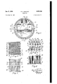
- Fig. l is. a fragmentary transverse section of a steam and water drum in which the invention is employed;
- Fig. 2 is auvertical elevation of one of the separator components involving a plurality of upright separator elements of airfoil section type;
- .Fig, 2. is a horizontal section of the. separator onzthe. line .33 .of Fig. .2;
- Fig. 4 is a partial vertical section on the line 4- l of Fig. 5, showing parts of the separator elements in front elevation;
- Fig. 5 is a horizontal section on the line 5-5 of Fig. 4;
- Fig. 6 is a diagrammatic view illustrating the fluid flow when the separator elements are set with their major transverse axes parallel to the general direction of flow of the fluid stream;
- Fig. '7 is a diagrammatic view similar to Fig. 5, but illustrating the fluid flow when the separator elements are set at the preferred angle of 22 to the general direction of flow of the approaching fluid stream.
- Fig. 1 indicates a steam and water drum It ⁇ of a water tube steam boiler. Steam and water mixtures from steam generat ing tubes are discharged into the drum inlet chambers i2 and is through the circulators I6, I23, and 2c.
- the inlet chambers are provided by the fixed upright walls such as 22 and 2d and their connecting walls such as the end walls and a curved bottom wall 26.
- the water level of the steam generator is indicated at 28, and circulation to the lower parts of the steam generating tubes is provided through downcorners such as 30 communicating with the water space of the drum.
- whirl chamber steam and water separators such as 32 and 34.
- These separators are preferably of the type illustrated in the Rowand and Fletcher Patent 2,289,970 Each has a tangential inlet in communication with the drum inlet chamber so that the centrifugal steam and water separating action may take place therein.
- the separated steam flows through auxiliary separators such as 36 and 38 and then through the separators 40 and 42 which embody the present invention,
- Figs. 2, 3, 4, and 5 of the drawings indicate the structure of the illustrative separator (one of the separators 4! and 42).
- the separator consists of a plurality of rows, R, S, T, and U etc., of spaced upright elements (such as 54, 5B, 58, and 68') of airfoil type sections with their major transverse axes set at an angle of 22 to the general direction of steam flow.
- the steam flow is indicated by the arrow 62 and in Fig. 5 by the line FF and the associated arrow.
- XX indicates the direction of the major transverse axes of the airfoil element 10.
- a row of separator elements of elongated cross-section such as 54 are arranged across a fluid stream path with their major transverse axes in alignment with (or parallel to) the direction of fluid approach, streamline flow takes place across the entire transverse free flow area between the elements, and the bound- 'ary layers do not break away from the stream flowing between adjacent elements.
- Such flow conditions are intended to be indicated in Fig. 6of the drawings.
- a plurality of spaced separator elements of the airfoil type, Ell-I56 are set with their major transverse axes parallel to the general direction of approaching fluid flow as indicated by the arrow I58.
- the fluid approaching the wide leading edges or faces of the separator elements I52 and W3 Bil divides and flows around the leading portions of the elements with the flow generally parallel to those surfaces. Beyond these positions, the flow continues parallel to the sides of the elements with no substantial breaking away from those surfaces.
- the major transverse axes of the elements of the row are positioned at an angle to direction of fluid stream approach or attack, a discontinuity of boundary layers along the one side of the elements develops, and eddy currents of the vortex type are set up.
- the extent to which this zone of discontinuity is projected laterally toward the remaining zone of laminar flow and axially in the general direction of fluid flow is a function of the angular positions of the downstream surfaces of the separator elements.
- the eddy current zone so set up is of a pressure lower than that existing in the adjacent zone of laminar or streamline flow, and it has been found that such low pressure eddy current zones are effective in accumulating moisture particles of such a size that they may separate by gravity even against the upward flow of the approaching stream.
- the fluid flow is divided into a plurality of streams as flow takes place between the elements of each row, and the eddy current zones are successively developed on opposite sides of the interelement laminar flow streams.
- the preferred spacing of the elements is of the order of that shown in the drawings wherein the minimum spacing between successive elements in the same transverse row is approximately equal to the maximum thickness of each element. The entire cross section of the fluid stream flow is thus caused to pass adjacent eddy current zones in which moisture particle agglomeration and separation is effected.
- the elements are positioned with their major transverse axes at a preferred angle of 22 to the approaching direction of the stream.
- the flow resistance through a row of these angularly arranged elements is related to the extent of eddy current zone formation, lesser angles allowing lower pressure drop but with a reduction in extent of the eddy current zone, while greater angles correspondingly increase the fluid pressure drop and the extent of the eddy current zones.
- Angles of 15 to 27 are considered to provide an effective utilization of the described separating action in eddy current zones.
- eddy current or vortex zones will be set up on the downflow lateral surfaces of the airfoil elements while the stream flows past the opposite surfaces in a manner approaching laminar flow, such flow being indicated by the arrow 12 in Fig. '5.
- the eddy current zone along the shadowed side of each airfoil type section, and illustrated at it) in Fig. 5, extends outward from that surface. This is a zone of lower pressure in which the particles carried by the fluid stream accumulate for separation. Some of these particles collect upon the surfaces of the separator elements and they accumulate until they flow down elements asszsaa alon these elements and drainl therefrom at the bottom o'f theseparator.
- separator elements HIP-9'4 are reversely inclined with respect tothe inclination of the first row of elements Mil-422.
- the separation zones effected by the separator elements'of the second row are disposed on their in collaboration-with the element l20,.first forms the eddy current separation zone I29 on its right hand side and then, passing between the separator elements 91 and 92 in the secondrow forms the eddy current zone 9
- tops of the separator elements are held in their operative spaced relationship by one or more members such as I39 shown in Fig. 2.
- trailing edge of a separator element in a leading row is spaced longitudinally of the general direction of fluid flow from the thicker leading edge of immediately following element in the succeeding row to permit the development of eddy current zones of maximum extent.
- fhe airfoil type elements of the preferred construction indicated in Figs. 3 and 5 bear a 3 to 1 relationship of their transverse axes.
- the minor transverse axis for example, is %3 and the major transverse axis is The direction of such major transverse axis is indicated by the line XX of Fig. 5 and the direction of the minor transverse axis is indicated by the line Z-Z. This line is normal to X--X, and disposed at the thickest portion of the element 1!
- the spacin of the elements in each row is preferably In the operation of the separator, water particles impacting against the thicker leading face of a separator element Will separate, some of them passing alhngthe 'side--of" the r'separator to itsed'dy-current "zone” and the-others passing in the laminar :or stream flow along the opposite side of the-*elementand thereafter "passing to an eddy current 'zone'of a following separator element o'f'another transverse row.
Landscapes
- Chemical & Material Sciences (AREA)
- Chemical Kinetics & Catalysis (AREA)
- Separating Particles In Gases By Inertia (AREA)
Description
Dec. 5 50 Filed May 31, 1946 W. H, WAND SEP R Ill HIIIINII ll \IIIMHI 2 Sheet et 1 Il'nn 9 I. llllilllW llllllli IN E R mgm ATTORNEY Dec. 5, 1950 w. H. ROWAND 2,532,332
SEPARATOR Filed May 31, 1946 2 sheets-sheet 2 XNVENTOR PVi/Z H Eon and ATTORNEY Patented Dec. 5, 1950 UNITED STATES PATENT OFFICE SEPARATOR Application May 31, 1946, Scrial'No. 673,290
5 Claims. (01. 183- 75 My invention relates to the separation of material from a fluid stream.
My invention more particularly resides in the effecting of the separation of material of higher density from a fluid stream by creating within that stream, or between divisions of that stream, a separation zone, or zones, of reduced pressure.
More specifically, my invention involves the separation of material from a fluid stream by utilizing the downstream vortex zone produced by the trailing edge of an airfoil type of section when located at a certain angle of attack to the fluid stream. For steam and water separation, I have found that the maximum separation takes place when the angle of attack is 22 By the expression angle of attack, I refer to the angle between the plane of the airfoil and the direction of fluid velocity in the approaching stream. At greater angles, the resistance to flow increases and the separation effectiveness of the zone of reduced pressure decreases. As the angle of attack is decreased from 22 /2, the separation capacity decreases, and the extent of the zone of reduced pressure also decreases.
My invention is particularly adapted for use in connection with the generation of steam, and is effective for the removal of moisture and other impurities from steam discharged from the steam and Water drum of a steam generator.
The importance, in steam generation, of providing clean dry steam has long been recognized, but as the operating pressures and operating capacities of steam generators have increased, it has been realized that the need for removal of moisture and other impurities from the steam to a greater degree, has become more and more important. This is particularly true where the circulating water of a steam generator contains a high concentration of solids for the purpose of preventing internal corrosion of the pressure parts. If particles of such solids are carried by the steam passing from the generator, there would be increased outage and increased maintenance costs by reason of the deposition of the solids in the superheater or on the turbine blades.
Some prior art devices proposed for steam and water separation in a steam boiler drum have been based upon the inertia principle of fluid sep aration, and have involved a series of bafiles arranged to receive the impact of the steam and water mixture entering the drum. Separators of this type have been found ineffective particularly at high boiler loads as the moisture in the mix ture strikingthe separator .bafiles at high. velocity is caused to be so dispersed that a substantial 2 portion of thedivided particles is again plickedup by the stream, and this'u action is repeated in subsequentbafile contacts. Such separators have also involved undesirably high pressure drops.
Other steam and water separators used in boiler steam drums have involved apparatus presenting surfaces closely arranged adjacent streams of fluid, with moisture particles separating from the streams by adhesionito those surfaces.
In contrast, the apparatus embodying my in vention is so arranged that, in normal operation, there are set up eddy currents or vortices in predetermined positions to provide well defined zones of lower pressure in which moisture particles may gather andaccumulate to such Sui-- ficient-mass size that separation bygravity from the flowing vapor may be effected.
Myinvention involves such division and deflection of a steam and water mixture: that a largenumber of lower pressure eddy current zones are distributed throughout the mixture, these zones constantly receiving particles of water. from the flowing mixture. Such particles, collect in these zones, and are subject to constantremoval therefrom, as by gravity. Furthermore, the defiection of the parts of the mixture stream is minimized in order that the separation .of the high gravity particles may be effective with a :minimum flow. resistance.
Another objectof the invention is the. provision of .a separator characterized by the use of a plurality of separator elements of the airfoil type set at such an angle of attack that there is an optimum ratio of total separation in the eddy current zones to pressure drop. A further and more specificobject is the provision of a steam and water drum separator capable of producing clean and dry steam at high boiler loads and varying drum water levels,
The invention will be described with reference to the accompanying drawings, and otherobjects of the invention will appear as the description proceeds.
In the drawings:
Fig. l is. a fragmentary transverse section of a steam and water drum in which the invention is employed;
Fig. 2 .is auvertical elevation of one of the separator components involving a plurality of upright separator elements of airfoil section type;
.Fig, 2. is a horizontal section of the. separator onzthe. line .33 .of Fig. .2;
Fig. 4 is a partial vertical section on the line 4- l of Fig. 5, showing parts of the separator elements in front elevation;
Fig. 5 is a horizontal section on the line 5-5 of Fig. 4;
Fig. 6 is a diagrammatic view illustrating the fluid flow when the separator elements are set with their major transverse axes parallel to the general direction of flow of the fluid stream; and
Fig. '7 is a diagrammatic view similar to Fig. 5, but illustrating the fluid flow when the separator elements are set at the preferred angle of 22 to the general direction of flow of the approaching fluid stream.
In the drawings, Fig. 1 indicates a steam and water drum It} of a water tube steam boiler. Steam and water mixtures from steam generat ing tubes are discharged into the drum inlet chambers i2 and is through the circulators I6, I23, and 2c. The inlet chambers are provided by the fixed upright walls such as 22 and 2d and their connecting walls such as the end walls and a curved bottom wall 26.
The water level of the steam generator is indicated at 28, and circulation to the lower parts of the steam generating tubes is provided through downcorners such as 30 communicating with the water space of the drum.
Secured to the upright walls 22 and 24 are a plurality of whirl chamber steam and water separators such as 32 and 34. These separators are preferably of the type illustrated in the Rowand and Fletcher Patent 2,289,970 Each has a tangential inlet in communication with the drum inlet chamber so that the centrifugal steam and water separating action may take place therein. The separated steam flows through auxiliary separators such as 36 and 38 and then through the separators 40 and 42 which embody the present invention,
From the separators 413, 42, the steam flows through the upright perforated plates 64 and 4t and to a steam oi'ftake 43. Separated water is returned from the pan 50 by a return pipe 52, the outlet of which is disposed below the drum water level as indicated in Fig. 1.
Figs. 2, 3, 4, and 5 of the drawings indicate the structure of the illustrative separator (one of the separators 4!) and 42). The separator consists of a plurality of rows, R, S, T, and U etc., of spaced upright elements (such as 54, 5B, 58, and 68') of airfoil type sections with their major transverse axes set at an angle of 22 to the general direction of steam flow. In Fig. 3, the steam flow is indicated by the arrow 62 and in Fig. 5 by the line FF and the associated arrow. In the latter Figure, XX indicates the direction of the major transverse axes of the airfoil element 10.
Where a row of separator elements of elongated cross-section such as 54 are arranged across a fluid stream path with their major transverse axes in alignment with (or parallel to) the direction of fluid approach, streamline flow takes place across the entire transverse free flow area between the elements, and the bound- 'ary layers do not break away from the stream flowing between adjacent elements. Such flow conditions are intended to be indicated in Fig. 6of the drawings. Here, a plurality of spaced separator elements of the airfoil type, Ell-I56 are set with their major transverse axes parallel to the general direction of approaching fluid flow as indicated by the arrow I58. It will be noted that the fluid approaching the wide leading edges or faces of the separator elements I52 and W3 Bil divides and flows around the leading portions of the elements with the flow generally parallel to those surfaces. Beyond these positions, the flow continues parallel to the sides of the elements with no substantial breaking away from those surfaces. However, when the major transverse axes of the elements of the row are positioned at an angle to direction of fluid stream approach or attack, a discontinuity of boundary layers along the one side of the elements develops, and eddy currents of the vortex type are set up. The extent to which this zone of discontinuity is projected laterally toward the remaining zone of laminar flow and axially in the general direction of fluid flow is a function of the angular positions of the downstream surfaces of the separator elements.
The eddy current zone so set up is of a pressure lower than that existing in the adjacent zone of laminar or streamline flow, and it has been found that such low pressure eddy current zones are effective in accumulating moisture particles of such a size that they may separate by gravity even against the upward flow of the approaching stream.
By relatively close spacing of the elements of each row and by inclining the major transverse axes of the elements of alternate rows in opposite directions, the fluid flow is divided into a plurality of streams as flow takes place between the elements of each row, and the eddy current zones are successively developed on opposite sides of the interelement laminar flow streams. The preferred spacing of the elements is of the order of that shown in the drawings wherein the minimum spacing between successive elements in the same transverse row is approximately equal to the maximum thickness of each element. The entire cross section of the fluid stream flow is thus caused to pass adjacent eddy current zones in which moisture particle agglomeration and separation is effected.
In a preferred embodiment of apparatus for carrying out the above described method of particle separation the elements are positioned with their major transverse axes at a preferred angle of 22 to the approaching direction of the stream. The flow resistance through a row of these angularly arranged elements is related to the extent of eddy current zone formation, lesser angles allowing lower pressure drop but with a reduction in extent of the eddy current zone, while greater angles correspondingly increase the fluid pressure drop and the extent of the eddy current zones. Angles of 15 to 27 are considered to provide an effective utilization of the described separating action in eddy current zones.
With the airfoil elements arranged as shown, and at such an angle as 22 (the angle A formed by the lines ET and IQ; in Fig. 5) eddy current or vortex zones will be set up on the downflow lateral surfaces of the airfoil elements while the stream flows past the opposite surfaces in a manner approaching laminar flow, such flow being indicated by the arrow 12 in Fig. '5. The eddy current zone along the shadowed side of each airfoil type section, and illustrated at it) in Fig. 5, extends outward from that surface. This is a zone of lower pressure in which the particles carried by the fluid stream accumulate for separation. Some of these particles collect upon the surfaces of the separator elements and they accumulate until they flow down elements asszsaa alon these elements and drainl therefrom at the bottom o'f theseparator.
The separate elements l |8-l 2| -=(Fig."7) are set at such an angle to the general direction of approaching fluid flow, =I'H, that eddy current zones such as W2 1 1.2w, and 1 19 are set :up adjacent "the shadowed; or downstreamfaces of the H9, [20,121, respectively. These zones may extend beyond thetrailing edges of these elements as indicated in 'the drawing. The
separator elements HIP-9'4 are reversely inclined with respect tothe inclination of the first row of elements Mil-422. With this arrangement, the separation zones effected by the separator elements'of the second row, are disposed on their in collaboration-with the element l20,.first forms the eddy current separation zone I29 on its right hand side and then, passing between the separator elements 91 and 92 in the secondrow forms the eddy current zone 9| disposed on its opposite side. When this-actionis repeated'severa-l times, as when the fluid passes through a large number of rows of separator elements (as indicated in Fig. 3), the above indicated stream of fluid is subjected to recurrent separating effects alternating on opposite sides thereon. "The total effect being the substantially complete separation of any entrained material of higher density in the stream.
Free drainage of the separated water from the lower ends of the separator elements is permitted by reason of the construction indicated in Figs. 3, 4, and 5. The lower ends of the elements are supported by spaced bottom members Bil-88, the rows of separator elements bein disposed ahove the spaces between the bottom members. In Fig. 5, for example, upright airfoil type elements 9994 are mainly disposed above the free space between the bottom members 83 and 84 where the corresponding edges I00, IOI, I 02,
and H13 of these members are welded to the bottom member 83 and their opposite edges lid-454 are welded to an edge of the bottom member 84. Similarly, the members 10, I20, I 2|, and H22 are welded to the edges of the bottom members 84 and 85, respectively.
The tops of the separator elements are held in their operative spaced relationship by one or more members such as I39 shown in Fig. 2.
In this arrangement the trailing edge of a separator element in a leading row is spaced longitudinally of the general direction of fluid flow from the thicker leading edge of immediately following element in the succeeding row to permit the development of eddy current zones of maximum extent.
fhe airfoil type elements of the preferred construction indicated in Figs. 3 and 5 bear a 3 to 1 relationship of their transverse axes. The minor transverse axis, for example, is %3 and the major transverse axis is The direction of such major transverse axis is indicated by the line XX of Fig. 5 and the direction of the minor transverse axis is indicated by the line Z-Z. This line is normal to X--X, and disposed at the thickest portion of the element 1! The spacin of the elements in each row is preferably In the operation of the separator, water particles impacting against the thicker leading face of a separator element Will separate, some of them passing alhngthe 'side--of" the r'separator to itsed'dy-current "zone" and the-others passing in the laminar :or stream flow along the opposite side of the-*elementand thereafter "passing to an eddy current 'zone'of a following separator element o'f'another transverse row.
What 'is cl'aimed isi 1. In afluid separator, groupsof spaced and parallel a-irfoil type separator elements arranged inspaced rows disposedeuccessivelyacross a high velocity fluid stream, each such element being of tapered cross-section with agreater than 2-1 ratio of'its major "transverse dimension to its minor transverse dimension and with its thickest portion near its leading edge and combining therewith"topresentlaminar flow curved sur faces confronting the oncoming fluid stream, means for supporting the elements with the direction of their "major transverse dimensions at 'an ang le'within the 15 to 27 range to the general direction of how of said fluid stream, the said angular disposition of said elements and said curvature of their leading edge portions causing the fluid stream to have substantially laminar flow divisions between successive elements and eddy-current fluid separation zones of lower pressure alon-g'the downstream faces o'f'the elements and latera'ilyof saidlaniinar flow divisicns, said supporting means also holding the separator elements of any "succeeding row angled as above but reverselyto the separator elements of the immediately preceding row, and means providing for the removal of the heavier fluid particles which are formed in the eddy current zones and gravity separated therefrom.
2. In a gas and liquid separator, successive spaced rows of transversely spaced elements of airfoil type cross section extending across a high velocity fluid stream, said elements having their major transverse axes disposed at an angle of from 15 to 27 to the general direction of flow of the approaching fluid stream, at least the maior portions of the downstream faces of each of said elements being disposed at an angle to said general direction of the approaching stream greater than the angle made by said major transverse axes with said general direction, this construction and arrangement setting up on the downflow sides of said elements eddy current zones of lower pressures in which the said particles are separated from the fluid, said airfoil'elements in each row being of tapering section with their portions of maximum thickness near their edge portions confronting the oncoming fluid stream.
3. In a gas and liquid separator, successive spaced rows of transversely spaced elements of airfoil type cross section extending across a high velocity fluid stream, said elements having their major transverse axes disposed at an angle of from 15 to 27 to the general direction of flow of the approaching fluid stream with the elements of successive rows reversely oblique to said general direction of flow, at least the major portions of the downstream faces of each of said elements being disposed at an angle to said general direction of the approaching stream greater than the angle made by said major transverse axes with said general direction, this construction and arrangement setting up on the downflow sides of said elements eddy current zones of lower pres sures in which the said particles are separated from the fluid, said airfoil elements in each row being of tapering section with their portions of maximum thickness near their edge portions confronting the oncoming fluid stream.
- 4. In a gas and liquid separator successive spaced rows of transversely spaced elements of airfoil type cross section extending across a high velocity fluid stream, said elements having their major transverse axes disposed at an angle of from 15 to 27 to the general direction of flow of the approaching fluid stream, at least the major portions of the downstream faces of each of said elements being disposed at an angle to said general direction of the approaching stream greater than the angle made by said major transverse axes with said general direction, this construction and arrangement setting up on the downflow sides of said elements eddy current zones of lower pressures in which the said particles are separated from the fluid, said airfoil elements in each row being of tapering section with their portions of maximum thickness near their edge portions confronting the oncoming fluid stream, the ratio of the major transverse dimension of each separating element to its minor transverse dimension being greater than two to one.
5. In a gas and liquid separator, successive spaced rows of transversely spaced elements of airfoil type cross section extending across a high velocity fluid stream, the minimum transverse spacing of successive elements in each row being approximately equal to the maximum thickness of each element, said elements having their major transverse axes disposed at an angle of from 15 to 27 to the general direction of flow of the approaching fluid stream, at least the major portions of the downstream faces of each of said elements being disposed at an angle to saidgeneral direction of the approaching stream greater than the angle made by said major transverse axes with said general direction, this construction and arrangement setting up on the downflow sides of said elements eddy current zones of lower pressures in which the said particles are separated from the fluid, said airfoil ele-' ments in each row being of tapering section with their portions of maximum thickness near their edge portions confronting the oncoming fluid stream.-
WILL H. ROWAND.
REFERENCES CITED The following references are'of record in the file of this patent:
UNITED STATES PATENTS
Priority Applications (1)
| Application Number | Priority Date | Filing Date | Title |
|---|---|---|---|
| US673290A US2532332A (en) | 1946-05-31 | 1946-05-31 | Separator |
Applications Claiming Priority (1)
| Application Number | Priority Date | Filing Date | Title |
|---|---|---|---|
| US673290A US2532332A (en) | 1946-05-31 | 1946-05-31 | Separator |
Publications (1)
| Publication Number | Publication Date |
|---|---|
| US2532332A true US2532332A (en) | 1950-12-05 |
Family
ID=24702043
Family Applications (1)
| Application Number | Title | Priority Date | Filing Date |
|---|---|---|---|
| US673290A Expired - Lifetime US2532332A (en) | 1946-05-31 | 1946-05-31 | Separator |
Country Status (1)
| Country | Link |
|---|---|
| US (1) | US2532332A (en) |
Cited By (14)
| Publication number | Priority date | Publication date | Assignee | Title |
|---|---|---|---|---|
| US2739663A (en) * | 1952-08-12 | 1956-03-27 | Gurney William Brewster | High pressure steam purifier |
| US2838132A (en) * | 1955-12-09 | 1958-06-10 | Bristol Aero Engines Ltd | Means for removing moisture from a gas |
| US2859831A (en) * | 1956-01-09 | 1958-11-11 | Fluor Corp | Cooling tower mist eliminator |
| US3360911A (en) * | 1963-12-23 | 1968-01-02 | Bixby Zimmer Engineering Compa | Filter |
| US4483696A (en) * | 1982-09-07 | 1984-11-20 | Foster Wheeler Energy Corporation | Steam separating apparatus and separators used therein |
| US4530707A (en) * | 1978-11-22 | 1985-07-23 | Ovard John C | Apparatus for removing droplets entrained in a gas stream |
| US4565554A (en) * | 1982-09-07 | 1986-01-21 | Foster Wheeler Energy Corporation | Steam separating apparatus and separators used therein |
| US5033915A (en) * | 1989-10-27 | 1991-07-23 | The Babcock & Wilcox Company | Low pressure drop steam/water conical cyclone separator |
| US5271753A (en) * | 1992-12-29 | 1993-12-21 | Combustion Engineering, Inc. | Steam drying apparatus |
| US6051041A (en) * | 1995-02-06 | 2000-04-18 | Munters Euroform Gmbh | Separation apparatus |
| US20080069646A1 (en) * | 2006-09-20 | 2008-03-20 | Melvin John Albrecht | Extended water level range steam/water conical cyclone separator |
| US20090010721A1 (en) * | 2007-07-05 | 2009-01-08 | Albrecht Melvin J | Steam/water conical cyclone separator |
| US20090173700A1 (en) * | 2006-05-05 | 2009-07-09 | Wayne State University | Device and method of separating and concentrating microfluidic particles |
| US10272376B2 (en) * | 2014-06-18 | 2019-04-30 | Alupro Oy | Louvered separator |
Citations (5)
| Publication number | Priority date | Publication date | Assignee | Title |
|---|---|---|---|---|
| US1156511A (en) * | 1913-11-28 | 1915-10-12 | Gen Electric | Cooling-liquid economizer. |
| US1789931A (en) * | 1926-10-15 | 1931-01-20 | American Air Filter Co | Air filter |
| US1886927A (en) * | 1927-09-09 | 1932-11-08 | Charles W Williams | Air filter |
| US2007966A (en) * | 1933-02-28 | 1935-07-16 | Babcock & Wilcox Co | Steam separator |
| GB433943A (en) * | 1933-12-16 | 1935-08-16 | Hall & Kay Ltd | Improvements in or relating to filters or the like for removing suspended matters from air or other gases |
-
1946
- 1946-05-31 US US673290A patent/US2532332A/en not_active Expired - Lifetime
Patent Citations (5)
| Publication number | Priority date | Publication date | Assignee | Title |
|---|---|---|---|---|
| US1156511A (en) * | 1913-11-28 | 1915-10-12 | Gen Electric | Cooling-liquid economizer. |
| US1789931A (en) * | 1926-10-15 | 1931-01-20 | American Air Filter Co | Air filter |
| US1886927A (en) * | 1927-09-09 | 1932-11-08 | Charles W Williams | Air filter |
| US2007966A (en) * | 1933-02-28 | 1935-07-16 | Babcock & Wilcox Co | Steam separator |
| GB433943A (en) * | 1933-12-16 | 1935-08-16 | Hall & Kay Ltd | Improvements in or relating to filters or the like for removing suspended matters from air or other gases |
Cited By (18)
| Publication number | Priority date | Publication date | Assignee | Title |
|---|---|---|---|---|
| US2739663A (en) * | 1952-08-12 | 1956-03-27 | Gurney William Brewster | High pressure steam purifier |
| US2838132A (en) * | 1955-12-09 | 1958-06-10 | Bristol Aero Engines Ltd | Means for removing moisture from a gas |
| US2859831A (en) * | 1956-01-09 | 1958-11-11 | Fluor Corp | Cooling tower mist eliminator |
| US3360911A (en) * | 1963-12-23 | 1968-01-02 | Bixby Zimmer Engineering Compa | Filter |
| US4530707A (en) * | 1978-11-22 | 1985-07-23 | Ovard John C | Apparatus for removing droplets entrained in a gas stream |
| US4483696A (en) * | 1982-09-07 | 1984-11-20 | Foster Wheeler Energy Corporation | Steam separating apparatus and separators used therein |
| US4565554A (en) * | 1982-09-07 | 1986-01-21 | Foster Wheeler Energy Corporation | Steam separating apparatus and separators used therein |
| US5033915A (en) * | 1989-10-27 | 1991-07-23 | The Babcock & Wilcox Company | Low pressure drop steam/water conical cyclone separator |
| US5271753A (en) * | 1992-12-29 | 1993-12-21 | Combustion Engineering, Inc. | Steam drying apparatus |
| US6051041A (en) * | 1995-02-06 | 2000-04-18 | Munters Euroform Gmbh | Separation apparatus |
| US20090173700A1 (en) * | 2006-05-05 | 2009-07-09 | Wayne State University | Device and method of separating and concentrating microfluidic particles |
| US7837944B2 (en) * | 2006-05-05 | 2010-11-23 | Wayne State University | Device for separating and concentrating microfluidic particles |
| US20080069646A1 (en) * | 2006-09-20 | 2008-03-20 | Melvin John Albrecht | Extended water level range steam/water conical cyclone separator |
| US7842113B2 (en) | 2006-09-20 | 2010-11-30 | Babcock & Wilcox Power Generation Group, Inc. | Extended water level range steam/water conical cyclone separator |
| US20090010721A1 (en) * | 2007-07-05 | 2009-01-08 | Albrecht Melvin J | Steam/water conical cyclone separator |
| EP2136137A2 (en) | 2007-07-05 | 2009-12-23 | The Babcock & Wilcox Company | Steam/water conical cyclone separator |
| US7637699B2 (en) | 2007-07-05 | 2009-12-29 | Babcock & Wilcox Power Generation Group, Inc. | Steam/water conical cyclone separator |
| US10272376B2 (en) * | 2014-06-18 | 2019-04-30 | Alupro Oy | Louvered separator |
Similar Documents
| Publication | Publication Date | Title |
|---|---|---|
| US2532332A (en) | Separator | |
| US2182862A (en) | Separating method and apparatus | |
| US4537608A (en) | System for removing contaminant particles from a gas | |
| US3216182A (en) | Axial flow vapor-liquid separator | |
| US1818994A (en) | Dust collector | |
| US3338035A (en) | Parallel plate deflection type separator | |
| US4390426A (en) | Centrifugal separators of the cyclone type | |
| US2506273A (en) | Particle separator | |
| BRPI0803051B1 (en) | gas-solid suspension cyclonic separator and separation method | |
| GB1155484A (en) | Centrifugal Type Gas Cleaners | |
| US5584901A (en) | Dispersed phase separator | |
| US3329130A (en) | Pressure recovery axial flow vapor-liquid separator | |
| US2926749A (en) | Separator-electrodesystem for electrofilters | |
| US3472209A (en) | Apparatus for separating water from wet steam prior to superheating of the steam | |
| US3240001A (en) | Device for the separation of moisture drops from a gas-stream | |
| US1708653A (en) | A cobpoba | |
| US3019856A (en) | Dust collector | |
| US3320729A (en) | Apparatus for removing liquid from a liquid laden gas stream | |
| US3500796A (en) | Apparatus for separating water from wet steam prior to superheating of the steam | |
| US2058240A (en) | Gas and liquid separating apparatus | |
| US3881900A (en) | Gas liquid separator | |
| CN109395476A (en) | A kind of steam-water separator with pressure recovery grade | |
| US2422527A (en) | Gas separator | |
| US2993565A (en) | Liquid and gas separating apparatus | |
| US2708486A (en) | Gas cleaning apparatus |