US20030158740A1 - Inverse-modified discrete cosine transform and overlap-add method and hardware structure for MPEG layer3 audio signal decoding - Google Patents
Inverse-modified discrete cosine transform and overlap-add method and hardware structure for MPEG layer3 audio signal decoding Download PDFInfo
- Publication number
- US20030158740A1 US20030158740A1 US10/078,021 US7802102A US2003158740A1 US 20030158740 A1 US20030158740 A1 US 20030158740A1 US 7802102 A US7802102 A US 7802102A US 2003158740 A1 US2003158740 A1 US 2003158740A1
- Authority
- US
- United States
- Prior art keywords
- discrete cosine
- cosine transform
- inverse
- modified discrete
- hardware structure
- Prior art date
- Legal status (The legal status is an assumption and is not a legal conclusion. Google has not performed a legal analysis and makes no representation as to the accuracy of the status listed.)
- Granted
Links
- 238000000034 method Methods 0.000 title claims abstract description 58
- 230000005236 sound signal Effects 0.000 title claims abstract description 28
- 230000006835 compression Effects 0.000 claims description 18
- 238000007906 compression Methods 0.000 claims description 18
- 230000015572 biosynthetic process Effects 0.000 claims description 14
- 238000003786 synthesis reaction Methods 0.000 claims description 14
- 238000013461 design Methods 0.000 claims description 7
- 230000002860 competitive effect Effects 0.000 abstract 1
- 238000010586 diagram Methods 0.000 description 5
- 230000000694 effects Effects 0.000 description 3
- 230000005540 biological transmission Effects 0.000 description 2
- 238000013139 quantization Methods 0.000 description 2
- 238000004364 calculation method Methods 0.000 description 1
- 238000009432 framing Methods 0.000 description 1
- 230000006870 function Effects 0.000 description 1
- 230000036039 immunity Effects 0.000 description 1
- 230000010354 integration Effects 0.000 description 1
- 238000012986 modification Methods 0.000 description 1
- 230000004048 modification Effects 0.000 description 1
- 238000012545 processing Methods 0.000 description 1
- 238000011160 research Methods 0.000 description 1
- 230000035945 sensitivity Effects 0.000 description 1
- 238000001228 spectrum Methods 0.000 description 1
Images


Classifications
-
- G—PHYSICS
- G10—MUSICAL INSTRUMENTS; ACOUSTICS
- G10L—SPEECH ANALYSIS TECHNIQUES OR SPEECH SYNTHESIS; SPEECH RECOGNITION; SPEECH OR VOICE PROCESSING TECHNIQUES; SPEECH OR AUDIO CODING OR DECODING
- G10L19/00—Speech or audio signals analysis-synthesis techniques for redundancy reduction, e.g. in vocoders; Coding or decoding of speech or audio signals, using source filter models or psychoacoustic analysis
- G10L19/04—Speech or audio signals analysis-synthesis techniques for redundancy reduction, e.g. in vocoders; Coding or decoding of speech or audio signals, using source filter models or psychoacoustic analysis using predictive techniques
- G10L19/16—Vocoder architecture
-
- G—PHYSICS
- G10—MUSICAL INSTRUMENTS; ACOUSTICS
- G10L—SPEECH ANALYSIS TECHNIQUES OR SPEECH SYNTHESIS; SPEECH RECOGNITION; SPEECH OR VOICE PROCESSING TECHNIQUES; SPEECH OR AUDIO CODING OR DECODING
- G10L19/00—Speech or audio signals analysis-synthesis techniques for redundancy reduction, e.g. in vocoders; Coding or decoding of speech or audio signals, using source filter models or psychoacoustic analysis
- G10L19/02—Speech or audio signals analysis-synthesis techniques for redundancy reduction, e.g. in vocoders; Coding or decoding of speech or audio signals, using source filter models or psychoacoustic analysis using spectral analysis, e.g. transform vocoders or subband vocoders
- G10L19/0212—Speech or audio signals analysis-synthesis techniques for redundancy reduction, e.g. in vocoders; Coding or decoding of speech or audio signals, using source filter models or psychoacoustic analysis using spectral analysis, e.g. transform vocoders or subband vocoders using orthogonal transformation
Definitions
- the present invention generally relates to a method and hardware structure for audio signal decoding, and more particularly, to an inverse-modified discrete cosine transform and overlap-add method and hardware structure for MPEG Layer3 audio signal decoding.
- MPEG is further divided into Layer1, Layer2 and Layer3.
- Layer1 the higher the level of the layer, the more complicated the compression method, the distortion of the corresponding recovered audio signal is much less, and the effect is better.
- the encoding process of MPEG can be divided into the encoder and the decoder portions.
- the audio data is processed and converted into 32 data sub-bands by using the analysis sub-band filter bank.
- the data belonging to different bands can be assigned to different bits according to the psycho-acoustical model that simulates the artificial ear acoustic effect.
- the objective of the compression can be achieved via quantization.
- the data is sent out in a specific data format framing.
- the decoder portion looks like the reverse operation of the encoder.
- the data is unpacked first, and after the inverse quantization process, the 32 data sub-bands are integrated into the original audio data by using the synthesis sub-band filter bank.
- Multi-channel audio encoding is further provided, while all the other aspects are basically the same as the MPEG I.
- Multi-channel audio can be divided into the Left (L) and Right (R) channel audio transmitted via the basic transmission channels T 0 , T 1 , and the Central (C), Left Surround (LS) and Right Surround (RS) channel audio transmitted via the extended transmission channels T 2 , T 3 , T 4 .
- the multichannel decoder is needed for the MPEG-II audio decoding to reconstruct the multichannel audio signal.
- MP3 MPEG Layer3
- IMDCT inverse-modified discrete cosine transform
- the present invention provides an inverse-modified discrete cosine transform and overlap-add method and hardware structure for MPEG Layer3 audio signal decoding.
- the present invention implements the entire hardware structure via the high speed algorithm of the inverse-modified discrete cosine transform and overlap-add, so that the entire system is able to fulfill the low cost and high performance requirements.
- the present invention provides an inverse-modified discrete cosine transform and overlap-add method for MPEG Layer3 audio signal decoding.
- X(k) is the sub-band sample and Z(i) is the sub-band sample after process.
- window type is 0, 1, 3, n equals 36; whereas when window type is 2, n equals 12.
- the dynamic window inverse-modified discrete cosine transform module is provided.
- the operation of the inverse-modified discrete cosine transform is processed by the multiplier-adder of the dynamic window inverse-modified discrete cosine transform module.
- the result after the operation of the inverse-modified discrete cosine transform is stored in the register stack of the dynamic window inverse-modified discrete cosine transform module.
- the operation of the overlap-add is processed by the multiplier-adder, and the result after the operation of the overlap-add is stored in the buffer memory of the dynamic window inverse-modified discrete cosine transform module.
- the present invention further provides an inverse-modified discrete cosine transform and overlap-add hardware structure for MPEG Layer3 audio signal decoding.
- the hardware structure comprises the dynamic window inverse-modified discrete cosine transform module and the dynamic window inverse-modified discrete cosine transform buffer memory.
- the dynamic window inverse-modified discrete cosine transform module comprises the multiplier-adder and the register stack.
- the multiplier-adder is used to calculate the inverse-modified discrete cosine transform and overlap-add
- the register stack is coupled to the multiplier-adder and is used to store the operation result of the inverse-modified discrete cosine transform.
- the dynamic window inverse-modified discrete cosine transform buffer memory is coupled to the dynamic window inverse-modified discrete cosine transform module and is used to store the operation result of the overlap-add.
- the present invention implements the entire hardware structure by using the fast algorithm of the dynamic window inverse-modified discrete cosine transform and overlap-add, and makes the entire system fulfill the lost cost and high performance requirements.
- FIG. 1 schematically shows the decoding flow chart of the MP3 of the inverse-modified discrete cosine transform and overlap-add method and hardware structure for MPEG Layer3 audio signal decoding according to the present invention
- FIG. 2 schematically shows the flow chart of the inverse-modified discrete cosine transform and overlap-add method for MPEG Layer3 audio signal decoding of a preferred embodiment according to the present invention
- FIG. 3 schematically shows the hardware structure diagram of the inverse-modified discrete cosine transform and overlap-add hardware structure for MPEG Layer3 audio signal decoding of a preferred embodiment according to the present invention
- FIG. 4 schematically shows the layout diagram of the DWIMDCT buffer memory of FIG. 3.
- FIG. 5 schematically shows the sketch map of the sequence of writing of the memory bank in the DWIMDCT buffer memory and the sequence of reading of the synthesis filter bank.
- the present invention is suitable for the MPEG Layer3,but no matter whether MPEG-I or MPEG-II, the audio signal can all be decoded.
- MP3 is the most complicated algorithm, and also provides highest compression rate. Therefore, the preferred embodiment provided by the present invention is aimed at the entire MP3 compression algorithm, so as to reduce the quantity of the data and operation.
- the fast algorithm is provided accordingly. Then, the entire hardware structure is implemented by using the fast algorithm, so that the entire system fulfills the low cost and high performance requirements.
- FIG. 1 schematically shows the decoding flow chart of the MP3 of the inverse-modified discrete cosine transform and overlap-add method and hardware structure for MPEG Layer3 audio signal decoding according to the present invention.
- the whole flow can be divided into the pre-process portion 10 and the post-process portion 12 .
- the pre-process portion 10 first obtains the bit stream and finds out the head 10 (step s 1 02 ). It then decodes the remark information (step s 104 ), decodes the proportion factor (step s 106 ), and decodes the Huffman data (step s 108 ).
- the pre-process portion 10 is mostly used for the process of the bit stream. In general, the operation quantity for this portion is not so large. However, the process is very fussy, and thus this portion generally can be implemented by using the finite state machine and the embedded micro-controller, so that the entire system design can be effectively simplified. There has been a lot of research aimed at this portion in recent years.
- the post-process portion 12 mostly comprises the synthesis process of the inverse-modified discrete cosine transform (abbreviated as IMDCT) and the overlap-add of the present invention (these two processes cooperate and are called the dynamic window inverse-modified discrete cosine transform (abbreviated as DWIMDCT)) (step s 116 ) and also the process of the synthesis filterbank (step s 118 ).
- the pulse code modulation sample is output (step s 120 ).
- the quantity of the operation of the post-process 12 is larger than the pre-process 10 , and takes about 80% of the whole process. Because of this, the post-process 12 needs to be implemented by an appropriate hardware structure, so that the entire system can fulfill the low cost and high performance requirements.
- the present invention provides a flow chart of a preferred embodiment using the inverse-modified discrete cosine transform and overlap-add method for MPEG Layer3 audio signal decoding (that is the IMDCT fast algorithm), as shown in FIG. 2.
- the 32 sub-band samples of the compressed audio signal are applied with the operation of the inverse-modified discrete cosine transform and overlap-add by the IMDCT fast algorithm according to equation (1),
- FIG. 3 schematically shows the hardware structure diagram of the inverse-modified discrete cosine transform and overlap-add hardware structure for MPEG Layer3 audio signal decoding of a preferred embodiment according to the present invention.
- the hardware structure comprises the DWIMDCT module 30 and the DWIMDCT buffer memory 32 .
- the DWIMDCT module 30 mostly comprises the multiplier-adder (MACO) 302 and the register stack 304 .
- the operation method of the hardware structure is described hereafter.
- the multiplier-adder 302 is utilized by the inverse-modified discrete cosine transform for calculation, and the final result is subsequently stored in the register stack 304 .
- the register stack 304 comprises 18 registers.
- the overlap-add of the dynamic window is the follow-on operation.
- the operation of the overlap-add of the dynamic window is also accomplished by using the multiplier-adder 302 , and the final result is stored in the DWIMDCT buffer memory 32 .
- FIG. 4 schematically shows the layout diagram of the DWIMDCT buffer memory 32 .
- the DWIMDCT buffer memory 32 comprises 3 memory banks (memory bank 0, memory bank 1 and memory bank 2 ), each memory bank can be further divided into 32 sub-band blocks, and each sub-band block is able to store 18 sample data. Furthermore, the hardware structure and the synthesis filter bank of the present invention are able to form a two-stage high performance pipeline process. The sequence of the DWIMDCT writing of the sample data contained in each memory bank of the DWIMDCT buffer memory 32 and the sequence of the reading of the synthesis filter bank are shown in FIG. 5.
- the hardware structure of the inverse-modified discrete cosine transform and overlap-add for MPEG Layer3 audio signal decoding according to the present invention is easily compatible with the hardware of other modules, and is suitable for the design of the very large scale integration (VLSI). If the synthesis filter bank module can be integrated, the hardware utilization will be significantly enhanced, as will the operation performance of the entire decoder. Therefore, the MPEG Layer3 can be implemented by the ASIC, so that the entire system can fulfill the low cost and high performance requirements.
- VLSI very large scale integration
- the present invention provides a low cost fast algorithm of the inverse-modified discrete cosine transform and overlap-add.
- the present invention provides a hardware structure that is suitable for the inverse-modified discrete cosine transform and overlap-add in the MPEG Layer3 decoder.
- the hardware structure of the present invention makes the MPEG Layer3 able to be implemented by the ASIC, so that the entire system fulfills the low cost and high performance requirements.
Landscapes
- Engineering & Computer Science (AREA)
- Physics & Mathematics (AREA)
- Computational Linguistics (AREA)
- Signal Processing (AREA)
- Health & Medical Sciences (AREA)
- Audiology, Speech & Language Pathology (AREA)
- Human Computer Interaction (AREA)
- Acoustics & Sound (AREA)
- Multimedia (AREA)
- Spectroscopy & Molecular Physics (AREA)
- Compression, Expansion, Code Conversion, And Decoders (AREA)
Abstract
Description
- 1. Field of Invention
- The present invention generally relates to a method and hardware structure for audio signal decoding, and more particularly, to an inverse-modified discrete cosine transform and overlap-add method and hardware structure for MPEG Layer3 audio signal decoding.
- 2. Description of Related Art
- Digital audio signal processing is widely used. This is because the digital audio signal immunity to noise is higher than the analog signal. However, since it is quite often demanded to process a large amount of data within a very short time and still needs to maintain the effect of high audio quality, a lot of the audio signal compression standards have been developed. The motion picture experts group (abbreviated as MPEG) standard is widely accepted due to its high compression rate and low distortion. MPEG, using the different sensitivity of the human ear to different frequency bands, assigns fewer bits to the audio to which the human ear is not so sensitive, to achieve the objective of compression.
- Furthermore, in order to accommodate different levels of audio quality with the compression method, MPEG is further divided into Layer1, Layer2 and Layer3. Generally speaking, the higher the level of the layer, the more complicated the compression method, the distortion of the corresponding recovered audio signal is much less, and the effect is better.
- The encoding process of MPEG can be divided into the encoder and the decoder portions. In the encoder portion, the audio data is processed and converted into 32 data sub-bands by using the analysis sub-band filter bank. Then, the data belonging to different bands can be assigned to different bits according to the psycho-acoustical model that simulates the artificial ear acoustic effect. Afterwards, the objective of the compression can be achieved via quantization. Finally, the data is sent out in a specific data format framing.
- The decoder portion looks like the reverse operation of the encoder. The data is unpacked first, and after the inverse quantization process, the 32 data sub-bands are integrated into the original audio data by using the synthesis sub-band filter bank.
- As to the MPEG-II audio encoding standard, multi-channel audio encoding is further provided, while all the other aspects are basically the same as the MPEG I. Multi-channel audio can be divided into the Left (L) and Right (R) channel audio transmitted via the basic transmission channels T 0, T1, and the Central (C), Left Surround (LS) and Right Surround (RS) channel audio transmitted via the extended transmission channels T2, T3, T4. The multichannel decoder is needed for the MPEG-II audio decoding to reconstruct the multichannel audio signal.
- The MPEG LAYER3 compression standard, using the MPEG Layer3 (MP3) compression algorithm, is widely used in the application of digital broadcast and multimedia. As to the digital audio signal compression, MP3 is the most complicated algorithm, providing the highest compression rate within MPEG. MP3 utilizes the inverse-modified discrete cosine transform (hereinafter abbreviated as IMDCT) and the sub-band coding techniques, whereby MP3 can achieve such high compression rate.
- The hardware structure of MPEG Layer1and Layer2 decoders has already been physically implemented by many researchers. However, there is no appropriate hardware structure to implement MP3. Most of the hardware structure design nowadays is implemented using the general digital signal processor (abbreviated as DSP). This design 5 utilizes program control to achieve the objective. However, a large amount of memory is needed for this design to store the program code, and thus the hardware burden and area is increased, so that the performance of the entire system cannot achieve the optimum.
- The present invention provides an inverse-modified discrete cosine transform and overlap-add method and hardware structure for MPEG Layer3 audio signal decoding. The present invention implements the entire hardware structure via the high speed algorithm of the inverse-modified discrete cosine transform and overlap-add, so that the entire system is able to fulfill the low cost and high performance requirements.
- In order to at least achieve the objective mentioned above and other objectives, the present invention provides an inverse-modified discrete cosine transform and overlap-add method for MPEG Layer3 audio signal decoding. At first, the 32 sub-band samples of the compressed audio signal are applied with the operation of the inverse-modified discrete cosine transform and overlap-add according to equation (1), inverse-modified discrete cosine transform:

- overlap-add:
- Z(i)=x(i)*win(i,p)
-

-

- where X(k) is the sub-band sample and Z(i) is the sub-band sample after process. When window type is 0, 1, 3, n equals 36; whereas when window type is 2, n equals 12. Then, the dynamic window inverse-modified discrete cosine transform module is provided. The operation of the inverse-modified discrete cosine transform is processed by the multiplier-adder of the dynamic window inverse-modified discrete cosine transform module. The result after the operation of the inverse-modified discrete cosine transform is stored in the register stack of the dynamic window inverse-modified discrete cosine transform module. Afterwards, the operation of the overlap-add is processed by the multiplier-adder, and the result after the operation of the overlap-add is stored in the buffer memory of the dynamic window inverse-modified discrete cosine transform module.
- The present invention further provides an inverse-modified discrete cosine transform and overlap-add hardware structure for MPEG Layer3 audio signal decoding. The hardware structure comprises the dynamic window inverse-modified discrete cosine transform module and the dynamic window inverse-modified discrete cosine transform buffer memory. The dynamic window inverse-modified discrete cosine transform module comprises the multiplier-adder and the register stack. The multiplier-adder is used to calculate the inverse-modified discrete cosine transform and overlap-add, the register stack is coupled to the multiplier-adder and is used to store the operation result of the inverse-modified discrete cosine transform. The dynamic window inverse-modified discrete cosine transform buffer memory is coupled to the dynamic window inverse-modified discrete cosine transform module and is used to store the operation result of the overlap-add.
- In summary, the present invention implements the entire hardware structure by using the fast algorithm of the dynamic window inverse-modified discrete cosine transform and overlap-add, and makes the entire system fulfill the lost cost and high performance requirements.
- The accompanying drawings are included to provide a further understanding of the invention, and are incorporated in and constitute a part of this specification. The drawings illustrate embodiments of the invention, and together with the description, serve to explain the principles of the invention. In the drawings,
- FIG. 1 schematically shows the decoding flow chart of the MP3 of the inverse-modified discrete cosine transform and overlap-add method and hardware structure for MPEG Layer3 audio signal decoding according to the present invention;
- FIG. 2 schematically shows the flow chart of the inverse-modified discrete cosine transform and overlap-add method for MPEG Layer3 audio signal decoding of a preferred embodiment according to the present invention;
- FIG. 3 schematically shows the hardware structure diagram of the inverse-modified discrete cosine transform and overlap-add hardware structure for MPEG Layer3 audio signal decoding of a preferred embodiment according to the present invention;
- FIG. 4 schematically shows the layout diagram of the DWIMDCT buffer memory of FIG. 3; and
- FIG. 5 schematically shows the sketch map of the sequence of writing of the memory bank in the DWIMDCT buffer memory and the sequence of reading of the synthesis filter bank.
- The present invention is suitable for the MPEG Layer3,but no matter whether MPEG-I or MPEG-II, the audio signal can all be decoded. As to digital audio signal compression, MP3 is the most complicated algorithm, and also provides highest compression rate. Therefore, the preferred embodiment provided by the present invention is aimed at the entire MP3 compression algorithm, so as to reduce the quantity of the data and operation. Thus, the fast algorithm is provided accordingly. Then, the entire hardware structure is implemented by using the fast algorithm, so that the entire system fulfills the low cost and high performance requirements.
- FIG. 1 schematically shows the decoding flow chart of the MP3 of the inverse-modified discrete cosine transform and overlap-add method and hardware structure for MPEG Layer3 audio signal decoding according to the present invention. The whole flow can be divided into the
pre-process portion 10 and thepost-process portion 12. Thepre-process portion 10, first obtains the bit stream and finds out the head 10 (step s1 02). It then decodes the remark information (step s104), decodes the proportion factor (step s106), and decodes the Huffman data (step s108). Afterwards, it re-arranges the frequency spectrum line (step s110), and incorporates the stereo process (if it is used) (step s112). Finally, it eliminates the return distortion (step s114). Thepre-process portion 10 is mostly used for the process of the bit stream. In general, the operation quantity for this portion is not so large. However, the process is very fussy, and thus this portion generally can be implemented by using the finite state machine and the embedded micro-controller, so that the entire system design can be effectively simplified. There has been a lot of research aimed at this portion in recent years. - The
post-process portion 12 mostly comprises the synthesis process of the inverse-modified discrete cosine transform (abbreviated as IMDCT) and the overlap-add of the present invention (these two processes cooperate and are called the dynamic window inverse-modified discrete cosine transform (abbreviated as DWIMDCT)) (step s116) and also the process of the synthesis filterbank (step s118). After the process of the synthesis filter bank, the pulse code modulation sample is output (step s120). In general, the quantity of the operation of the post-process 12 is larger than the pre-process 10, and takes about 80% of the whole process. Because of this, the post-process 12 needs to be implemented by an appropriate hardware structure, so that the entire system can fulfill the low cost and high performance requirements. - In order to have the entire system fulfill the low cost and high performance requirements, the present invention provides a flow chart of a preferred embodiment using the inverse-modified discrete cosine transform and overlap-add method for MPEG Layer3 audio signal decoding (that is the IMDCT fast algorithm), as shown in FIG. 2. The 32 sub-band samples of the compressed audio signal are applied with the operation of the inverse-modified discrete cosine transform and overlap-add by the IMDCT fast algorithm according to equation (1),
- inverse-modified discrete cosine transform:

- overlap-add:
- Z(i)=x(i)*win(i,p)
-
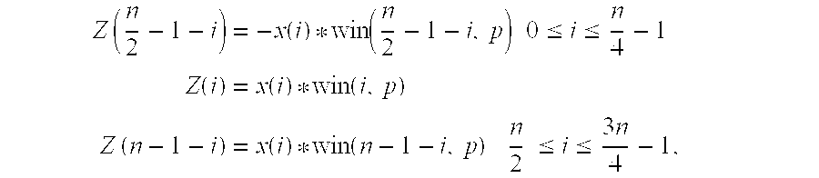
- where X(k) is the sub-band sample, Z(i) is the sub-band sample after process, when window type is 0, 1, 3, n equals 36; whereas when window type is 2, n equals 12. The equation (1) above indicates that the quantity of the operation can be reduced from n to n/2. That is, the quantity of the operation of the inverse-modified discrete cosine transform in the DWIMDCT can be reduced by half. Table 1 lists the comparison of the quantity of the operation of the original and the present invention. As shown in Table 1, when the window type is 0, 1, 3, the ratio of the present invention to the original is 0.48 MOPS (million operation per second). When the window type is 2, the ratio of the present invention to the original is 0.42 MOPS. Therefore, the quantity of the operation of the inverse-modified discrete cosine transform can be significantly reduced.
TABLE 1 Window Present Ratio Function Type Original Invention (MOPS) IMDCT Type 0, 1, 3 2.1 1 0.48 Type 21 0.42 0.42 - Afterwards, the entire hardware structure is implemented by using the fast algorithm. FIG. 3 schematically shows the hardware structure diagram of the inverse-modified discrete cosine transform and overlap-add hardware structure for MPEG Layer3 audio signal decoding of a preferred embodiment according to the present invention. The hardware structure comprises the
DWIMDCT module 30 and theDWIMDCT buffer memory 32. Wherein, theDWIMDCT module 30 mostly comprises the multiplier-adder (MACO) 302 and theregister stack 304. The operation method of the hardware structure is described hereafter. - At first, the multiplier-
adder 302 is utilized by the inverse-modified discrete cosine transform for calculation, and the final result is subsequently stored in theregister stack 304. Theregister stack 304 comprises 18 registers. After the operation of the inverse-modified discrete cosine transform, the overlap-add of the dynamic window is the follow-on operation. The operation of the overlap-add of the dynamic window is also accomplished by using the multiplier-adder 302, and the final result is stored in theDWIMDCT buffer memory 32. FIG. 4 schematically shows the layout diagram of theDWIMDCT buffer memory 32. As is shown in the diagram, theDWIMDCT buffer memory 32 comprises 3 memory banks (memory bank 0,memory bank 1 and memory bank 2), each memory bank can be further divided into 32 sub-band blocks, and each sub-band block is able to store 18 sample data. Furthermore, the hardware structure and the synthesis filter bank of the present invention are able to form a two-stage high performance pipeline process. The sequence of the DWIMDCT writing of the sample data contained in each memory bank of theDWIMDCT buffer memory 32 and the sequence of the reading of the synthesis filter bank are shown in FIG. 5. - The hardware structure of the inverse-modified discrete cosine transform and overlap-add for MPEG Layer3 audio signal decoding according to the present invention is easily compatible with the hardware of other modules, and is suitable for the design of the very large scale integration (VLSI). If the synthesis filter bank module can be integrated, the hardware utilization will be significantly enhanced, as will the operation performance of the entire decoder. Therefore, the MPEG Layer3 can be implemented by the ASIC, so that the entire system can fulfill the low cost and high performance requirements.
- In summary, the present invention bears the following advantages:
- 1. The present invention provides a low cost fast algorithm of the inverse-modified discrete cosine transform and overlap-add.
- 2. The present invention provides a hardware structure that is suitable for the inverse-modified discrete cosine transform and overlap-add in the MPEG Layer3 decoder.
- 3. The hardware structure of the present invention makes the MPEG Layer3 able to be implemented by the ASIC, so that the entire system fulfills the low cost and high performance requirements.
- Although the invention has been described with reference to a particular embodiment thereof, it will be apparent to one of the ordinary skill in the art that modifications to the described embodiment may be made without departing from the spirit of the invention. Accordingly, the scope of the invention will be defined by the attached claims not by the above detailed description.
Claims (16)





Priority Applications (1)
| Application Number | Priority Date | Filing Date | Title |
|---|---|---|---|
| US10/078,021 US7065491B2 (en) | 2002-02-15 | 2002-02-15 | Inverse-modified discrete cosine transform and overlap-add method and hardware structure for MPEG layer3 audio signal decoding |
Applications Claiming Priority (1)
| Application Number | Priority Date | Filing Date | Title |
|---|---|---|---|
| US10/078,021 US7065491B2 (en) | 2002-02-15 | 2002-02-15 | Inverse-modified discrete cosine transform and overlap-add method and hardware structure for MPEG layer3 audio signal decoding |
Publications (2)
| Publication Number | Publication Date |
|---|---|
| US20030158740A1 true US20030158740A1 (en) | 2003-08-21 |
| US7065491B2 US7065491B2 (en) | 2006-06-20 |
Family
ID=27732753
Family Applications (1)
| Application Number | Title | Priority Date | Filing Date |
|---|---|---|---|
| US10/078,021 Expired - Fee Related US7065491B2 (en) | 2002-02-15 | 2002-02-15 | Inverse-modified discrete cosine transform and overlap-add method and hardware structure for MPEG layer3 audio signal decoding |
Country Status (1)
| Country | Link |
|---|---|
| US (1) | US7065491B2 (en) |
Cited By (4)
| Publication number | Priority date | Publication date | Assignee | Title |
|---|---|---|---|---|
| CN100527850C (en) * | 2006-02-22 | 2009-08-12 | 广达电脑股份有限公司 | Method and apparatus for synthetic subband filtering in an audio signal decoder |
| US20090278995A1 (en) * | 2006-06-29 | 2009-11-12 | Oh Hyeon O | Method and apparatus for an audio signal processing |
| RU2806621C1 (en) * | 2009-01-16 | 2023-11-02 | Долби Интернешнл Аб | Harmonic transformation improved by cross product |
| US12119011B2 (en) | 2009-01-16 | 2024-10-15 | Dolby International Ab | Cross product enhanced harmonic transposition |
Families Citing this family (4)
| Publication number | Priority date | Publication date | Assignee | Title |
|---|---|---|---|---|
| US7418396B2 (en) * | 2003-10-14 | 2008-08-26 | Broadcom Corporation | Reduced memory implementation technique of filterbank and block switching for real-time audio applications |
| TWI227866B (en) * | 2003-11-07 | 2005-02-11 | Mediatek Inc | Subband analysis/synthesis filtering method |
| US7539870B2 (en) * | 2004-02-10 | 2009-05-26 | Microsoft Corporation | Media watermarking by biasing randomized statistics |
| KR100895100B1 (en) | 2007-01-31 | 2009-04-28 | 엠텍비젼 주식회사 | Method for decoding digital audio data and apparatus for decoding digital audio data |
Citations (9)
| Publication number | Priority date | Publication date | Assignee | Title |
|---|---|---|---|---|
| US5224213A (en) * | 1989-09-05 | 1993-06-29 | International Business Machines Corporation | Ping-pong data buffer for transferring data from one data bus to another data bus |
| US5566154A (en) * | 1993-10-08 | 1996-10-15 | Sony Corporation | Digital signal processing apparatus, digital signal processing method and data recording medium |
| US5608713A (en) * | 1994-02-09 | 1997-03-04 | Sony Corporation | Bit allocation of digital audio signal blocks by non-linear processing |
| US5654952A (en) * | 1994-10-28 | 1997-08-05 | Sony Corporation | Digital signal encoding method and apparatus and recording medium |
| US5867819A (en) * | 1995-09-29 | 1999-02-02 | Nippon Steel Corporation | Audio decoder |
| US5899970A (en) * | 1993-06-30 | 1999-05-04 | Sony Corporation | Method and apparatus for encoding digital signal method and apparatus for decoding digital signal, and recording medium for encoded signals |
| US6166663A (en) * | 1999-07-16 | 2000-12-26 | National Science Council | Architecture for inverse quantization and multichannel processing in MPEG-II audio decoding |
| US6199039B1 (en) * | 1998-08-03 | 2001-03-06 | National Science Council | Synthesis subband filter in MPEG-II audio decoding |
| US20020106020A1 (en) * | 2000-02-09 | 2002-08-08 | Cheng T. C. | Fast method for the forward and inverse MDCT in audio coding |
-
2002
- 2002-02-15 US US10/078,021 patent/US7065491B2/en not_active Expired - Fee Related
Patent Citations (9)
| Publication number | Priority date | Publication date | Assignee | Title |
|---|---|---|---|---|
| US5224213A (en) * | 1989-09-05 | 1993-06-29 | International Business Machines Corporation | Ping-pong data buffer for transferring data from one data bus to another data bus |
| US5899970A (en) * | 1993-06-30 | 1999-05-04 | Sony Corporation | Method and apparatus for encoding digital signal method and apparatus for decoding digital signal, and recording medium for encoded signals |
| US5566154A (en) * | 1993-10-08 | 1996-10-15 | Sony Corporation | Digital signal processing apparatus, digital signal processing method and data recording medium |
| US5608713A (en) * | 1994-02-09 | 1997-03-04 | Sony Corporation | Bit allocation of digital audio signal blocks by non-linear processing |
| US5654952A (en) * | 1994-10-28 | 1997-08-05 | Sony Corporation | Digital signal encoding method and apparatus and recording medium |
| US5867819A (en) * | 1995-09-29 | 1999-02-02 | Nippon Steel Corporation | Audio decoder |
| US6199039B1 (en) * | 1998-08-03 | 2001-03-06 | National Science Council | Synthesis subband filter in MPEG-II audio decoding |
| US6166663A (en) * | 1999-07-16 | 2000-12-26 | National Science Council | Architecture for inverse quantization and multichannel processing in MPEG-II audio decoding |
| US20020106020A1 (en) * | 2000-02-09 | 2002-08-08 | Cheng T. C. | Fast method for the forward and inverse MDCT in audio coding |
Cited By (6)
| Publication number | Priority date | Publication date | Assignee | Title |
|---|---|---|---|---|
| CN100527850C (en) * | 2006-02-22 | 2009-08-12 | 广达电脑股份有限公司 | Method and apparatus for synthetic subband filtering in an audio signal decoder |
| US20090278995A1 (en) * | 2006-06-29 | 2009-11-12 | Oh Hyeon O | Method and apparatus for an audio signal processing |
| US8326609B2 (en) * | 2006-06-29 | 2012-12-04 | Lg Electronics Inc. | Method and apparatus for an audio signal processing |
| RU2806621C1 (en) * | 2009-01-16 | 2023-11-02 | Долби Интернешнл Аб | Harmonic transformation improved by cross product |
| US12119011B2 (en) | 2009-01-16 | 2024-10-15 | Dolby International Ab | Cross product enhanced harmonic transposition |
| US12165666B2 (en) | 2009-01-16 | 2024-12-10 | Dolby International Ab | Cross product enhanced harmonic transposition |
Also Published As
| Publication number | Publication date |
|---|---|
| US7065491B2 (en) | 2006-06-20 |
Similar Documents
| Publication | Publication Date | Title |
|---|---|---|
| ES2733878T3 (en) | Enhanced coding of multichannel digital audio signals | |
| JP5291815B2 (en) | Scaleable coding using hierarchical filter banks | |
| KR100947013B1 (en) | Temporal and spatial shaping of multi-channel audio signals | |
| US6295009B1 (en) | Audio signal encoding apparatus and method and decoding apparatus and method which eliminate bit allocation information from the encoded data stream to thereby enable reduction of encoding/decoding delay times without increasing the bit rate | |
| CN112735447B (en) | Method and apparatus for compressing and decompressing a higher order ambisonics signal representation | |
| CN100546233C (en) | Method and device for supporting multi-channel audio extension | |
| KR101168473B1 (en) | Audio encoding system | |
| AU2005337961A1 (en) | Audio compression | |
| JP5163545B2 (en) | Audio decoding apparatus and audio decoding method | |
| CN101371447A (en) | Complex transform channel coding using spread band frequency coding | |
| KR101966782B1 (en) | Delay-optimized overlap transform, coding/decoding weighting windows | |
| JP2002204170A (en) | Multi-stage coding of signal components classified by component values | |
| EP1969593B1 (en) | Multiple description coding using correlating transforms | |
| TW569550B (en) | Method of inverse-modified discrete cosine transform and overlap-add for MPEG layer 3 voice signal decoding and apparatus thereof | |
| CN102365680A (en) | Audio signal encoding and decoding method, and apparatus for same | |
| CN100489965C (en) | Audio encoding system | |
| CN114898761A (en) | Stereo signal coding and decoding method and device | |
| US20020169601A1 (en) | Encoding device, decoding device, and broadcast system | |
| US7065491B2 (en) | Inverse-modified discrete cosine transform and overlap-add method and hardware structure for MPEG layer3 audio signal decoding | |
| KR100750115B1 (en) | Audio signal encoding and decoding method and apparatus therefor | |
| CN1138254C (en) | Audio signal comprssing coding/decoding method based on wavelet conversion | |
| US20040010329A1 (en) | Method for reducing buffer requirements in a digital audio decoder | |
| US20080133250A1 (en) | Method and Related Device for Improving the Processing of MP3 Decoding and Encoding | |
| CN109389985A (en) | Time Domain Stereo Codec Methods and Related Products | |
| CN1318904A (en) | Practical sound coder based on wavelet conversion |
Legal Events
| Date | Code | Title | Description |
|---|---|---|---|
| AS | Assignment |
Owner name: NATIONAL CENTRAL UNIVERSITY, TAIWAN Free format text: ASSIGNMENT OF ASSIGNORS INTEREST;ASSIGNORS:TSAI, TSUNG-HAN;YANG, YA-CHAU;REEL/FRAME:012620/0751 Effective date: 20020124 |
|
| FPAY | Fee payment |
Year of fee payment: 4 |
|
| FPAY | Fee payment |
Year of fee payment: 8 |
|
| FEPP | Fee payment procedure |
Free format text: MAINTENANCE FEE REMINDER MAILED (ORIGINAL EVENT CODE: REM.) |
|
| LAPS | Lapse for failure to pay maintenance fees |
Free format text: PATENT EXPIRED FOR FAILURE TO PAY MAINTENANCE FEES (ORIGINAL EVENT CODE: EXP.) |
|
| STCH | Information on status: patent discontinuation |
Free format text: PATENT EXPIRED DUE TO NONPAYMENT OF MAINTENANCE FEES UNDER 37 CFR 1.362 |
|
| FP | Lapsed due to failure to pay maintenance fee |
Effective date: 20180620 |
|
| FP | Lapsed due to failure to pay maintenance fee |
Effective date: 20180620 |