US1925877A - Pasteurizing apparatus - Google Patents
Pasteurizing apparatus Download PDFInfo
- Publication number
- US1925877A US1925877A US527926A US52792631A US1925877A US 1925877 A US1925877 A US 1925877A US 527926 A US527926 A US 527926A US 52792631 A US52792631 A US 52792631A US 1925877 A US1925877 A US 1925877A
- Authority
- US
- United States
- Prior art keywords
- tank
- pipe
- jacket space
- pump
- circulation
- Prior art date
- Legal status (The legal status is an assumption and is not a legal conclusion. Google has not performed a legal analysis and makes no representation as to the accuracy of the status listed.)
- Expired - Lifetime
Links
- 238000010438 heat treatment Methods 0.000 description 15
- 239000007788 liquid Substances 0.000 description 9
- XLYOFNOQVPJJNP-UHFFFAOYSA-N water Substances O XLYOFNOQVPJJNP-UHFFFAOYSA-N 0.000 description 9
- 239000012267 brine Substances 0.000 description 6
- 238000005266 casting Methods 0.000 description 6
- HPALAKNZSZLMCH-UHFFFAOYSA-M sodium;chloride;hydrate Chemical compound O.[Na+].[Cl-] HPALAKNZSZLMCH-UHFFFAOYSA-M 0.000 description 6
- 238000010276 construction Methods 0.000 description 5
- 230000009471 action Effects 0.000 description 4
- 238000001816 cooling Methods 0.000 description 4
- 235000013336 milk Nutrition 0.000 description 4
- 210000004080 milk Anatomy 0.000 description 4
- 239000008267 milk Substances 0.000 description 4
- 235000019645 odor Nutrition 0.000 description 4
- 239000002826 coolant Substances 0.000 description 3
- 239000012530 fluid Substances 0.000 description 3
- 239000006260 foam Substances 0.000 description 3
- 239000003517 fume Substances 0.000 description 3
- 238000000034 method Methods 0.000 description 3
- 239000000047 product Substances 0.000 description 3
- 238000005086 pumping Methods 0.000 description 3
- 238000009833 condensation Methods 0.000 description 2
- 230000005494 condensation Effects 0.000 description 2
- 230000007246 mechanism Effects 0.000 description 2
- 239000002184 metal Substances 0.000 description 2
- 238000009928 pasteurization Methods 0.000 description 2
- 210000002966 serum Anatomy 0.000 description 2
- 241000894006 Bacteria Species 0.000 description 1
- 229910000906 Bronze Inorganic materials 0.000 description 1
- 238000013019 agitation Methods 0.000 description 1
- 230000001580 bacterial effect Effects 0.000 description 1
- 239000011324 bead Substances 0.000 description 1
- 239000010974 bronze Substances 0.000 description 1
- KUNSUQLRTQLHQQ-UHFFFAOYSA-N copper tin Chemical compound [Cu].[Sn] KUNSUQLRTQLHQQ-UHFFFAOYSA-N 0.000 description 1
- 235000013365 dairy product Nutrition 0.000 description 1
- 230000002939 deleterious effect Effects 0.000 description 1
- 238000007599 discharging Methods 0.000 description 1
- 230000000694 effects Effects 0.000 description 1
- 230000008030 elimination Effects 0.000 description 1
- 238000003379 elimination reaction Methods 0.000 description 1
- 230000002349 favourable effect Effects 0.000 description 1
- 239000012467 final product Substances 0.000 description 1
- 239000007789 gas Substances 0.000 description 1
- 239000004615 ingredient Substances 0.000 description 1
- 230000004048 modification Effects 0.000 description 1
- 238000012986 modification Methods 0.000 description 1
- 230000008569 process Effects 0.000 description 1
- 235000020185 raw untreated milk Nutrition 0.000 description 1
- 230000001105 regulatory effect Effects 0.000 description 1
- 230000006903 response to temperature Effects 0.000 description 1
- 239000007921 spray Substances 0.000 description 1
- 210000003813 thumb Anatomy 0.000 description 1
Images

Classifications
-
- A—HUMAN NECESSITIES
- A23—FOODS OR FOODSTUFFS; TREATMENT THEREOF, NOT COVERED BY OTHER CLASSES
- A23B—PRESERVATION OF FOODS, FOODSTUFFS OR NON-ALCOHOLIC BEVERAGES; CHEMICAL RIPENING OF FRUIT OR VEGETABLES
- A23B11/00—Preservation of milk or dairy products
- A23B11/10—Preservation of milk or milk preparations
- A23B11/12—Preservation of milk or milk preparations by heating
- A23B11/13—Preservation of milk or milk preparations by heating the materials being loose unpacked
- A23B11/1303—Apparatus through which the material is transported non progressively; Temperature-maintaining holding tanks or vats with discontinuous filling or discharge
Definitions
- the present invention has reference topasteurizing apparatus, such as is required for pasteurizing operations in dairy or serum plants, for the pasteurization of milk, serums, or other products 51 requiring a treatment of this character, and the 7 primary object of the invention is to devise a novel and more eflicient pasteurizing equipment for this work.
- the invention comprises as one of its primary features an apparatus designed for the pasteurizing treatment of successive batches ofmilk or the like, in the operation of which the receptacle forithe batch is completely submerged in the heating medium, in order to. effect a thorough and complete pasteurizing treatment of the batch, throughout all portions of the same. 7
- the construction of the equipment is such as to facilitate a like treatment of the batch by subjection of the receptacle containing the same to a cooling action upon' all sides thereof, whereby all the contents of the receptacle are subjected to the-same, equal, uniform treatment.
- a receptacle which is mounted within an outside container in such relation that a complete jacket space is affordedentirely surrounding the batch-containing receptacle, togetherwithmeans for circulating a heating medium throughout said jacket space, the illustrated construction includingna thermostatically controlled steamor hot water supply and pump mechanism for maintaining the necessary circulation, and at the temperature required for efiicient pasteurization.
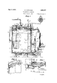
- FIG. 1 is a side elevation illustrating a pas teurizing equipment, constructed in accordance with said invention
- Figure 2 is a plan view of the same
- Figure 3 is a central vertical sectional View, on a larger scale
- Figure 4 is an enlarged sectional detail of the upperportion of the jacket space structure.
- Figure 5 is an enlarged sectional view of the 5 flush valve for the inner tank.
- FIG. 1 illustrates the improved apparatus as comprising anopen topped outer tank 10 supported by suitable legs 11 and enclosing a closed inner batch- 7 receiving tank 12 supported in spaced relation within the tank 10 by a number of brackets 14 formed with horizontal supporting ledges 15, as shown in Figure 3.
- the top of the inner tank 12 is provided with a casting '16 of suitable metal 7 (such as tinned bronze) surrounding an opening 1'7 adapted to be sealed by a cover member 18 of similar metal carrying a gasket 19 engaged by a bead 20 formed on'the casting 16;
- the cover swings on a hinge 21, and is adapted to be tightly. closed byhinged bolts 22 carrying thumb nuts 23 for clamping engagement with the several forked projections 24 of the cover.
- a jacket space 25 is provided between the inner and outer tanks, andthe latter is of sufiiciently greater depth than the inner tank to completely submerge the same when a flow of the heating or cooling medium is maintained through said'space by the following described connections.
- water may be introduced through a pipe 30, from which two branches 31 are connected'tangentially with the bottom portion of the tank 10, and intermediate said connections the pipe 30 is connected with the discharge of a-rotary pump 32 driven by a suitable motor 29, the intake of the pump being connected by apipe 33 with the bottom of a heating drum 34.
- a water return pipe 36 leading tangentially from thetop of thetank 10, as shown in Figure 3.
- the connecting pipe 33 between the pump and drum 34 includes a T 38 for connection with a water line 39 (for initially filling the. system) and also with a steam line' lO for injecting live steam into the drum for water-heating purposes, the steam supply being automatically regulated by a valve 41 controlled by a thermostat 42 of ordinary and well-known construction and installed for response to temperature conditions in the drum.
- a pipe 35 serves as an overflow or drain pipe connecting with the top of the outer tank, as the water level rises due to steam condensation (see Figures 1 and 2).
- an intake pipe connection 50 is attached to the upper end portion of the tank 10, communicating with any suitable source (not shown) of brine'supply and terminating in a perforated ring 52 surrounding the interior of the tank 10 and having its perforations 53 facing inwardly in position to spray the brine over the cover 18 of the tank 12.
- the pipes 31 are closed by valves 54 and the brine or other cooling medium withdrawn through a bottom outlet pipe 56 com- 16 municating with the pump intake pipe 33, which is also closedabove the pump by the valvet'l.
- the brine is returned from the pump to the brine supply by way of the pipe 30 and an extension pipe 58, this pipe as well as the pipe 56 being:
- the lower end of the pipe 33 may also be fitted with a suitable valve 60 for drainage purposes, and the pipe 56 may also be provided with a drain age outlet as indicated at 62 Figures 1 and 3).
- the cover member 18 of the tank'12 is provided, with a casting 63 formed with a vertical bearing sleeve 64 lined with an oilless type of bushing 65 fora vertical shaft rod 66 carrying a stirrer device 67, which is thus operatively suspended within the tank 12 for maintainingconstant agitation of the liquid -therein.
- the upper end of. the shaft rod 66 carries a pulley 68 driven by a belt 69 from a suitable reducing gear device 70 which is driven by a belt'71 from a motor 72' carried by ashelf 73 at the exterior of the tank 10, said driving mechanism preferably being enclosed by a-housing '14.
- the shaft 66 also carries a cup element '75 above the level of the liquid in the tank 12, as shown in Figure 3, to trap any foreign matter which might drain down the shaft from exterior or from above the cup.
- a perforated ring member '77 is' also mounted upon the top of the inner tank 12, theperforations '76 permitting the passage of the liquid but serving to strain theliquid of any foreign matter, 7
- I provide a combination suction and 'pressure pipe connection communicating with the interior of the tank through the top portion thereof, and provided with'an externalT 81 connecting with a pipe 82 communicating with any suitable source of air supply, and also with another vent pipe 83 fitted with a valve 84.
- the airi flow will extract the fumes, odors and the like, through the influence of the vacuum produced in the top of the tank 12, and the same vacuum action may be utilized for filling the tank, as under conditions requiring the milk or other liquid to be brought up from a slightly lower level; and again, the tank 12 may be conveniently emptied. byair pressure admitted from" the pipe 82 (the valve 84 being closed) and the contents rapidly discharged to'any desired point. a
- the discharge from the tank 12 is by way of a flush-valve structure shown in more detail in Figure 5, and comprising a casting 85 secured to the shell of the tank and formed with'a concave flange 8 7 embracing the bottom of the tank and providing a'sloping passage to the discharge opening 88; 'a'shoulder clamping ring 89 is screwed into the casting 85 for securing the same in clamping engagement with the margin of an opening 90in the outer tank 10.
- a valve 92 provided with an exterior operating handle 93 controls the flow through the opening 88'to an outlet 9; in the body of the casting, all the passages being of ample size for quick-flowing action.
- thepump is operated to 'submer'gence' of the container in the water as this operation takes place insures a thorough and eilective-treatment of all the contents of the container, including any foam or vapor in the top of'same; which is a most important feature in pasteuriz'ing operations, both 1 as regards the heating and cooling steps of the process.
- foam and vapors are more difiicult to heat and cool than the liquid, and if not properly treated they are simply left in a state more favorable for the propagation of bacteria than before.
- the'vacuum connection 80 is provided "for continuously removing vapors, and odors, as fast as practicable, to reduce condensation to a minimum; and anyvapors and foam remaining being also completely submerged in the'treating medium, are heated, and later cooled, to the same temperature as the remaining contents of the container.
- the facility with which the contents of the container may be cooled at a very rapid rlate is also an important feature of the invention, since the cooling operation should be carried out asspeedily as possible to bring the temperature below that favoring the bacterial growth, with no unnecessary delay,
- one very important feature of merit characterizes the improved apparatus in that the pasteurizing operation can be carried out with the lowest temperatures practicable for such treatment, due to the efficient and therefore rapid method of heat exchange, which is effective in preserving the raw milk fiavor in the final product.
- any efficient heating unit may be adapted for the purpose, and one unit made to serve two or more batch-treating units, if deemed desirable.
- Apparatus of the character described comprising an outer open top tank, an inner tank enclosed within said outer tank in spaced relation to both the bottom and side walls of the latter and provided with a liquid-tight cover accessible through the upper end of the outer tank, and means for maintaining a circulation of a fluid-heating medium through the space between said tanks, said outer tank being of a depth sufficient to completely submerge the inner tank in said fluid-heating medium.
- Apparatus of the character described comprising an inner closed tank and an outer tank providing a jacket space entirely surrounding both the sides and bottom of and completely submerging said inner tank, and pumping means provided with a heating device and operative to maintain a circulation of a hot fluid-heating medium through said jacket space, said pumping means being also provided with tangential connections to said jacket space for circulating a cold fluid-treating medium therethrough.
- Apparatus of the character described comprising an inner closed tank and an outer tank providing a jacket space entirely surrounding and completely submerging said inner tank, and a pump provided with a plurality of tangential connections communicating at different levels with the lower part of said jacket space and also with a fluid return connection communicating tangentially with the upper portion of said jacket space, whereby a continuous circulation of fluid-heating medium is maintained through said jacket space.
- Apparatus of the character described comprising an inner closed tank and an outer tank providing a jacket space entirely surrounding and completely submerging said inner tank, and a pump provided with tangential connections to said jacket space for maintaining a continuous circulation of fluid-treating medium therethrough, said connections including a heating device for stepping up the temperature of the fluid on its return passage from said jacket space to the pump.
- Apparatus of the character described comprising an inner closed tank and an outer tank providing a jacket space entirely surrounding and completely submerging said inner tank, and means for maintaining a circulation of a fluidheating medium through said jacket space and including a perforated ring surrounding the upper closed end of said inner tank.
- Pasteurizing apparatus comprising an inner closed tank and an outer tank providing a jacket space entirely surrounding and completely submerging said inner tank, means for maintaining a hot fluid circulation through said jacket space, and a combination pressure and vacuum connection communicating with the inner tank above the liquid level therein and oper ative for either filling or expelling the contents from the inner tank.
Landscapes
- Life Sciences & Earth Sciences (AREA)
- Engineering & Computer Science (AREA)
- Wood Science & Technology (AREA)
- Zoology (AREA)
- Chemical & Material Sciences (AREA)
- Food Science & Technology (AREA)
- Polymers & Plastics (AREA)
- Dairy Products (AREA)
Description
Sept. 5, 1933. Q E M|THUM 1,925,877
PASTEURI Z ING APPARATUS Filed April 6, 1931 2 Sheets-Sheet 1 A TTORNEY.
Sept. 5, 1933. Q E, WTCHUM 1,925,877
PASTEURIZING APPARATUS Filed April 6, 1931 2 Sheets-Sheet 2 A TTORNEY.
Patented Sept. 5, 1933 PATENT OFFICE 1,925,877. I PASTEURIZING APPARATUS Cecil E. Mitchum, Kansas City, Kans.
Application April 6, 1931.- Serial No. 527,926-
6 Claims.
The present invention has reference topasteurizing apparatus, such as is required for pasteurizing operations in dairy or serum plants, for the pasteurization of milk, serums, or other products 51 requiring a treatment of this character, and the 7 primary object of the invention is to devise a novel and more eflicient pasteurizing equipment for this work. v
Accordingly, the invention comprises as one of its primary features an apparatus designed for the pasteurizing treatment of successive batches ofmilk or the like, in the operation of which the receptacle forithe batch is completely submerged in the heating medium, in order to. effect a thorough and complete pasteurizing treatment of the batch, throughout all portions of the same. 7
Likewise, the construction of the equipment is such as to facilitate a like treatment of the batch by subjection of the receptacle containing the same to a cooling action upon' all sides thereof, whereby all the contents of the receptacle are subjected to the-same, equal, uniform treatment.
In carrying out myinvention, in practice, I
provide a receptacle which is mounted within an outside container in such relation that a complete jacket space is affordedentirely surrounding the batch-containing receptacle, togetherwithmeans for circulating a heating medium throughout said jacket space, the illustrated construction includingna thermostatically controlled steamor hot water supply and pump mechanism for maintaining the necessary circulation, and at the temperature required for efiicient pasteurization.
Further features of the invention comprise means for agitatingthe batch within the re= ceptacle, also means for maintaining'circulation of a suitable cooling mediumwithin the jacket space referredto, for lowering the temperature "of-the contents of the receptacle, means for extracting vapor, fumes or odors from the top' surface of the batch within the-receptacle, and also means'for discharging or refilling the receptacle with a new'supply of the-liquid to be pasteurized, by pressure or vacuum action, as hereinafter more fully-explained. p
With the foregoing general objects in view, as well as variousminor features ofthe same, as will be more particularlyexplained, the invention will now be described by reference to the accompanying drawings illustrating one suitable, practical form of embodiment of the proposed features chimpmvement,after-which those features and combinations thereof ,deemedtobe novel will be set forth in proper claims. 7
In the drawings- Figure 1 is a side elevation illustrating a pas teurizing equipment, constructed in accordance with said invention;
Figure 2 is a plan view of the same;
Figure 3 is a central vertical sectional View, on a larger scale;
Figure 4 is an enlarged sectional detail of the upperportion of the jacket space structure; and
Figure 5 is an enlarged sectional view of the 5 flush valve for the inner tank.
Referring now to the drawings in detail, these illustrate the improved apparatus as comprising anopen topped outer tank 10 supported by suitable legs 11 and enclosing a closed inner batch- 7 receiving tank 12 supported in spaced relation within the tank 10 by a number of brackets 14 formed with horizontal supporting ledges 15, as shown in Figure 3. The top of the inner tank 12 is provided with a casting '16 of suitable metal 7 (such as tinned bronze) surrounding an opening 1'7 adapted to be sealed by a cover member 18 of similar metal carrying a gasket 19 engaged by a bead 20 formed on'the casting 16; The cover swings on a hinge 21, and is adapted to be tightly. closed byhinged bolts 22 carrying thumb nuts 23 for clamping engagement with the several forked projections 24 of the cover.
Thus a jacket space 25 is provided between the inner and outer tanks, andthe latter is of sufiiciently greater depth than the inner tank to completely submerge the same when a flow of the heating or cooling medium is maintained through said'space by the following described connections.
For maintaining the required circulation of a heating medium, water may be introduced through a pipe 30, from which two branches 31 are connected'tangentially with the bottom portion of the tank 10, and intermediate said connections the pipe 30 is connected with the discharge of a-rotary pump 32 driven by a suitable motor 29, the intake of the pump being connected by apipe 33 with the bottom of a heating drum 34. To the top, of thisheating drum34'is con nected a water return pipe 36 leading tangentially from thetop of thetank 10, as shown in Figure 3. i
The connecting pipe 33 between the pump and drum 34 includes a T 38 for connection with a water line 39 (for initially filling the. system) and also witha steam line' lO for injecting live steam into the drum for water-heating purposes, the steam supply being automatically regulated by a valve 41 controlled by a thermostat 42 of ordinary and well-known construction and installed for response to temperature conditions in the drum. A pipe 35 serves as an overflow or drain pipe connecting with the top of the outer tank, as the water level rises due to steam condensation (see Figures 1 and 2).
With the connections as above described, the operation of the pump will maintain a hot water circulation, in' through the lower pipes 31, through the jacket space and out throughthe upper pipe 36 by which the water is returned I I also be provided in connection with the pump intake pipe 33, as illustrated in Figure 1.
For circulating brine or other liquid cooling medium through the jacket space 25' surrounding the batch-receiving tank 12, an intake pipe connection 50 is attached to the upper end portion of the tank 10, communicating with any suitable source (not shown) of brine'supply and terminating in a perforated ring 52 surrounding the interior of the tank 10 and having its perforations 53 facing inwardly in position to spray the brine over the cover 18 of the tank 12.
In this operation the pipes 31 are closed by valves 54 and the brine or other cooling medium withdrawn through a bottom outlet pipe 56 com- 16 municating with the pump intake pipe 33, which is also closedabove the pump by the valvet'l. The brine is returned from the pump to the brine supply by way of the pipe 30 and an extension pipe 58, this pipe as well as the pipe 56 being:
provided witlrvalves 58' and 56', respectively, for
closing the same during the hot water circulation. The lower end of the pipe 33 may also be fitted with a suitable valve 60 for drainage purposes, and the pipe 56 may also be provided witha drain age outlet as indicated at 62 Figures 1 and 3).
The cover member 18 of the tank'12 is provided, with a casting 63 formed with a vertical bearing sleeve 64 lined with an oilless type of bushing 65 fora vertical shaft rod 66 carrying a stirrer device 67, which is thus operatively suspended within the tank 12 for maintainingconstant agitation of the liquid -therein. The upper end of. the shaft rod 66 carries a pulley 68 driven by a belt 69 from a suitable reducing gear device 70 which is driven by a belt'71 from a motor 72' carried by ashelf 73 at the exterior of the tank 10, said driving mechanism preferably being enclosed by a-housing '14. The shaft 66 also carries a cup element '75 above the level of the liquid in the tank 12, as shown in Figure 3, to trap any foreign matter which might drain down the shaft from exterior or from above the cup. A perforated ring member '77 is' also mounted upon the top of the inner tank 12, theperforations '76 permitting the passage of the liquid but serving to strain theliquid of any foreign matter, 7
As certain gases, fumes, odors, etc., may be generated above the liquid level in the tank 12, it is preferable to withdraw these as continuously as possible, and for this purpose as well as for use in draining or filling said tank, under certain conditions, I provide a combination suction and 'pressure pipe connection communicating with the interior of the tank through the top portion thereof, and provided with'an externalT 81 connecting with a pipe 82 communicating with any suitable source of air supply, and also with another vent pipe 83 fitted with a valve 84. By
means of this arrangement, on opening the valve 8 4, the airi flow will extract the fumes, odors and the like, through the influence of the vacuum produced in the top of the tank 12, and the same vacuum action may be utilized for filling the tank, as under conditions requiring the milk or other liquid to be brought up from a slightly lower level; and again, the tank 12 may be conveniently emptied. byair pressure admitted from" the pipe 82 (the valve 84 being closed) and the contents rapidly discharged to'any desired point. a
The discharge from the tank 12 is by way of a flush-valve structure shown in more detail in Figure 5, and comprising a casting 85 secured to the shell of the tank and formed with'a concave flange 8 7 embracing the bottom of the tank and providing a'sloping passage to the discharge opening 88; 'a'shoulder clamping ring 89 is screwed into the casting 85 for securing the same in clamping engagement with the margin of an opening 90in the outer tank 10. A valve 92 provided with an exterior operating handle 93 controls the flow through the opening 88'to an outlet 9; in the body of the casting, all the passages being of ample size for quick-flowing action.
- Inthe' operation, thepump is operated to 'submer'gence' of the container in the water as this operation takes place insures a thorough and eilective-treatment of all the contents of the container, including any foam or vapor in the top of'same; which is a most important feature in pasteuriz'ing operations, both 1 as regards the heating and cooling steps of the process. For the foam and vapors are more difiicult to heat and cool than the liquid, and if not properly treated they are simply left in a state more favorable for the propagation of bacteria than before.
For this reason the'vacuum connection 80 is provided "for continuously removing vapors, and odors, as fast as practicable, to reduce condensation to a minimum; and anyvapors and foam remaining being also completely submerged in the'treating medium, are heated, and later cooled, to the same temperature as the remaining contents of the container. The facility with which the contents of the container may be cooled at a very rapid rlateis also an important feature of the invention, since the cooling operation should be carried out asspeedily as possible to bring the temperature below that favoring the bacterial growth, with no unnecessary delay,
This is important also as a factor in helping to set the butter-fat ingredients and to promote the superior quality of the product, where milk is being treated.
In this connection one very important feature of merit characterizes the improved apparatus in that the pasteurizing operation can be carried out with the lowest temperatures practicable for such treatment, due to the efficient and therefore rapid method of heat exchange, which is effective in preserving the raw milk fiavor in the final product.
The provision made for filling and emptying the inner tank or container renders the apparatus most convenient and elficient in these stages of the operation, and the elimination of pumping as far as possible in the treatment of milk is desirable, since it is well-known that this has a very deleterious effect upon the grade of the product.
While I have shown a method of utilizing steam as the heating medium, any efficient heating unit may be adapted for the purpose, and one unit made to serve two or more batch-treating units, if deemed desirable.
It is therefore apparent that I have devised a practical and efiicient arrangement and construction of apparatus for carrying out the desired objects of the invention, and while the illustrated type of construction is well adapted for the practice of the invention it is obvious that minor variations may be made within the principles thereof; I therefore desire to be understood as reserving the right to make whatever changes or modifications may fairly fall within the scope of the appended claims.
What I claim is:
1. Apparatus of the character described comprising an outer open top tank, an inner tank enclosed within said outer tank in spaced relation to both the bottom and side walls of the latter and provided with a liquid-tight cover accessible through the upper end of the outer tank, and means for maintaining a circulation of a fluid-heating medium through the space between said tanks, said outer tank being of a depth sufficient to completely submerge the inner tank in said fluid-heating medium.
2. Apparatus of the character described comprising an inner closed tank and an outer tank providing a jacket space entirely surrounding both the sides and bottom of and completely submerging said inner tank, and pumping means provided with a heating device and operative to maintain a circulation of a hot fluid-heating medium through said jacket space, said pumping means being also provided with tangential connections to said jacket space for circulating a cold fluid-treating medium therethrough.
3. Apparatus of the character described comprising an inner closed tank and an outer tank providing a jacket space entirely surrounding and completely submerging said inner tank, and a pump provided with a plurality of tangential connections communicating at different levels with the lower part of said jacket space and also with a fluid return connection communicating tangentially with the upper portion of said jacket space, whereby a continuous circulation of fluid-heating medium is maintained through said jacket space.
4. Apparatus of the character described comprising an inner closed tank and an outer tank providing a jacket space entirely surrounding and completely submerging said inner tank, and a pump provided with tangential connections to said jacket space for maintaining a continuous circulation of fluid-treating medium therethrough, said connections including a heating device for stepping up the temperature of the fluid on its return passage from said jacket space to the pump.
5. Apparatus of the character described comprising an inner closed tank and an outer tank providing a jacket space entirely surrounding and completely submerging said inner tank, and means for maintaining a circulation of a fluidheating medium through said jacket space and including a perforated ring surrounding the upper closed end of said inner tank.
6. Pasteurizing apparatus comprising an inner closed tank and an outer tank providing a jacket space entirely surrounding and completely submerging said inner tank, means for maintaining a hot fluid circulation through said jacket space, and a combination pressure and vacuum connection communicating with the inner tank above the liquid level therein and oper ative for either filling or expelling the contents from the inner tank.
Priority Applications (1)
| Application Number | Priority Date | Filing Date | Title |
|---|---|---|---|
| US527926A US1925877A (en) | 1931-04-06 | 1931-04-06 | Pasteurizing apparatus |
Applications Claiming Priority (1)
| Application Number | Priority Date | Filing Date | Title |
|---|---|---|---|
| US527926A US1925877A (en) | 1931-04-06 | 1931-04-06 | Pasteurizing apparatus |
Publications (1)
| Publication Number | Publication Date |
|---|---|
| US1925877A true US1925877A (en) | 1933-09-05 |
Family
ID=24103525
Family Applications (1)
| Application Number | Title | Priority Date | Filing Date |
|---|---|---|---|
| US527926A Expired - Lifetime US1925877A (en) | 1931-04-06 | 1931-04-06 | Pasteurizing apparatus |
Country Status (1)
| Country | Link |
|---|---|
| US (1) | US1925877A (en) |
Cited By (12)
| Publication number | Priority date | Publication date | Assignee | Title |
|---|---|---|---|---|
| US2427146A (en) * | 1944-07-15 | 1947-09-09 | William T Lee | Pasteurizer |
| US2607566A (en) * | 1949-10-21 | 1952-08-19 | Guard It Mfg Company | Pasteurizer |
| US2697486A (en) * | 1950-12-28 | 1954-12-21 | Swift & Co | Antibridginc apparatus |
| US2702019A (en) * | 1952-09-26 | 1955-02-15 | Zero Mfg Company | Vacuum container milking system and apparatus therefor |
| US2739568A (en) * | 1954-04-26 | 1956-03-27 | Zero Mfg Company | Vacuum container milking system and apparatus therefor |
| US2763240A (en) * | 1953-10-16 | 1956-09-18 | Zero Mfg Company | Means for milking and handling the milk of farm animals |
| US2865391A (en) * | 1955-02-16 | 1958-12-23 | Lloyd P Duncan | Means for filling a bulk milk container from one or more milk cans |
| US3403528A (en) * | 1961-03-30 | 1968-10-01 | Singmaster & Breyer | Vacuum cooling for multi-stage chemical processes |
| US3872869A (en) * | 1973-08-02 | 1975-03-25 | Arthur J Randolph | Poultry semen collecting apparatus |
| US20170312327A1 (en) * | 2014-11-17 | 2017-11-02 | Connoisseur Holdings, Llc | Extraction devices, systems, and methods |
| US9844740B2 (en) * | 2014-11-17 | 2017-12-19 | Connoisseur Holdings, Llc | Extraction devices, systems, and methods |
| US11015142B1 (en) * | 2016-10-20 | 2021-05-25 | Unified Science, LLC | Extraction system and methods for preparing a botanical oil |
-
1931
- 1931-04-06 US US527926A patent/US1925877A/en not_active Expired - Lifetime
Cited By (12)
| Publication number | Priority date | Publication date | Assignee | Title |
|---|---|---|---|---|
| US2427146A (en) * | 1944-07-15 | 1947-09-09 | William T Lee | Pasteurizer |
| US2607566A (en) * | 1949-10-21 | 1952-08-19 | Guard It Mfg Company | Pasteurizer |
| US2697486A (en) * | 1950-12-28 | 1954-12-21 | Swift & Co | Antibridginc apparatus |
| US2702019A (en) * | 1952-09-26 | 1955-02-15 | Zero Mfg Company | Vacuum container milking system and apparatus therefor |
| US2763240A (en) * | 1953-10-16 | 1956-09-18 | Zero Mfg Company | Means for milking and handling the milk of farm animals |
| US2739568A (en) * | 1954-04-26 | 1956-03-27 | Zero Mfg Company | Vacuum container milking system and apparatus therefor |
| US2865391A (en) * | 1955-02-16 | 1958-12-23 | Lloyd P Duncan | Means for filling a bulk milk container from one or more milk cans |
| US3403528A (en) * | 1961-03-30 | 1968-10-01 | Singmaster & Breyer | Vacuum cooling for multi-stage chemical processes |
| US3872869A (en) * | 1973-08-02 | 1975-03-25 | Arthur J Randolph | Poultry semen collecting apparatus |
| US20170312327A1 (en) * | 2014-11-17 | 2017-11-02 | Connoisseur Holdings, Llc | Extraction devices, systems, and methods |
| US9844740B2 (en) * | 2014-11-17 | 2017-12-19 | Connoisseur Holdings, Llc | Extraction devices, systems, and methods |
| US11015142B1 (en) * | 2016-10-20 | 2021-05-25 | Unified Science, LLC | Extraction system and methods for preparing a botanical oil |
Similar Documents
| Publication | Publication Date | Title |
|---|---|---|
| US1925877A (en) | Pasteurizing apparatus | |
| US7401546B2 (en) | Batch pasteurizer | |
| US2024639A (en) | Method and apparatus for cooling and holding liquids | |
| US2436585A (en) | Portable milk-pasteurizing apparatus | |
| US2249036A (en) | Pasteurizer | |
| US2427146A (en) | Pasteurizer | |
| US2371807A (en) | Pasteurizing apparatus | |
| US2293577A (en) | Concussion chamber for churning | |
| US2691282A (en) | Cooling and storage apparatus for liquids | |
| US1878364A (en) | Pasteurizing apparatus | |
| US1479750A (en) | Pasteurizer | |
| US1807742A (en) | Tories | |
| US1504197A (en) | Method of pasteurizing milk, etc | |
| WO2005025329A1 (en) | Batch pasteurizer | |
| US1680720A (en) | Apparatus for pasteurizing and deodorizing cream | |
| US1274748A (en) | Process of treating milk. | |
| US2196012A (en) | Heat-transfer apparatus | |
| RU70750U1 (en) | LONG PASTERIZATION BATH | |
| US1618789A (en) | Process for treating milk products | |
| US1447252A (en) | Method of and means for treating lactic fluid | |
| US516509A (en) | Hann heinrich becker | |
| US1918914A (en) | Apparatus for treating liquids | |
| US1973531A (en) | Method for treating liquids | |
| US1662532A (en) | Process for cooking and condensating semiliquid foods | |
| US1195091A (en) | Effie s |