US1480377A - Fiber shipping case - Google Patents
Fiber shipping case Download PDFInfo
- Publication number
- US1480377A US1480377A US534712A US53471222A US1480377A US 1480377 A US1480377 A US 1480377A US 534712 A US534712 A US 534712A US 53471222 A US53471222 A US 53471222A US 1480377 A US1480377 A US 1480377A
- Authority
- US
- United States
- Prior art keywords
- flanges
- container
- section
- blank
- scored
- Prior art date
- Legal status (The legal status is an assumption and is not a legal conclusion. Google has not performed a legal analysis and makes no representation as to the accuracy of the status listed.)
- Expired - Lifetime
Links
- 239000000835 fiber Substances 0.000 title description 10
- 238000000034 method Methods 0.000 description 3
- 238000005452 bending Methods 0.000 description 2
- 238000010276 construction Methods 0.000 description 2
- 238000003197 gene knockdown Methods 0.000 description 2
- 239000000463 material Substances 0.000 description 2
- 238000012986 modification Methods 0.000 description 2
- 230000004048 modification Effects 0.000 description 2
- 238000012856 packing Methods 0.000 description 2
- 230000003014 reinforcing effect Effects 0.000 description 2
- 238000003860 storage Methods 0.000 description 2
- 238000005520 cutting process Methods 0.000 description 1
- 230000000694 effects Effects 0.000 description 1
- 238000004519 manufacturing process Methods 0.000 description 1
- 230000000135 prohibitive effect Effects 0.000 description 1
- 239000004576 sand Substances 0.000 description 1
Images


Classifications
-
- B—PERFORMING OPERATIONS; TRANSPORTING
- B65—CONVEYING; PACKING; STORING; HANDLING THIN OR FILAMENTARY MATERIAL
- B65D—CONTAINERS FOR STORAGE OR TRANSPORT OF ARTICLES OR MATERIALS, e.g. BAGS, BARRELS, BOTTLES, BOXES, CANS, CARTONS, CRATES, DRUMS, JARS, TANKS, HOPPERS, FORWARDING CONTAINERS; ACCESSORIES, CLOSURES, OR FITTINGS THEREFOR; PACKAGING ELEMENTS; PACKAGES
- B65D5/00—Rigid or semi-rigid containers of polygonal cross-section, e.g. boxes, cartons or trays, formed by folding or erecting one or more blanks made of paper
- B65D5/32—Rigid or semi-rigid containers of polygonal cross-section, e.g. boxes, cartons or trays, formed by folding or erecting one or more blanks made of paper having bodies formed by folding and interconnecting two or more blanks
- B65D5/322—Rigid or semi-rigid containers of polygonal cross-section, e.g. boxes, cartons or trays, formed by folding or erecting one or more blanks made of paper having bodies formed by folding and interconnecting two or more blanks at least one container body part formed by folding a single blank to essentially U-shape with or without extensions which form openable lid elements
- B65D5/324—Rigid or semi-rigid containers of polygonal cross-section, e.g. boxes, cartons or trays, formed by folding or erecting one or more blanks made of paper having bodies formed by folding and interconnecting two or more blanks at least one container body part formed by folding a single blank to essentially U-shape with or without extensions which form openable lid elements at least two container body parts, each formed by folding a single blank to essentially U-shape
Definitions
- Mv invention relates to fiber shipping cases or boxes of the collapsible or knockdown type.
- This invention relates particularly to im provements in boxes or shipping cases made of cardboard, strawboard, fiber or other similar material which is of such a stiff and rigid construction as to enable them to withstand the rough usage in handling and transit to which they are subjected and which will properl protect the contents packed therein.
- the strength and durability of the container is assured first because the number of parts to be assembled have been reduced to a minimum andsecondly, because all of the parts workon a continuous fold.
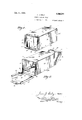
- Fig. 1 is a perspective view-0f a container [constructed in accordance with my invention,
- Fig. 2 is a perspective view of the contamer with the ends thereof open
- Fig. 3 is a perspective view of the con-.
- Fig. 4 is a blank of one section of the container, 7
- Fig. 5 is a blank of the other section of the container
- Fig. 6 is a perspective view of a slightly modified form of my container
- Fig. 7 is aperspective view of the form of container shown in Fig. 6 with the ends open,
- Fig. 8 is a longitudinal vertical section taken on lines 88 of Fig. 6,
- Fig. 9 is a blank of one section of the container shown in Fig. 6 and Fig. 10 is a blank of the other section shown in Fig. 6. a
- the container is formed of two sections, the blank 10 of which is scored at 11 to form three side panels 12.
- the blank of the other section is scored longitudinally as at 13 and transversely as at 14 to form a fourth side 15 and a pair of longitudinal flanges 16.
- This section of the blank is further scored longitudinally at 17 and transversely at 18 to form ends 19.
- the tube-like body is formed by securing the single side panel to the ends of a the section comprising the other three sides,
- the open ended tubular box may be collapsed or folded flat in compact condition 7 area. 21 adjacent each end of theside 15 for convenient storage. or shipment. When which is of the same width as the flanges Between the scores 14 and 18 there is left an 20. The areas 21 are, in effect, connecting 2 and 3, I will describe the method of assembling my improved container.
- the blank is folded along the longitudinal scores 11 until it assumes the shapeillus- -trated clearly-in Fig.2 and is then secured by stitching or otherwise to the longitudinal flanges 16 formed on the fourth side panel 15.
- the container may be passed through a stitching machine or machines, which will stitch both sides simultaneously.
- the stitching for securing the blank 10 to the side is. indicated by the referencecharacter 22.
- the container now resembles an openended tube, the ends 19 being unattached save by their integral connection with the fourth side panel 15.
- the containers may be oollapsedto a flattened or compacted condition and stored until "it becomes necessary to use them.
- Fig. 3 the container is shown in a semi-collapsed condition, the tube-like container bending at the edges formed by the longitudinal scores 11 and 13.
- the width of the strip 21 is the same as the flanges 20 so that the ends 19 fit snugly within the ends of the tube, with the outer edges of the flanges 20 extending even with the ends of the tube. In this position, the ends are secured in place by a stitching machine or the like, the stitches herein belng indicated by the reference character 23.
- one end of the box may be folded into position and stitched in place before the packing operation is commenced, access to the interior of the container being had through the other open end and when thereafter the container 1s to be closed, this end may be folded into place and stitched in the manner described before.
- This modified form of invention is capable of withstanding still greater strains and stresses because of the added strength and rigidity contributed by the flaps, 25.
- the manner of packing the container in this instance may likewise be accomplished either with both ends 19 open or with'one end-thereof closed.
- the rigidity ofthe' box is furthermore assured by the arrangement wherein a flanged end is countersunk or entirely inserted within each end of the tube-like body. Obviously before the ends are inserted the body may be collapsed by folding along the scores 11 and 13 but when'the box has been unfolded to its extended position and the flanged ends inserted the tube-like body is positively held in its unfolded or extended.
- the ends may be conveniently stitched by running ,each hollow end through the stitching machine.
- the blank 10 maybe formed a little larger and scored to provide flanges on both sides thereof correspondin to the flanges 16 formed on the fourth si e panel 15 whereby connection between the two blanks may be made.
- other obvious modifications may be resorted to without departing from the spirit and scope of my invention and to this end I reserve the right-to makesuch changes in the structure and method of assembling as may come within the purview of the accom panying claims.
- a collapsible box of-the typehaving countersunk ends comprising two attache sections of sheet material, one'section bein formed with three side panels defined by intervening scored fold lines, and the second section being formed with a fourth side panel and two integral end panels connected by foldingstrips or flanges, and short inwardly folding attaching flanges upon said fourth side panel and said end panels, all of This and various said flanges being defined by scored fold lines, I
- A'collapsible fiber shipping'case formed of two blanks one blank bein scored to form three sides, the second ⁇ flank being scored to form a fourth side with relativel short attaching flanges and two ends witi attaching flanges, said first blank being secured to the "fourth side by stitching the same to the outside of said relatively short attaching flanges, said endsbeing adapted to be bent into theopen ends of said body and secured thereto by stitching their associated flanges to said body.
- a collapsible fiber container formed in two sections, one section being scored and folded to form three sides and reinforcing flaps, the other section being scored to form said ends.
Landscapes
- Engineering & Computer Science (AREA)
- Mechanical Engineering (AREA)
- Cartons (AREA)
Description
Jan. 8 1924.
J. J. DALY FIBER SHIPPING CASE 4 Sheets-Sheet 1 Filed Feb. 7, 1922 Jan. 8 1924. 1,480,377
J. J. DALY FIBER SHIPPING CASE Filed Feb. 7 1922 4 Sheets-Sheet Z Jan. 8 1924-. 1,480,377
J.J.DALY
FIBER SHIPPING CASE Filed Feb. 1922 4 Sheets-Sheet 5 Jap. s 1924.
r 1,480,377 J. J. DALY FIBER SHIPPING CASE Filed Feb. '7, 1.922 4 Sheets-Sheet 4 Ely/0.
Jme'nicrv Patented Jan. 8, 1924.
UNITED STATES JAMES J. DALY, OF THREE RIVERS, MICHIGAN.
FIBER SHIPPING CASE.
Application filed February 7, 1922. Serial No. 534,712.
Toall whom it may concern:
Be it known that I, JAMES J. DALY, a citizen of the United States, and a resident of Three Rivers, in the county of St. Joseph sand State of Michigan, have invented certain new and useful Improvements in Fiber Shipping Cases, of which the following is a specification.
Mv invention relates to fiber shipping cases or boxes of the collapsible or knockdown type.
This invention relates particularly to im provements in boxes or shipping cases made of cardboard, strawboard, fiber or other similar material which is of such a stiff and rigid construction as to enable them to withstand the rough usage in handling and transit to which they are subjected and which will properl protect the contents packed therein.
collapsed 01' knock-down condition, so that a large supply of these containers may be kept on hand without utilizing an excessive amount of storage space. However, heretofore boxes of this general type have been 80 of such complicated construction that the cost of manufacture. owing to the difficulty in cutting and assembling has been prohibitive.
It is therefore the primary object of my invention to provide a collapsible box or v shipping case which will be strong and durable and which will comprise a. smaller number of sections or parts, this present invention illustrating a containerv formed in two parts. thus enabling thesame to be cheaply manufactured and conveniently assembled.
In carrying outmy invention. I provide one section scored so as to be folded to form three sides of the container while the other it is desired to fill the containers, the tubular body is opened or unfolded and one end panel folded into closing position and stitched in place. The container is then filled and packed and the second end folded into place and stitched. fast.
The strength and durability of the container is assured first because the number of parts to be assembled have been reduced to a minimum andsecondly, because all of the parts workon a continuous fold.
The manner of constructing andthe method of assembling my improved containers will be made more apparent in the accompanying specification and illustrated in detail in the drawings, in which:
Fig. 1 is a perspective view-0f a container [constructed in accordance with my invention,
Fig. 2 is a perspective view of the contamer with the ends thereof open,
Fig. 3 is a perspective view of the con-.
tainer partly collapsed,
Fig. 4 is a blank of one section of the container, 7
Fig. 5 is a blank of the other section of the container,
Fig. 6 is a perspective view of a slightly modified form of my container,
Fig. 7 is aperspective view of the form of container shown in Fig. 6 with the ends open,
Fig. 8 is a longitudinal vertical section taken on lines 88 of Fig. 6,
Fig. 9 is a blank of one section of the container shown in Fig. 6 and Fig. 10 is a blank of the other section shown in Fig. 6. a
Referring now more particularly to Figs. 1 to 5 the first form of my invention will be described. The container is formed of two sections, the blank 10 of which is scored at 11 to form three side panels 12. The blank of the other section is scored longitudinally as at 13 and transversely as at 14 to form a fourth side 15 and a pair of longitudinal flanges 16. This section of the blank is further scored longitudinally at 17 and transversely at 18 to form ends 19. Be-
45 section comprises the ends and one side. After the sections have been properly cut and scored. the tube-like body is formed by securing the single side panel to the ends of a the section comprising the other three sides,
' 50 the result being that of a tube, the ends cause of the shape of the blank and in con- .being left unattached, save by their integral sequence of the scoring there is provided connection with one of the side n l along three sides of each end 19 flanges 20.
The open ended tubular box may be collapsed or folded flat in compact condition 7 area. 21 adjacent each end of theside 15 for convenient storage. or shipment. When which is of the same width as the flanges Between the scores 14 and 18 there is left an 20. The areas 21 are, in effect, connecting 2 and 3, I will describe the method of assembling my improved container. The blank is folded along the longitudinal scores 11 until it assumes the shapeillus- -trated clearly-in Fig.2 and is then secured by stitching or otherwise to the longitudinal flanges 16 formed on the fourth side panel 15. In accomplishing this, the container may be passed through a stitching machine or machines, which will stitch both sides simultaneously. In the drawings the stitching for securing the blank 10 to the side is. indicated by the referencecharacter 22.
The container now resembles an openended tube, the ends 19 being unattached save by their integral connection with the fourth side panel 15. In this condition the containers may be oollapsedto a flattened or compacted condition and stored until "it becomes necessary to use them. In Fig. 3 the container is shown in a semi-collapsed condition, the tube-like container bending at the edges formed by the longitudinal scores 11 and 13.
When the containers are to be packed they are unfolded to the position illustrated in Fig. 2 whereupon they may be readily packed and the ends thereafter folded into position. In folding the ends, the flanges 20 are bent outwardly, see particularly Figs. 2 and 3, and the ends folded up along the scores 14, the areas or stops 21 disposed between the ends 19 and the side. panel 15 bending back upon the side panel 15 as clearly illustrated in Fig. 1.
As hereinbefore mentioned, the width of the strip 21 is the same as the flanges 20 so that the ends 19 fit snugly within the ends of the tube, with the outer edges of the flanges 20 extending even with the ends of the tube. In this position, the ends are secured in place by a stitching machine or the like, the stitches herein belng indicated by the reference character 23.
Obviously one end of the box may be folded into position and stitched in place before the packing operation is commenced, access to the interior of the container being had through the other open end and when thereafter the container 1s to be closed, this end may be folded into place and stitched in the manner described before.
Referring now more particularly to Figs. 6 to 10, the second formof my invention will be described This modification differs from the form of my invention previously described only in the fact that the blank 10 forming the three sides is provided with transverse scores 24, thereby forming reinforcing fiaps 25. The remaining parts of the container remain the same and hence like numerals refer to like parts.
In assembling the modified form of the over the flanges 20 as clearly illustrated in.
Figs. 6 and 8. This modified form of invention is capable of withstanding still greater strains and stresses because of the added strength and rigidity contributed by the flaps, 25. The manner of packing the container in this instance may likewise be accomplished either with both ends 19 open or with'one end-thereof closed.
The rigidity ofthe' box is furthermore assured by the arrangement wherein a flanged end is countersunk or entirely inserted within each end of the tube-like body. Obviously before the ends are inserted the body may be collapsed by folding along the scores 11 and 13 but when'the box has been unfolded to its extended position and the flanged ends inserted the tube-like body is positively held in its unfolded or extended.
condition. By forming the flanges 20 and providing the strip 21, which folds back upon the fourth side panel 15,,the ends may be conveniently stitched by running ,each hollow end through the stitching machine.
Obviously the blank 10 maybe formed a little larger and scored to provide flanges on both sides thereof correspondin to the flanges 16 formed on the fourth si e panel 15 whereby connection between the two blanks may be made. other obvious modifications may be resorted to without departing from the spirit and scope of my invention and to this end I reserve the right-to makesuch changes in the structure and method of assembling as may come within the purview of the accom panying claims.
Having thus described my invention, what I claim is 1. A collapsible box of-the typehaving countersunk ends, comprising two attache sections of sheet material, one'section bein formed with three side panels defined by intervening scored fold lines, and the second section being formed with a fourth side panel and two integral end panels connected by foldingstrips or flanges, and short inwardly folding attaching flanges upon said fourth side panel and said end panels, all of This and various said flanges being defined by scored fold lines, I
the two box sections being secured together by attaching said short side flanges of'said fourth side panel to the inner faces of the adjacent side panels of the'other box section.
2. A'collapsible fiber shipping'case formed of two blanks one blank bein scored to form three sides, the second {flank being scored to form a fourth side with relativel short attaching flanges and two ends witi attaching flanges, said first blank being secured to the "fourth side by stitching the same to the outside of said relatively short attaching flanges, said endsbeing adapted to be bent into theopen ends of said body and secured thereto by stitching their associated flanges to said body.
3. 'A collapsible fiber container forined in two sections, one section being scored and folded to form three sides, the other section being scored to form the fourth side with relatlvely short lon itudinal attaching flanges and further score to form two ends provided with attaching flanges, the three-sides 20 being secured to the fourth side along their longitudinal edges by attachment to the relatively short longitudinal attaching flanges, said attachin said side wal s, thereby forming an openended tube, said ends being adapted'to be folded into the open ends of'said tube and secured through the medium of their associated attaching flanges.
4. A collapsible fiber container formed in two sections, one section being scored and folded to form three sides and reinforcing flaps, the other section being scored to form said ends.
' JAMES J.
flanges extending between
Priority Applications (1)
| Application Number | Priority Date | Filing Date | Title |
|---|---|---|---|
| US534712A US1480377A (en) | 1922-02-07 | 1922-02-07 | Fiber shipping case |
Applications Claiming Priority (1)
| Application Number | Priority Date | Filing Date | Title |
|---|---|---|---|
| US534712A US1480377A (en) | 1922-02-07 | 1922-02-07 | Fiber shipping case |
Publications (1)
| Publication Number | Publication Date |
|---|---|
| US1480377A true US1480377A (en) | 1924-01-08 |
Family
ID=24131212
Family Applications (1)
| Application Number | Title | Priority Date | Filing Date |
|---|---|---|---|
| US534712A Expired - Lifetime US1480377A (en) | 1922-02-07 | 1922-02-07 | Fiber shipping case |
Country Status (1)
| Country | Link |
|---|---|
| US (1) | US1480377A (en) |
Cited By (11)
| Publication number | Priority date | Publication date | Assignee | Title |
|---|---|---|---|---|
| US2593834A (en) * | 1947-01-06 | 1952-04-22 | Bergstein Frank David | Transparent traylike structure |
| US2739727A (en) * | 1952-11-08 | 1956-03-27 | Fudge Robert John | Carrying containers |
| US3291370A (en) * | 1963-11-06 | 1966-12-13 | Continental Can Co | Two opposed recessed end panel carton with closure flaps |
| US3525465A (en) * | 1968-09-09 | 1970-08-25 | United States Steel Corp | Hermetic container |
| US6213643B1 (en) * | 2000-04-25 | 2001-04-10 | Chih-Ta Lin | Collapsible bag expander |
| US20080053854A1 (en) * | 2006-08-31 | 2008-03-06 | Syngenta Participations, Ag | Systems and methods for packaging trays of plantlets |
| USD590710S1 (en) * | 2008-03-27 | 2009-04-21 | Chris Mittelstaedt | Storage container |
| USD597834S1 (en) * | 2008-05-15 | 2009-08-11 | Chris Mittelstaedt | Storage container |
| USD636665S1 (en) * | 2008-03-27 | 2011-04-26 | Chris Mittelstaedt | Storage container |
| USD740026S1 (en) * | 2014-02-06 | 2015-10-06 | Shinwa Co., Ltd. | Storage case |
| EP3388354A1 (en) * | 2017-04-13 | 2018-10-17 | DS Smith Plc | Box made of two belts, blank, set of belts, methods of forming the same, method and machine for packaging products in a box |
-
1922
- 1922-02-07 US US534712A patent/US1480377A/en not_active Expired - Lifetime
Cited By (11)
| Publication number | Priority date | Publication date | Assignee | Title |
|---|---|---|---|---|
| US2593834A (en) * | 1947-01-06 | 1952-04-22 | Bergstein Frank David | Transparent traylike structure |
| US2739727A (en) * | 1952-11-08 | 1956-03-27 | Fudge Robert John | Carrying containers |
| US3291370A (en) * | 1963-11-06 | 1966-12-13 | Continental Can Co | Two opposed recessed end panel carton with closure flaps |
| US3525465A (en) * | 1968-09-09 | 1970-08-25 | United States Steel Corp | Hermetic container |
| US6213643B1 (en) * | 2000-04-25 | 2001-04-10 | Chih-Ta Lin | Collapsible bag expander |
| US20080053854A1 (en) * | 2006-08-31 | 2008-03-06 | Syngenta Participations, Ag | Systems and methods for packaging trays of plantlets |
| USD590710S1 (en) * | 2008-03-27 | 2009-04-21 | Chris Mittelstaedt | Storage container |
| USD636665S1 (en) * | 2008-03-27 | 2011-04-26 | Chris Mittelstaedt | Storage container |
| USD597834S1 (en) * | 2008-05-15 | 2009-08-11 | Chris Mittelstaedt | Storage container |
| USD740026S1 (en) * | 2014-02-06 | 2015-10-06 | Shinwa Co., Ltd. | Storage case |
| EP3388354A1 (en) * | 2017-04-13 | 2018-10-17 | DS Smith Plc | Box made of two belts, blank, set of belts, methods of forming the same, method and machine for packaging products in a box |
Similar Documents
| Publication | Publication Date | Title |
|---|---|---|
| US1623107A (en) | Gasoline receptacle | |
| US2416816A (en) | Bag | |
| US2226178A (en) | Container | |
| US1480377A (en) | Fiber shipping case | |
| US1151821A (en) | Carton. | |
| US3194472A (en) | Shipping container | |
| USRE21158E (en) | Collapsible caeton | |
| US2044103A (en) | Knock-down end closing carton | |
| US1522311A (en) | Carton | |
| US1718872A (en) | Collapsible box | |
| US2326281A (en) | Box construction | |
| US1081068A (en) | Folding paper box. | |
| US1145668A (en) | Knockdown box. | |
| US2157392A (en) | Bag | |
| US2229425A (en) | Container | |
| US2074229A (en) | Collapsible container | |
| US2113481A (en) | Paper receptacle | |
| US2551164A (en) | Reinforced knockdown box | |
| US2175476A (en) | Shipping carton | |
| US2361937A (en) | Box | |
| US3148821A (en) | Collapsible and reusable container | |
| US1783068A (en) | Folding container | |
| US1722422A (en) | Carton and its blank | |
| US1787499A (en) | Collapsible display container | |
| US1718204A (en) | Folding box |