US11987042B2 - Method and apparatus for printing radiopaque indicia - Google Patents
Method and apparatus for printing radiopaque indicia Download PDFInfo
- Publication number
- US11987042B2 US11987042B2 US17/181,496 US202117181496A US11987042B2 US 11987042 B2 US11987042 B2 US 11987042B2 US 202117181496 A US202117181496 A US 202117181496A US 11987042 B2 US11987042 B2 US 11987042B2
- Authority
- US
- United States
- Prior art keywords
- marking fluid
- radiopaque marking
- etchings
- access port
- venous access
- Prior art date
- Legal status (The legal status is an assumption and is not a legal conclusion. Google has not performed a legal analysis and makes no representation as to the accuracy of the status listed.)
- Active, expires
Links
- 238000007639 printing Methods 0.000 title abstract description 44
- 238000000034 method Methods 0.000 title abstract description 17
- 239000012530 fluid Substances 0.000 claims abstract description 90
- 238000005530 etching Methods 0.000 claims abstract description 39
- WFKWXMTUELFFGS-UHFFFAOYSA-N tungsten Chemical compound [W] WFKWXMTUELFFGS-UHFFFAOYSA-N 0.000 claims abstract description 16
- 229910052721 tungsten Inorganic materials 0.000 claims abstract description 16
- 239000010937 tungsten Substances 0.000 claims abstract description 16
- 238000002347 injection Methods 0.000 claims description 16
- 239000007924 injection Substances 0.000 claims description 16
- 239000000463 material Substances 0.000 claims description 9
- 238000012546 transfer Methods 0.000 claims description 5
- 238000007664 blowing Methods 0.000 claims description 4
- 229920001296 polysiloxane Polymers 0.000 claims description 3
- 238000012545 processing Methods 0.000 claims description 2
- 239000000126 substance Substances 0.000 claims description 2
- 238000011179 visual inspection Methods 0.000 claims description 2
- 239000003570 air Substances 0.000 claims 6
- 239000012080 ambient air Substances 0.000 claims 1
- 238000000151 deposition Methods 0.000 claims 1
- 238000002591 computed tomography Methods 0.000 description 16
- 230000000712 assembly Effects 0.000 description 9
- 238000000429 assembly Methods 0.000 description 9
- 239000002872 contrast media Substances 0.000 description 8
- 239000000758 substrate Substances 0.000 description 8
- 229940039231 contrast media Drugs 0.000 description 7
- 229910052751 metal Inorganic materials 0.000 description 5
- 239000002184 metal Substances 0.000 description 5
- 230000002792 vascular Effects 0.000 description 5
- 238000003384 imaging method Methods 0.000 description 4
- 238000001802 infusion Methods 0.000 description 4
- 230000000747 cardiac effect Effects 0.000 description 3
- 238000004140 cleaning Methods 0.000 description 3
- 238000010968 computed tomography angiography Methods 0.000 description 3
- 238000005516 engineering process Methods 0.000 description 3
- 238000001990 intravenous administration Methods 0.000 description 3
- 229920002492 poly(sulfone) Polymers 0.000 description 3
- 210000001367 artery Anatomy 0.000 description 2
- 230000008901 benefit Effects 0.000 description 2
- 230000003111 delayed effect Effects 0.000 description 2
- 238000002513 implantation Methods 0.000 description 2
- 239000000203 mixture Substances 0.000 description 2
- 238000012986 modification Methods 0.000 description 2
- 230000004048 modification Effects 0.000 description 2
- 210000003462 vein Anatomy 0.000 description 2
- 150000001875 compounds Chemical class 0.000 description 1
- 230000006835 compression Effects 0.000 description 1
- 238000007906 compression Methods 0.000 description 1
- 238000005336 cracking Methods 0.000 description 1
- 238000001035 drying Methods 0.000 description 1
- 230000000694 effects Effects 0.000 description 1
- 238000011156 evaluation Methods 0.000 description 1
- 238000007789 sealing Methods 0.000 description 1
- 229920002379 silicone rubber Polymers 0.000 description 1
- 239000002904 solvent Substances 0.000 description 1
- 238000013519 translation Methods 0.000 description 1
Images


Classifications
-
- B—PERFORMING OPERATIONS; TRANSPORTING
- B41—PRINTING; LINING MACHINES; TYPEWRITERS; STAMPS
- B41F—PRINTING MACHINES OR PRESSES
- B41F17/00—Printing apparatus or machines of special types or for particular purposes, not otherwise provided for
- B41F17/001—Pad printing apparatus or machines
-
- A—HUMAN NECESSITIES
- A61—MEDICAL OR VETERINARY SCIENCE; HYGIENE
- A61M—DEVICES FOR INTRODUCING MEDIA INTO, OR ONTO, THE BODY; DEVICES FOR TRANSDUCING BODY MEDIA OR FOR TAKING MEDIA FROM THE BODY; DEVICES FOR PRODUCING OR ENDING SLEEP OR STUPOR
- A61M39/00—Tubes, tube connectors, tube couplings, valves, access sites or the like, specially adapted for medical use
- A61M39/02—Access sites
- A61M39/0208—Subcutaneous access sites for injecting or removing fluids
-
- C—CHEMISTRY; METALLURGY
- C09—DYES; PAINTS; POLISHES; NATURAL RESINS; ADHESIVES; COMPOSITIONS NOT OTHERWISE PROVIDED FOR; APPLICATIONS OF MATERIALS NOT OTHERWISE PROVIDED FOR
- C09D—COATING COMPOSITIONS, e.g. PAINTS, VARNISHES OR LACQUERS; FILLING PASTES; CHEMICAL PAINT OR INK REMOVERS; INKS; CORRECTING FLUIDS; WOODSTAINS; PASTES OR SOLIDS FOR COLOURING OR PRINTING; USE OF MATERIALS THEREFOR
- C09D11/00—Inks
- C09D11/02—Printing inks
-
- A—HUMAN NECESSITIES
- A61—MEDICAL OR VETERINARY SCIENCE; HYGIENE
- A61M—DEVICES FOR INTRODUCING MEDIA INTO, OR ONTO, THE BODY; DEVICES FOR TRANSDUCING BODY MEDIA OR FOR TAKING MEDIA FROM THE BODY; DEVICES FOR PRODUCING OR ENDING SLEEP OR STUPOR
- A61M39/00—Tubes, tube connectors, tube couplings, valves, access sites or the like, specially adapted for medical use
- A61M39/02—Access sites
- A61M39/0208—Subcutaneous access sites for injecting or removing fluids
- A61M2039/0238—Subcutaneous access sites for injecting or removing fluids having means for locating the implanted device to insure proper injection, e.g. radio-emitter, protuberances, radio-opaque markers
-
- B—PERFORMING OPERATIONS; TRANSPORTING
- B41—PRINTING; LINING MACHINES; TYPEWRITERS; STAMPS
- B41M—PRINTING, DUPLICATING, MARKING, OR COPYING PROCESSES; COLOUR PRINTING
- B41M1/00—Inking and printing with a printer's forme
- B41M1/10—Intaglio printing ; Gravure printing
-
- B—PERFORMING OPERATIONS; TRANSPORTING
- B41—PRINTING; LINING MACHINES; TYPEWRITERS; STAMPS
- B41M—PRINTING, DUPLICATING, MARKING, OR COPYING PROCESSES; COLOUR PRINTING
- B41M1/00—Inking and printing with a printer's forme
- B41M1/22—Metallic printing; Printing with powdered inks
-
- B—PERFORMING OPERATIONS; TRANSPORTING
- B41—PRINTING; LINING MACHINES; TYPEWRITERS; STAMPS
- B41M—PRINTING, DUPLICATING, MARKING, OR COPYING PROCESSES; COLOUR PRINTING
- B41M7/00—After-treatment of prints, e.g. heating, irradiating, setting of the ink, protection of the printed stock
-
- B—PERFORMING OPERATIONS; TRANSPORTING
- B41—PRINTING; LINING MACHINES; TYPEWRITERS; STAMPS
- B41M—PRINTING, DUPLICATING, MARKING, OR COPYING PROCESSES; COLOUR PRINTING
- B41M7/00—After-treatment of prints, e.g. heating, irradiating, setting of the ink, protection of the printed stock
- B41M7/009—After-treatment of prints, e.g. heating, irradiating, setting of the ink, protection of the printed stock using thermal means, e.g. infrared radiation, heat
Definitions
- This invention relates to a method and apparatus for printing radiopaque indicia on a medical device and, more specifically, to a method and apparatus for printing radiopaque marking fluid onto a venous access port.
- Venous access ports for the infusion and/or withdrawal of fluids from a patient are known in the art.
- Such ports generally comprise a needle-penetrable septum, a cap, and a port housing comprising a fluid reservoir.
- the needle-penetrable septum is disposed on the port housing to seal the fluid reservoir.
- the cap secures the septum to the port housing.
- Such ports additionally include a discharge port comprising a fluid passageway that communicates with the fluid reservoir and a catheter secured to the discharge port.
- a method of printing radiopaque indicia on a medical device includes applying radiopaque marking fluid to a surface of a plate comprising one or more etchings having a depth of at least 0.0001 inches, exposing the radiopaque marking fluid on the surface of the plate to air to allow the radiopaque marking fluid to achieve a sufficient level of tackiness, and transferring the radiopaque marking fluid to a medical device.
- the radiopaque marking fluid comprises a clear ink and tungsten particulates having a particulate size of more than one micron.
- a printing apparatus for printing radiopaque indicia on a medical device.
- the printing apparatus includes a plate comprising one or more etchings having a depth of at least 0.0001 inches, a cup containing a radiopaque marking fluid, a jig for holding a medical device, and a pad for transferring radiopaque marking fluid deposited within the one or more etchings to the medical device.
- the radiopaque marking fluid comprises a clear ink and tungsten particulates having a particulate size of more than one micron.
- the cup is configured to be inverted and pressed against the plate to effect a fluid seal of the radiopaque marking fluid against the plate.
- FIG. 1 A illustrates an exemplary printing apparatus comprising a cup, a plate, and a pad, wherein the printing apparatus in an idle state (first position) in which the cup is disposed over etchings in the plate, in accordance with an exemplary embodiment of the present invention
- FIG. 1 B illustrates the exemplary printing apparatus in a second position in which the cup has been translated off the etchings in the plate, in accordance with an exemplary embodiment of the present invention
- FIG. 2 illustrates the plate of the exemplary printing apparatus, in accordance with an exemplary embodiment of the present invention
- FIG. 3 illustrates the cup of the exemplary printing apparatus, in accordance with an exemplary embodiment of the present invention
- FIG. 4 illustrates an exemplary venous access port assembly, in accordance with an exemplary embodiment of the present invention
- FIG. 5 A is a planar view of the bottom of an exemplary venous access port assembly onto which radiopaque indicia have been printed using the exemplary printing apparatus illustrated in FIG. 1 , in accordance with an exemplary embodiment of the present invention.
- FIG. 5 B is an isometric view of the exemplary venous access port assembly of FIG. 5 A , in accordance with an exemplary embodiment of the present invention.
- the printing apparatus 100 comprises a bed 110 for supporting a plate 200 and a bed 130 for supporting a jig 140 that holds a medical device (not illustrated in FIG. 1 A ) onto which the exemplary printing apparatus 100 prints indicia.
- a metal plate 115 onto which the plate 200 is secured.
- the metal plate 115 is pinned to the bed 110 , and the plate 200 is held in place with dowel pins on the metal plate 115 .
- the jig 140 includes bolt holes 143 and 144 through which bolts secure the jig 140 to the bed 130 .
- the jig 140 also includes recess 141 and 142 into which medical devices are disposed.
- the recesses 141 and 142 hold the medical devices in place while the printing apparatus 100 prints indicia onto the medical devices.
- a venous access port assembly is disposed into each of the recesses 141 and 142 , with a bottom surface of each access port assembly facing upwards away from the top face of the jig 140 .
- the printing apparatus 100 additionally comprises a cup 300 attached to an arm 120 . Attached to the bottom of the cup 300 is a ring 350 .
- the cup 300 contains ink that is applied to a top surface 210 of the plate 200 .
- the printing apparatus 100 also comprises a pad 150 for transferring the ink on the top surface 210 of the plate 200 to the medical devices in the jig 140 .
- FIG. 1 A illustrates an idle state of the printing apparatus 100 in which the cup 300 is in a first position atop the plate 200 .
- FIG. 1 B there is illustrated a second position of the cup 300 , in accordance with an exemplary embodiment of the present invention. As is illustrated in FIG. 1 B , in the second position, the cup 300 is disposed at an end of the plate 200 away from the jig 140 . In the second position of the cup 300 , etchings 220 and 230 on the top surface 210 of the plate 200 are exposed.
- FIG. 2 there is illustrated a closer view of the top surface 210 of the plate 200 , in accordance with an exemplary embodiment of the present invention.
- the etchings 220 and 230 in the top surface 210 of the plate 200 comprise the letters “CT.”
- the exemplary plate 200 is used to print “CT” onto the medical devices, e.g., venous access port assemblies, held by the jig 140 .
- the exemplary printing apparatus 100 prints a radiopaque marking fluid onto the medical devices held in the jig 140 .
- An exemplary radiopaque marking fluid comprises a mixture of a clear ink and tungsten particulates in a defined ratio.
- the ratio depends upon the substrate, i.e., the material of the medical devices in the jig 140 , on which the radiopaque marking fluid is to be applied.
- the ratio depends on the substrate material, the durometer of the substrate, the chemical makeup (compound) of the substrate or the material (substrate) receiving the indicia, and/or processing of the material receiving the indicia.
- the ratio of the mixture is suitable for application to a polysulfone substrate, such as a venous access port assembly formed from polysulfone.
- a polysulfone substrate such as a venous access port assembly formed from polysulfone.
- Flexible substrates use a radiopaque marking fluid having a clear ink/tungsten ratio that results in the indicia printed onto the medical devices being flexible also to prevent cracking.
- Stiff substrates allow a clear ink/tungsten ratio that results in stiff indicia printed onto the medical device.
- Each of the etchings 220 and 230 have respective depths to accommodate ink applied by the cup 300 .
- the depths of the etchings 220 and 230 may be between 0.0001 inch (0.000254 cm) and 0.003 inch (0.00762 cm). The depths depend upon the size of the tungsten particulates in the radiopaque marking fluid. Generally speaking, the depths of the etchings 220 and 230 must be increased to accommodate larger tungsten particulates in the radiopaque marking fluid.
- Radiopacity of the radiopaque marking fluid varies inversely with the size of the tungsten particulates in the radiopaque marking fluid. Smaller particulates have a lower radiopacity than larger particulates.
- the exemplary printing apparatus 100 desirably performs more hits (applications of radiopaque marking fluid) on the subject medical device to transfer the shape or letters defined by the etchings 220 and 230 onto the medical device, as compared to a lower number of hits required for a radiopaque marking fluid having relatively larger tungsten particulates.
- Desirable sizes of the tungsten particulates are on the order of one to several microns. In an exemplary embodiment, the size of the tungsten particulates is from one to five microns.
- the medical devices should be cleaned using a suitable cleaning means.
- suitable cleaning means include plasma, solvent, aqueous, etc.
- the cleaning means are not limited to any one technology.
- Other specifications of the printing apparatus 100 include the material forming the pad 150 , the time for which the radiopaque marking fluid applied in the etchings 220 and 230 are exposed to air before being transferred by the pad 150 to the medical devices, and flash-off time for the radiopaque marking fluid.
- the firmness of the pad 150 is selected in order to facilitate the transfer of as much radiopaque marking fluid within the etchings 220 and 230 to the medical devices that will adhere to the devices.
- the pad 150 is formed from silicone.
- the flash-off time of the radiopaque marking fluid is selected so that the radiopaque marking fluid achieves a desired level of tackiness while it is exposed to air before being transferred to the medical devices.
- Such exposure to air may include blowing chilled air, heated air, or air at room temperature onto the radiopaque marking fluid within the etchings 220 and 230 .
- the temperature and humidity of the air applied to the radiopaque marking fluid within the etchings 220 and 230 is selected to achieve the desired level of tackiness of the radiopaque marking fluid before being transferred to the medical devices.
- the cup 300 comprises an outer rim 305 and an inner riser 310 . Together, the outer rim 305 and inner riser 310 define an interior cavity 330 which contains the ink or radiopaque marking fluid used in the printing process.
- the ring 350 is secured to the rim 305 of the cup 300 .
- the ring 350 performs several duties. It seals the ink within the cup 300 , specifically within the interior cavity 330 of the cup 300 , when the cup 300 is disposed on the plate 200 . Further, it acts as a squeegee to wipe ink off the top surface 210 of the plate 200 during the printing process.
- the magnets 320 are attracted to the plate 200 to allow the ring 350 to perform its sealing and wiping functions. Because the magnets 320 are attracted to the plate 200 , the cup 300 compresses the ring 350 against the plate 200 and presses the plate 200 against the metal plate 115 .
- a technician places venous access port assemblies into the recesses 141 and 142 of the jig 140 and attaches the plate 200 to the metal plate 115 .
- the technician fills the cavity 330 of the cup with a radiopaque marking fluid that will be applied to the venous access port assemblies within the recesses 141 and 142 and subsequent venous access port assemblies that will be placed within the recesses 141 and 142 in subsequent printing operations.
- the technician then places the printing apparatus 100 in the idle state in which the cup 300 is disposed on the top surface 210 of the plate 200 over the etchings 220 and 230 .
- the radiopaque marking fluid within the cup 300 covers and fills the etchings 220 and 230 and covers the portion of the top surface 210 over which the cup 300 is disposed.
- the technician then commands the printing apparatus 100 to transfer the radiopaque marking fluid from the etchings 220 and 230 to the medical devices, i.e., to perform a “hit.”
- the printing apparatus 100 translates the cup 300 away from the etchings 220 and 230 .
- the ring 350 secured to the bottom of the cup 300 acts as a squeegee to wipe any radiopaque marking fluid on the top surface 210 of the plate 200 outside of the etchings 220 and 230 .
- the cup 300 moves to the second position, and radiopaque marking fluid remains within the etchings 220 and 230 .
- the radiopaque marking fluid within the etchings 220 and 230 is then exposed to air to achieve a desired tackiness. Such air may be at room temperature or heated or chilled.
- air may be at room temperature or heated or chilled.
- the pad 150 hits the etchings 220 and 230 and picks up some or all of the radiopaque marking fluid within the etchings 220 and 230 .
- the pad 150 then hits the medical devices within the recesses 141 and 142 to transfer the radiopaque marking fluid to the medical devices.
- the printing apparatus 100 returns to its idle state.
- the printing apparatus 100 repeats the process described above to perform additional hits on the medical devices to layer the radiopaque marking fluid on the medical devices to achieve a desired level of radiopacity of the printed indicia.
- the medical devices are removed from the jig, and new medical devices are inserted to be printed using the process described above.
- the deposited radiopaque marking fluid may be allowed to air dry, or the printed medical devices may be placed into an oven to speed the drying process.
- the venous access port assembly 400 comprises a septum 410 and a housing 420 that includes an interior fluid reservoir (not illustrated).
- the septum 410 is disposed on the port housing 420 to seal the interior fluid reservoir.
- the venous access port assembly 400 additionally comprises a discharge port 430 extending from a distal end 440 of the port assembly 400 .
- the discharge port 430 is attached securely and sealingly to the proximal end of a catheter (not illustrated).
- a passageway extends from the interior reservoir to a distal tip opening 450 of discharge port 430 .
- the port assembly further comprises a cap 460 which secures the septum 410 to the port housing 420 to maintain the fluid seal within the interior fluid reservoir.
- the recesses 141 and 142 formed within the jig 140 are shaped to hold the access port assembly 400 during the printing process.
- an access port assembly 400 is disposed within each of the recesses 141 and 142 such that the septum 410 of each port assembly 400 faces down and a bottom surface of each port assembly 400 face up toward the pad 150 .
- the printing apparatus 100 applies ink to the bottom surface of each port assembly 400 .
- the printing apparatus 100 applies radiopaque marking fluid to the bottom surface of each port assembly 400 .
- the venous access port assembly 400 is further described in U.S. patent application Ser. No. 11/801,050 filed May 7, 2007 and claiming priority from U.S. Provisional Patent Application Ser. No. 60/801,523 filed May 18, 2006 and in U.S. patent application Ser. No. 12/143,377 filed Jun. 20, 2008 and claiming priority from U.S. Provisional Patent Application Ser. No. 60/936,491 filed Jun. 20, 2007, the contents of all of which applications are hereby incorporated by reference in their entirety for all purposes.
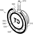
- FIG. 5 A illustrates a planar view of a port assembly 500 onto which indicia have been printed, in accordance with an exemplary embodiment of the present invention.
- FIG. 5 B illustrates an isometric view of the port assembly 500 , in accordance with an exemplary embodiment of the present invention.
- the port assembly 500 comprises a base 510 having a bottom surface 520 onto which indicia have been printed.
- the indicia include indicia 530 centered on the bottom surface 520 of the port assembly 500 .
- indicia 530 comprise the letters “CT” representing the term “computed tomography.” The meaning of this term is described in further detail below.
- the indicia on the bottom surface 520 further include a smaller inner circle 540 and a larger outer circle 550 provided on the outermost periphery of bottom surface 520 .
- the outer circle 550 includes a gap 560 where the port assembly 500 includes a recess to accommodate a stem 570 .
- the printing apparatus 100 applies radiopaque marking fluid to print radiopaque indicia onto the medical devices disposed within the recesses 141 and 142 of the jig.
- the medical devices may be formed from radiotransparent material.
- the printing apparatus 100 prints radiopaque indicia on venous access port assemblies, such as the port assemblies 400 or 500 .
- the port assemblies 400 and 500 are formed from a plastic material, such as a silicone elastomer or polysulfone.
- the indicia 530 , the inner circle 540 , and the outer circle 550 are printed with radiopaque marking fluid.
- CT computed tomography
- MDCT Multidetector computed tomography
- intravenous contrast media injection protocols are coordinated and selected for the anatomic area of interest.
- a so-called “power injector” system may be employed for injecting contrast media at a high pressure into a peripherally inserted intravenous (IV) line.
- IV intravenous
- Such power injection systems are, in general, controllable by selecting a desired flow rate. Accordingly, such power injection systems may develop pressure (within the maximum pressure capability of the power injection system) as is necessary to maintain the selected flow rate.
- the pressure required for contrast injection depends on many factors, including flow rate, contrast viscosity, configuration of infusion tubing, such as tube diameter and length, and any obstruction or restriction to flow (e.g., kinks, curves, fittings, compression).
- a power injector may generate high pressures. Ruptures can occur when the injection pressure exceeds the tolerance of the vascular access devices, such as venous access ports. Other problems may occur due to timing errors between the scan and the contrast.
- the starting of the scanning process can be delayed a predetermined amount of time after injection of the contrast media has begun.
- arteries can appear smaller than they really are when the image is post-processed.
- image artifacts can arise from diluted contrast in the cardiac veins.
- the window of opportunity for optimal scans may be very small, because contrast media circulates quickly through cardiac arteries and into cardiac veins.
- high pressure injection is understood to mean injections in which pressures within the port assembly 400 or 500 reach pressures generated by power injections having fluid flow rates between about 1 milliliter per second and about 5 milliliters per second. Such pressures may be between about 37 psi (255 kPa) to about 65 psi (448 kPa) within the reservoir of such port assemblies.
- the radiopaque indicia such as the indicia 530 , 540 , and 550 , indicate that the medical device, e.g., the port assembly 500 , on which such indicia are printed by the printing apparatus 100 , is rated for high pressure injection such as is necessary for infusion into a patient of contrast medium that is used in computed tomography.
- the indicia 530 comprise the letters “CT.”
- Other indicia may be used that indicate some other attribute or characteristic of the venous access port assembly.
- a clinician By printing radiopaque indicia onto a venous access port assembly rated for high pressure injections, a clinician is able to verify that such venous access port assembly is rated for high pressure injections after being implanted into a patient. Specifically, such clinician may X-ray the implanted port assembly and be able to verify that such port assembly is rated for high pressure injection if “CT” is discernable on the port assembly in the X-ray image. Further, because the radiopaque marking fluid is applied to an exterior surface of the venous access port assembly, the indicia (e.g., “CT”) are viewable to the naked eye prior to implantation. Thus, the surgeon implanting the port assembly is able to verify that such port assembly is rated for high pressure injection by visual inspection of the port assembly prior to implantation. In an exemplary embodiment, the CT indicia appear to be black to the naked eye.
Landscapes
- Chemical & Material Sciences (AREA)
- Engineering & Computer Science (AREA)
- Health & Medical Sciences (AREA)
- Life Sciences & Earth Sciences (AREA)
- Heart & Thoracic Surgery (AREA)
- Organic Chemistry (AREA)
- Wood Science & Technology (AREA)
- Materials Engineering (AREA)
- Biomedical Technology (AREA)
- General Health & Medical Sciences (AREA)
- Public Health (AREA)
- Veterinary Medicine (AREA)
- Animal Behavior & Ethology (AREA)
- Hematology (AREA)
- Anesthesiology (AREA)
- Pulmonology (AREA)
- Media Introduction/Drainage Providing Device (AREA)
- Infusion, Injection, And Reservoir Apparatuses (AREA)
- Materials For Medical Uses (AREA)
- ing And Chemical Polishing (AREA)
Abstract
A method of printing radiopaque indicia on a medical device. The method includes applying radiopaque marking fluid to a surface of a plate comprising one or more etchings having a depth of at least 0.0001 inches, exposing the radiopaque marking fluid on the surface of the plate to air to allow the radiopaque marking fluid to achieve a sufficient level of tackiness, and transferring the radiopaque marking fluid to a medical device. The radiopaque marking fluid comprises a clear ink and tungsten particulates having a particulate size of more than one micron.
Description
This application is a continuation of application Ser. No. 13/101,878, filed May 5, 2011, which claims the benefit of U.S. provisional application Ser. No. 61/331,671, filed May 5, 2010. The disclosures of which are hereby incorporated by reference in their entirety.
This invention relates to a method and apparatus for printing radiopaque indicia on a medical device and, more specifically, to a method and apparatus for printing radiopaque marking fluid onto a venous access port.
Venous access ports for the infusion and/or withdrawal of fluids from a patient are known in the art. Such ports generally comprise a needle-penetrable septum, a cap, and a port housing comprising a fluid reservoir. The needle-penetrable septum is disposed on the port housing to seal the fluid reservoir. The cap secures the septum to the port housing. Such ports additionally include a discharge port comprising a fluid passageway that communicates with the fluid reservoir and a catheter secured to the discharge port.
It is desired to provide a venous access port assembly that provides a medical practitioner with capability to discern an important property of the port assembly after the port assembly has been implanted into a patient.
In accordance with an exemplary aspect of the present invention, there is provided a method of printing radiopaque indicia on a medical device. The method includes applying radiopaque marking fluid to a surface of a plate comprising one or more etchings having a depth of at least 0.0001 inches, exposing the radiopaque marking fluid on the surface of the plate to air to allow the radiopaque marking fluid to achieve a sufficient level of tackiness, and transferring the radiopaque marking fluid to a medical device. The radiopaque marking fluid comprises a clear ink and tungsten particulates having a particulate size of more than one micron.
In accordance with a further exemplary aspect of the present invention, there is provided a printing apparatus for printing radiopaque indicia on a medical device. The printing apparatus includes a plate comprising one or more etchings having a depth of at least 0.0001 inches, a cup containing a radiopaque marking fluid, a jig for holding a medical device, and a pad for transferring radiopaque marking fluid deposited within the one or more etchings to the medical device. The radiopaque marking fluid comprises a clear ink and tungsten particulates having a particulate size of more than one micron. The cup is configured to be inverted and pressed against the plate to effect a fluid seal of the radiopaque marking fluid against the plate.
For the purpose of illustration, there are shown in the drawings certain exemplary embodiments of the present invention. In the drawings, like numerals indicate like elements throughout. It should be understood, however, that the invention is not limited to the precise arrangements, dimensions, and instruments shown. In the drawings are included the following figures:
Referring now to FIG. 1A , there is illustrated an exemplary printing apparatus, generally designated as 100, in accordance with an exemplary embodiment of the present invention. The printing apparatus 100 comprises a bed 110 for supporting a plate 200 and a bed 130 for supporting a jig 140 that holds a medical device (not illustrated in FIG. 1A ) onto which the exemplary printing apparatus 100 prints indicia.
Mounted onto the bed 110 is a metal plate 115 onto which the plate 200 is secured. In an exemplary embodiment, the metal plate 115 is pinned to the bed 110, and the plate 200 is held in place with dowel pins on the metal plate 115.
The jig 140 includes bolt holes 143 and 144 through which bolts secure the jig 140 to the bed 130. The jig 140 also includes recess 141 and 142 into which medical devices are disposed. The recesses 141 and 142 hold the medical devices in place while the printing apparatus 100 prints indicia onto the medical devices. In an exemplary embodiment, a venous access port assembly is disposed into each of the recesses 141 and 142, with a bottom surface of each access port assembly facing upwards away from the top face of the jig 140.
The printing apparatus 100 additionally comprises a cup 300 attached to an arm 120. Attached to the bottom of the cup 300 is a ring 350. The cup 300 contains ink that is applied to a top surface 210 of the plate 200. The printing apparatus 100 also comprises a pad 150 for transferring the ink on the top surface 210 of the plate 200 to the medical devices in the jig 140.
Referring now to FIG. 2 , there is illustrated a closer view of the top surface 210 of the plate 200, in accordance with an exemplary embodiment of the present invention. As can be seen in FIG. 2 , the etchings 220 and 230 in the top surface 210 of the plate 200 comprise the letters “CT.” The exemplary plate 200 is used to print “CT” onto the medical devices, e.g., venous access port assemblies, held by the jig 140.
In an exemplary embodiment, the exemplary printing apparatus 100 prints a radiopaque marking fluid onto the medical devices held in the jig 140. An exemplary radiopaque marking fluid comprises a mixture of a clear ink and tungsten particulates in a defined ratio. Generally, the ratio depends upon the substrate, i.e., the material of the medical devices in the jig 140, on which the radiopaque marking fluid is to be applied. Thus, the ratio depends on the substrate material, the durometer of the substrate, the chemical makeup (compound) of the substrate or the material (substrate) receiving the indicia, and/or processing of the material receiving the indicia. In an exemplary embodiment, the ratio of the mixture is suitable for application to a polysulfone substrate, such as a venous access port assembly formed from polysulfone. Flexible substrates use a radiopaque marking fluid having a clear ink/tungsten ratio that results in the indicia printed onto the medical devices being flexible also to prevent cracking. Stiff substrates allow a clear ink/tungsten ratio that results in stiff indicia printed onto the medical device.
Each of the etchings 220 and 230 have respective depths to accommodate ink applied by the cup 300. In the embodiment in which the exemplary printing apparatus 100 applies radiopaque marking fluid to a medical device, the depths of the etchings 220 and 230 may be between 0.0001 inch (0.000254 cm) and 0.003 inch (0.00762 cm). The depths depend upon the size of the tungsten particulates in the radiopaque marking fluid. Generally speaking, the depths of the etchings 220 and 230 must be increased to accommodate larger tungsten particulates in the radiopaque marking fluid.
Radiopacity of the radiopaque marking fluid varies inversely with the size of the tungsten particulates in the radiopaque marking fluid. Smaller particulates have a lower radiopacity than larger particulates. Thus, when using a radiopaque marking fluid having relatively smaller tungsten particulates, the exemplary printing apparatus 100 desirably performs more hits (applications of radiopaque marking fluid) on the subject medical device to transfer the shape or letters defined by the etchings 220 and 230 onto the medical device, as compared to a lower number of hits required for a radiopaque marking fluid having relatively larger tungsten particulates. Desirable sizes of the tungsten particulates are on the order of one to several microns. In an exemplary embodiment, the size of the tungsten particulates is from one to five microns.
To ensure proper adhesion of the radiopaque marking fluid to the medical devices within the recesses 141 and 142, the medical devices should be cleaned using a suitable cleaning means. Examples of suitable cleaning means include plasma, solvent, aqueous, etc. The cleaning means are not limited to any one technology.
Other specifications of the printing apparatus 100 include the material forming the pad 150, the time for which the radiopaque marking fluid applied in the etchings 220 and 230 are exposed to air before being transferred by the pad 150 to the medical devices, and flash-off time for the radiopaque marking fluid. The firmness of the pad 150 is selected in order to facilitate the transfer of as much radiopaque marking fluid within the etchings 220 and 230 to the medical devices that will adhere to the devices. In a further exemplary embodiment of the printing apparatus 100, the pad 150 is formed from silicone.
The flash-off time of the radiopaque marking fluid is selected so that the radiopaque marking fluid achieves a desired level of tackiness while it is exposed to air before being transferred to the medical devices. Such exposure to air may include blowing chilled air, heated air, or air at room temperature onto the radiopaque marking fluid within the etchings 220 and 230. The temperature and humidity of the air applied to the radiopaque marking fluid within the etchings 220 and 230 is selected to achieve the desired level of tackiness of the radiopaque marking fluid before being transferred to the medical devices.
Referring now to FIG. 3 , there is illustrated a view of the underside of the cup 300 and the ring 350, in accordance with an exemplary embodiment of the present invention. The cup 300 comprises an outer rim 305 and an inner riser 310. Together, the outer rim 305 and inner riser 310 define an interior cavity 330 which contains the ink or radiopaque marking fluid used in the printing process. The ring 350 is secured to the rim 305 of the cup 300. The ring 350 performs several duties. It seals the ink within the cup 300, specifically within the interior cavity 330 of the cup 300, when the cup 300 is disposed on the plate 200. Further, it acts as a squeegee to wipe ink off the top surface 210 of the plate 200 during the printing process.
Disposed on the riser 310 is a plurality of magnets 320. The magnets 320 are attracted to the plate 200 to allow the ring 350 to perform its sealing and wiping functions. Because the magnets 320 are attracted to the plate 200, the cup 300 compresses the ring 350 against the plate 200 and presses the plate 200 against the metal plate 115.
An exemplary method of printing radiopaque marking fluid onto a bottom surface of venous access port assemblies is now described with reference to FIGS. 1A, 1B, 2, and 3 . A technician places venous access port assemblies into the recesses 141 and 142 of the jig 140 and attaches the plate 200 to the metal plate 115. The technician fills the cavity 330 of the cup with a radiopaque marking fluid that will be applied to the venous access port assemblies within the recesses 141 and 142 and subsequent venous access port assemblies that will be placed within the recesses 141 and 142 in subsequent printing operations. The technician then places the printing apparatus 100 in the idle state in which the cup 300 is disposed on the top surface 210 of the plate 200 over the etchings 220 and 230.
In the idle state, the radiopaque marking fluid within the cup 300 covers and fills the etchings 220 and 230 and covers the portion of the top surface 210 over which the cup 300 is disposed. The technician then commands the printing apparatus 100 to transfer the radiopaque marking fluid from the etchings 220 and 230 to the medical devices, i.e., to perform a “hit.” The printing apparatus 100 translates the cup 300 away from the etchings 220 and 230. In the process of such translation, the ring 350 secured to the bottom of the cup 300 acts as a squeegee to wipe any radiopaque marking fluid on the top surface 210 of the plate 200 outside of the etchings 220 and 230. The cup 300 moves to the second position, and radiopaque marking fluid remains within the etchings 220 and 230.
The radiopaque marking fluid within the etchings 220 and 230 is then exposed to air to achieve a desired tackiness. Such air may be at room temperature or heated or chilled. When the radiopaque marking fluid achieves the desired level of tackiness, the pad 150 hits the etchings 220 and 230 and picks up some or all of the radiopaque marking fluid within the etchings 220 and 230. The pad 150 then hits the medical devices within the recesses 141 and 142 to transfer the radiopaque marking fluid to the medical devices. The printing apparatus 100 returns to its idle state.
The printing apparatus 100 repeats the process described above to perform additional hits on the medical devices to layer the radiopaque marking fluid on the medical devices to achieve a desired level of radiopacity of the printed indicia. When the desired level of radiopacity is achieved, the medical devices are removed from the jig, and new medical devices are inserted to be printed using the process described above. The deposited radiopaque marking fluid may be allowed to air dry, or the printed medical devices may be placed into an oven to speed the drying process.
Referring now to FIG. 4 , there is illustrated an exemplary embodiment of a venous access port assembly, generally designated as 400, in accordance with an exemplary embodiment of the present invention. The venous access port assembly 400 comprises a septum 410 and a housing 420 that includes an interior fluid reservoir (not illustrated). The septum 410 is disposed on the port housing 420 to seal the interior fluid reservoir.
The venous access port assembly 400 additionally comprises a discharge port 430 extending from a distal end 440 of the port assembly 400. The discharge port 430 is attached securely and sealingly to the proximal end of a catheter (not illustrated). A passageway (not illustrated) extends from the interior reservoir to a distal tip opening 450 of discharge port 430. The port assembly further comprises a cap 460 which secures the septum 410 to the port housing 420 to maintain the fluid seal within the interior fluid reservoir.
In an exemplary embodiment of the printing apparatus 100, the recesses 141 and 142 formed within the jig 140 are shaped to hold the access port assembly 400 during the printing process. In such an embodiment, an access port assembly 400 is disposed within each of the recesses 141 and 142 such that the septum 410 of each port assembly 400 faces down and a bottom surface of each port assembly 400 face up toward the pad 150. The printing apparatus 100 applies ink to the bottom surface of each port assembly 400. In an exemplary embodiment, the printing apparatus 100 applies radiopaque marking fluid to the bottom surface of each port assembly 400.
The venous access port assembly 400 is further described in U.S. patent application Ser. No. 11/801,050 filed May 7, 2007 and claiming priority from U.S. Provisional Patent Application Ser. No. 60/801,523 filed May 18, 2006 and in U.S. patent application Ser. No. 12/143,377 filed Jun. 20, 2008 and claiming priority from U.S. Provisional Patent Application Ser. No. 60/936,491 filed Jun. 20, 2007, the contents of all of which applications are hereby incorporated by reference in their entirety for all purposes.
Referring now to FIGS. 5A and 5B together, the port assembly 500 comprises a base 510 having a bottom surface 520 onto which indicia have been printed. The indicia include indicia 530 centered on the bottom surface 520 of the port assembly 500. In the example shown, indicia 530 comprise the letters “CT” representing the term “computed tomography.” The meaning of this term is described in further detail below.
The indicia on the bottom surface 520 further include a smaller inner circle 540 and a larger outer circle 550 provided on the outermost periphery of bottom surface 520. The outer circle 550 includes a gap 560 where the port assembly 500 includes a recess to accommodate a stem 570.
In an exemplary embodiment of the printing apparatus 100 described above, the printing apparatus 100 applies radiopaque marking fluid to print radiopaque indicia onto the medical devices disposed within the recesses 141 and 142 of the jig. In such embodiment, the medical devices may be formed from radiotransparent material. In a further exemplary embodiment, the printing apparatus 100 prints radiopaque indicia on venous access port assemblies, such as the port assemblies 400 or 500. In such embodiment, the port assemblies 400 and 500 are formed from a plastic material, such as a silicone elastomer or polysulfone. Thus, in an exemplary embodiment, the indicia 530, the inner circle 540, and the outer circle 550 are printed with radiopaque marking fluid.
A wide variety of medical procedures require infusion of a fluid into a patient. For example, vascular imaging technologies may require use of a contrast media that is injected into the patient. More specifically, computed tomography (CT) is an imaging technology that utilizes a contrast media and may be employed for the noninvasive evaluation and assessment of a vascular system (i.e., CT angiography or CTA). Multidetector computed tomography (MDCT) is one specific type of CT that may be utilized for CTA. For proper imaging of a vascular system via CT, intravenous contrast media injection protocols are coordinated and selected for the anatomic area of interest.
More particularly, conventionally, a so-called “power injector” system may be employed for injecting contrast media at a high pressure into a peripherally inserted intravenous (IV) line. Because CT procedures are often defined in terms of a desired flow rate of contrast media, such power injection systems are, in general, controllable by selecting a desired flow rate. Accordingly, such power injection systems may develop pressure (within the maximum pressure capability of the power injection system) as is necessary to maintain the selected flow rate.
The pressure required for contrast injection depends on many factors, including flow rate, contrast viscosity, configuration of infusion tubing, such as tube diameter and length, and any obstruction or restriction to flow (e.g., kinks, curves, fittings, compression). As mentioned above, to maintain the flow rate required for a CT or MRI study, a power injector may generate high pressures. Ruptures can occur when the injection pressure exceeds the tolerance of the vascular access devices, such as venous access ports. Other problems may occur due to timing errors between the scan and the contrast. In order to maximize the rapid scanning capacity of the newer vascular imaging devices, the starting of the scanning process can be delayed a predetermined amount of time after injection of the contrast media has begun. If the scan starts too early, just as the contrast is arriving at the heart, arteries can appear smaller than they really are when the image is post-processed. On the other hand, if scanning is delayed too long, image artifacts can arise from diluted contrast in the cardiac veins. The window of opportunity for optimal scans may be very small, because contrast media circulates quickly through cardiac arteries and into cardiac veins.
The term “high pressure injection” is understood to mean injections in which pressures within the port assembly 400 or 500 reach pressures generated by power injections having fluid flow rates between about 1 milliliter per second and about 5 milliliters per second. Such pressures may be between about 37 psi (255 kPa) to about 65 psi (448 kPa) within the reservoir of such port assemblies.
Thus, in an exemplary embodiment, the radiopaque indicia, such as the indicia 530, 540, and 550, indicate that the medical device, e.g., the port assembly 500, on which such indicia are printed by the printing apparatus 100, is rated for high pressure injection such as is necessary for infusion into a patient of contrast medium that is used in computed tomography. Hence, in an exemplary embodiment, the indicia 530 comprise the letters “CT.” Other indicia may be used that indicate some other attribute or characteristic of the venous access port assembly.
By printing radiopaque indicia onto a venous access port assembly rated for high pressure injections, a clinician is able to verify that such venous access port assembly is rated for high pressure injections after being implanted into a patient. Specifically, such clinician may X-ray the implanted port assembly and be able to verify that such port assembly is rated for high pressure injection if “CT” is discernable on the port assembly in the X-ray image. Further, because the radiopaque marking fluid is applied to an exterior surface of the venous access port assembly, the indicia (e.g., “CT”) are viewable to the naked eye prior to implantation. Thus, the surgeon implanting the port assembly is able to verify that such port assembly is rated for high pressure injection by visual inspection of the port assembly prior to implantation. In an exemplary embodiment, the CT indicia appear to be black to the naked eye.
These and other advantages of the present invention will be apparent to those skilled in the art from the foregoing specification. Accordingly, it will be recognized by those skilled in the art that changes or modifications may be made to the above-described embodiments without departing from the broad inventive concepts of the invention. It should therefore be understood that this invention is not limited to the particular embodiments described herein, but is intended to include all changes and modifications that are within the scope and spirit of the invention.
Claims (6)
1. A venous access port, comprising:
a housing that includes an interior fluid reservoir;
a septum; and
a discharge port extending from the reservoir;
wherein a bottom surface of the housing is printed with at least one X-ray discernable indicium by the steps of:
positioning the venous access port on a jig, wherein the jig comprises a plate having at least one recess configured to hold the venous access port;
applying radiopaque marking fluid to a surface of a plate comprising one or more etchings having a depth between 0.0001 inches and 0.003 inches, wherein the radiopaque marking fluid comprises a clear ink and tungsten particulates having at least one particulate size more than 1 micron and no more than 5 microns, a ratio of the clear ink and the tungsten particulates being determined according to a material of the venous access port on which the radiopaque marking fluid is to be applied;
depositing the radiopaque marking fluid onto a surface of the plate around the one or more etchings and into the one or more etchings by placing an inverted cup containing the radiopaque marking fluid onto the surface of the plate over the one or more etchings, the inverted cup comprising a ring that is compressed against the plate due to an attraction by a plurality of magnets disposed on a riser of the cup when the inverted cup is placed onto the surface of the plate, the ring being a structure that circumvents a perimeter of the cup and the riser being a member positioned at a central point of the cup, wherein the plurality of magnets comprises at least four magnets positioned concentrically within the ring and located equidistant from each other;
wiping the radiopaque marking fluid deposited onto the surface of the plate around the one or more etchings off the surface of the plate around the one or more etchings by translating the cup so as to cause the ring to slide along the surface of the plate away from the one or more etchings, thereby exposing the radiopaque marking fluid deposited within the one or more etchings to air to allow the radiopaque marking fluid to achieve a sufficient level of tackiness; and
picking up some of the radiopaque marking fluid deposited within the one or more etchings using a silicone pad and transferring the picked up radiopaque marking fluid to the venous access port, the silicone pad having a firmness to facilitate transfer of as much of the radiopaque marking fluid deposited within the one or more etchings to the venous access port that will adhere to the venous access port;
wherein the steps of applying, exposing, and transferring are an application of the radiopaque marking fluid, the application being repeated to achieve an amount of the radiopaque marking fluid on the venous access port having at least a predetermined radiopacity;
wherein the printed radiopaque marking fluid indicates by visual inspection of the printed venous access port prior to being implanted into a patient, and by X-ray examination after being implanted into a patient, that the venous access port is capable of high pressure injection.
2. The venous access port of claim 1 , wherein the at least one X-ray discernable indicium comprises letters “CT” and the one or more etchings comprise letters “CT.”
3. The venous access port of claim 1 , wherein exposing the radiopaque marking fluid deposited within the one or more etchings to air to allow the radiopaque marking fluid to achieve a sufficient level of tackiness further comprises blowing chilled air onto the marking fluid.
4. The venous access port of claim 1 , wherein exposing the radiopaque marking fluid deposited within the one or more etchings to air to allow the radiopaque marking fluid to achieve a sufficient level of tackiness further comprises blowing heated air onto the marking fluid.
5. The venous access port of claim 1 , wherein exposing the radiopaque marking fluid deposited within the one or more etchings to air to allow the radiopaque marking fluid to achieve a sufficient level of tackiness further comprises blowing ambient air onto the marking fluid.
6. The venous access port of claim 1 , wherein the ratio of the clear ink and the tungsten particulates is determined according to a durometer, a chemical makeup and the processing of the material of the venous access port on which the radiopaque marking fluid is to be applied.
Priority Applications (2)
| Application Number | Priority Date | Filing Date | Title |
|---|---|---|---|
| US17/181,496 US11987042B2 (en) | 2010-05-05 | 2021-02-22 | Method and apparatus for printing radiopaque indicia |
| US18/667,327 US20240336058A1 (en) | 2010-05-05 | 2024-05-17 | Method and Apparatus for Printing Radiopaque Indicia |
Applications Claiming Priority (3)
| Application Number | Priority Date | Filing Date | Title |
|---|---|---|---|
| US33167110P | 2010-05-05 | 2010-05-05 | |
| US13/101,878 US10933625B2 (en) | 2010-05-05 | 2011-05-05 | Method and apparatus for printing radiopaque indicia |
| US17/181,496 US11987042B2 (en) | 2010-05-05 | 2021-02-22 | Method and apparatus for printing radiopaque indicia |
Related Parent Applications (1)
| Application Number | Title | Priority Date | Filing Date |
|---|---|---|---|
| US13/101,878 Continuation US10933625B2 (en) | 2010-05-05 | 2011-05-05 | Method and apparatus for printing radiopaque indicia |
Related Child Applications (1)
| Application Number | Title | Priority Date | Filing Date |
|---|---|---|---|
| US18/667,327 Continuation US20240336058A1 (en) | 2010-05-05 | 2024-05-17 | Method and Apparatus for Printing Radiopaque Indicia |
Publications (2)
| Publication Number | Publication Date |
|---|---|
| US20210197546A1 US20210197546A1 (en) | 2021-07-01 |
| US11987042B2 true US11987042B2 (en) | 2024-05-21 |
Family
ID=44901059
Family Applications (3)
| Application Number | Title | Priority Date | Filing Date |
|---|---|---|---|
| US13/101,878 Active 2031-11-02 US10933625B2 (en) | 2010-05-05 | 2011-05-05 | Method and apparatus for printing radiopaque indicia |
| US17/181,496 Active 2033-05-07 US11987042B2 (en) | 2010-05-05 | 2021-02-22 | Method and apparatus for printing radiopaque indicia |
| US18/667,327 Pending US20240336058A1 (en) | 2010-05-05 | 2024-05-17 | Method and Apparatus for Printing Radiopaque Indicia |
Family Applications Before (1)
| Application Number | Title | Priority Date | Filing Date |
|---|---|---|---|
| US13/101,878 Active 2031-11-02 US10933625B2 (en) | 2010-05-05 | 2011-05-05 | Method and apparatus for printing radiopaque indicia |
Family Applications After (1)
| Application Number | Title | Priority Date | Filing Date |
|---|---|---|---|
| US18/667,327 Pending US20240336058A1 (en) | 2010-05-05 | 2024-05-17 | Method and Apparatus for Printing Radiopaque Indicia |
Country Status (10)
| Country | Link |
|---|---|
| US (3) | US10933625B2 (en) |
| EP (2) | EP3275657A1 (en) |
| CN (1) | CN102892444B (en) |
| AU (1) | AU2011247950B2 (en) |
| CA (1) | CA2797833C (en) |
| ES (1) | ES2647369T3 (en) |
| HK (1) | HK1250358A1 (en) |
| IL (2) | IL222813A (en) |
| MX (1) | MX363758B (en) |
| WO (1) | WO2011140394A1 (en) |
Families Citing this family (21)
| Publication number | Priority date | Publication date | Assignee | Title |
|---|---|---|---|---|
| US8177762B2 (en) | 1998-12-07 | 2012-05-15 | C. R. Bard, Inc. | Septum including at least one identifiable feature, access ports including same, and related methods |
| US8029482B2 (en) | 2005-03-04 | 2011-10-04 | C. R. Bard, Inc. | Systems and methods for radiographically identifying an access port |
| US7785302B2 (en) | 2005-03-04 | 2010-08-31 | C. R. Bard, Inc. | Access port identification systems and methods |
| US9474888B2 (en) | 2005-03-04 | 2016-10-25 | C. R. Bard, Inc. | Implantable access port including a sandwiched radiopaque insert |
| US7947022B2 (en) | 2005-03-04 | 2011-05-24 | C. R. Bard, Inc. | Access port identification systems and methods |
| US10307581B2 (en) | 2005-04-27 | 2019-06-04 | C. R. Bard, Inc. | Reinforced septum for an implantable medical device |
| EP1874393B1 (en) | 2005-04-27 | 2017-09-06 | C.R.Bard, Inc. | Infusion apparatuses |
| DE602006019587D1 (en) | 2005-04-27 | 2011-02-24 | Bard Inc C R | Syringe pumping system for injection of contrast agent in an intravenous line |
| US9265912B2 (en) | 2006-11-08 | 2016-02-23 | C. R. Bard, Inc. | Indicia informative of characteristics of insertable medical devices |
| US9642986B2 (en) | 2006-11-08 | 2017-05-09 | C. R. Bard, Inc. | Resource information key for an insertable medical device |
| US9579496B2 (en) | 2007-11-07 | 2017-02-28 | C. R. Bard, Inc. | Radiopaque and septum-based indicators for a multi-lumen implantable port |
| US11890443B2 (en) | 2008-11-13 | 2024-02-06 | C. R. Bard, Inc. | Implantable medical devices including septum-based indicators |
| US8932271B2 (en) | 2008-11-13 | 2015-01-13 | C. R. Bard, Inc. | Implantable medical devices including septum-based indicators |
| US9079004B2 (en) | 2009-11-17 | 2015-07-14 | C. R. Bard, Inc. | Overmolded access port including anchoring and identification features |
| USD676955S1 (en) | 2010-12-30 | 2013-02-26 | C. R. Bard, Inc. | Implantable access port |
| USD682416S1 (en) | 2010-12-30 | 2013-05-14 | C. R. Bard, Inc. | Implantable access port |
| US9724527B2 (en) * | 2013-09-27 | 2017-08-08 | Cardiac Pacemakers, Inc. | Color coded header bore identification using multiple images and lens arrangement |
| JP2021531920A (en) | 2018-08-02 | 2021-11-25 | バード・ペリフェラル・バスキュラー・インコーポレーテッド | Implantable port placement system with minimal scratch exterior |
| US12521225B2 (en) | 2019-01-31 | 2026-01-13 | Becton, Dickinson And Company | Mixed-frame intraluminal prosthesis and methods thereof |
| US11543322B2 (en) * | 2020-05-01 | 2023-01-03 | Globalfoundries U.S. Inc. | Crack identification in IC chip package using encapsulated liquid penetrant contrast agent |
| US11861822B2 (en) * | 2021-06-24 | 2024-01-02 | Saudi Arabian Oil Company | Image recognition device and method for retrieving information on a marker |
Citations (42)
| Publication number | Priority date | Publication date | Assignee | Title |
|---|---|---|---|---|
| US4027391A (en) | 1974-03-26 | 1977-06-07 | Philip Lawrence Samis | Positive identification method and structure |
| US4181132A (en) | 1977-05-31 | 1980-01-01 | Parks Leon C | Method and apparatus for effecting hyperthermic treatment |
| US4560375A (en) | 1983-06-30 | 1985-12-24 | Pudenz-Schulte Medical Research Corp. | Flow control valve |
| US4673394A (en) | 1986-01-17 | 1987-06-16 | Strato Medical Corporation | Implantable treatment reservoir |
| JPH0199283A (en) | 1987-10-12 | 1989-04-18 | Toppan Printing Co Ltd | Manufacture of metallized layer |
| US4863470A (en) | 1985-03-19 | 1989-09-05 | Medical Engineering Corporation | Identification marker for a breast prosthesis |
| JPH0284349A (en) | 1988-09-21 | 1990-03-26 | Toppan Printing Co Ltd | Preparation of electrothermal printing head |
| US4928298A (en) | 1984-08-07 | 1990-05-22 | Nix Company, Ltd. | Information-bearing sheet for X-ray film |
| US5045060A (en) | 1989-04-26 | 1991-09-03 | Therex Corp. | Implantable infusion device |
| US5203777A (en) | 1992-03-19 | 1993-04-20 | Lee Peter Y | Radiopaque marker system for a tubular device |
| US5237922A (en) | 1991-05-28 | 1993-08-24 | Ho David W M | Ink cup for a pad printer |
| US5322511A (en) | 1992-04-21 | 1994-06-21 | Sterling Winthrop Inc. | Portable hand-held power injector |
| US5423334A (en) | 1993-02-01 | 1995-06-13 | C. R. Bard, Inc. | Implantable medical device characterization system |
| US5632205A (en) | 1995-06-07 | 1997-05-27 | Acushnet Company | Apparatus for the spatial orientation and manipulation of a game ball |
| US5662600A (en) | 1995-09-29 | 1997-09-02 | Pudenz-Schulte Medical Research Corporation | Burr-hole flow control device |
| US5806419A (en) | 1994-09-06 | 1998-09-15 | Autoroll Machine Company, Llc | Pad printing system and process of printing |
| US6213973B1 (en) | 1998-01-12 | 2001-04-10 | C. R. Bard, Inc. | Vascular access port with elongated septum |
| US6287293B1 (en) | 1999-09-28 | 2001-09-11 | C. R. Bard, Inc. | Method and apparatus for locating the injection point of an implanted medical device |
| US6314880B1 (en) | 2000-03-20 | 2001-11-13 | Acushnet Company | Method for etching pad printing Cliché and pad-printing on a golf ball |
| US6356621B1 (en) | 1999-07-14 | 2002-03-12 | Nitto Denko Corporation | Pressure-sensitive adhesive sheet for radiography |
| EP1238682A2 (en) | 2001-03-08 | 2002-09-11 | CareMed Medical Produkte Aktiengesellschaft | Port for implantable access site |
| US6459772B1 (en) | 1999-03-18 | 2002-10-01 | Eisenlohr Technologies, Inc. | Radiographic reference marker |
| US20020152903A1 (en) * | 2001-04-18 | 2002-10-24 | Ben Adner | Apparatus and method for a generic ink cup |
| US6527754B1 (en) | 1998-12-07 | 2003-03-04 | Std Manufacturing, Inc. | Implantable vascular access device |
| WO2004004800A2 (en) | 2002-07-02 | 2004-01-15 | Patton Catherine C | Infusion device and method thereof |
| US20040019266A1 (en) * | 2002-07-29 | 2004-01-29 | Omnisonics Medical Technologies, Inc. | Apparatus and method for radiopaque coating for an ultrasonic medical device |
| US20040068315A1 (en) | 2002-10-02 | 2004-04-08 | Scimed Life Systems, Inc., A Minnesota Corporation | Medical devices and methods of making the same |
| US20040157952A1 (en) | 2001-05-30 | 2004-08-12 | Renzo Soffiati | Bone cement containing coated radiopaque particles and its preparation |
| JP2006500087A (en) | 2002-08-02 | 2006-01-05 | リーベル − フラーシャイム カンパニー | Injector |
| CN1901940A (en) | 2003-12-29 | 2007-01-24 | 先进心血管系统公司 | Highly Radiopaque Polymer Markers for Medical Devices |
| US20070233017A1 (en) * | 2006-10-18 | 2007-10-04 | Medical Components, Inc. | Venous access port assembly with radiopaque indicia |
| US20070270770A1 (en) | 2006-05-18 | 2007-11-22 | Medical Components, Inc. | Venous access port assembly and method of making same |
| US20070272098A1 (en) * | 2003-12-19 | 2007-11-29 | Acushnet Company | Method of printing golf balls with radiation curable ink |
| US20080131593A1 (en) | 2004-01-29 | 2008-06-05 | Powell P Mark | Contact lens mold printing systems and processes |
| US20080319399A1 (en) | 2007-06-20 | 2008-12-25 | Medical Components, Inc. | Venous access port with molded and/or radiopaque indicia |
| US20090264990A1 (en) | 2008-04-21 | 2009-10-22 | Medtronic Vascular, Inc. | Radiopaque Imprinted Ink Marker for Stent Graft |
| US20100096596A1 (en) | 2008-10-17 | 2010-04-22 | Lewis Jennifer A | Biphasic inks |
| US7785302B2 (en) | 2005-03-04 | 2010-08-31 | C. R. Bard, Inc. | Access port identification systems and methods |
| EP1896117B1 (en) | 2005-04-27 | 2011-01-12 | C.R.Bard, Inc. | Power injector system for injecting contrast media into an intravenous line |
| US10179230B2 (en) | 2005-03-04 | 2019-01-15 | Bard Peripheral Vascular, Inc. | Systems and methods for radiographically identifying an access port |
| US20190252603A1 (en) | 2005-03-04 | 2019-08-15 | Bard Peripheral Vascular, Inc. | Implantable Access Port Including A Sandwiched Radiopaque Insert |
| US20190275311A1 (en) | 2005-04-27 | 2019-09-12 | C. R. Bard, Inc. | Reinforced Septum For An Implantable Medical Device |
-
2011
- 2011-05-05 EP EP17187448.0A patent/EP3275657A1/en not_active Withdrawn
- 2011-05-05 CN CN201180022612.5A patent/CN102892444B/en not_active Expired - Fee Related
- 2011-05-05 ES ES11778385.2T patent/ES2647369T3/en active Active
- 2011-05-05 WO PCT/US2011/035424 patent/WO2011140394A1/en not_active Ceased
- 2011-05-05 CA CA2797833A patent/CA2797833C/en active Active
- 2011-05-05 AU AU2011247950A patent/AU2011247950B2/en active Active
- 2011-05-05 US US13/101,878 patent/US10933625B2/en active Active
- 2011-05-05 MX MX2012012845A patent/MX363758B/en active IP Right Grant
- 2011-05-05 EP EP11778385.2A patent/EP2566532B1/en active Active
-
2012
- 2012-11-01 IL IL222813A patent/IL222813A/en active IP Right Grant
-
2016
- 2016-02-14 IL IL244115A patent/IL244115A/en active IP Right Grant
-
2018
- 2018-07-27 HK HK18109779.8A patent/HK1250358A1/en unknown
-
2021
- 2021-02-22 US US17/181,496 patent/US11987042B2/en active Active
-
2024
- 2024-05-17 US US18/667,327 patent/US20240336058A1/en active Pending
Patent Citations (50)
| Publication number | Priority date | Publication date | Assignee | Title |
|---|---|---|---|---|
| US4027391A (en) | 1974-03-26 | 1977-06-07 | Philip Lawrence Samis | Positive identification method and structure |
| US4181132A (en) | 1977-05-31 | 1980-01-01 | Parks Leon C | Method and apparatus for effecting hyperthermic treatment |
| US4560375A (en) | 1983-06-30 | 1985-12-24 | Pudenz-Schulte Medical Research Corp. | Flow control valve |
| US4928298A (en) | 1984-08-07 | 1990-05-22 | Nix Company, Ltd. | Information-bearing sheet for X-ray film |
| US4863470A (en) | 1985-03-19 | 1989-09-05 | Medical Engineering Corporation | Identification marker for a breast prosthesis |
| US4673394A (en) | 1986-01-17 | 1987-06-16 | Strato Medical Corporation | Implantable treatment reservoir |
| JPH0199283A (en) | 1987-10-12 | 1989-04-18 | Toppan Printing Co Ltd | Manufacture of metallized layer |
| JPH0284349A (en) | 1988-09-21 | 1990-03-26 | Toppan Printing Co Ltd | Preparation of electrothermal printing head |
| US5045060A (en) | 1989-04-26 | 1991-09-03 | Therex Corp. | Implantable infusion device |
| US5237922A (en) | 1991-05-28 | 1993-08-24 | Ho David W M | Ink cup for a pad printer |
| US5203777A (en) | 1992-03-19 | 1993-04-20 | Lee Peter Y | Radiopaque marker system for a tubular device |
| US5322511A (en) | 1992-04-21 | 1994-06-21 | Sterling Winthrop Inc. | Portable hand-held power injector |
| US5423334A (en) | 1993-02-01 | 1995-06-13 | C. R. Bard, Inc. | Implantable medical device characterization system |
| US5806419A (en) | 1994-09-06 | 1998-09-15 | Autoroll Machine Company, Llc | Pad printing system and process of printing |
| US5632205A (en) | 1995-06-07 | 1997-05-27 | Acushnet Company | Apparatus for the spatial orientation and manipulation of a game ball |
| US5662600A (en) | 1995-09-29 | 1997-09-02 | Pudenz-Schulte Medical Research Corporation | Burr-hole flow control device |
| US6213973B1 (en) | 1998-01-12 | 2001-04-10 | C. R. Bard, Inc. | Vascular access port with elongated septum |
| US7713251B2 (en) | 1998-12-07 | 2010-05-11 | Std Med, Inc. | Implantable vascular access device with ceramic needle guard insert |
| US6527754B1 (en) | 1998-12-07 | 2003-03-04 | Std Manufacturing, Inc. | Implantable vascular access device |
| US6459772B1 (en) | 1999-03-18 | 2002-10-01 | Eisenlohr Technologies, Inc. | Radiographic reference marker |
| US6356621B1 (en) | 1999-07-14 | 2002-03-12 | Nitto Denko Corporation | Pressure-sensitive adhesive sheet for radiography |
| US6287293B1 (en) | 1999-09-28 | 2001-09-11 | C. R. Bard, Inc. | Method and apparatus for locating the injection point of an implanted medical device |
| US6314880B1 (en) | 2000-03-20 | 2001-11-13 | Acushnet Company | Method for etching pad printing Cliché and pad-printing on a golf ball |
| EP1238682A2 (en) | 2001-03-08 | 2002-09-11 | CareMed Medical Produkte Aktiengesellschaft | Port for implantable access site |
| US20020152903A1 (en) * | 2001-04-18 | 2002-10-24 | Ben Adner | Apparatus and method for a generic ink cup |
| US20040157952A1 (en) | 2001-05-30 | 2004-08-12 | Renzo Soffiati | Bone cement containing coated radiopaque particles and its preparation |
| WO2004004800A2 (en) | 2002-07-02 | 2004-01-15 | Patton Catherine C | Infusion device and method thereof |
| US20040019266A1 (en) * | 2002-07-29 | 2004-01-29 | Omnisonics Medical Technologies, Inc. | Apparatus and method for radiopaque coating for an ultrasonic medical device |
| JP2006500087A (en) | 2002-08-02 | 2006-01-05 | リーベル − フラーシャイム カンパニー | Injector |
| US20040068315A1 (en) | 2002-10-02 | 2004-04-08 | Scimed Life Systems, Inc., A Minnesota Corporation | Medical devices and methods of making the same |
| US20070272098A1 (en) * | 2003-12-19 | 2007-11-29 | Acushnet Company | Method of printing golf balls with radiation curable ink |
| CN1901940A (en) | 2003-12-29 | 2007-01-24 | 先进心血管系统公司 | Highly Radiopaque Polymer Markers for Medical Devices |
| US20080131593A1 (en) | 2004-01-29 | 2008-06-05 | Powell P Mark | Contact lens mold printing systems and processes |
| US7785302B2 (en) | 2005-03-04 | 2010-08-31 | C. R. Bard, Inc. | Access port identification systems and methods |
| US20190252603A1 (en) | 2005-03-04 | 2019-08-15 | Bard Peripheral Vascular, Inc. | Implantable Access Port Including A Sandwiched Radiopaque Insert |
| US20190217073A1 (en) | 2005-03-04 | 2019-07-18 | Bard Peripheral Vascular, Inc. | Systems And Methods For Radiographically Identifying An Access Port |
| US20190134373A1 (en) * | 2005-03-04 | 2019-05-09 | Bard Peripheral Vascular, Inc. | Systems And Methods For Radiographically Identifying An Access Port |
| US10179230B2 (en) | 2005-03-04 | 2019-01-15 | Bard Peripheral Vascular, Inc. | Systems and methods for radiographically identifying an access port |
| EP1896117B1 (en) | 2005-04-27 | 2011-01-12 | C.R.Bard, Inc. | Power injector system for injecting contrast media into an intravenous line |
| US10052470B2 (en) | 2005-04-27 | 2018-08-21 | Bard Peripheral Vascular, Inc. | Assemblies for identifying a power injectable access port |
| US10183157B2 (en) | 2005-04-27 | 2019-01-22 | Bard Peripheral Vascular, Inc. | Assemblies for identifying a power injectable access port |
| US20190151641A1 (en) | 2005-04-27 | 2019-05-23 | Bard Peripheral Vascular, Inc. | Assemblies for Identifying a Power Injectable Access Port |
| US20190275311A1 (en) | 2005-04-27 | 2019-09-12 | C. R. Bard, Inc. | Reinforced Septum For An Implantable Medical Device |
| US20200086105A1 (en) | 2005-04-27 | 2020-03-19 | Bard Peripheral Vascular, Inc. | Assemblies for Identifying a Power Injectable Access Port |
| US10625065B2 (en) | 2005-04-27 | 2020-04-21 | Bard Peripheral Vascular, Inc. | Assemblies for identifying a power injectable access port |
| US20070270770A1 (en) | 2006-05-18 | 2007-11-22 | Medical Components, Inc. | Venous access port assembly and method of making same |
| US20070233017A1 (en) * | 2006-10-18 | 2007-10-04 | Medical Components, Inc. | Venous access port assembly with radiopaque indicia |
| US20080319399A1 (en) | 2007-06-20 | 2008-12-25 | Medical Components, Inc. | Venous access port with molded and/or radiopaque indicia |
| US20090264990A1 (en) | 2008-04-21 | 2009-10-22 | Medtronic Vascular, Inc. | Radiopaque Imprinted Ink Marker for Stent Graft |
| US20100096596A1 (en) | 2008-10-17 | 2010-04-22 | Lewis Jennifer A | Biphasic inks |
Non-Patent Citations (36)
| Title |
|---|
| Bill of Materials, 4.8F Low Profile Port Base Annealed—Purple, Radipaque Ink—Black, Apr. 3, 2008, 1 page. |
| Bill of Materials, M-Port Base—Purple; Radipaque Ink—Black, Oct. 16, 2006, 1 page. |
| Carlson et al., "Safety Considerations in the Power Injection of Contrast Media via Central Venous Catheters During Computed Tomographic Examinations", Investigative Radiology, vol. 27, No. 5, May 1992, pp. 337-340. |
| Certificate of Compliance, Purchase Order No. P29319, Nov. 21, 2006, 1 page. |
| Certificate of Compliance, Purchase Order No. P34331-00, Jun. 17, 2008, 1 page. |
| Correspondence from T. Schweikert to B. Mahan dated Sep. 22, 2010, re: Press Releases, 1 page. |
| Coyle et al., "Power Injection of Contrast Media via Peripherally Inserted Central Catheters for CT", The Journal of the Association for Vascular Access (JAVA), vol. 15, No. 8, Aug. 2004, pp. 809-814. |
| E-mail communication from B. Mahan to R. Bizup dated Jul. 26, 2006, 4:32 p.m., re: Radiopaque Printing, 2 pages. |
| E-mail communication from C. Linden to B. Mahan dated Sep. 24, 2008, 11:37 a.m., re: Additional Questions, 1 page. |
| E-mail communication from C. Linden to B. Mahan dated Sep. 26, 2008, 12:33 p.m., re: Medcomp 6 6 process, 2 pages. |
| E-mail communication from D. Kunin to B. Mahan dated Oct. 21, 2008, 2:57 p.m., re: Question concerning Tungsten, 1 page. |
| E-mail communication from J. Callow to B. Mahan dated Oct. 16, 2008, 2:09 p.m., re: Tungsten Leaching, 3 pages. |
| E-mail communication from L. Weikert to B. Mahan dated Jan. 2, 2008, 9:52 a.m., re: Radiopaque Ink, 2 pages. |
| E-mail communication from R. Bizup to B. Mahan dated Jul. 24, 2006, 5:04 p.m., re: Radiopaque Printing, 2 pages. |
| E-mail communication from R. Bizup to B. Mahan dated May 13, 2009, 11:16 a.m, re: samples, 1 page. |
| Extended European Search Report for European Application No. EP 17187448.0 dated Dec. 18, 2017, 10 pages. |
| Guidance for Industry and FDA Staff, Use of Symbols on Labels and in Labeling of In Vitro Diagnostic Devices Intended for Professional Use, Nov. 30, 2004, 12 pages. |
| Guidance on Medical Device Patient Labeling; Final Guidance for Industry and FDA Reviewers, Apr. 19, 2001, 54 pages. |
| Herts et al., "Power Injection of Contrast Media Using Central Venous Catheters: Feasibility, Safety and Efficacy", AJR:176(2), Feb. 2001, pp. 447-453. |
| Herts et al., "Power Injection of Intravenous Contrast Material Through Central Venous Catheters for CT: In Vitro Evaluation", Radiology, vol. 200, No. 3, Sep. 1996, pp. 731-735. |
| International Search report received for PCT Application No. PCT/US2011/035424 dated Aug. 17, 2011, 2 pages. |
| IsoMed Constant-Flow Infusion System (Year: 2000), 111 pages. |
| Purchase Order No. P29319-00, Printed M-Port Base, Nov. 13, 2006, 1 page. |
| Purchase Order No. P34331-00, Re: Printed 4.8F Low Profile Port Base, Jun. 9, 2008, 1 page. |
| Radiopaque Imprinting Enables Alternative to Angioplasty, Medical Product Manufacturing News, Apr. 2003, 1 page. |
| Radiopaque Ink on Implantable Medical Devices Provides X-Ray Vision to Surgeons, CI Medical, Inc., Sep. 27, 2010, 2 pages. |
| Reminders form FDA Regarding Ruptured Vascular Access Devices from Power Injection, Jul. 2004, 2 pages. |
| Salis et al., "Maximal Flow Rates Possible during Power Injection through Currently Available PICCs: An In-Vitro Study", Journal of the Association for Vascular Access, vol. 15, No. 3, Mar. 2004, pp. 275-281. |
| Sawyer, Dick, "Do It by Design: An Introduction to Human Factors in Medical Devices", U.S. Department of Health and Human Services, Public Health Service, Food and Drug Administration, Center for Devices and Radiological Health, Dec. 1996, 55 pages. |
| Signs, Symbols, and Icons: Pre-history to the Computer Age, author: Rosemary Sassoon and Albertine Gaur, first published in 1997, 1997, 3 pages. |
| Stevens et al., "A Randomized, Prospective Trial of Conventional Vascular Ports vs. The Vortex "Clear-Flow" Reservoir Port in Adult Oncology Patients", The Journal of Vascular Access Devices, 2000, pp. 37-40. |
| U.S. Appl. No. 60/658,518, filed Mar. 4, 2005, 78 pages. |
| U.S. Appl. No. 60/675,309, filed Apr. 27, 2005, 100 pages. |
| Work Order Cover Sheet, Purchase Order No. P29319, Nov. 16, 2006, 1 page. |
| Work Order Cover Sheet, Purchase Order No. P34331-00, Jun. 11, 2008, 1 page. |
| Written Opinion received for PCT Patent Application No. PCT/US2011/035424, dated Aug. 17, 2011, 4 pages. |
Also Published As
| Publication number | Publication date |
|---|---|
| ES2647369T3 (en) | 2017-12-21 |
| IL244115A0 (en) | 2016-04-21 |
| US20240336058A1 (en) | 2024-10-10 |
| EP3275657A1 (en) | 2018-01-31 |
| CA2797833A1 (en) | 2011-11-10 |
| EP2566532A4 (en) | 2015-05-13 |
| IL222813A0 (en) | 2012-12-31 |
| WO2011140394A1 (en) | 2011-11-10 |
| IL222813A (en) | 2016-03-31 |
| EP2566532B1 (en) | 2017-09-27 |
| MX2012012845A (en) | 2013-05-20 |
| CN102892444A (en) | 2013-01-23 |
| IL244115A (en) | 2016-10-31 |
| EP2566532A1 (en) | 2013-03-13 |
| US20210197546A1 (en) | 2021-07-01 |
| CN102892444B (en) | 2014-12-31 |
| AU2011247950B2 (en) | 2016-01-28 |
| CA2797833C (en) | 2018-08-21 |
| US10933625B2 (en) | 2021-03-02 |
| MX363758B (en) | 2019-04-02 |
| US20110271856A1 (en) | 2011-11-10 |
| HK1250358A1 (en) | 2018-12-14 |
Similar Documents
| Publication | Publication Date | Title |
|---|---|---|
| US11987042B2 (en) | Method and apparatus for printing radiopaque indicia | |
| AU2011247950A1 (en) | Method and apparatus for printing radiopaque indicia | |
| ES2651269T3 (en) | Venous reservoir with molded indications and / or radiopacas | |
| US20120059250A1 (en) | Power Injectable Port Identification | |
| EP2783708B1 (en) | Elastomeric septum having a polymeric coating | |
| US6719726B2 (en) | Catheter having a low drag septum | |
| ES2650566T3 (en) | Venous reservoir set with radiopaque indications | |
| US10625065B2 (en) | Assemblies for identifying a power injectable access port | |
| JP6255441B2 (en) | Biological tissue handling apparatus and method | |
| US6656167B2 (en) | Piercing needle | |
| WO2003045457A3 (en) | Medical devices visible under magnetic resonance imaging | |
| JP3623942B2 (en) | Piston head and syringe | |
| CN221533796U (en) | Breast CTA inspection locator |
Legal Events
| Date | Code | Title | Description |
|---|---|---|---|
| FEPP | Fee payment procedure |
Free format text: ENTITY STATUS SET TO UNDISCOUNTED (ORIGINAL EVENT CODE: BIG.); ENTITY STATUS OF PATENT OWNER: LARGE ENTITY |
|
| STPP | Information on status: patent application and granting procedure in general |
Free format text: APPLICATION DISPATCHED FROM PREEXAM, NOT YET DOCKETED |
|
| STPP | Information on status: patent application and granting procedure in general |
Free format text: DOCKETED NEW CASE - READY FOR EXAMINATION |
|
| STPP | Information on status: patent application and granting procedure in general |
Free format text: NOTICE OF ALLOWANCE MAILED -- APPLICATION RECEIVED IN OFFICE OF PUBLICATIONS |
|
| STPP | Information on status: patent application and granting procedure in general |
Free format text: PUBLICATIONS -- ISSUE FEE PAYMENT VERIFIED |
|
| STCF | Information on status: patent grant |
Free format text: PATENTED CASE |