US10821019B2 - Urine collector - Google Patents
Urine collector Download PDFInfo
- Publication number
- US10821019B2 US10821019B2 US15/920,406 US201815920406A US10821019B2 US 10821019 B2 US10821019 B2 US 10821019B2 US 201815920406 A US201815920406 A US 201815920406A US 10821019 B2 US10821019 B2 US 10821019B2
- Authority
- US
- United States
- Prior art keywords
- collector
- urine
- guider
- top cover
- collecting
- Prior art date
- Legal status (The legal status is an assumption and is not a legal conclusion. Google has not performed a legal analysis and makes no representation as to the accuracy of the status listed.)
- Expired - Fee Related, expires
Links
- 210000002700 urine Anatomy 0.000 title claims abstract description 377
- 230000002093 peripheral effect Effects 0.000 claims abstract description 63
- 230000006641 stabilisation Effects 0.000 claims abstract description 11
- 238000011105 stabilization Methods 0.000 claims abstract description 11
- 238000007599 discharging Methods 0.000 claims description 83
- 239000004816 latex Substances 0.000 claims description 12
- 229920000126 latex Polymers 0.000 claims description 12
- 230000000694 effects Effects 0.000 claims description 4
- 239000000463 material Substances 0.000 description 11
- 208000010392 Bone Fractures Diseases 0.000 description 10
- 206010008190 Cerebrovascular accident Diseases 0.000 description 9
- 208000006011 Stroke Diseases 0.000 description 9
- 230000027939 micturition Effects 0.000 description 9
- 239000004033 plastic Substances 0.000 description 9
- 206010041569 spinal fracture Diseases 0.000 description 9
- 230000008901 benefit Effects 0.000 description 7
- 210000003708 urethra Anatomy 0.000 description 6
- 230000006872 improvement Effects 0.000 description 5
- 230000002485 urinary effect Effects 0.000 description 5
- 230000036541 health Effects 0.000 description 4
- 239000002184 metal Substances 0.000 description 4
- 208000004210 Pressure Ulcer Diseases 0.000 description 3
- 230000008878 coupling Effects 0.000 description 3
- 238000010168 coupling process Methods 0.000 description 3
- 238000005859 coupling reaction Methods 0.000 description 3
- 230000003247 decreasing effect Effects 0.000 description 3
- 229920001971 elastomer Polymers 0.000 description 3
- 230000004048 modification Effects 0.000 description 3
- 238000012986 modification Methods 0.000 description 3
- 239000010865 sewage Substances 0.000 description 3
- VYPSYNLAJGMNEJ-UHFFFAOYSA-N Silicium dioxide Chemical compound O=[Si]=O VYPSYNLAJGMNEJ-UHFFFAOYSA-N 0.000 description 2
- 230000005574 cross-species transmission Effects 0.000 description 2
- 230000005183 environmental health Effects 0.000 description 2
- 238000001914 filtration Methods 0.000 description 2
- 230000001788 irregular Effects 0.000 description 2
- 210000002414 leg Anatomy 0.000 description 2
- 238000004519 manufacturing process Methods 0.000 description 2
- 239000007769 metal material Substances 0.000 description 2
- 239000004417 polycarbonate Substances 0.000 description 2
- 229920000515 polycarbonate Polymers 0.000 description 2
- 239000000741 silica gel Substances 0.000 description 2
- 229910002027 silica gel Inorganic materials 0.000 description 2
- 238000004659 sterilization and disinfection Methods 0.000 description 2
- 230000007704 transition Effects 0.000 description 2
- XLYOFNOQVPJJNP-UHFFFAOYSA-N water Substances O XLYOFNOQVPJJNP-UHFFFAOYSA-N 0.000 description 2
- 239000002023 wood Substances 0.000 description 2
- 229920001875 Ebonite Polymers 0.000 description 1
- 206010017076 Fracture Diseases 0.000 description 1
- 206010034246 Pelvic fractures Diseases 0.000 description 1
- 229910000831 Steel Inorganic materials 0.000 description 1
- 208000025865 Ulcer Diseases 0.000 description 1
- 206010046543 Urinary incontinence Diseases 0.000 description 1
- 238000005299 abrasion Methods 0.000 description 1
- 230000008859 change Effects 0.000 description 1
- 238000004140 cleaning Methods 0.000 description 1
- 230000002708 enhancing effect Effects 0.000 description 1
- 210000003414 extremity Anatomy 0.000 description 1
- 239000006261 foam material Substances 0.000 description 1
- 230000005802 health problem Effects 0.000 description 1
- 208000015181 infectious disease Diseases 0.000 description 1
- 238000000034 method Methods 0.000 description 1
- 230000000474 nursing effect Effects 0.000 description 1
- 239000005020 polyethylene terephthalate Substances 0.000 description 1
- 239000002861 polymer material Substances 0.000 description 1
- 230000000717 retained effect Effects 0.000 description 1
- 229910001220 stainless steel Inorganic materials 0.000 description 1
- 239000010935 stainless steel Substances 0.000 description 1
- 239000010959 steel Substances 0.000 description 1
- 230000009897 systematic effect Effects 0.000 description 1
- 230000008719 thickening Effects 0.000 description 1
- 231100000397 ulcer Toxicity 0.000 description 1
- 210000000689 upper leg Anatomy 0.000 description 1
Images


Classifications
-
- A—HUMAN NECESSITIES
- A61—MEDICAL OR VETERINARY SCIENCE; HYGIENE
- A61F—FILTERS IMPLANTABLE INTO BLOOD VESSELS; PROSTHESES; DEVICES PROVIDING PATENCY TO, OR PREVENTING COLLAPSING OF, TUBULAR STRUCTURES OF THE BODY, e.g. STENTS; ORTHOPAEDIC, NURSING OR CONTRACEPTIVE DEVICES; FOMENTATION; TREATMENT OR PROTECTION OF EYES OR EARS; BANDAGES, DRESSINGS OR ABSORBENT PADS; FIRST-AID KITS
- A61F5/00—Orthopaedic methods or devices for non-surgical treatment of bones or joints; Nursing devices ; Anti-rape devices
- A61F5/44—Devices worn by the patient for reception of urine, faeces, catamenial or other discharge; Colostomy devices
- A61F5/4404—Details or parts
- A61F5/4405—Valves or valve arrangements specially adapted therefor ; Fluid inlets or outlets
-
- A—HUMAN NECESSITIES
- A61—MEDICAL OR VETERINARY SCIENCE; HYGIENE
- A61F—FILTERS IMPLANTABLE INTO BLOOD VESSELS; PROSTHESES; DEVICES PROVIDING PATENCY TO, OR PREVENTING COLLAPSING OF, TUBULAR STRUCTURES OF THE BODY, e.g. STENTS; ORTHOPAEDIC, NURSING OR CONTRACEPTIVE DEVICES; FOMENTATION; TREATMENT OR PROTECTION OF EYES OR EARS; BANDAGES, DRESSINGS OR ABSORBENT PADS; FIRST-AID KITS
- A61F5/00—Orthopaedic methods or devices for non-surgical treatment of bones or joints; Nursing devices ; Anti-rape devices
- A61F5/44—Devices worn by the patient for reception of urine, faeces, catamenial or other discharge; Colostomy devices
- A61F5/451—Genital or anal receptacles
- A61F5/455—Genital or anal receptacles for collecting urine or discharge from female member
Definitions
- the present invention relates to a health care product, and more particularly to a urine collector for special patients who are not easy to move around such as vertebral fracture patients, bone fracture patients, apoplexy patients and obese patients.
- a urinary collection device is well known to collect urine from a physically-disabled person.
- the urinary collection device can substantially reduce the workload for health care workers.
- a potty or a bed urinal is used as the urinary collection device to collect urine from the patient.
- urination is a hardship to the patient or the patient family member or nurse who takes care the patient.
- potty or bed urinal which is relatively high to the patient, is used to collect urine from a physically-disabled person. It may require one or two people to assist the patient for each urination and it is really suffering to the patient.
- An improved urine collector is a simple, comfortable to wear, effective, and convenience appliance to take care of the bedridden patients, wherein the improved urine collector can reduce workloads for nurses and families.
- the conventional urine collector can help the care workers and/or patient's family members to reduce the stress for caring the bedridden patients.
- An improved urine collector for bedridden patients to solve the common problems of the current urine collectors can only cover on the meatus urinarius of the patient, the improved urine collector is difficult to collect all discharging urine from the patients. As a result, bed linens and clothing are easily to be contaminated by the urine. In addition, physically-disabled patients with low limb fracture, pelvic fracture, or postpartum are difficult to use the above mentioned urine collectors because they are not powerful enough to retain the urine collector in position. An improper use of urine collector may cause serious injures due to the excessive movement of the patients.
- An object of the present invention is to provide a urine collector for special patients who are not easy to move around such as vertebral fracture patients, bone fracture patients, apoplexy patients and obese patients.
- Another object of the present invention is to provide a urine collector which is stable enough to stand and to prevent from being overturned.
- Another object of the present invention is to provide a urine collector which is stable and also has a thin and portable structure.
- Another object of the present invention is to provide a urine collector which has a good cushioning effect, so that the continuous and overnight urine of patients will not spill over from the urine collector.
- Another object of the present invention is to provide a urine collector which can keep dry and comfortable to prevent bedsore.
- Another object of the present invention is to provide a urine collector which is suitable to be used on both the soft and the hard mattress, thereby preventing the urine collector from sinking into the mattress.
- Another object of the present invention is to provide a urine collector which is convenient to be cleaned.
- Another object of the present invention is to provide a urine collector which has a smooth contacting surface, so that the sharp the corner angle is removed and the patients feel comfortable sitting on the urine collector.
- Another object of the present invention is to provide a urine collector, wherein the urine collector is formed in a compact structure and is light in weight, such that the urine collector can be used by the patients for overnight. In other words, health care workers do not need to frequently unload the urine in the urine collector of the present invention.
- Another object of the present invention is to provide a urine collector which has a relatively thinner structure and can discharge urine continuously.
- Another object of the present invention is to provide a urine collector which is adapted to collect urine throughout the hip area but not limiting to the urination portion, so as to prevent leaking out of urine.
- a top side a top cover of the collector of the urine collector is inclinedly extended from an outer peripheral edge toward a center, so as to ensure and guide all the urine be collected toward a container through a top opening of the collector to avoid splashing and leakage. Since the collector is not used to store urine being collected but to function as a transition means to continue to guide the container, the collector can be constructed in compact size with a thinner thickness and a lighter weight that enables an overnight usage without the need to replace the collector.
- the patient can place the collector in position by himself or herself and there is no need to have anyone to help for urination.
- the collector can be directly connected to the sewage drain system that links to a urine collection container for ease of filtration or disinfection treatment, so that the present invention can save a lot of manpower and meet the environmental health requirement.
- a urine collector comprising:
- a urine guider provided at the bottom wall of the collector for collecting urine at a peripheral portion thereof for collecting the urine at the urine guider within the cavity of the collector
- the bottom wall of the collector further comprises an enlarge bottom base defining a circular guiding slot, and an inner concave guiding bottom extended inward and upward from the enlarge bottom base, so that the enlarge bottom base enhances a stabilization of the collector, wherein the urine guider is provided at the inner concave guiding bottom.
- a urine collector comprising a collector, a transporting tube, and a container.
- the transporting tube can be a PET tube, a latex tube, or a silica gel tube.
- the collector is pot-shaped container having a top opening, and is preferably made of hard plastic, foam material, or hard rubber.
- the urine collector further comprises a ring-shaped top cover coupled on a top edge of the collector, wherein the top cover is preferably made of plastic or latex, and is obliquely extended toward a center of the top cover, such that a top side of the top cover is slanted and downwardly extended toward the top opening of the collector.
- the urine collector further comprises a guider and a discharging unit arranged on a bottom portion of the collector, wherein a top side of the guider is lower than a bottom surface of the collector.
- the collector has a surrounding sidewall, wherein the surrounding sidewall can be a straight wall, an obliquely and downward-extended arc-shaped wall, or an inclined straight wall. It is worth mentioning that the collector also can be made of metal or wood.
- the discharging unit comprises a collecting port and a discharging port located on an inner wall of the transporting tube, wherein the collecting port is operatively communicated with the guider and the discharging port is operatively linked with the transporting tube.
- the collecting port and the discharging port are operatively connected with each other.
- the hip portion of the patient sits on the collector that the collector will cover the urethra of the patient so as to prevent the leakage of the urine, wherein the collector serves as a temporary collector for guiding the urine flowing into the container, such that the urine collector can be used for urine without frequently discharging urine in the collector.
- the container is not limited to a container with or without scale and a sewage drain and the like.
- the present invention is simple in structure, light in weight, and easy to operate, such that the present invention has benefits for the bedridden patients for clinical care and home care, and it is also convenient for the bedridden patients to solve their urinating problems by themselves who cannot get to a restroom to urinate in a convenience and privacy manner.
- the ring-shaped top cover is preferably made of latex, which is very comfortable for the user to sit on, and the ring-shaped top cover is slightly tilted towards a center thereof to ensure the discharging urine flowing into the collector.
- the shape of the guider and the surrounding sidewall are able to facilitate the discharging urine flowing into the collector, such that the urine can be effectively discharged from the collector to the container, so as to reduce the leakage of urine for contaminating the bedding, and further reduce the incidence of the ulcers.
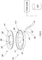
- FIG. 1 is a perspective view of a urine collector according to a preferred embodiment of the present invention.
- FIG. 2 is a sectional view of the urine collector according to the above preferred embodiment of the present invention.
- FIG. 3 illustrates a first alternative mode of the collector of the urine collector according to the above preferred embodiment of the present invention, illustrating the arc-shaped wall of the collector.
- FIG. 4 illustrates a second alternative mode of the collector of the urine collector according to the above preferred embodiment of the present invention, illustrating the inclined wall of the collector.
- FIG. 5 is a perspective view of a urine collector according to a second preferred embodiment of the present invention.
- FIG. 6 is a sectional view of the urine collector according to the second preferred embodiment of the present invention.
- FIG. 7A-7C illustrate different configurations of the urine directing grooves of the urine collector according to the second preferred embodiment of the present invention.
- FIG. 8A is a perspective view of a urine collector according to a third preferred embodiment of the present invention.
- FIG. 8B is a perspective view of the urine collector according to the third preferred embodiment of the present invention.
- FIG. 9A is a perspective view of the urine collector according to the third preferred embodiment of the present invention.
- FIG. 9B is a perspective view of the urine collector according to the third preferred embodiment of the present invention.
- FIG. 10 is a perspective view of a urine collector illustrating an alternative mode of the third preferred embodiment of the present invention.
- FIG. 11 is a perspective view of a urine collector according to a fourth preferred embodiment of the present invention.
- FIG. 12 is a perspective view of the urine collector according to the fourth preferred embodiment of the present invention.
- FIG. 13 is a perspective view of a urine collector according to a fifth preferred embodiment of the present invention.
- FIG. 14 is a perspective view of the urine collector according to the fifth preferred embodiment of the present invention.
- FIG. 15 is a perspective view of a urine collector according to a sixth preferred embodiment of the present invention.
- FIG. 16A is a perspective view of the urine collector according to the sixth preferred embodiment of the present invention.
- FIG. 16B is a perspective view of a urine collector illustrating an alternative mode of the sixth preferred embodiment of the present invention.
- FIG. 16C is a perspective view of a urine collector illustrating an alternative mode of the sixth preferred embodiment of the present invention.
- FIG. 17 is a perspective view of a urine collector according to a seventh preferred embodiment of the present invention.
- FIG. 18 is a perspective view of the urine collector according to the seventh preferred embodiment of the present invention.
- FIG. 19 is a perspective view of a urine collector according to an eighth preferred embodiment of the present invention.
- FIG. 20 is a perspective view of the urine collector according to the eighth preferred embodiment of the present invention.
- a urine collector according to a preferred embodiment of the present invention is illustrated, wherein the urine collector comprises a collector 1 having a top opening and a cavity, a transporting tube 2 , which is made of PET material, connected to the collector 1 for transporting the urine, and a container 3 operatively connected with the transporting tube 2 for containing the urine from the collector 1 through the transporting tube 2 .
- the collector 1 is a pot-shaped collector and made of a rigid plastic material.
- the collector 1 comprises a urine guider 11 provided at a bottom portion of the collector 1 for guiding urine at the urine guider 11 within the cavity, and a discharging unit 12 operatively connected with the urine guider 11 of the collector 1 , wherein the urine guider 11 is a guiding groove indented around a peripheral portion of the bottom wall of the collector 1 .
- a top portion of the urine guider 11 is lower than the bottom wall of the collector 1 .
- the collector 1 further comprises a surrounding wall, wherein the surrounding wall is a vertical wall extended with respect to the bottom wall of the collector 1 that the size of the top opening of the collector 1 matches the size of the bottom side of the collector 1 .
- the urine guider 11 is formed between the surrounding wall and the bottom wall of the collector 1 .
- the collector 1 further comprises a ring-shaped top cover 13 coaxially coupled on a top edge of the collector 1 to partially cover the top opening thereof, wherein the top cover 13 is preferably made of latex.
- a top side of the top cover 13 is inclinedly extended from an outer peripheral edge toward a center, so as to extend toward the top opening of the collector 1 to guide the urine toward the container 1 through the top opening thereof.
- the slope of the top side of the top cover 13 is gradually decreased from an outer edge of the top cover 13 to an inner edge thereof.
- the discharging unit 12 comprises a collecting port 121 located at the surrounding wall of the container 1 and a discharging port 122 , wherein the collecting port 121 is operatively linked with the urine guider 11 and the discharging port 122 is operatively linked with the transporting tube 2 , and the collecting port 121 and the discharging port 122 are operatively connected with each other.
- the discharging port 122 is connected to the inner wall of the transporting tube 2 .
- the urine moves along the guider 11 to reach the collecting port 121 , and passes through the collecting port 121 and the discharging port 122 respectively, so as to reach the transporting tube 2 , and then the urine moves along the transporting tube 2 to be guide into the container 3 .
- the collector 1 is placed below a hip of the patient, especially female patient, wherein the collector serves as a temporary collecting station for guiding the urine to flow into the container 3 .
- FIG. 3 illustrates a first alternative mode the urine collector, wherein the urine collector comprises a collector 1 having a top opening and a cavity, a transporting tube 2 , which is made of latex material, connected to the collector 1 for transporting the urine, and a container 3 operatively connected with the transporting tube 2 for containing the urine from the collector 1 through the transporting tube 2 .
- the collector 1 is a pot-shaped collector and made of a rigid rubber material.
- the collector 1 comprises a urine guider 11 provided at a bottom portion of the collector 1 for guiding urine at the urine guider 11 within the cavity, and a discharging unit 12 operatively connected with the urine guider 11 of the collector 1 , wherein the urine guider 11 is a guiding groove indented around a peripheral portion of the bottom wall of the collector 1 .
- a top portion of the urine guider 11 is lower than the bottom wall of the collector 1 .
- the collector 1 further comprises a surrounding wall, wherein the surrounding wall is an arc-shaped wall extended with respect to the bottom wall of the collector 1 that the size of the top opening of the collector 1 is larger than the size of the bottom wall of the collector 1 .
- the urine guider 11 is formed between the surrounding wall and the bottom wall of the collector 1 .
- the collector 1 further comprises a ring-shaped top cover 13 coaxially coupled on a top edge of the collector 1 to partially cover the top opening thereof, wherein the top cover 13 is preferably made of latex.
- a top side of the top cover 13 is inclinedly extended from an outer peripheral edge toward a center, so as to extend toward the top opening of the collector 1 to guide the urine toward the container 1 through the top opening thereof.
- the slope of the top side of the top cover 13 is gradually decreased from an outer edge of the top cover 13 to an inner edge thereof.
- the discharging unit 12 comprises a collecting port 121 located at the surrounding wall of the container 1 and a discharging port 122 , wherein the collecting port 121 is operatively linked with the urine guider 11 and the discharging port 122 is operatively linked with the transporting tube 2 , and the collecting port 121 and the discharging port 122 are operatively connected with each other.
- the discharging port 122 is connected to the outer wall of the transporting tube 2 . In other words, the urine moves along the guider 11 to reach the collecting port 121 , and passes through the collecting port 121 and the discharging port 122 respectively, so as to reach the transporting tube 2 , and then the urine moves along the transporting tube 2 to be guide into the container 3 .
- the collector 1 is placed below a hip of the patient, especially female patient, wherein the collector serves as a temporary collecting station for guiding the urine to flow into the container 3 .
- FIG. 4 illustrates a second alternative mode the urine collector, wherein the urine collector comprises a collector 1 having a top opening and a cavity, a transporting tube 2 , which is made of polycarbonate material, connected to the collector 1 for transporting the urine, and a container 3 operatively connected with the transporting tube 2 for containing the urine from the collector 1 through the transporting tube 2 .
- the collector 1 is a pot-shaped collector and made of a rigid rubber material.
- the collector 1 comprises a urine guider 11 provided at a bottom portion of the collector 1 for guiding urine at the urine guider 11 within the cavity, and a discharging unit 12 operatively connected with the urine guider 11 of the collector 1 , wherein the urine guider 11 is a guiding groove indented around a peripheral portion of the bottom wall of the collector 1 .
- a top portion of the urine guider 11 is lower than the bottom wall of the collector 1 .
- the collector 1 further comprises a surrounding wall, wherein the surrounding wall is an inclined wall extended with respect to the bottom wall of the collector 1 that the size of the container 1 is gradually reduced from the top opening of the collector 1 to the bottom wall of the collector 1 .
- the urine guider 11 is formed between the surrounding wall and the bottom wall of the collector 1 .
- the collector 1 further comprises a ring-shaped top cover 13 coaxially coupled on a top edge of the collector 1 to partially cover the top opening thereof, wherein the top cover 13 is preferably made of latex.
- a top side of the top cover 13 is inclinedly extended from an outer peripheral edge toward a center, so as to extend toward the top opening of the collector 1 to guide the urine toward the container 1 through the top opening thereof.
- the slope of the top side of the top cover 13 is gradually decreased from an outer edge of the top cover 13 to an inner edge thereof.
- the discharging unit 12 comprises a collecting port 121 located at the surrounding wall of the container 1 and a discharging port 122 , wherein the collecting port 121 is operatively linked with the urine guider 11 and the discharging port 122 is operatively linked with the transporting tube 2 , and the collecting port 121 and the discharging port 122 are operatively connected with each other.
- the discharging port 122 is connected to the outer wall of the transporting tube 2 . In other words, the urine moves along the guider 11 to reach the collecting port 121 , and passes through the collecting port 121 and the discharging port 122 respectively, so as to reach the transporting tube 2 , and then the urine moves along the transporting tube 2 to be guide into the container 3 .
- the collector 1 is placed below a hip of the patient, especially female patient, wherein the collector serves as a temporary collecting station for guiding the urine to flow into the container 3 .
- a urine collector according to a second embodiment illustrates an alternative mode of the first embodiment, wherein the urine collector is arranged for collecting urine from a user, especially a female user.
- the urine collector comprises a basin which comprises a collector 10 ′ and a top cover 20 ′, and a urine guider 30 ′.
- the basin has a cavity for collecting urine, a top side having a size adapted for covering a hip of the user, and a top opening formed at the top side to communicate with the cavity.
- the basin is arranged for being placed underneath the hip of the user, such that the top side of the basin is large enough to cover the urethra of the user to prevent the leakage of the urine.
- the user is able to sit on the top side of the basin to collect the urine in the cavity through the top opening.
- the top opening of the basin is large enough to cover the urethra of the user.
- the collector 10 ′ has a bottom wall 11 ′ and a surrounding wall 12 ′ upwardly extended from the bottom wall 11 ′ to define the cavity within the bottom wall 11 ′ and the surrounding wall 12 ′. Accordingly, the collector 10 ′ is a shallow pan configuration that the collector 10 ′ can be slid underneath the hip of the user. Preferably, the depth of the cavity, i.e. the height of the surrounding wall 12 ′, is about one inch deep.
- the collector 10 ′ is preferably configured to have a circular shape. It is appreciated that the collector 10 ′ can be formed in oval shape or irregular shape.
- the bottom wall 11 ′ of the collector 10 ′ can be a flat bottom wall.
- the top cover 20 ′ is detachably supported on top of the collector 10 ′, wherein the top cover 20 ′ has a ring shape defining an outer peripheral edge 21 ′, an inner peripheral edge 22 ′, and a through hole 23 ′ within the inner peripheral edge 22 ′.
- the top opening of the basin is defined at the through hole 23 ′ of the top cover 20 ′ and the top side of the basin is defined at the top side of the top cover 20 ′.
- the outer peripheral edge 21 ′ of the top cover 20 ′ is detachably coupled at the surrounding wall 12 ′ of the collector 10 ′.
- a coupling slot 111 ′ is formed at a top edge of the surrounding wall 12 ′ of the collector 10 ′, wherein the outer peripheral edge 21 ′ of the top cover 20 ′ is detachably coupled at the coupling slot 111 ′ of the collector 10 ′.
- the surrounding wall 12 ′ of the collector 10 ′ can be configured to have a vertical wall, an arc-shaped wall, or an inclined wall as mentioned in the first embodiment.
- the top side of the top cover 20 ′ is sloped downwardly from the outer peripheral edge 21 ′ of the top cover 20 ′ to the inner peripheral edge 22 ′ thereof for guiding the urine to flow into the collector 10 ′.
- the slanted top side of the top cover 20 ′ will guide the urine to flow toward the through hole 23 ′ so as to collect the urine in the collector 10 ′.
- the top cover 20 ′ further has a plurality of urine directing grooves 24 ′ indently formed on the top side of the top cover 20 ′ and extended to the inner peripheral edge 22 ′ thereof for guiding the urine to flow toward the through hole 23 ′ of the top cover 20 ′.
- the urine directing grooves 24 ′ are grouped into a first groove set and a second groove set, wherein the first and second groove sets are intersected with each other.
- the urine directing grooves 24 ′ are elongated straight grooves radially extended toward the through hole 23 ′ of the top cover 20 ′.
- the urine directing grooves 24 ′ can be configured to have different shapes and sizes, such as circular shape, star shape, or rectangular shape, on the top side of the top cover 20 ′ to guide the flow of urine into the cavity, as shown in FIG. 7 .
- the urine guider 30 ′ is provided at a bottom portion of the basin for collecting urine at the urine guider 30 ′ within the cavity of the basin.
- the urine guider 30 ′ is provided at the bottom wall 11 ′ of the collector 10 ′ at a peripheral portion thereof for collecting the urine at the urine guider 30 ′ within the cavity of the basin so as to enhance a stabilization of the collector 10 ′ after the urine is collected. It is worth mentioning that when the urine is collected in the cavity of the collector 10 ′, the urine will be moved by the movement of the collector 10 ′. Therefore, the center of mass of the basin will be shifted, which may cause the basin to be flipped unintentionally.
- the urine When the urine is collected at the urine guider 30 ′ around the peripheral portion of the bottom wall 11 ′ of the collector 10 ′, the urine will be retained at the peripheral portion of the collector 10 ′ by the weight force, such that the collector 10 ′ can be stabilized to minimize the shifting of the center of mass due to the movement of the collector 10 ′.
- the urine guider 30 ′ is integrated with the bottom wall 11 ′ of the collector 10 ′ that the bottom wall 11 ′ is a convex wall radially sloping down toward the peripheral portion for collecting the urine at the peripheral portion of the collector 10 ′ so as to enhance a stabilization of the collector 10 ′ after the urine is collected.
- the urine guider 30 ′ can be configured to have a guiding groove indentedly formed at the peripheral portion of the bottom wall 11 ′ of the collector 10 ′, as mentioned in the first embodiment, for collecting the urine at the peripheral portion of the collector 10 ′ so as to enhance a stabilization of the collector 10 ′ after the urine is collected.
- the urine collector further comprises a discharging unit 40 ′ operatively connected with the urine guider 30 ′ for discharging the urine therefrom, wherein the discharging unit 40 ′ comprises a discharging port 41 ′ formed at the basin to communicate with the urine guider 30 ′ and a transporting tube 42 ′ detachably coupled at the discharging port 41 ′ for discharging the urine at the urine guider 30 ′ through the discharging port 41 ′.
- the discharging port 41 ′ is through slot formed at the surrounding wall 12 ′ of the collector 10 ′ at the lower portion thereof to communicate with the urine guider 30 ′.
- the discharging unit 40 ′ further comprises a discharging valve 43 ′ coupled at the discharging port 41 ′, such that the discharging valve 43 ′ is selectively opened for discharging urine from the urine guider 30 ′ and closed for retaining urine at the urine guider 30 ′.
- the discharging port 41 ′ is formed at the surrounding wall 12 ′ of the collector 10 ′, such that the bottom wall 11 ′ of the collector 10 ′ can be stably placed on a supporting surface, such as bed surface.
- the discharging unit 40 ′ further comprises a container 44 ′ detachably linked to the transporting tube 42 ′ for collecting urine from the urine guider 30 ′ through the transporting tube 42 ′.
- the transporting tube 42 ′ has one end detachably coupled at the discharging port 41 ′ and an opposed end detachably coupled to the container 44 ′. Therefore, once the discharging valve 43 ′ is opened, the urine at the urine guider 30 ′ will be discharged to the container 44 ′ through the transporting tube 42 ′.
- the transporting tube 42 ′ can be extended to a drain outlet to directly discharge the urine to the drain outlet without the container 44 ′.
- the user is able to place the basin under the hip of the user, wherein the user is able to sit on top of the basin to align the urethra of the user within the top opening of the basin.
- the urine will be temporary stored at the urine guider 30 ′ and will then be guided to discharge to the container 44 ′.
- the user is able to re-use the basin for a relatively long period of time, such as overnight, without directly draining the urine out of the basin manually, so as to reduce the workload of the healthcare worker or family member.
- the urine collector can be cleaned by directly pouring clean water into the cavity of the collector 10 ′ through the top opening to rinse the entire urine collector and discharging the water from the collector 10 ′ to the container 30 ′.
- the collector 1 , 10 ′ can be made of polymer materials, such as rigid plastic, rigid rubber, or polycarbonate materials.
- the collector 1 , 10 ′ is made of light in weight materials, the collector 1 , 10 ′ is easy to be carried, and it is convenient for the patients to use.
- the transporting tube 2 , 42 ′ of the embodiments and their alternatives can be made of PET, silica gel, and latex, such that the above mentioned materials are light in weight and are durable.
- the urine collector of the present invention is constructed in a compact structure that has a relatively thinner structure and a light weight, such that the urine collector can discharge urine continuously and be used by the patients for overnight. In other words, health care workers do not need to frequently unload the urine in the urine collector of the present invention.
- the urine collector of the present invention is adapted to collect urine throughout the hip area but not limiting to the urination portion, so as to prevent leaking out of urine.
- a top side a top cover of the collector of the urine collector is inclinedly extended from an outer peripheral edge toward a center, so as to ensure and guide all the urine be collected toward a container through a top opening of the collector to avoid splashing and leakage. Since the collector is not used to store urine being collected but to function as a transition means to continue to guide the container, the collector can be constructed in compact size with a thinner thickness and a lighter weight that enables an overnight usage without the need to replace the collector.
- the patient can place the collector in position by himself or herself and there is no need to have anyone to help for urination.
- the collector can be directly connected to the sewage drain system that links to a urine collection container for ease of filtration or disinfection treatment, so that the present invention can save a lot of manpower and meet the environmental health requirement.
- the urine collector of the present invention is suitable for all kinds of people to collect urine in bed, especially for post-partum women, seniors, people with problems of frequent urination or urinary incontinence, and injured and sick patients. It is a urine collector enabling people in bed to urinate without leakage and avoiding overflowing of urine.
- the present invention provides a simple structure and compact size that can be manufactured by inexpensive material and in low cost, especially good for mass production without using complicated and expensive production tools and machines, benefiting both the consumers and the manufacturers.
- a urine collector according to a third embodiment illustrates an alternative mode of the first embodiment, wherein the urine collector is arranged for collecting urine for a user, especially for a special patient who is not easy to move around such as a vertebral fracture patient, a bone fracture patient, an apoplexy patients and obese patient.
- the urine collector comprises a basin which comprises a collector 10 A and a top cover 20 A, and a urine guider 30 A.
- the basin has a cavity for collecting urine, a top side having a size adapted for covering a hip of the user, and a top opening formed at the top side to communicate with the cavity.
- the basin is arranged for being placed underneath the hip of the user, such that the top side of the basin is large enough to cover the urethra of the user to prevent the leakage of the urine.
- the user is able to sit on the top side of the basin to collect the urine in the cavity through the top opening.
- the top opening of the basin is large enough to cover the urethra of the user.
- the collector 10 A comprises a bottom wall 11 A and a surrounding wall 12 A upwardly extended from the bottom wall 11 A to define the cavity within the bottom wall 11 A and the surrounding wall 12 A. Accordingly, the collector 10 A is a shallow pan configuration that the collector 10 A can be slid underneath the hip of the user. Preferably, the collector 10 A is preferably configured to have a circular shape. It is appreciated that the collector 10 A can be formed in oval shape or irregular shape.
- the bottom wall 11 A of the collector 10 A can be a flat bottom wall.
- the collector 10 A and the urine guider 30 A are made of metallic material such as stainless steel.
- the urine collector of the second embodiment can be made of plastic and is portable to use, the urine collector of the third embodiment is steady.
- the bottom wall 11 A of the urine collector of the third embodiment further comprises an enlarge bottom base 111 A defining a guiding slot 1110 A, and an inner concave guiding bottom 112 A extended inward and upward from the enlarge bottom base 111 A, in such a manner that the urine on the inner concave guiding bottom 112 A is guided to the enlarge bottom base 111 A.
- the urine cannot largely remained on the inner concave guiding bottom 112 A of the bottom wall 11 A and is timely guided to the enlarge bottom base 111 A, so that the collector 10 A can be stabilized to minimize the shifting of the center of mass due to the movement of the collector 10 A.
- the urine collector further comprises a discharging unit 40 A operatively connected with the urine guider 30 A for discharging the urine therefrom, wherein the discharging unit 40 A comprises a discharging port 41 A formed at the basin to communicate with the urine guider 30 A and a transporting tube 42 A detachably coupled at the discharging port 41 A for discharging the urine at the urine guider 30 A through the discharging port 41 A. More specifically, the discharging port 41 A is through slot formed at the surrounding wall 12 A of the collector 10 A at the lower portion thereof to communicate with the urine guider 30 A.
- the discharging unit 40 A further comprises a discharging valve 43 A coupled at the discharging port 41 A, such that the discharging valve 43 A is selectively opened for discharging urine from the urine guider 30 A and closed for retaining urine at the urine guider 30 A.
- the discharging port 41 A is formed at the lower portion of the surrounding wall 12 A of the collector 10 A; furthermore, the bottom of the discharging port 41 A and the bottom of the enlarge bottom base 111 A are in the same horizontal surface; in such a manner that the enlarge bottom base 111 A of the bottom wall 11 A of the collector 10 A can be stably placed on a supporting surface, and the urine cannot largely remained in the enlarge bottom base 111 A of the bottom wall 11 A and is timely guided to the discharging port 41 A of the discharging unit 40 A.
- the collector 10 A and the urine guider 30 A are large and flat enough to form a large pallet shape and are made of metallic material such that the urine collector is stable enough to stand and to prevent from being overturned.
- the enlarge bottom base 111 A of the bottom wall 11 A has an large contacting area and the urine is timely guided to the discharging port 41 A of the discharging unit 40 A from the enlarge bottom base 111 A of the bottom wall 11 A, so that the urine collector has a good cushioning effect, so that the continuous and overnight urine of patients will not spill over from the urine collector.
- the collector 10 A and the urine guider 30 A are stable enough to handle the overall hip portion of the patients and the top cover 20 A, so that the urine has not leakage and spilling out problems, thereby solving the urinating problem of the special patients who are not easy to move around such as vertebral fracture patients, bone fracture patients, apoplexy patients and obese patients.
- the top cover 20 A is detachably supported on top of the collector 10 A, wherein the top cover 20 A has a ring shape defining an outer peripheral edge 21 A, an inner peripheral edge 22 A, and a through hole 23 A within the inner peripheral edge 22 A.
- the top opening of the basin is defined at the through hole 23 A of the top cover 20 A and the top side of the basin is defined at the top side of the top cover 20 A.
- the top side of the top cover 20 A is sloped downwardly from the outer peripheral edge 21 A of the top cover 20 A to the inner peripheral edge 22 A thereof for guiding the urine to flow into the collector 10 A.
- the slanted top side of the top cover 20 A will guide the urine to flow toward the through hole 23 A so as to collect the urine in the collector 10 A.
- the top cover 20 A is made of metal or plastic and is stabilized to support hips of patients.
- the top cover 20 A further comprises a plurality of urine flow holes 24 A evenly distributed on the top side of the top cover 20 A and are evenly arranged between the outer peripheral edge 21 A and the inner peripheral edge 22 A.
- the urine flow holes 24 A are circular or square.
- the urine flow holes 24 A can also be configured to have different shapes and sizes, such as star shape or rectangular shape. In such a manner that the top cover 20 A will guide the urine to flow toward the through hole 23 A so as to collect the urine in the collector and the hip portion which is contacted with the top cover 20 A can keep dry and comfortable to prevent bedsore.
- the hip portion can easy to separate from the top cover 20 A of the urine collector.
- the surrounding wall 12 A of the collector 10 A can be configured to have a vertical wall, an arc-shaped wall, or an inclined wall as mentioned in the first embodiment.
- the urine collector in the second embodiment has a light and portable pan configuration and can be self-help used by general bedridden patient; while the urine collector in the third embodiment has a stable pan configuration and is especially suitable for the patients who are not easy to move around.
- both of the urine collector in the second embodiment and in the third embodiment have thin configuration.
- the height of the urine collector is only 2.0 cm to 2.5 cm. The patients only has to slightly raise his or her hip for using the urine, therefore, the urine collector is especially suitable for the unmovable patients.
- the urine collector in the third embodiment can be systematic used by the hospitals or the nursing home.
- the urine collector can be installed in the sickbed and the urine can be guided through the transporting tube 42 A to a uniform urine collection pool for unified disposal.
- the urine collector further comprises a urine isolating net 80 A detachably attached on the center of the top cover 20 A and over the through hole 23 A.
- the urine isolating net 80 A is able to isolate the urine and prevent the urine from splashing, thereby keeping cleaning and dry-touch.
- the urine isolating net 80 A is made of plastic and is disposable after use.
- FIG. 10 of the drawings a urine collector according to an alternative mode of the third embodiment of the present invention is illustrated.
- the urine collector of this alternative mode has a similar structure with the third embodiment as shown in FIG. 8 and FIG. 9 .
- the main difference is the connection of the enlarge bottom base 111 A and the inner concave guiding bottom 112 A.
- the outer peripheral edge of the inner concave guiding bottom 112 A is transversely and upwardly extended from the enlarge bottom base 111 A; while as shown in FIG. 10 of the drawings, the outer peripheral edge of the inner concave guiding bottom 112 A is directly and upwardly extended from the enlarge bottom base 111 A.
- the guiding slot 1110 A defined by the enlarge bottom base 111 A has a flat bottom.
- the urine collector is suitable to be used on both the soft and the hard mattress, thereby preventing the urine collector from sinking into the mattress.
- a urine collector according to a fourth embodiment illustrates an alternative mode of the first embodiment, wherein the urine collector is arranged for collecting urine for a user, especially for a special patient who is not easy to move around such as a vertebral fracture patient, a bone fracture patient, an apoplexy patients and obese patient.
- the urine collector comprises a basin which comprises a collector 10 B and a top cover 20 B, and a urine guider 30 B.
- the structures of the collector 10 B and the urine guider 30 B are similar to the structures thereof in the above embodiments.
- the main improvement is the structure of the top cover 20 B.
- the top cover 20 B has a ring shape defining an outer peripheral edge 21 B, an inner peripheral edge 22 B, a through hole 23 B within the inner peripheral edge 22 B, and a plurality of urine flow holes 24 B evenly arranged between the outer peripheral edge 21 B and the inner peripheral edge 22 B.
- the top cover 20 B further comprises an extending support 25 B extended downwardly along the surrounding wall 12 B of the collector 10 from the outer peripheral edge 21 B.
- the top opening of the basin is defined at the through hole 23 B of the top cover 20 B and the top side of the basin is defined at the top side of the top cover 20 B.
- the diameter of the outer peripheral edge 21 B of the top cover 20 B is slight smaller than the diameter of the collector 10 B.
- the extending support 25 B of the top cover 20 B has three extending support legs spaced arranged with each other.
- the number of the extending supports 25 B can be changed.
- the extending support 25 B when the top cover 20 B is detachably supported on top of the collector 10 B, the extending support 25 B is arranged in the inner side of the collector 10 B.
- the extending support 25 B can also be provided contacting with the outer side of the collector 10 B. Therefore, the top cover 20 B is stably coupled with the collector 10 B and is not easy to be slipped out when the patient uses the urine collector. The top cover 20 B is easy to be taken off from the collector 10 B and is convenient to be cleaned.
- the outer peripheral edge 21 ′ of the top cover 20 ′ is detachably coupled at the coupling slot 111 ′ of the collector 10 ′ as shown in FIG. 5 .
- the connection method of the top cover 20 ′ and the collector 10 ′ is defined as embedding type. While the top cover 20 B is detachable coupled with the collector 10 B in a buckle covering type as shown in FIG. 11 to FIG. 12 of the drawings.
- the inclined top portion of the top cover 20 B is thinness such as being made by 1 mm thickness steel disc with holes so as to reduce the rigidness and to improve comfort.
- the extending support 25 B can widening and thickening to enhance the undertake force of the extending support 25 B.
- the inclined top portion of the top cover 20 B is made of latex to improve comfort.
- the extending support 25 B can also made of latex with proper hardness so as to not only support inclined top portion of the top cover 20 B but also to improve comfort.
- a urine collector according to a fifth embodiment illustrates an alternative mode of the first embodiment, wherein the urine collector is arranged for collecting urine for a user, especially for a special patient who is not easy to move around such as a vertebral fracture patient, a bone fracture patient, an apoplexy patients and obese patient.
- the urine collector comprises a basin which comprises a collector 10 C and a top cover 20 C, and a urine guider 30 C.
- the structure of the urine collector is similar to the structures thereof in the above embodiments.
- the main improvement is that the urine collector in the fifth embodiment further comprises a bottom supporting base 50 C installed on the bottom of the collector 10 C.
- the bottom supporting base 50 C comprises a base plate 54 C, a base surrounding wall 51 C extended upward from the base plate 54 C and has a receiving cavity 53 C defined by the base plate 54 C and the base surrounding wall 51 C.
- the base surrounding wall 51 C has a discharge receiving gap 52 C receiving the discharging port 41 C of the discharging unit 40 C, thereby preventing from affecting the discharging of the urine through the discharging port 41 C.
- the diameter of the bottom supporting base 50 C is slightly larger than the diameter of the collector 10 C.
- the base plate 54 C is thin and the height of the base surrounding wall 51 C is shorter than the height of the surrounding wall 12 C of the collector 10 C.
- the bottom supporting base 50 C is made of metal or plastic. The bottom supporting base 50 C provides a well support force to the collector 10 C, so that the urine collector is not easy to be sank into the bed and is more suitable for the bed with soft mattress, thereby the urine being quick and completely discharged from the collector 10 C to the discharging unit 40 C.
- a urine collector according to a sixth embodiment illustrates an alternative mode of the first embodiment, wherein the urine collector is arranged for collecting urine for a user, especially for a special patient who is not easy to move around such as a vertebral fracture patient, a bone fracture patient, an apoplexy patients and obese patient.
- the urine collector comprises a basin which comprises a collector 10 D and a top cover 20 D, and a urine guider 30 D.
- the structure of the urine collector is similar to the structures thereof in the above embodiments.
- the main improvement is that the urine collector in the sixth embodiment further comprises a cushioning support tail 60 D extended from the collector 10 D.
- the cushioning support tail 60 D has an upper end 61 D and a base end 62 D.
- the collector 10 D comprises a bottom wall 11 D and a surrounding wall 12 D upwardly extended from the bottom wall 11 D to define the cavity within the bottom wall 11 D and the surrounding wall 12 D.
- the upper end 61 D of the cushioning support tail 60 D is aslope and outward extended from the surrounding wall 12 D of the collector 10 D to the base end 62 D.
- the base end 62 D is in the same horizontal surface with the bottom portion of the surrounding wall 12 D. It is worth mentioning that the connection portion of the surrounding wall 12 D of the collector 10 D and the cushioning support tail 60 D is polished to have a smooth contacting surface, so that the sharp the corner angle is removed and patients feel comfortable sitting on the urine collector.
- the line QR is in the diameter direction of the collector 10 D;
- the line ST is vertical to the line QR and also is a tangent line of the top periphery of the surrounding wall 12 D of the collector 10 D;
- the line NP is vertical to the line ST and has a length double than the distance of the line NP to the line ST;
- the ling MN and the line ST are the tangent lines of the top periphery of the surrounding wall 12 D of the collector 10 D.
- the line MN, the line OP and the line NP are in the same horizontal surface.
- a layer of soft latex is affixed on the top surface of the cushioning support tail 60 D so as to enhance the comfort of the urine collector.
- the cushioning support tail 60 D also enhances the support force of the urine collector, as the base end 62 D of the cushioning support tail 60 D provides an additional supporting portions, so that the cushioning support tail 60 D stably supports the collector 10 D and prevents the collector 10 D from sloping.
- cushioning support tail 60 D also can be used as a handle of the urine collector, so that the urine collector is easy to be moved.
- the urine collector according to an alternative mode of the sixth embodiment is illustrated.
- the urine collector as shown in FIG. 16C improves the structure of the collector 10 D to protect the leg of the patients.
- the urine collector further comprises an extension rim 90 D outward extended from the top of the surrounding wall 12 D of the collector 10 D so as to form a L-shape with the surrounding wall 12 D, thereby enhancing the pressed area of the thighs and preventing abrasion.
- the extension rim 90 D has a 90 degree angle with the surrounding wall 12 D of the collector 10 D and has a width of about 1.5 cm.
- FIG. 16B of the drawings a urine collector according to an alternative mode of the sixth embodiment is illustrated.
- the urine collector as shown in FIG. 16B improves the structure of the collector 10 D and the connection of the cushioning support tail 60 D and the collector 10 D to reduce the harm to the lumbar.
- the surrounding wall 12 D of the collector 10 D is an arc-shaped wall, and the upper end 61 D of the cushioning support tail 60 D is extended from the bottom of the surrounding wall 12 D and the base end 62 D of the cushioning support tail 60 D is horizontally and outward extended from the upper end 61 D.
- a urine collector according to a seventh embodiment illustrates an alternative mode of the first embodiment, wherein the urine collector is arranged for collecting urine for a user, especially for a special patient who is not easy to move around such as a vertebral fracture patient, a bone fracture patient, an apoplexy patients and obese patient.
- the urine collector comprises a basin which comprises a collector 10 E and a top cover 20 E, and a urine guider 30 E.
- the structures of the collector 10 E and the urine guider 30 E are similar to the structures thereof in the above embodiments.
- the main improvement is the structure of the top cover 20 E.
- the top cover 20 E has a ring shape defining an outer peripheral edge 21 E, an inner peripheral edge 22 E, a through hole 23 E within the inner peripheral edge 22 E, and a plurality of urine flow holes 24 E evenly arranged between the outer peripheral edge 21 E and the inner peripheral edge 22 E.
- the top cover 20 E further comprises two cushioning wings 26 E attached on the outer peripheral edge 21 E.
- the two cushioning wings 26 E are arc-shape and are symmetrically attached on the top cover 20 E and correspondingly contact two hip portions, so that main hip portions of the patients are contacted with the two cushioning wings 26 E.
- One end portion of each of the cushioning wings 26 E is detachably affixed on the outer peripheral edge 21 E and other end is transversely and downward extended from the outer peripheral edge 21 E and along the collector 10 E.
- the cushioning wings 26 E have smooth contacting surface for the hip of the patients.
- the cushioning wings 26 E are made of metal, plastic or wood.
- the diameter of the cushioning wings 26 E of the top cover 20 E is slightly larger than the collector 10 E.
- the cushioning wings 26 E are easy to attach and to be cleaned. As the transverse edges of the cushioning wings 26 E are smoothed, the patients feel comfortable sitting on the cushioning wings 26 E.
- a urine collector according to a eighth embodiment illustrates an alternative mode of the first embodiment, wherein the urine collector is arranged for collecting urine for a user, especially for a special patient who is not easy to move around such as a vertebral fracture patient, a bone fracture patient, an apoplexy patients and obese patient.
- the urine collector comprises a basin which comprises a collector 10 F and a top cover 20 F, and a urine guider 30 F.
- the structures of the collector 10 F, the top cover 20 F and the urine guider 30 F are similar to the structures thereof in the above embodiments.
- the main improvement is that the urine collector in the eighth embodiment further comprises a top cap 70 F covered on the collector 10 F or the top cover 20 F of the urine collector.
- the top cap 70 F comprises a main cap body 71 F and a concave handle 72 F extended concavely from the center of the main cap body 71 F.
- the top cap 70 F is covered on the collector 10 F or the top cover 20 F so as to protect the urine collector.
- the diameter of the main cap body 71 F is larger than the diameter of the collector 10 F.
- the outer portion of the concave handle 72 F has a handle such that the top cap 70 F is easy to be lifted.
- the inner portion of the concave handle 72 F is protruded from the inner surface of the main cap body 71 F and is received within the collector 10 F or the top cover 20 F, so that the top cap 70 F is not easy to be slipped off from the collector 10 F or the top cover 20 F.
- a part of the discharging unit is mounted on one side of the collector, while other part of the discharging unit is mounted on other side of the collector, so that the transporting tube has a shorter and directly way to the collector for the discharging of the urine.
- two handles are respectively mounted on two sides of the collector, so that the urine collector is easy to be moved and hung.
Landscapes
- Health & Medical Sciences (AREA)
- Epidemiology (AREA)
- Nursing (AREA)
- Orthopedic Medicine & Surgery (AREA)
- Engineering & Computer Science (AREA)
- Biomedical Technology (AREA)
- Heart & Thoracic Surgery (AREA)
- Vascular Medicine (AREA)
- Life Sciences & Earth Sciences (AREA)
- Animal Behavior & Ethology (AREA)
- General Health & Medical Sciences (AREA)
- Public Health (AREA)
- Veterinary Medicine (AREA)
- External Artificial Organs (AREA)
- Orthopedics, Nursing, And Contraception (AREA)
Abstract
Description
Claims (8)
Priority Applications (1)
| Application Number | Priority Date | Filing Date | Title |
|---|---|---|---|
| US15/920,406 US10821019B2 (en) | 2015-03-26 | 2018-03-13 | Urine collector |
Applications Claiming Priority (3)
| Application Number | Priority Date | Filing Date | Title |
|---|---|---|---|
| US14/670,399 US20150305956A1 (en) | 2014-04-29 | 2015-03-26 | Urine Collector |
| US14/673,784 US20150305917A1 (en) | 2014-04-29 | 2015-03-30 | Urine Collector |
| US15/920,406 US10821019B2 (en) | 2015-03-26 | 2018-03-13 | Urine collector |
Related Parent Applications (1)
| Application Number | Title | Priority Date | Filing Date |
|---|---|---|---|
| US14/673,784 Continuation-In-Part US20150305917A1 (en) | 2014-04-29 | 2015-03-30 | Urine Collector |
Publications (2)
| Publication Number | Publication Date |
|---|---|
| US20180200101A1 US20180200101A1 (en) | 2018-07-19 |
| US10821019B2 true US10821019B2 (en) | 2020-11-03 |
Family
ID=62838357
Family Applications (1)
| Application Number | Title | Priority Date | Filing Date |
|---|---|---|---|
| US15/920,406 Expired - Fee Related US10821019B2 (en) | 2015-03-26 | 2018-03-13 | Urine collector |
Country Status (1)
| Country | Link |
|---|---|
| US (1) | US10821019B2 (en) |
Families Citing this family (68)
| Publication number | Priority date | Publication date | Assignee | Title |
|---|---|---|---|---|
| US11376152B2 (en) | 2014-03-19 | 2022-07-05 | Purewick Corporation | Apparatus and methods for receiving discharged urine |
| US10226376B2 (en) | 2014-03-19 | 2019-03-12 | Purewick Corporation | Apparatus and methods for receiving discharged urine |
| US10952889B2 (en) | 2016-06-02 | 2021-03-23 | Purewick Corporation | Using wicking material to collect liquid for transport |
| US11090183B2 (en) | 2014-11-25 | 2021-08-17 | Purewick Corporation | Container for collecting liquid for transport |
| US10390989B2 (en) | 2014-03-19 | 2019-08-27 | Purewick Corporation | Apparatus and methods for receiving discharged urine |
| US11806266B2 (en) | 2014-03-19 | 2023-11-07 | Purewick Corporation | Apparatus and methods for receiving discharged urine |
| USD928946S1 (en) | 2016-06-02 | 2021-08-24 | Purewick Corporation | Urine receiving apparatus |
| US10376407B2 (en) * | 2016-08-16 | 2019-08-13 | Purewick Corporation | Using wicking material to collect urine from a male for transport |
| US10376406B2 (en) | 2016-07-27 | 2019-08-13 | Purewick Corporation | Male urine collection device using wicking material |
| US10973678B2 (en) | 2016-07-27 | 2021-04-13 | Purewick Corporation | Apparatus and methods for receiving discharged urine |
| CN110612075B (en) | 2017-01-31 | 2022-09-09 | 普利维克公司 | Apparatus and method for receiving excreted urine |
| US11141307B2 (en) * | 2018-02-05 | 2021-10-12 | Gokula Education Foundation (Medical) | Device, system and apparatus for female urine collection |
| CA3098680A1 (en) | 2018-05-01 | 2019-11-07 | Purewick Corporation | Fluid collection garments |
| KR102492111B1 (en) * | 2018-05-01 | 2023-01-27 | 퓨어윅 코포레이션 | Fluid Collection Devices and Methods of Using The Same |
| KR102493455B1 (en) | 2018-05-01 | 2023-01-31 | 퓨어윅 코포레이션 | Fluid collection devices, related systems, and related methods |
| WO2019212949A1 (en) | 2018-05-01 | 2019-11-07 | Purewick Corporation | Fluid collection devices, systems, and methods |
| CN112367949B (en) | 2018-05-01 | 2023-09-12 | 普利维克公司 | Fluid collection devices, related systems and related methods |
| EP3787569B1 (en) | 2018-05-01 | 2025-07-16 | Purewick Corporation | Fluid collection devices and systems |
| US20220226144A1 (en) * | 2019-05-29 | 2022-07-21 | Purewick Corporation | Fluid collection devices and systems having a fluid impermeable barrier with a selectively minimal hardness, thickness, and/or modulus of elasticity |
| USD929578S1 (en) | 2019-06-06 | 2021-08-31 | Purewick Corporation | Urine collection assembly |
| CN110226946B (en) * | 2019-06-12 | 2022-05-17 | 杭州市第三人民医院 | Urinary surgery operation specimen collector |
| WO2020256865A1 (en) | 2019-06-21 | 2020-12-24 | Purewick Corporation | Fluid collection devices including a base securement area, and related systems and methods |
| CN114375187A (en) | 2019-07-11 | 2022-04-19 | 普奥维克有限公司 | Fluid collection devices, systems, and methods |
| EP3999003B1 (en) | 2019-07-19 | 2024-05-01 | Purewick Corporation | Fluid collection devices including at least one shape memory material |
| CN114867435B (en) | 2019-10-28 | 2025-12-23 | 普利维克公司 | Fluid collection assembly including sample port |
| EP4084746B1 (en) | 2020-01-03 | 2025-04-02 | Purewick Corporation | Urine collection devices having a relatively wide portion and an elongated portion and related methods cross-reference to related applications |
| US12589022B2 (en) | 2020-03-19 | 2026-03-31 | Purewick Corporation | Fluid collection assemblies including one or more movement enhancing features |
| US12521288B2 (en) | 2020-03-26 | 2026-01-13 | Purewick Corporation | Multi-layer urine capture device and related methods |
| EP4344685B1 (en) | 2020-04-10 | 2025-06-11 | Purewick Corporation | Fluid collection assemblies including one or more leak prevention features |
| US12447042B2 (en) | 2020-04-17 | 2025-10-21 | Purewick Corporation | Fluid collection assemblies including a fluid impermeable barrier having a sump and a base |
| WO2021211729A1 (en) | 2020-04-17 | 2021-10-21 | Purewick Corporation | Fluid collection devices, systems, and methods securing a protruding portion in position for use |
| WO2021211599A1 (en) | 2020-04-17 | 2021-10-21 | Purewick Corporation | Female external catheter devices having a urethral cup, and related systems and methods |
| WO2021216422A1 (en) | 2020-04-20 | 2021-10-28 | Purewick Corporation | Fluid collection devices adjustable between a vacuum- based orientation and a gravity-based orientation, and related systems and methods |
| US12048643B2 (en) | 2020-05-27 | 2024-07-30 | Purewick Corporation | Fluid collection assemblies including at least one inflation device and methods and systems of using the same |
| USD967409S1 (en) | 2020-07-15 | 2022-10-18 | Purewick Corporation | Urine collection apparatus cover |
| CN111839602A (en) * | 2020-07-31 | 2020-10-30 | 中国人民解放军陆军军医大学第一附属医院 | An anti-pollution urine sample collector |
| WO2022031943A1 (en) | 2020-08-06 | 2022-02-10 | Purewick Corporation | A fluid collection system including a garment and a fluid collection device |
| US20220047410A1 (en) | 2020-08-11 | 2022-02-17 | Purewick Corporation | Fluid collection assemblies defining waist and leg openings |
| US12521272B2 (en) | 2020-09-09 | 2026-01-13 | Purewick Corporation | Fluid collection devices, systems, and methods |
| US12156792B2 (en) | 2020-09-10 | 2024-12-03 | Purewick Corporation | Fluid collection assemblies including at least one inflation device |
| US11801186B2 (en) | 2020-09-10 | 2023-10-31 | Purewick Corporation | Urine storage container handle and lid accessories |
| US12042423B2 (en) | 2020-10-07 | 2024-07-23 | Purewick Corporation | Fluid collection systems including at least one tensioning element |
| US12440370B2 (en) | 2020-10-21 | 2025-10-14 | Purewick Corporation | Apparatus with compressible casing for receiving discharged urine |
| US12208031B2 (en) | 2020-10-21 | 2025-01-28 | Purewick Corporation | Adapters for fluid collection devices |
| US12257174B2 (en) | 2020-10-21 | 2025-03-25 | Purewick Corporation | Fluid collection assemblies including at least one of a protrusion or at least one expandable material |
| US12569365B2 (en) | 2020-10-21 | 2026-03-10 | Purewick Corporation | Fluid collection assemblies including at least one shape memory material disposed in the conduit |
| US12048644B2 (en) | 2020-11-03 | 2024-07-30 | Purewick Corporation | Apparatus for receiving discharged urine |
| US12070432B2 (en) | 2020-11-11 | 2024-08-27 | Purewick Corporation | Urine collection system including a flow meter and related methods |
| US12245967B2 (en) | 2020-11-18 | 2025-03-11 | Purewick Corporation | Fluid collection assemblies including an adjustable spine |
| US12599495B2 (en) | 2021-01-05 | 2026-04-14 | Purewick Corporation | Male external catheter with attachment interface configured to bias against penis |
| US12268627B2 (en) | 2021-01-06 | 2025-04-08 | Purewick Corporation | Fluid collection assemblies including at least one securement body |
| JP2024503636A (en) | 2021-01-07 | 2024-01-26 | ピュアウィック コーポレイション | Wheelchair-secure urine collection system and related methods |
| JP7500744B2 (en) | 2021-01-19 | 2024-06-17 | ピュアウィック コーポレイション | Variable Fluid Collection Devices, Systems, and Methods |
| US12178735B2 (en) | 2021-02-09 | 2024-12-31 | Purewick Corporation | Noise reduction for a urine suction system |
| CN116615162A (en) | 2021-02-26 | 2023-08-18 | 普奥维克有限公司 | Fluid collection device with reservoir between nozzle and barrier and related systems and methods |
| US12558472B2 (en) | 2021-03-05 | 2026-02-24 | Purewick Corporation | Portable fluid collection systems with storage and related methods |
| US12551385B2 (en) | 2021-03-05 | 2026-02-17 | Purewick Corporation | Fluid collection assembly including a tube having porous wicking material for improved fluid transport |
| US11938054B2 (en) | 2021-03-10 | 2024-03-26 | Purewick Corporation | Bodily waste and fluid collection with sacral pad |
| US12458525B2 (en) | 2021-03-10 | 2025-11-04 | Purewick Corporation | Acoustic silencer for a urine suction system |
| US12029677B2 (en) * | 2021-04-06 | 2024-07-09 | Purewick Corporation | Fluid collection devices having a collection bag, and related systems and methods |
| US12233003B2 (en) | 2021-04-29 | 2025-02-25 | Purewick Corporation | Fluid collection assemblies including at least one length adjusting feature |
| US12251333B2 (en) | 2021-05-21 | 2025-03-18 | Purewick Corporation | Fluid collection assemblies including at least one inflation device and methods and systems of using the same |
| US12324767B2 (en) | 2021-05-24 | 2025-06-10 | Purewick Corporation | Fluid collection assembly including a customizable external support and related methods |
| US12150885B2 (en) | 2021-05-26 | 2024-11-26 | Purewick Corporation | Fluid collection system including a cleaning system and methods |
| US12575960B2 (en) | 2021-06-24 | 2026-03-17 | Purewick Corporation | Urine collection systems having one or more of volume, pressure, or flow indicators, and related methods |
| EP4358906A1 (en) * | 2021-06-25 | 2024-05-01 | Purewick Corporation | Fluid collection assemblies exhibiting a relatively thin shape |
| US12551366B2 (en) | 2021-08-02 | 2026-02-17 | Purewick Corporation | Fluid collection devices having multiple fluid collection regions, and related systems and methods |
| US12594062B2 (en) | 2021-09-08 | 2026-04-07 | Purewick Corporation | Fluid collection assemblies including an extension |
Citations (8)
| Publication number | Priority date | Publication date | Assignee | Title |
|---|---|---|---|---|
| US380473A (en) * | 1888-04-03 | Perfumery-stand | ||
| US633004A (en) * | 1898-08-25 | 1899-09-12 | Daniel Hogan | Bed and douche pan. |
| US682680A (en) * | 1901-01-04 | 1901-09-17 | Henrietta C Fribourg | Liquid-soap holder. |
| US2567830A (en) * | 1947-11-22 | 1951-09-11 | Ida M Timian | Sponge rubber bedpan |
| US2955294A (en) * | 1957-12-13 | 1960-10-11 | Silverstein Lilley | Bedpan ramp |
| US3514793A (en) * | 1967-04-12 | 1970-06-02 | Gail West | Multi-purpose cushioned seat |
| US5848443A (en) * | 1997-12-08 | 1998-12-15 | Waugh; Aston | Portable automobile urinal |
| US6079058A (en) * | 1999-04-16 | 2000-06-27 | Green; Michael E. | Inflatable toilet with disposable bag |
Family Cites Families (1)
| Publication number | Priority date | Publication date | Assignee | Title |
|---|---|---|---|---|
| US380478A (en) * | 1888-04-03 | Kate missotjei dtyffey |
-
2018
- 2018-03-13 US US15/920,406 patent/US10821019B2/en not_active Expired - Fee Related
Patent Citations (8)
| Publication number | Priority date | Publication date | Assignee | Title |
|---|---|---|---|---|
| US380473A (en) * | 1888-04-03 | Perfumery-stand | ||
| US633004A (en) * | 1898-08-25 | 1899-09-12 | Daniel Hogan | Bed and douche pan. |
| US682680A (en) * | 1901-01-04 | 1901-09-17 | Henrietta C Fribourg | Liquid-soap holder. |
| US2567830A (en) * | 1947-11-22 | 1951-09-11 | Ida M Timian | Sponge rubber bedpan |
| US2955294A (en) * | 1957-12-13 | 1960-10-11 | Silverstein Lilley | Bedpan ramp |
| US3514793A (en) * | 1967-04-12 | 1970-06-02 | Gail West | Multi-purpose cushioned seat |
| US5848443A (en) * | 1997-12-08 | 1998-12-15 | Waugh; Aston | Portable automobile urinal |
| US6079058A (en) * | 1999-04-16 | 2000-06-27 | Green; Michael E. | Inflatable toilet with disposable bag |
Also Published As
| Publication number | Publication date |
|---|---|
| US20180200101A1 (en) | 2018-07-19 |
Similar Documents
| Publication | Publication Date | Title |
|---|---|---|
| US10821019B2 (en) | Urine collector | |
| US20150305917A1 (en) | Urine Collector | |
| US9687382B2 (en) | Support device for male genitalia | |
| WO2011138660A1 (en) | Bathing system for assisted and non-sufficient bedridden patients | |
| US20180014991A1 (en) | Bellows Urinal | |
| US8453274B1 (en) | Gel enclosed bedpan | |
| US20110179571A1 (en) | Therapeutic medical toilet bed | |
| CN204274873U (en) | Female urine receiving device | |
| US20250107967A1 (en) | Hydrotherapy soaking apparatus and method for use | |
| CN202366061U (en) | Nursing bed with washing function | |
| US7717891B1 (en) | Portable collection and cleansing device | |
| US11648146B2 (en) | Low profile bedpan | |
| EP3731707A1 (en) | Shower base | |
| CN202497379U (en) | A disposable excrement collection device | |
| US11883354B2 (en) | Hydrotherapy soaking chair and method for use | |
| US11071413B2 (en) | Hydrotherapy soaking chair and method for use | |
| CN201701415U (en) | Bedpan capable of collecting feces and urine simultaneously | |
| HK1225269A (en) | Urine collector | |
| HK1225269A1 (en) | Urine collector | |
| CN207666804U (en) | A kind of Sheng bedpan of comfort and health | |
| CN202714785U (en) | Toilet special for hospital care | |
| CN215652246U (en) | Self-care toilet convenient for bedridden patients | |
| CN218165536U (en) | Nursing bedpan | |
| CA1179103A (en) | Urinal utensil for females | |
| CN221534463U (en) | Portable bed cleaning and nursing device |
Legal Events
| Date | Code | Title | Description |
|---|---|---|---|
| FEPP | Fee payment procedure |
Free format text: ENTITY STATUS SET TO UNDISCOUNTED (ORIGINAL EVENT CODE: BIG.); ENTITY STATUS OF PATENT OWNER: SMALL ENTITY |
|
| FEPP | Fee payment procedure |
Free format text: ENTITY STATUS SET TO SMALL (ORIGINAL EVENT CODE: SMAL); ENTITY STATUS OF PATENT OWNER: SMALL ENTITY |
|
| STPP | Information on status: patent application and granting procedure in general |
Free format text: DOCKETED NEW CASE - READY FOR EXAMINATION |
|
| STPP | Information on status: patent application and granting procedure in general |
Free format text: NON FINAL ACTION MAILED |
|
| STPP | Information on status: patent application and granting procedure in general |
Free format text: RESPONSE TO NON-FINAL OFFICE ACTION ENTERED AND FORWARDED TO EXAMINER |
|
| STPP | Information on status: patent application and granting procedure in general |
Free format text: PUBLICATIONS -- ISSUE FEE PAYMENT VERIFIED |
|
| STCF | Information on status: patent grant |
Free format text: PATENTED CASE |
|
| FEPP | Fee payment procedure |
Free format text: MAINTENANCE FEE REMINDER MAILED (ORIGINAL EVENT CODE: REM.); ENTITY STATUS OF PATENT OWNER: SMALL ENTITY |
|
| LAPS | Lapse for failure to pay maintenance fees |
Free format text: PATENT EXPIRED FOR FAILURE TO PAY MAINTENANCE FEES (ORIGINAL EVENT CODE: EXP.); ENTITY STATUS OF PATENT OWNER: SMALL ENTITY |
|
| STCH | Information on status: patent discontinuation |
Free format text: PATENT EXPIRED DUE TO NONPAYMENT OF MAINTENANCE FEES UNDER 37 CFR 1.362 |
|
| FP | Lapsed due to failure to pay maintenance fee |
Effective date: 20241103 |