US10557879B2 - Sensor excitation in systems where remote sensor signal processing is performed - Google Patents
Sensor excitation in systems where remote sensor signal processing is performed Download PDFInfo
- Publication number
- US10557879B2 US10557879B2 US15/614,293 US201715614293A US10557879B2 US 10557879 B2 US10557879 B2 US 10557879B2 US 201715614293 A US201715614293 A US 201715614293A US 10557879 B2 US10557879 B2 US 10557879B2
- Authority
- US
- United States
- Prior art keywords
- sensor
- signal
- host controller
- power
- interface
- Prior art date
- Legal status (The legal status is an assumption and is not a legal conclusion. Google has not performed a legal analysis and makes no representation as to the accuracy of the status listed.)
- Active, expires
Links
- 230000005284 excitation Effects 0.000 title claims description 11
- 238000004891 communication Methods 0.000 claims description 29
- 238000000034 method Methods 0.000 claims description 27
- 230000008901 benefit Effects 0.000 description 6
- 230000008878 coupling Effects 0.000 description 4
- 238000010168 coupling process Methods 0.000 description 4
- 238000005859 coupling reaction Methods 0.000 description 4
- 230000001939 inductive effect Effects 0.000 description 3
- 230000005294 ferromagnetic effect Effects 0.000 description 2
- 230000015572 biosynthetic process Effects 0.000 description 1
- 230000005672 electromagnetic field Effects 0.000 description 1
- 238000011084 recovery Methods 0.000 description 1
- 238000003786 synthesis reaction Methods 0.000 description 1
Images


Classifications
-
- G—PHYSICS
- G01—MEASURING; TESTING
- G01R—MEASURING ELECTRIC VARIABLES; MEASURING MAGNETIC VARIABLES
- G01R29/00—Arrangements for measuring or indicating electric quantities not covered by groups G01R19/00 - G01R27/00
- G01R29/08—Measuring electromagnetic field characteristics
- G01R29/0864—Measuring electromagnetic field characteristics characterised by constructional or functional features
- G01R29/0878—Sensors; antennas; probes; detectors
-
- G—PHYSICS
- G01—MEASURING; TESTING
- G01F—MEASURING VOLUME, VOLUME FLOW, MASS FLOW OR LIQUID LEVEL; METERING BY VOLUME
- G01F1/00—Measuring the volume flow or mass flow of fluid or fluent solid material wherein the fluid passes through a meter in a continuous flow
- G01F1/56—Measuring the volume flow or mass flow of fluid or fluent solid material wherein the fluid passes through a meter in a continuous flow by using electric or magnetic effects
- G01F1/58—Measuring the volume flow or mass flow of fluid or fluent solid material wherein the fluid passes through a meter in a continuous flow by using electric or magnetic effects by electromagnetic flowmeters
- G01F1/586—Measuring the volume flow or mass flow of fluid or fluent solid material wherein the fluid passes through a meter in a continuous flow by using electric or magnetic effects by electromagnetic flowmeters constructions of coils, magnetic circuits, accessories therefor
-
- G—PHYSICS
- G01—MEASURING; TESTING
- G01F—MEASURING VOLUME, VOLUME FLOW, MASS FLOW OR LIQUID LEVEL; METERING BY VOLUME
- G01F1/00—Measuring the volume flow or mass flow of fluid or fluent solid material wherein the fluid passes through a meter in a continuous flow
- G01F1/56—Measuring the volume flow or mass flow of fluid or fluent solid material wherein the fluid passes through a meter in a continuous flow by using electric or magnetic effects
- G01F1/58—Measuring the volume flow or mass flow of fluid or fluent solid material wherein the fluid passes through a meter in a continuous flow by using electric or magnetic effects by electromagnetic flowmeters
- G01F1/60—Circuits therefor
-
- H—ELECTRICITY
- H01—ELECTRIC ELEMENTS
- H01F—MAGNETS; INDUCTANCES; TRANSFORMERS; SELECTION OF MATERIALS FOR THEIR MAGNETIC PROPERTIES
- H01F27/00—Details of transformers or inductances, in general
- H01F27/28—Coils; Windings; Conductive connections
-
- H—ELECTRICITY
- H01—ELECTRIC ELEMENTS
- H01F—MAGNETS; INDUCTANCES; TRANSFORMERS; SELECTION OF MATERIALS FOR THEIR MAGNETIC PROPERTIES
- H01F27/00—Details of transformers or inductances, in general
- H01F27/42—Circuits specially adapted for the purpose of modifying, or compensating for, electric characteristics of transformers, reactors, or choke coils
-
- H—ELECTRICITY
- H01—ELECTRIC ELEMENTS
- H01F—MAGNETS; INDUCTANCES; TRANSFORMERS; SELECTION OF MATERIALS FOR THEIR MAGNETIC PROPERTIES
- H01F7/00—Magnets
- H01F7/06—Electromagnets; Actuators including electromagnets
- H01F7/064—Circuit arrangements for actuating electromagnets
-
- H—ELECTRICITY
- H02—GENERATION; CONVERSION OR DISTRIBUTION OF ELECTRIC POWER
- H02M—APPARATUS FOR CONVERSION BETWEEN AC AND AC, BETWEEN AC AND DC, OR BETWEEN DC AND DC, AND FOR USE WITH MAINS OR SIMILAR POWER SUPPLY SYSTEMS; CONVERSION OF DC OR AC INPUT POWER INTO SURGE OUTPUT POWER; CONTROL OR REGULATION THEREOF
- H02M7/00—Conversion of AC power input into DC power output; Conversion of DC power input into AC power output
- H02M7/02—Conversion of AC power input into DC power output without possibility of reversal
-
- H—ELECTRICITY
- H04—ELECTRIC COMMUNICATION TECHNIQUE
- H04Q—SELECTING
- H04Q9/00—Arrangements in telecontrol or telemetry systems for selectively calling a substation from a main station, in which substation desired apparatus is selected for applying a control signal thereto or for obtaining measured values therefrom
Definitions
- the disclosure generally relates to electrical sensing systems, and more particularly to the design of a sensor control system for remote sensors.
- Electromagnetic sensors typically use significant interconnect for sensor excitation and sensor information recovery.
- sensor excitation synthesis may be done remotely at the location of the sensor.
- the size and weight of the circuitry for exciting the sensor may be excessive, resulting in excessive circuitry at the remote location of the sensor.
- the sensor control arrangement may comprise a host controller, a remote sensor interface, a power/data bus extending between the host controller and the remote sensor interface, and an electromagnetic sensor.
- the electromagnetic sensor may be configured to receive an AC signal from the host controller via the power/data bus, and send a sensor signal to the remote sensor interface via the power/data bus.
- the remote sensor interface may receive the AC signal.
- the host controller may comprise a first data communication interface, an excitation signal synthesizer in electronic communication with the first data communication interface, and an amplifier.
- the remote sensor interface may comprise an AC to DC power conditioner, a signal processor, and a second data communication interface.
- the AC to DC power conditioner may receive the AC signal and may convert the AC signal into a DC power signal.
- the signal processor and/or the second data communication interface may be powered by the DC power signal. At least three wires may extend between the sensor and the signal processor.
- the electromagnetic sensor may comprise a linear variable differential transformer.
- the electromagnetic sensor may comprise a rotary variable differential transformer.
- the power/data bus may comprise less than five wires.
- the sensor control arrangement may comprise a host controller located at a first location, a remote sensor interface located at a second location, wherein the second location is spaced apart from the first location by a distance, a power/data bus extending between the host controller and the remote sensor interface, and an electromagnetic sensor in electronic communication with the remote sensor interface, wherein the host controller is configured to send an alternating current (AC) signal to the remote sensor interface via the power/data bus, wherein the electromagnetic sensor is configured to receive the AC signal, and wherein the remote sensor interface is configured to receive an analog sensor signal from the electromagnetic sensor, convert the analog sensor signal to a digital sensor signal, and send the digital sensor signal to the host controller via the power/data bus.
- AC alternating current
- the remote sensor interface may be configured to convert the AC signal to a direct current (DC) signal.
- the electromagnetic sensor may be in electronic communication with the remote sensor interface via at least three wires.
- the electromagnetic sensor may comprise a linear variable differential transformer (LVDT).
- the electromagnetic sensor may comprise a rotary variable differential transformer (RVDT).
- the distance may comprise at least two feet.
- the AC signal and the digital sensor signal may be sent via the same wires of the power/data bus.
- a method for exciting an electromagnetic sensor is disclosed herein, in accordance with various embodiments.
- the method may comprise generating, by a host controller, an alternating current (AC) signal, sending, by the host controller, the AC signal to a remote sensor interface, via a power/signal bus, sending, by the host controller, the AC signal to the electromagnetic sensor, via the power/signal bus, receiving, by the host controller, a sensor feedback signal from the remote sensor interface, and adjusting, by the host controller, a parameter of the AC signal, in response to the sensor feedback signal.
- AC alternating current
- the method may further comprise powering, by the host controller, the remote sensor interface via the AC signal.
- the method may further comprise powering, by the host controller, the electromagnetic sensor via the AC signal.
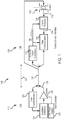
- FIG. 1 illustrates a schematic view of a sensor control arrangement, in accordance with various embodiments
- FIG. 2A illustrates a schematic view of an electromagnetic sensor comprising a linear variable differential transformer (LVDT) having a plurality of wires extending therefrom, in accordance with various embodiments;
- LVDT linear variable differential transformer
- FIG. 2B illustrates a schematic view of an electromagnetic sensor comprising a rotary variable differential transformer (RVDT) having a plurality of wires extending therefrom, in accordance with various embodiments; and
- RVDT rotary variable differential transformer
- FIG. 3 illustrates a method for exciting an electromagnetic sensor, in accordance with various embodiments.
- references to “one embodiment”, “an embodiment”, “various embodiments”, etc. indicate that the embodiment described may include a particular feature, structure, or characteristic, but every embodiment may not necessarily include the particular feature, structure, or characteristic. Moreover, such phrases are not necessarily referring to the same embodiment. Further, when a particular feature, structure, or characteristic is described in connection with an embodiment, it is submitted that it is within the knowledge of one skilled in the art to affect such feature, structure, or characteristic in connection with other embodiments whether or not explicitly described. After reading the description, it will be apparent to one skilled in the relevant art(s) how to implement the disclosure in alternative embodiments.
- electro communication means communication of electronic signals with physical coupling (e.g., “electrical communication” or “electrically coupled”) or without physical coupling and via an electromagnetic field (e.g., “inductive communication” or “inductively coupled” or “inductive coupling”).
- electromagnetic field e.g., “inductive communication” or “inductively coupled” or “inductive coupling”.
- use of the term “electronic communication” includes both “electrical communication” and “inductive communication.”
- Sensor control arrangement 100 may comprise a host controller 110 , a power/data bus 120 , and a remote sensor interface 130 .
- Host controller 110 may comprise a data communication interface (also referred to herein as a first data communication interface) 122 , an excitation signal synthesizer 124 , and an amplifier 126 .
- Remote sensor interface 130 may comprise an AC/DC power conditioner 132 , a signal processor 134 , and a data communication interface (also referred to herein as a second data communication interface) 136 .
- Sensor control arrangement 100 may further comprise an electromagnetic sensor 140 .
- remote sensor interface 130 may be located remotely from host controller 110 .
- power/data bus 120 may comprise a length 102 .
- length 102 may be at least two feet (0.6096 m), and in various embodiments, length 102 may be up to 328 feet (100 m) or longer, for example. In this regard, it may be desirable to reduce the number of interconnects between remote sensor interface 130 and host controller 110 to reduce the weight and/or size of sensor control arrangement 100 .
- power/data bus 120 may comprise a plurality of wires. In various embodiments, power/data bus 120 may comprise less than five wires.
- host controller 110 may be located at a first location 104 and remote sensor interface 130 may be located at a second location 106 .
- First location 104 and second location 106 may be separated by a distance being less than or equal to length 102 .
- excitation signal synthesizer 124 may generate an alternating current (AC) signal 125 via amplifier 126 .
- Host controller 110 may send AC signal 125 to remote sensor interface 130 .
- electromagnetic sensor 140 may be similar to linear variable differential transformer (LVDT) 240 or rotary variable differential transformer (RVDT) 260 .
- LVDT 240 may comprise a primary coil 242 , a first secondary coil 244 , a second secondary coil 246 , and a ferromagnetic core 245 .
- LVDT 240 may comprise two primary coil leads (i.e., first primary lead 251 and second primary lead 252 ).
- Primary coil 242 may be excited in response to an excitation signal (e.g., AC signal 250 ) received via first primary lead 251 and second primary lead 252 .
- an excitation signal e.g., AC signal 250
- LVDT 240 may comprise three secondary coil leads (i.e., first secondary lead 253 , second secondary lead 254 , and third secondary lead 255 ).
- first primary lead 251 , second primary lead 252 , first secondary lead 253 , second secondary lead 254 , and third secondary lead 255 may comprise wires.
- RVDT 260 may comprise a primary coil 262 , a first secondary coil 264 , a second secondary coil 266 , and a ferromagnetic core 265 .
- RVDT 260 may comprise two primary coil leads (i.e., first primary lead 271 and second primary lead 272 ).
- Primary coil 262 may be excited in response to an excitation signal (e.g., AC signal 250 ) received via first primary lead 271 and second primary lead 272 .
- RVDT 260 may comprise four secondary coil leads (i.e., first secondary lead 273 , second secondary lead 274 , third secondary lead 275 , and fourth secondary lead 276 ).
- first primary lead 271 , second primary lead 272 , first secondary lead 273 , second secondary lead 274 , third secondary lead 275 , and fourth secondary lead 276 may comprise wires.
- electromagnetic sensor 140 may comprise a plurality of secondary leads. Said secondary leads may be coupled between electromagnetic sensor 140 and signal processor 134 .
- Signal processor 134 may be located in close proximity to electromagnetic sensor 140 .
- the distance between signal processor 134 and sensor 140 may be less than half of the length 102 , and in various embodiments, less than a tenth of the length 102 . In various embodiments, the distance between signal processor 134 and sensor 140 may be less than 3.28 feet (1 m).
- electromagnetic sensor 140 may comprise at least three wires extending between electromagnetic sensor 140 and signal processor 134 . In this regard, the number of wires of power/data bus 120 may be reduced.
- AC signal 125 may be received by electromagnetic sensor 140 .
- Electromagnetic sensor 140 may sense the position of an adjacent component. Electromagnetic sensor 140 may output a sensor signal 142 .
- Sensor signal 142 may comprise an analog signal. In this regard, sensor signal 142 may be referred to herein as an analog sensor signal.
- Sensor signal 142 may be received by signal processor 134 .
- Signal processor 134 may process sensor signal 142 and generate a sensor signal (also referred to herein as a sensor feedback signal) 144 .
- Sensor signal 144 may comprise a digital signal. In this regard, sensor signal 144 may be referred to herein as a digital sensor signal.
- Sensor signal 144 may comprise information regarding parameters of sensor signal 142 (e.g., magnitude, frequency, etc.) as well as position information. Sensor signal 144 may be sent to data communication interface 136 whereby it may be sent to data communication interface 122 via power/data bus 120 . Excitation signal synthesizer 124 may receive sensor signal 144 via data communication interface 122 and may adjust one or more parameters (e.g., magnitude) of AC signal 125 based upon sensor signal 144 . For example, excitation signal synthesizer 124 may determine that the amplitude of sensor signal 142 is below a threshold value and may increase the amplitude of AC signal 125 to increase the power received by electromagnetic sensor 140 , which may in turn increase the amplitude of sensor signal 142 .
- parameters of sensor signal 142 e.g., magnitude, frequency, etc.
- Excitation signal synthesizer 124 may receive sensor signal 144 via data communication interface 122 and may adjust one or more parameters (e.g., magnitude) of AC signal 125 based upon sensor signal
- AC/DC power conditioner 132 may receive AC signal 125 via power/data bus 120 .
- AC/DC power conditioner 132 may convert AC signal 125 into a DC power signal 138 .
- Data communication interface 136 and/or signal processor 134 may be powered via DC power signal 138 .
- DC power signal 138 may comprise, for example, between one and five volts.
- both data and power may be transmitted between host controller 110 and remote sensor interface 130 .
- power/data bus 120 may direct AC signal 125 and sensor signal 144 .
- the power and data signals i.e., AC signal 125 and sensor signal 144
- the power and data signals may be transmitted through physically the same wires of power/data bus 120 .
- the power bus and the data bus may be the same bus.
- Method 300 includes generating an AC signal (step 310 ).
- Method 300 includes sending the AC signal to a remote sensor interface (step 320 ).
- Method 300 includes sending the AC signal to the electromagnetic sensor (step 330 ).
- Method 300 includes powering the remote sensor interface via the AC signal (step 340 ).
- Method 300 includes powering the electromagnetic sensor via the AC signal (step 350 ).
- Method 300 includes receiving a sensor feedback signal from the remote sensor interface (step 360 ).
- Method 300 includes adjusting a parameter of the AC signal in response to the sensor feedback signal (step 370 ).
- step 310 may include generating, by host controller 110 , AC signal 125 .
- Step 320 may include sending, by host controller 110 , AC signal 125 to remote sensor interface 130 , via power/signal bus 120 .
- Step 330 may include sending, by host controller 110 , AC signal 125 to electromagnetic sensor 140 , via power/signal bus 120 .
- Step 340 may include powering, by host controller 110 , remote sensor interface 130 via AC signal 125 .
- Step 350 may include powering, by host controller 110 , electromagnetic sensor 140 via AC signal 125 .
- Step 360 may include receiving, by host controller 110 , a sensor feedback signal (i.e., sensor signal 144 ) from remote sensor interface 130 .
- Step 370 may include adjusting, by host controller 110 , a parameter (e.g., amplitude) of AC signal 125 , in response to the sensor feedback signal (i.e., sensor signal 144 ).
Landscapes
- Engineering & Computer Science (AREA)
- Physics & Mathematics (AREA)
- Power Engineering (AREA)
- Electromagnetism (AREA)
- General Physics & Mathematics (AREA)
- Fluid Mechanics (AREA)
- Computer Networks & Wireless Communication (AREA)
- Arrangements For Transmission Of Measured Signals (AREA)
Abstract
Description
Claims (20)
Priority Applications (2)
| Application Number | Priority Date | Filing Date | Title |
|---|---|---|---|
| US15/614,293 US10557879B2 (en) | 2017-06-05 | 2017-06-05 | Sensor excitation in systems where remote sensor signal processing is performed |
| EP18175506.7A EP3413579B1 (en) | 2017-06-05 | 2018-06-01 | Sensor excitation in systems where remote sensor signal processing is performed |
Applications Claiming Priority (1)
| Application Number | Priority Date | Filing Date | Title |
|---|---|---|---|
| US15/614,293 US10557879B2 (en) | 2017-06-05 | 2017-06-05 | Sensor excitation in systems where remote sensor signal processing is performed |
Publications (2)
| Publication Number | Publication Date |
|---|---|
| US20180348275A1 US20180348275A1 (en) | 2018-12-06 |
| US10557879B2 true US10557879B2 (en) | 2020-02-11 |
Family
ID=62684577
Family Applications (1)
| Application Number | Title | Priority Date | Filing Date |
|---|---|---|---|
| US15/614,293 Active 2038-03-18 US10557879B2 (en) | 2017-06-05 | 2017-06-05 | Sensor excitation in systems where remote sensor signal processing is performed |
Country Status (2)
| Country | Link |
|---|---|
| US (1) | US10557879B2 (en) |
| EP (1) | EP3413579B1 (en) |
Citations (8)
| Publication number | Priority date | Publication date | Assignee | Title |
|---|---|---|---|---|
| US5703576A (en) | 1993-06-14 | 1997-12-30 | Simmonds Precision Products Inc. | Embeddable DC power supply for smart structure sensors |
| US5764927A (en) * | 1995-09-29 | 1998-06-09 | Allen Bradley Company, Inc. | Backplane data transfer technique for industrial automation controllers |
| US20050021712A1 (en) * | 2003-01-24 | 2005-01-27 | Constantin Chassapis | Multi-user, multi-device remote access system |
| CN202372137U (en) | 2011-12-12 | 2012-08-08 | 西安瑞日电子发展有限公司 | Angle sensor demodulation structure on basis of coherent demodulation technology |
| WO2012149008A2 (en) | 2011-04-25 | 2012-11-01 | Endotronix, Inc. | Wireless sensor reader |
| US20150323580A1 (en) * | 2011-12-28 | 2015-11-12 | United Safety, Inc. | Power line proximity sensing and warning system |
| US9389260B2 (en) | 2012-09-28 | 2016-07-12 | General Electric Company | Systems and methods for monitoring sensors |
| CN205508098U (en) | 2015-12-04 | 2016-08-24 | 中国航空工业第六一八研究所 | Low -power consumption wireless sensing demodulator for linear displacement sensor |
-
2017
- 2017-06-05 US US15/614,293 patent/US10557879B2/en active Active
-
2018
- 2018-06-01 EP EP18175506.7A patent/EP3413579B1/en active Active
Patent Citations (8)
| Publication number | Priority date | Publication date | Assignee | Title |
|---|---|---|---|---|
| US5703576A (en) | 1993-06-14 | 1997-12-30 | Simmonds Precision Products Inc. | Embeddable DC power supply for smart structure sensors |
| US5764927A (en) * | 1995-09-29 | 1998-06-09 | Allen Bradley Company, Inc. | Backplane data transfer technique for industrial automation controllers |
| US20050021712A1 (en) * | 2003-01-24 | 2005-01-27 | Constantin Chassapis | Multi-user, multi-device remote access system |
| WO2012149008A2 (en) | 2011-04-25 | 2012-11-01 | Endotronix, Inc. | Wireless sensor reader |
| CN202372137U (en) | 2011-12-12 | 2012-08-08 | 西安瑞日电子发展有限公司 | Angle sensor demodulation structure on basis of coherent demodulation technology |
| US20150323580A1 (en) * | 2011-12-28 | 2015-11-12 | United Safety, Inc. | Power line proximity sensing and warning system |
| US9389260B2 (en) | 2012-09-28 | 2016-07-12 | General Electric Company | Systems and methods for monitoring sensors |
| CN205508098U (en) | 2015-12-04 | 2016-08-24 | 中国航空工业第六一八研究所 | Low -power consumption wireless sensing demodulator for linear displacement sensor |
Non-Patent Citations (1)
| Title |
|---|
| European Patent Office, European Search Report dated Oct. 5, 2018 in Application No. 18175506.7-1215. |
Also Published As
| Publication number | Publication date |
|---|---|
| US20180348275A1 (en) | 2018-12-06 |
| EP3413579A1 (en) | 2018-12-12 |
| EP3413579B1 (en) | 2021-09-15 |
Similar Documents
| Publication | Publication Date | Title |
|---|---|---|
| CN108462260B (en) | Detector, power transmitter and receiver, and power supply system | |
| WO2021141925A1 (en) | Systems and methods for wireless power transfer including pulse width encoded data communications | |
| CN102273040A (en) | Communication across inductive links with dynamic loads | |
| US11848575B2 (en) | Systems and methods for receiver beaconing in wireless power systems | |
| US12301019B2 (en) | Automatic gain control for communications demodulation in wireless power transmitters | |
| US11682926B2 (en) | Automatic gain control for communications demodulation in wireless power transmitters | |
| CN110495072B (en) | Wireless charging device and method for detecting receiver device | |
| CN103575957A (en) | High efficiency energy harvester and methods thereof | |
| JP2019162023A (en) | Wireless power transmission device and power receiving side current detection circuit thereof | |
| US11848574B2 (en) | Automatic gain control for communications demodulation in wireless power transfer systems | |
| US11722011B2 (en) | Systems and methods for receiver beaconing in wireless power systems | |
| CN111505527A (en) | System and Method for Ground Fault Detection Using Hall Effect Sensors | |
| US12592590B2 (en) | Automatic gain control for communications demodulation in wireless power transmitters | |
| US10557879B2 (en) | Sensor excitation in systems where remote sensor signal processing is performed | |
| US11569694B2 (en) | Automatic gain control for communications demodulation in wireless power receivers | |
| US20240235272A1 (en) | Cross talk and interference mitigation in dual wireless power transmitter | |
| CN103714956B (en) | There is the Rotary transformer system of redundant information acquisition function | |
| CN109142944A (en) | Connecting element, sensor and the sensor device for process automation | |
| US8478560B2 (en) | Three wire transformer position sensor, signal processing circuitry, and temperature compensation circuitry therefor | |
| CN109541702B (en) | A large depth MRS transmitting and receiving system and detection method | |
| EP3404841B1 (en) | Two wire power and serial communication | |
| JP6842885B2 (en) | Wireless power supply device and wireless power supply method | |
| US20230134561A1 (en) | Multi-Coil Polygonal Wireless Power Receiver Antenna | |
| CN110277836B (en) | Wireless power transmitter and wireless power transfer system | |
| CN110957905A (en) | Interference suppression filter and method for reducing AC power |
Legal Events
| Date | Code | Title | Description |
|---|---|---|---|
| AS | Assignment |
Owner name: HAMILTON SUNDSTRAND CORPORATION, NORTH CAROLINA Free format text: ASSIGNMENT OF ASSIGNORS INTEREST;ASSIGNOR:LUDICKY, FRANK J;REEL/FRAME:042602/0768 Effective date: 20170605 |
|
| STPP | Information on status: patent application and granting procedure in general |
Free format text: DOCKETED NEW CASE - READY FOR EXAMINATION |
|
| STPP | Information on status: patent application and granting procedure in general |
Free format text: NON FINAL ACTION MAILED |
|
| STPP | Information on status: patent application and granting procedure in general |
Free format text: RESPONSE TO NON-FINAL OFFICE ACTION ENTERED AND FORWARDED TO EXAMINER |
|
| STPP | Information on status: patent application and granting procedure in general |
Free format text: NOTICE OF ALLOWANCE MAILED -- APPLICATION RECEIVED IN OFFICE OF PUBLICATIONS |
|
| STPP | Information on status: patent application and granting procedure in general |
Free format text: PUBLICATIONS -- ISSUE FEE PAYMENT VERIFIED |
|
| STCF | Information on status: patent grant |
Free format text: PATENTED CASE |
|
| MAFP | Maintenance fee payment |
Free format text: PAYMENT OF MAINTENANCE FEE, 4TH YEAR, LARGE ENTITY (ORIGINAL EVENT CODE: M1551); ENTITY STATUS OF PATENT OWNER: LARGE ENTITY Year of fee payment: 4 |