TWM635667U - Assembly-type fiber optic adapter set - Google Patents
Assembly-type fiber optic adapter set Download PDFInfo
- Publication number
- TWM635667U TWM635667U TW111207230U TW111207230U TWM635667U TW M635667 U TWM635667 U TW M635667U TW 111207230 U TW111207230 U TW 111207230U TW 111207230 U TW111207230 U TW 111207230U TW M635667 U TWM635667 U TW M635667U
- Authority
- TW
- Taiwan
- Prior art keywords
- side wall
- base
- sliding parts
- optical fiber
- buckle part
- Prior art date
Links
Images


Landscapes
- Mechanical Coupling Of Light Guides (AREA)
Abstract
一種拼接式光纖適配器組,包括多個相拼接的光纖適配器;其中的第一光纖適配器包括第一座體,第一座體之第一側壁面具有多個第一滑移部及第一卡扣部;第二光纖適配器包括第二座體,第二座體之第一側壁面具有多個第二滑移部及第二卡扣部,各第一滑移部與各第二滑移部分別相結合,第一卡扣部與第二卡扣部相結合;通過多個光纖適配器彼此並排且拼接在一塊,提供多個光纖適配器供多個光纖連接器插接,滿足光纖線靈活佈線的需求。A spliced optical fiber adapter set, including a plurality of spliced optical fiber adapters; wherein the first optical fiber adapter includes a first base, and the first side wall of the first base has a plurality of first sliding parts and first buckles part; the second optical fiber adapter includes a second seat body, the first side wall of the second seat body has a plurality of second sliding parts and second buckle parts, and each first sliding part and each second sliding part are respectively Combined, the first buckle part is combined with the second buckle part; multiple fiber optic adapters are arranged side by side and spliced together to provide multiple fiber optic adapters for multiple fiber optic connectors to be plugged in to meet the needs of flexible routing of fiber optic cables .
Description
本創作係有關於一種適配器,特別是關於一種拼接式光纖適配器組。The invention relates to an adapter, in particular to a spliced optical fiber adapter set.
光纖為光傳導工具,一般光纖連接裝置係由一母座適配器(Adapter)二端插接有公頭光纖適配器作為對接,藉以達到卡固與資料傳輸之目的。Optical fiber is a light transmission tool, and the general optical fiber connection device is a female adapter (Adapter) with a male optical fiber adapter inserted at both ends as a docking, so as to achieve the purpose of clamping and data transmission.
一般Lucent Connector(簡稱LC)Type的光轉接適配器為光傳輸連接器,可以使LC Type光傳輸線進行連接,以傳遞光訊號。LC適配器的孔數固定,分為單孔,雙孔,四孔等,不能滿足靈活的佈線需求,造成佈線空間浪費。Generally, Lucent Connector (abbreviated as LC) Type optical transfer adapter is an optical transmission connector, which can connect LC Type optical transmission lines to transmit optical signals. The number of holes of the LC adapter is fixed, divided into single hole, double hole, four holes, etc., which cannot meet the flexible wiring requirements, resulting in a waste of wiring space.
依據一些實施例,提供一種拼接式光纖適配器組,包括第一光纖適配器與第二光纖適配器;第一光纖適配器包括第一座體,第一座體由四側壁面界定有第一容置槽,第一座體之兩端具有連通於第一容置槽之第一插口,第一座體之第一側壁面具有多個第一滑移部及第一卡扣部;第二光纖適配器包括第二座體,第二座體由四側壁面界定有第二容置槽,第二座體之兩端具有連通於第二容置槽之第二插口,第二座體之第一側壁面具有多個第二滑移部及第二卡扣部,各第一滑移部與各第二滑移部分別相結合,第一卡扣部與第二卡扣部相結合。According to some embodiments, there is provided a spliced fiber optic adapter set, including a first fiber optic adapter and a second fiber optic adapter; the first fiber optic adapter includes a first seat body, and the first seat body is defined by four side walls to define a first accommodating groove, The two ends of the first seat have a first socket connected to the first accommodation groove, the first side wall of the first seat has a plurality of first sliding parts and first buckle parts; the second optical fiber adapter includes a first Two seats, the second seat is defined by four side walls with a second accommodation groove, the two ends of the second seat have a second socket connected to the second accommodation groove, the first side wall of the second seat has a A plurality of second sliding parts and second locking parts, each first sliding part is combined with each second sliding part, and the first locking part is combined with the second locking part.
在一實施例中,各第一滑移部沿一軸向設置於第一座體之第一側壁面,軸向垂直於第一容置槽之插接方向,各第二滑移部沿軸向設置於第二座體之第一側壁面,軸向垂直於第二容置槽之插接方向。In one embodiment, each first sliding part is arranged on the first side wall surface of the first seat body along an axial direction, the axial direction is perpendicular to the insertion direction of the first receiving groove, and each second sliding part is arranged along the axial direction. The direction is arranged on the first side wall surface of the second base body, and the axial direction is perpendicular to the insertion direction of the second accommodating groove.
在一實施例中,各第一滑移部分別位於第一座體之第一側壁面之二邊區域,第一卡扣部位於多個第一滑移部之間,各第二滑移部分別位於第二座體之第一側壁面之二邊區域,第二卡扣部位於多個第二滑移部之間。In one embodiment, each of the first sliding parts is respectively located on the two sides of the first side wall of the first base, the first locking part is located between the plurality of first sliding parts, and each of the second sliding parts They are respectively located on the two side regions of the first side wall of the second base body, and the second locking part is located between the plurality of second sliding parts.
在一實施例中,第一卡扣部相鄰於多個第一滑移部之其中之一,第二卡扣部相鄰於該些第二滑移部之其中之一。In one embodiment, the first locking part is adjacent to one of the first sliding parts, and the second locking part is adjacent to one of the second sliding parts.
在一實施例中,各第一滑移部由第一座體之第二側壁面側端延伸設置至第一座體之第四側壁面側端,各第二滑移部由第二座體之第二側壁面側端延伸設置至第二座體之第四側壁面側端。In one embodiment, each first sliding part extends from the side end of the second side wall of the first seat to the side end of the fourth side wall of the first seat, and each second sliding part extends from the side end of the second side wall of the first seat. The side end of the second side wall is extended to the side end of the fourth side wall of the second base body.
在一實施例中,第一卡扣部具有凹槽及插入口,插入口兩側具有扣合部,第二卡扣部具有凸塊,凸塊由插入口扣入於凹槽內,各扣合部接觸於凸塊限位。In one embodiment, the first buckle part has a groove and an insertion opening, and there are buckling parts on both sides of the insertion opening, and the second buckle part has a protrusion, and the protrusion is buckled into the groove by the insertion opening, and each buckle The joint is in contact with the bump limit.
在一實施例中,第一卡扣部位於第一座體之第一側壁面與第一座體之第二側壁面之間,第二卡扣部位於第二座體之第一側壁面與第二座體之第二側壁面之間。In one embodiment, the first locking part is located between the first side wall of the first seat and the second side wall of the first seat, and the second locking part is located between the first side wall of the second seat and the second side wall of the first seat. Between the second side walls of the second base.
在一實施例中,第一座體之第二側壁面與第二座體之第二側壁面切齊,第一座體之第四側壁面與第二座體之第四側壁面切齊。In one embodiment, the second side wall of the first base is aligned with the second side wall of the second base, and the fourth side wall of the first base is aligned with the fourth side wall of the second base.
在一實施例中,第一卡扣部位於第一座體之第一側壁面與第一座體之第四側壁面之間,第二卡扣部位於第二座體之第一側壁面與第二座體之第四側壁面之間。In one embodiment, the first locking part is located between the first side wall of the first seat and the fourth side wall of the first seat, and the second locking part is located between the first side wall of the second seat and the fourth side wall of the first seat. Between the fourth side walls of the second base.
在一實施例中,第二座體之第三側壁面與第二座體之第一側壁面相對稱位於第二座體之兩側,第二座體之第三側壁面具有多個第三滑移部及第三卡扣部,拼接式光纖適配器組更包括第三光纖適配器,第三光纖適配器包括第三座體,第三座體由四側壁面界定有第三容置槽,第三座體之兩端具有連通於第三容置槽之第三插口,第三座體之第一側壁面具有多個第四滑移部及第四卡扣部,各第三滑移部與各第四滑移部分別相結合,第三卡扣部與第四卡扣部相結合。In one embodiment, the third side wall of the second base is symmetrically located on both sides of the second base with the first side wall of the second base, and the third side wall of the second base has a plurality of third slides. The splicing fiber optic adapter set further includes a third fiber optic adapter. The third fiber optic adapter includes a third seat body. The third seat body is defined by four side walls to define a third accommodating groove. The third seat The two ends of the body have a third socket connected to the third accommodating groove, the first side wall of the third seat body has a plurality of fourth sliding parts and fourth buckle parts, each third sliding part and each third The four sliding parts are respectively combined, and the third buckle part is combined with the fourth buckle part.
綜合上述,依據一些實施例,通過多個光纖適配器彼此並排且拼接在一塊,提供多個光纖適配器供多個光纖連接器插接,滿足光纖線靈活佈線的需求;依據一些實施例,通過多個第一滑移部與多個第二滑移部相結合與第一卡扣部與第二卡扣部相結合的固定作用,使各光纖適配器相對接的側邊不會因為各光纖線向下拉動的力量而使各光纖適配器彼此相脫離。To sum up the above, according to some embodiments, multiple fiber optic adapters are arranged side by side and spliced together to provide multiple fiber optic adapters for multiple fiber optic connectors to meet the needs of flexible wiring of optical fiber cables; The fixing effect of the combination of the first sliding part and multiple second sliding parts and the combination of the first buckle part and the second buckle part prevents the sides of the optical fiber adapters from facing downward due to the fiber optic cables. The pulling force separates the fiber optic adapters from each other.
為使本創作之目的、技術特徵及優點,能更為相關技術領域人員所了解並得以實施本創作,在此配合所附圖式,於後續之說明書闡明本創作之技術特徵與實施方式,並列舉較佳實施例進一步說明,然以下實施例說明並非用以限定本創作,且以下文中所對照之圖式,係表達與本創作特徵有關之示意。In order to make the purpose, technical features and advantages of this creation more understandable to those in the relevant technical field and enable this creation to be implemented, the technical features and implementation methods of this creation are explained in the subsequent instructions in conjunction with the attached drawings, and The preferred embodiments are listed for further description, but the descriptions of the following embodiments are not intended to limit the creation, and the drawings compared with the following are the representations related to the characteristics of the creation.
請同時參閱圖1,圖1為光纖適配器組之外觀示意圖;在一些實施例中,光纖適配器組用以供多個光纖連接器(未圖示)插接,光纖連接器(Lucent Connector,簡稱LC)為適於機櫃等用途的高密度連接應用;光纖適配器組包括並排且拼接的多個光纖適配器,以下以第一光纖適配器1及第二光纖適配器2為例說明。Please refer to Figure 1 at the same time. Figure 1 is a schematic diagram of the appearance of a fiber optic adapter set; ) is suitable for high-density connection applications such as cabinets; the fiber optic adapter set includes a plurality of fiber optic adapters arranged side by side and spliced together. The first fiber
請同時參閱圖2與圖3,圖2為光纖適配器組之分解示意圖,圖3為光纖適配器組組裝時之側視示意圖,第一卡扣部16位於第一座體11之第一側壁面11a的上方,第二卡扣部26位於第二座體21之第一側壁面21a的上方。Please refer to FIG. 2 and FIG. 3 at the same time. FIG. 2 is an exploded view of the fiber optic adapter set. FIG. 3 is a side view of the fiber optic adapter set when assembled. The
第一光纖適配器1包括第一座體11,第一座體11由四側壁面(第一側壁面11a、第二側壁面11b、第三側壁面11c、第四側壁面11d)界定有第一容置槽12,第一座體11之兩端具有連通於第一容置槽12之第一插口13,第一座體11之第一側壁面11a具有多個第一滑移部15及第一卡扣部16。The first
第二光纖適配器2包括第二座體21,第二座體21由四側壁面界定有第二容置槽22,第二座體21之兩端具有連通於第二容置槽22之第二插口23,第二座體21之第一側壁面21a具有多個第二滑移部25及第二卡扣部26,各第一滑移部15與各第二滑移部25分別相結合,第一卡扣部16與第二卡扣部26相結合。The second
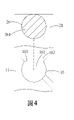
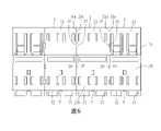
當第一光纖適配器1及第二光纖適配器2相組裝時,將第一光纖適配器1的第一側壁面11a對接於第二光纖適配器2的第一側壁面21a,使第一座體11之多個第一滑移部15由下向上分別與多個第二滑移部25相結合(如圖3所示),使第一卡扣部16由下向上與第二卡扣部26相結合並到達定位(如圖4與圖5所示),第一光纖適配器1及第二光纖適配器2組成拼接式光纖適配器組(如圖6所示),通過拼接多個光纖適配器增加容置槽(孔數),提高光纖適配器組的適用性。When the first
請同時參閱圖2,在一些實施例中,第一座體11與第二座體21為長矩形的中空殼體,為射出成型成一體式結構,結構穩固、強度提高。Please refer to FIG. 2 at the same time. In some embodiments, the
請同時參閱圖2,在一些實施例中,第一容置槽12與第二容置槽22內設置有基座組件5,使第一容置槽12內分隔成二個容置槽(亦可無基座組件5而為單一個容置槽),使第二容置槽22內分隔成二個容置槽(亦可無基座組件5而為單一個容置槽);第一座體11兩端可進一步包括多個第一插口13,第二座體21兩端可進一步包括多個第二插口23,如四埠、八埠、十六埠、三十二埠插口等,供多個光纖連接器分別插入第一插口13與第二插口23使用。Please refer to FIG. 2 at the same time. In some embodiments, a
請同時參閱圖2與圖3,在一些實施例中,各第一滑移部15與各第二滑移部25分別為相互匹配的凹凸結構,第一滑移部15為鳩尾形狀的凹槽,第二滑移部25為鳩尾形狀的凸塊,非以此為限;在一些實施例中,第一滑移部15為鳩尾形狀的凸塊,第二滑移部25為鳩尾形狀的凹槽;在一些實施例中,各第一滑移部15與各第二滑移部25分別為T字型或葫蘆型相互匹配的凹凸結構,各第一滑移部15與各第二滑移部25相結合後避免各光纖適配器側邊受力而脫離。Please refer to FIG. 2 and FIG. 3 at the same time. In some embodiments, each first sliding
請同時參閱圖2與圖3,在一些實施例中,各第一滑移部15與各第二滑移部25彼此可為導軌型式的結構供滑移相卡掣,但非以此為限;在一些實施例中,各第一滑移部15與各第二滑移部25彼此可為干涉迫緊方式相卡掣。Please refer to FIG. 2 and FIG. 3 at the same time. In some embodiments, each first sliding
請同時參閱圖2與圖3,在一些實施例中,第一光纖適配器1的兩個第一滑移部15可分別為凹槽與凸塊,第二光纖適配器2的兩個第二滑移部25可分別為凹槽與凸塊,各凹槽與各凸塊相對應匹配。Please refer to FIG. 2 and FIG. 3 at the same time. In some embodiments, the two first sliding
請同時參閱圖4與圖5,在一些實施例中,第一卡扣部16與第二卡扣部26分別為相互匹配的凹凸結構,在一些實施例中,第一卡扣部16為凹槽(可為圓形、方形或其他幾何形狀),第二卡扣部26為凸塊(可為圓形、方形或其他幾何形狀),非以此為限;在一些實施例中,第一卡扣部16為凸塊,第二卡扣部26為凹槽;在一些實施例中,第一卡扣部16具有凹槽161及插入口162,插入口162兩側具有扣合部163,第二卡扣部26具有凸塊261,凸塊261由插入口162扣入於凹槽161內,各扣合部163接觸於凸塊261限位,使第一卡扣部16與第二卡扣部26相卡掣固定,使第一座體11與第二座體21相結合固定;欲將第一卡扣部16與第二卡扣部26相拆解時,使用者施予一作用力將第一座體11與第二座體21相分解,使得原卡掣固定的第一卡扣部16與第二卡扣部26脫離。Please refer to FIG. 4 and FIG. 5 at the same time. In some embodiments, the
請同時參閱圖1與圖2,在一些實施例中,第一容置槽12供光纖連接器插接之插接方向I與第二容置槽22供光纖連接器插接之插接方向I相同;各第一滑移部15沿一軸向設置於第一座體11之第一側壁面11a,軸向垂直於第一容置槽12之插接方向I,各第二滑移部25沿軸向設置於第二座體21之第一側壁面21a,軸向垂直於第二容置槽22之插接方向I。Please refer to FIG. 1 and FIG. 2 at the same time. In some embodiments, the insertion direction I of the
請同時參閱圖2與圖3,在一些實施例中,各第一滑移部15為滑槽,各第一滑移部15由第一座體11之第二側壁面11b的側端延伸設置至第一座體11之第四側壁面11d的側端,各第二滑移部25為滑塊,各第二滑移部25由第二座體21之第二側壁面21b的側端延伸設置至第二座體21之第四側壁面21d的側端。Please refer to FIG. 2 and FIG. 3 at the same time. In some embodiments, each first sliding
請同時參閱圖2與圖3,在一些實施例中,各第一滑移部15分別位於第一座體11之第一側壁面11a之二邊區域,第一卡扣部16位於多個第一滑移部15之間(第一卡扣部16亦可位於非多個第一滑移部15之間的第一座體11之第一側壁面11a的任何位置),各第二滑移部25分別位於第二座體21之第一側壁面21a之二邊區域,第二卡扣部26位於多個第二滑移部25之間(第二卡扣部26亦可位於非多個第二滑移部25之間的第二座體21之第一側壁面21a的任何位置),非以此為限;當拼接式光纖適配器組的各光纖適配器分別插接各光纖連接器與其光纖線時,各光纖線的重力會使各光纖適配器向下拉扯,使各光纖適配器受到向下拉動的力量,通過多個第一滑移部15與多個第二滑移部25相結合與第一卡扣部16與第二卡扣部26相結合的固定作用,使各光纖適配器相對接的側邊不會因為受到向下拉動的力量而使各光纖適配器彼此相脫離。Please refer to FIG. 2 and FIG. 3 at the same time. In some embodiments, each first sliding
在一些實施例中,當第一卡扣部16與第二卡扣部26相結合後,在各光纖適配器上方覆蓋一面板來壓持固定,避免第一卡扣部16與第二卡扣部26相分離。In some embodiments, after the
請同時參閱圖2與圖3,在一些實施例中,第一卡扣部16位於多個第一滑移部15之間且相鄰於多個第一滑移部15之其中之一,第二卡扣部26位於多個第二滑移部25之間且相鄰於多個第二滑移部25之其中之一;當第一光纖適配器1及第二光纖適配器2相組裝時,使第一座體11之多個第一滑移部15由下向上分別與多個第二滑移部25相結合,使第一卡扣部16由下向上與第二卡扣部26相結合並到達定位,第一卡扣部16與第二卡扣部26具有防呆功能且避免第一卡扣部16由上向下與第二卡扣部26的錯誤組裝方向,使第一卡扣部16與第二卡扣部26相結合並到達定位後,第一座體11之第二側壁面11b與第二座體21之第二側壁面21b切齊,第一座體11之第四側壁面11d與第二座體21之第四側壁面21d切齊。Please refer to FIG. 2 and FIG. 3 at the same time. In some embodiments, the
請同時參閱圖3,在一些實施例中,第一卡扣部16位於第一座體11之第一側壁面11a與第一座體11之第二側壁面11b之間,第二卡扣部26位於第二座體21之第一側壁面21a與第二座體21之第二側壁面21b之間,非以此為限。Please refer to FIG. 3 at the same time. In some embodiments, the
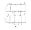
請同時參閱圖7,圖7為光纖適配器組組裝時之側視示意圖,第一卡扣部16位於第一座體11之第一側壁面11a的下方,第二卡扣部26位於第二座體21之第一側壁面21a的下方;在一些實施例中,第一卡扣部16位於第一座體11之第一側壁面11a與第一座體11之第四側壁面11d之間,第二卡扣部26位於第二座體21之第一側壁面21a與第二座體21之第四側壁面21d之間。Please refer to FIG. 7 at the same time. FIG. 7 is a schematic side view of the optical fiber adapter set when assembled. The
請同時參閱圖1與圖2,在一些實施例中,為詳細說明多個光纖適配器相互拼接的結構,以下以二個的光纖適配器(第二光纖適配器2與第三光纖適配器3)為例說明,但非不以此為限,亦可將六個或八個或十二個等數量的光纖適配器相拼接使用;在一些實施例中,第二光纖適配器2的第二座體21之第三側壁面21c與第二座體21之第一側壁面21a相對稱位於第二座體21之兩側,第二座體21之第三側壁面21c具有多個第三滑移部27及第三卡扣部28,拼接式光纖適配器組更包括第三光纖適配器3,第三光纖適配器3包括第三座體31,第三座體31由四側壁面界定有第三容置槽32,第三座體31之兩端具有連通於第三容置槽32之第三插口33,第三座體31之第一側壁面31a具有多個第四滑移部37及第四卡扣部38,各第三滑移部27與各第四滑移部37分別相結合,第三卡扣部28與第四卡扣部38相結合。Please refer to FIG. 1 and FIG. 2 at the same time. In some embodiments, in order to describe the splicing structure of multiple fiber optic adapters in detail, the following two fiber optic adapters (the second fiber optic adapter 2 and the third fiber optic adapter 3) are used as examples to illustrate , but not limited thereto, it is also possible to splice and use six or eight or twelve fiber optic adapters of the same number; in some embodiments, the third of the second base body 21 of the second fiber optic adapter 2 The side wall surface 21c is symmetrically located on both sides of the second seat body 21 with the first side wall surface 21a of the second seat body 21, and the third side wall surface 21c of the second seat body 21 has a plurality of third sliding parts 27 and third The buckle part 28, the spliced optical fiber adapter set further includes a third optical fiber adapter 3, the third optical fiber adapter 3 includes a third seat body 31, the third seat body 31 is defined by a third accommodating groove 32 by four side walls, the third Both ends of the seat body 31 have a third socket 33 connected to the third receiving groove 32, and the first side wall surface 31a of the third seat body 31 has a plurality of fourth sliding parts 37 and fourth buckling parts 38, each The third sliding part 27 is combined with each of the fourth sliding parts 37 respectively, and the third buckling part 28 is combined with the fourth buckling part 38 .
綜合上述,依據一些實施例,通過多個光纖適配器彼此並排且拼接在一塊,提供多個光纖適配器供多個光纖連接器插接,滿足光纖線靈活佈線的需求;依據一些實施例,通過多個第一滑移部與多個第二滑移部相結合與第一卡扣部與第二卡扣部相結合的固定作用,使各光纖適配器相對接的側邊不會因為各光纖線向下拉動的力量而使各光纖適配器彼此相脫離。To sum up the above, according to some embodiments, multiple fiber optic adapters are arranged side by side and spliced together to provide multiple fiber optic adapters for multiple fiber optic connectors to meet the needs of flexible wiring of optical fiber cables; The fixing effect of the combination of the first sliding part and multiple second sliding parts and the combination of the first buckle part and the second buckle part prevents the sides of the optical fiber adapters from facing downward due to the fiber optic cables. The pulling force separates the fiber optic adapters from each other.
雖然本創作以前述之較佳實施例揭露如上,然其並非用以限定本創作,任何熟習本領域技藝者,在不脫離本創作之精神和範圍內,當可作些許之更動與潤飾,因此本創作之專利保護範圍須視本說明書所附之申請專利範圍界定者為準。Although this creation is disclosed above with the above-mentioned preferred embodiments, it is not intended to limit this creation. Anyone who is familiar with the art in this field can make some changes and modifications without departing from the spirit and scope of this creation. Therefore The scope of patent protection for this creation shall be subject to the definition of the scope of patent application attached to this specification.
1:第一光纖適配器
11:第一座體
11a:第一側壁面
11b:第二側壁面
11c:第三側壁面
11d:第四側壁面
12:第一容置槽
13:第一插口
15:第一滑移部
16:第一卡扣部
161:凹槽
162:插入口
163:扣合部
2:第二光纖適配器
21:第二座體
21a:第一側壁面
21b:第二側壁面
21c:第三側壁面
21d:第四側壁面
22:第二容置槽
23:第二插口
25:第二滑移部
26:第二卡扣部
261:凸塊
27:第二滑移部
28:第三卡扣部
3:第三光纖適配器
31:第三座體
31a:第一側壁面
32:第三容置槽
33:第三插口
37:第四滑移部
38:第四卡扣部
5:基座組件
I:插接方向1: First fiber optic adapter
11: The
圖1繪示依據一些實施例,光纖適配器組之外觀示意圖; 圖2繪示依據一些實施例,光纖適配器組之分解示意圖; 圖3繪示依據一些實施例,光纖適配器組組裝時之側視示意圖,第一卡扣部位於第一座體之第一側壁面的上方,第二卡扣部位於第二座體之第一側壁面的上方; 圖4繪示依據一些實施例,第一卡扣部與第二卡扣部組裝時之放大示意圖; 圖5繪示依據一些實施例,第一卡扣部與第二卡扣部組裝後之放大示意圖; 圖6繪示依據一些實施例,光纖適配器組之俯視示意圖;及 圖7繪示依據一些實施例,光纖適配器組組裝時之側視示意圖,第一卡扣部位於第一座體之第一側壁面的下方,第二卡扣部位於第二座體之第一側壁面的下方。 Fig. 1 shows a schematic diagram of the appearance of an optical fiber adapter set according to some embodiments; FIG. 2 shows an exploded view of a fiber optic adapter set according to some embodiments; Fig. 3 shows a schematic side view of an optical fiber adapter set assembled according to some embodiments. above the side walls; FIG. 4 shows an enlarged schematic view of the assembly of the first buckle part and the second buckle part according to some embodiments; FIG. 5 is an enlarged schematic diagram of the assembled first buckle part and the second buckle part according to some embodiments; 6 illustrates a schematic top view of a fiber optic adapter set, according to some embodiments; and 7 shows a schematic side view of an optical fiber adapter set assembled according to some embodiments. The first buckle part is located below the first side wall of the first base, and the second buckle part is located on the first side wall of the second base. below the side wall.
1:第一光纖適配器 1: First fiber optic adapter
11:第一座體 11: The first body
11a:第一側壁面 11a: first side wall surface
11b:第二側壁面 11b: Second side wall surface
11c:第三側壁面 11c: The third side wall
11d:第四側壁面 11d: the fourth side wall
12:第一容置槽 12: The first storage tank
13:第一插口 13: The first socket
15:第一滑移部 15: The first sliding part
16:第一卡扣部 16: The first buckle part
2:第二光纖適配器 2: Second fiber optic adapter
21:第二座體 21: The second seat body
21a:第一側壁面 21a: first side wall surface
21b:第二側壁面 21b: second side wall surface
21c:第三側壁面 21c: The third side wall
21d:第四側壁面 21d: The fourth side wall
22:第二容置槽 22: The second storage tank
23:第二插口 23: Second socket
25:第二滑移部 25: The second sliding part
26:第二卡扣部 26: The second buckle part
27:第二滑移部 27: The second sliding part
28:第三卡扣部 28: The third buckle part
3:第三光纖適配器 3: The third fiber optic adapter
31:第三座體 31: The third body
31a:第一側壁面 31a: first side wall surface
32:第三容置槽 32: The third storage tank
33:第三插口 33: The third socket
37:第四滑移部 37: The fourth sliding part
38:第四卡扣部 38: The fourth buckle part
5:基座組件 5: Base assembly
Claims (10)
Applications Claiming Priority (2)
| Application Number | Priority Date | Filing Date | Title |
|---|---|---|---|
| CN202221422828.2 | 2022-06-09 | ||
| CN202221422828.2U CN217639647U (en) | 2022-06-09 | 2022-06-09 | Spliced optical fiber adapter set |
Publications (1)
| Publication Number | Publication Date |
|---|---|
| TWM635667U true TWM635667U (en) | 2022-12-21 |
Family
ID=83624252
Family Applications (2)
| Application Number | Title | Priority Date | Filing Date |
|---|---|---|---|
| TW111207230U TWM635667U (en) | 2022-06-09 | 2022-07-06 | Assembly-type fiber optic adapter set |
| TW112203675U TWM645624U (en) | 2022-06-09 | 2023-04-19 | Assembly-type fiber optic adapter set |
Family Applications After (1)
| Application Number | Title | Priority Date | Filing Date |
|---|---|---|---|
| TW112203675U TWM645624U (en) | 2022-06-09 | 2023-04-19 | Assembly-type fiber optic adapter set |
Country Status (2)
| Country | Link |
|---|---|
| CN (1) | CN217639647U (en) |
| TW (2) | TWM635667U (en) |
Families Citing this family (1)
| Publication number | Priority date | Publication date | Assignee | Title |
|---|---|---|---|---|
| CN118818672A (en) * | 2023-04-19 | 2024-10-22 | 连讯通信(天津)有限公司 | Splice Fiber Optic Adapter Set |
-
2022
- 2022-06-09 CN CN202221422828.2U patent/CN217639647U/en active Active
- 2022-07-06 TW TW111207230U patent/TWM635667U/en unknown
-
2023
- 2023-04-19 TW TW112203675U patent/TWM645624U/en unknown
Also Published As
| Publication number | Publication date |
|---|---|
| CN217639647U (en) | 2022-10-21 |
| TWM645624U (en) | 2023-09-01 |
Similar Documents
| Publication | Publication Date | Title |
|---|---|---|
| JP2860469B2 (en) | Adapter assembly for optical fiber connector | |
| US8641293B2 (en) | Optical fiber connector and apparatus of facilitating to pull out optical fiber connector | |
| CN202600189U (en) | Adapter assembly and connector assembly | |
| US8821036B2 (en) | Optical module and optical system | |
| JP2024155795A (en) | Connector-type optical fiber adapter set | |
| JP4514004B2 (en) | Optical interconnect assembly | |
| US20160313512A1 (en) | Stackable optical fiber adapter | |
| JPH0560939A (en) | Optical connection means | |
| JPH06100698B2 (en) | Optical fiber connector assembly | |
| KR100304505B1 (en) | Optical fiber connector assembly | |
| TWM635667U (en) | Assembly-type fiber optic adapter set | |
| US20230139027A1 (en) | Power and/or data connectivity track system | |
| JP2001350059A (en) | Reversible connector equipped with separating tab | |
| TWM561952U (en) | Optical fiber connection devices | |
| TWM598955U (en) | Optical fiber connection device | |
| CN220105344U (en) | Spliced optical fiber adapter group | |
| JP7659010B2 (en) | Connector-type optical fiber adapter set | |
| TWM645623U (en) | Assembly-type fiber optic adapter set | |
| CN219799842U (en) | Spliced optical fiber adapter group | |
| CN118818671A (en) | Splice Fiber Optic Adapter Set | |
| JPH0583709U (en) | 2-fiber optical connector | |
| KR200257489Y1 (en) | Adapter for interconnecting optical fiber connectors | |
| CN113866904A (en) | Optical fiber connecting device and network equipment | |
| US20250370194A1 (en) | Optical fiber connector | |
| JP2026031535A (en) | Modular Multimodal Connector Housing |