TWI889432B - Detachably supporting mechanism and reticle pod with the same - Google Patents
Detachably supporting mechanism and reticle pod with the same Download PDFInfo
- Publication number
- TWI889432B TWI889432B TW113124903A TW113124903A TWI889432B TW I889432 B TWI889432 B TW I889432B TW 113124903 A TW113124903 A TW 113124903A TW 113124903 A TW113124903 A TW 113124903A TW I889432 B TWI889432 B TW I889432B
- Authority
- TW
- Taiwan
- Prior art keywords
- mounting hole
- support member
- base
- protrusion
- supporting
- Prior art date
Links
Images




Classifications
-
- H—ELECTRICITY
- H10—SEMICONDUCTOR DEVICES; ELECTRIC SOLID-STATE DEVICES NOT OTHERWISE PROVIDED FOR
- H10P—GENERIC PROCESSES OR APPARATUS FOR THE MANUFACTURE OR TREATMENT OF DEVICES COVERED BY CLASS H10
- H10P72/00—Handling or holding of wafers, substrates or devices during manufacture or treatment thereof
- H10P72/10—Handling or holding of wafers, substrates or devices during manufacture or treatment thereof using carriers specially adapted therefor, e.g. front opening unified pods [FOUP]
- H10P72/19—Handling or holding of wafers, substrates or devices during manufacture or treatment thereof using carriers specially adapted therefor, e.g. front opening unified pods [FOUP] closed carriers
- H10P72/1906—Handling or holding of wafers, substrates or devices during manufacture or treatment thereof using carriers specially adapted therefor, e.g. front opening unified pods [FOUP] closed carriers specially adapted for containing masks, reticles or pellicles
-
- G—PHYSICS
- G02—OPTICS
- G02B—OPTICAL ELEMENTS, SYSTEMS OR APPARATUS
- G02B27/00—Optical systems or apparatus not provided for by any of the groups G02B1/00 - G02B26/00, G02B30/00
- G02B27/32—Fiducial marks and measuring scales within the optical system
-
- G—PHYSICS
- G03—PHOTOGRAPHY; CINEMATOGRAPHY; ANALOGOUS TECHNIQUES USING WAVES OTHER THAN OPTICAL WAVES; ELECTROGRAPHY; HOLOGRAPHY
- G03F—PHOTOMECHANICAL PRODUCTION OF TEXTURED OR PATTERNED SURFACES, e.g. FOR PRINTING, FOR PROCESSING OF SEMICONDUCTOR DEVICES; MATERIALS THEREFOR; ORIGINALS THEREFOR; APPARATUS SPECIALLY ADAPTED THEREFOR
- G03F1/00—Originals for photomechanical production of textured or patterned surfaces, e.g., masks, photo-masks, reticles; Mask blanks or pellicles therefor; Containers specially adapted therefor; Preparation thereof
- G03F1/66—Containers specially adapted for masks, mask blanks or pellicles; Preparation thereof
-
- H—ELECTRICITY
- H10—SEMICONDUCTOR DEVICES; ELECTRIC SOLID-STATE DEVICES NOT OTHERWISE PROVIDED FOR
- H10P—GENERIC PROCESSES OR APPARATUS FOR THE MANUFACTURE OR TREATMENT OF DEVICES COVERED BY CLASS H10
- H10P72/00—Handling or holding of wafers, substrates or devices during manufacture or treatment thereof
- H10P72/10—Handling or holding of wafers, substrates or devices during manufacture or treatment thereof using carriers specially adapted therefor, e.g. front opening unified pods [FOUP]
- H10P72/19—Handling or holding of wafers, substrates or devices during manufacture or treatment thereof using carriers specially adapted therefor, e.g. front opening unified pods [FOUP] closed carriers
- H10P72/1902—Handling or holding of wafers, substrates or devices during manufacture or treatment thereof using carriers specially adapted therefor, e.g. front opening unified pods [FOUP] closed carriers specially adapted for a single substrate
-
- H—ELECTRICITY
- H10—SEMICONDUCTOR DEVICES; ELECTRIC SOLID-STATE DEVICES NOT OTHERWISE PROVIDED FOR
- H10P—GENERIC PROCESSES OR APPARATUS FOR THE MANUFACTURE OR TREATMENT OF DEVICES COVERED BY CLASS H10
- H10P72/00—Handling or holding of wafers, substrates or devices during manufacture or treatment thereof
- H10P72/10—Handling or holding of wafers, substrates or devices during manufacture or treatment thereof using carriers specially adapted therefor, e.g. front opening unified pods [FOUP]
- H10P72/19—Handling or holding of wafers, substrates or devices during manufacture or treatment thereof using carriers specially adapted therefor, e.g. front opening unified pods [FOUP] closed carriers
- H10P72/1911—Handling or holding of wafers, substrates or devices during manufacture or treatment thereof using carriers specially adapted therefor, e.g. front opening unified pods [FOUP] closed carriers characterised by materials, roughness, coatings or the like
-
- H—ELECTRICITY
- H10—SEMICONDUCTOR DEVICES; ELECTRIC SOLID-STATE DEVICES NOT OTHERWISE PROVIDED FOR
- H10P—GENERIC PROCESSES OR APPARATUS FOR THE MANUFACTURE OR TREATMENT OF DEVICES COVERED BY CLASS H10
- H10P72/00—Handling or holding of wafers, substrates or devices during manufacture or treatment thereof
- H10P72/10—Handling or holding of wafers, substrates or devices during manufacture or treatment thereof using carriers specially adapted therefor, e.g. front opening unified pods [FOUP]
- H10P72/19—Handling or holding of wafers, substrates or devices during manufacture or treatment thereof using carriers specially adapted therefor, e.g. front opening unified pods [FOUP] closed carriers
- H10P72/1922—Handling or holding of wafers, substrates or devices during manufacture or treatment thereof using carriers specially adapted therefor, e.g. front opening unified pods [FOUP] closed carriers characterised by the construction of the closed carrier
Landscapes
- Physics & Mathematics (AREA)
- General Physics & Mathematics (AREA)
- Optics & Photonics (AREA)
- Container, Conveyance, Adherence, Positioning, Of Wafer (AREA)
- Preparing Plates And Mask In Photomechanical Process (AREA)
- Snaps, Bayonet Connections, Set Pins, And Snap Rings (AREA)
- Connection Of Plates (AREA)
- Exposure Of Semiconductors, Excluding Electron Or Ion Beam Exposure (AREA)
Abstract
Description
本發明係有關一種光罩盒的支撐機構,特別是指具有可拆式支撐結構的支撐機構。The present invention relates to a support mechanism for a mask box, and in particular to a support mechanism with a detachable support structure.
在習知的極紫外光(EUV)光罩傳送盒中透過支撐機構來支撐光罩,支撐機構包括支撐件以及限位柱。其中支撐件用於承載並接觸光罩,且限位柱及支撐件為一體式。當支撐機構組合於光罩盒的内盒基座時,除了透過螺絲進行固定外,還會使用滾花銷鉚入限位柱內部加強固定以避免鬆脫。因為滾花銷與限位柱內部為干涉配合,因此,若需要將習知的支撐結構進行更換時,需要先破壞限位柱後,並拆除螺絲,再將滾花銷敲擊出來。In the known extreme ultraviolet (EUV) mask transfer box, the mask is supported by a support mechanism, which includes a support member and a limit column. The support member is used to carry and contact the mask, and the limit column and the support member are integrated. When the support mechanism is assembled to the inner box base of the mask box, in addition to being fixed by screws, a knives pin is also used to be riveted into the inside of the limit column to strengthen the fixation to avoid loosening. Because the knives pin and the inside of the limit column are interference fit, if the known support structure needs to be replaced, it is necessary to first destroy the limit column, remove the screws, and then knock out the knives pin.
然而,在實際使用過程中,只有支撐件會跟光罩接觸,限位柱只是避免突發狀況時,不正常的作動錯誤傷到光罩的元件,因此正常情況下光罩並不會與限位柱接觸。換言之,僅有支撐件為消耗品,限位柱實際上並不需要更換。但是因為現行的設計,支撐件若需更換,限位柱會連同支撐件一起被汰換掉,導致材料以及成本上的浪費,並且還有拆除不便的問題。However, in actual use, only the support parts will contact the photomask, and the limit posts are only used to prevent abnormal actuation errors from damaging the photomask components in unexpected situations. Therefore, the photomask will not contact the limit posts under normal circumstances. In other words, only the support parts are consumables, and the limit posts do not actually need to be replaced. However, due to the current design, if the support parts need to be replaced, the limit posts will be replaced together with the support parts, resulting in waste of materials and costs, and the problem of inconvenience in removal.
有鑑於上述先前技術的問題,本發明提供可拆式支撐結構,來簡化支撐機構的拆卸過程,並且降低材料及成本上的浪費。此外,支撐件可根據實際需求選用更耐磨的材料來加強使用壽命。In view of the above problems of the prior art, the present invention provides a detachable support structure to simplify the disassembly process of the support mechanism and reduce the waste of materials and costs. In addition, the support member can be made of a more wear-resistant material according to actual needs to enhance the service life.
本發明提供一種光罩盒,其適用於雙層盒,包括外盒及其收容之一內盒,該內盒包括:一基座、以及至少一支撐機構,設置於該基座上;該支撐機構包括:一支撐組件,連接於該基座的一安裝介面,該支撐組件包括一座體、至少一個限位柱、以及一安裝孔,該至少一個限位柱與該座體連接,該安裝孔貫穿該座體且非圓形孔;以及一支撐件,具有用於配合該安裝孔的一匹配結構,使該支撐件可拆卸地容置於該安裝孔中。The present invention provides a mask box, which is suitable for a double-layer box, including an outer box and an inner box contained therein, wherein the inner box includes: a base, and at least one supporting mechanism, which is arranged on the base; the supporting mechanism includes: a supporting assembly, which is connected to an installation interface of the base, and the supporting assembly includes a seat body, at least one limiting column, and a mounting hole, the at least one limiting column is connected to the seat body, and the mounting hole passes through the seat body and is a non-circular hole; and a supporting piece, which has a matching structure for matching the mounting hole, so that the supporting piece can be detachably accommodated in the mounting hole.
在一具體實施例中,該支撐件具有至少一個抗自轉特徵,當該支撐件設置於該安裝孔時,該至少一個抗自轉特徵抵持該安裝孔的邊緣。In a specific embodiment, the support member has at least one anti-rotation feature, and when the support member is disposed in the mounting hole, the at least one anti-rotation feature abuts against the edge of the mounting hole.
在一具體實施例中,該抗自轉特徵的厚度與該座體的厚度相同或近似。In one embodiment, the thickness of the anti-rotation feature is the same as or similar to the thickness of the base.
在一具體實施例中,該支撐件包括一接觸部、一頸部、以及一底部,該接觸部及該底部藉由該頸部連接,該頸部具有該至少一個抗自轉特徵。In a specific embodiment, the support member includes a contact portion, a neck portion, and a bottom portion, the contact portion and the bottom portion are connected via the neck portion, and the neck portion has the at least one anti-rotation feature.
在一具體實施例中,該支撐件包括一接觸部、一頸部、以及一底部,該底部設有至少一個凸部,該至少一個凸部自該底部向外突出;該安裝孔設有至少一個缺口,該至少一個缺口對應該至少一個凸部的形狀自該安裝孔的周緣向外延伸。In a specific embodiment, the support member includes a contact portion, a neck portion, and a bottom portion, wherein the bottom portion is provided with at least one protrusion, and the at least one protrusion protrudes outward from the bottom portion; the mounting hole is provided with at least one notch, and the at least one notch extends outward from the periphery of the mounting hole corresponding to the shape of the at least one protrusion.
在一具體實施例中,該頸部設有至少一個抗自轉特徵,該安裝孔設有至少一定位凸部,該定位凸部自該安裝孔的該周緣向內突出,該定位凸部抵持該至少一個抗自轉特徵,以避免該支撐件相對支撐組件旋轉。In a specific embodiment, the neck is provided with at least one anti-rotation feature, and the mounting hole is provided with at least one positioning protrusion, which protrudes inward from the periphery of the mounting hole, and the positioning protrusion abuts against the at least one anti-rotation feature to prevent the support member from rotating relative to the support assembly.
在一具體實施例中,該至少一個抗自轉特徵為自該頸部表面向外延伸的一抵持凸部,該頸部的該抵持凸部與該底部的該至少一個凸部在垂直方向上錯位。In a specific embodiment, the at least one anti-rotation feature is a supporting protrusion extending outward from the surface of the neck, and the supporting protrusion of the neck and the at least one protrusion of the bottom are misaligned in the vertical direction.
在一具體實施例中,該底部具有至少一個凹口,該至少一個凹口自該底部表面的徑向方向向內凹進,使該支撐件放入該安裝孔時,該底部避開該安裝孔的該定位凸部。In a specific embodiment, the bottom has at least one notch, and the at least one notch is recessed inward from the radial direction of the bottom surface, so that when the support member is placed in the mounting hole, the bottom avoids the positioning protrusion of the mounting hole.
在一具體實施例中,該至少一個凹口與該至少一個凸部相鄰地設置。In a specific embodiment, the at least one recess is disposed adjacent to the at least one protrusion.
在一具體實施例中,該支撐件包括一固定孔,該固定孔設置於該底部及該頸部內,該支撐件被旋轉至該抵持凸部與該定位凸部相互抵持的一定位位置後,藉由一固定元件與該固定孔的配合,完成該支撐件的安裝。In a specific embodiment, the support member includes a fixing hole, which is arranged in the bottom and the neck. After the support member is rotated to a positioning position where the supporting protrusion and the positioning protrusion abut against each other, the support member is installed by cooperating with a fixing element and the fixing hole.
在一具體實施例中,當該支撐件位於該定位位置時,該接觸部的下表面與該座體的上表面接觸,該底部的上表面與該座體的下表面接觸。In a specific embodiment, when the supporting member is located at the positioning position, the lower surface of the contact portion contacts the upper surface of the base, and the upper surface of the bottom contacts the lower surface of the base.
在一具體實施例中,構成該支撐件及該支撐組件的材料不同。In one embodiment, the materials constituting the support member and the support assembly are different.
在一具體實施例中,該支撐件的材料的玻璃轉化溫度大於或等於200℃(392℉)以上。In one embodiment, the material of the support has a glass transition temperature greater than or equal to 200°C (392°F).
請參閱圖1,本發明提供一種具有可拆式支撐機構的光罩盒,其適用於雙層盒,包括外盒以及收容於外盒中的内盒,内盒包括基座10、蓋體(圖未示),以及支撐機構20,其連接於基座10的安裝介面101,支撐機構20用於承載光罩。Please refer to Figure 1. The present invention provides a mask box with a detachable supporting mechanism, which is suitable for a double-layer box, including an outer box and an inner box accommodated in the outer box. The inner box includes a
請參閱圖2,圖2為圖1圓圈A處的放大分解圖。本發明第一實施例的可拆式支撐機構20包括支撐組件21、及支撐件23。支撐組件21設置於基座10的安裝介面101中,支撐件23具有用於配合支撐組件21的安裝孔213的匹配結構23A,使支撐件23可拆卸地容置於於支撐組件21的安裝孔213中。Please refer to FIG. 2, which is an enlarged exploded view of the circle A in FIG. 1. The
請參閱圖4A至圖4C,支撐件23具有接觸部231、固定孔234、及匹配結構23A。接觸部231可用於讓使用者握持或轉動支撐件23,固定孔234貫穿匹配結構23A,請同時參閱圖3,匹配結構23A可穿過安裝孔213並且可部分地抵持於安裝孔213,使支撐件可容置於安裝孔213中。本實施例中,匹配結構23A包括頸部232、以及底部233。接觸部231及底部233藉由頸部232連接,固定孔234設置於底部233及頸部232內。本實施例中,固定孔234自底部233的下表面2337貫穿並完全地或部分地延伸至頸部232。較佳地,接觸部231的上表面用於與光罩直接接觸,頸部232自接觸部231的下表面2315延伸,且自底部233的上表面2335延伸。較佳地,接觸部231的上表面形成有複數個接觸凸起2311,來減少乘載光罩時光罩及支撐件23的接觸面積。Please refer to FIG. 4A to FIG. 4C , the
底部233的周緣具有至少一個凸部2331、以及至少一個凹口2333,凸部2331相對於底部233表面的徑向方向向外突出,凹口2333相對於底部233表面的徑向方向向內凹進,至少一個凸部2331與至少一個凹口2333相鄰地設置。較佳地,底部233具有一個中心O1,凸部2331到中心O1的距離R1大於凹口2333到中心O1的距離p1。本發明實施例中,底部233的周緣具有四個凸部2331、以及四個凹口2333。The periphery of the
進一步參閱圖4B及圖4C,頸部232具有至少一個抵持凸部2321(或可稱為抗自轉特徵),其從頸部232的表面沿徑向方向向外突出,從前視方向來看,頸部232具有厚度d1。厚度d1亦可為接觸部231的下表面2315至底部233的上表面2335之間的垂直距離。凸部2331離底部233的中心O1的最遠距離R1界定有垂直方向Y1,以抵持凸部2321離底部233的中心O1的最短距離p1界定有垂直方向Y2,凸部2331及抵持凸部2321在垂直方向上錯位,即垂直方向Y1與垂直方向Y2彼此平行但不重疊。Referring to FIG. 4B and FIG. 4C , the
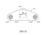
請參閱圖5A及圖5B,支撐組件21具有座體211、至少一個限位柱212、以及安裝孔213。至少一個限位柱212與座體211連接,至少一個限位柱212內部設有固定孔2121。安裝孔213貫穿座體211且非圓形孔,支撐件23的匹配結構23A與安裝孔213的形狀匹配,讓支撐件23可拆卸地安裝於安裝孔213中。從支撐組件21的前視方向來看,座體211具有一個厚度D1,厚度D1與支撐件23的頸部232的厚度d1實質相同或近似。Please refer to FIG. 5A and FIG. 5B , the
安裝孔213的周緣具有至少一個缺口2131、以及至少一個定位凸部2133,缺口2131相對於安裝孔213的徑向方向向外延伸,定位凸部2133相對於安裝孔213的徑向方向向內凹進,其中至少一個缺口2131與至少一個定位凸部2133相鄰設置。使當支撐件組合於支撐組件上時,缺口2131可避讓支撐件23的匹配結構23A,並且透過定位凸部2133來與支撐件23的匹配結構23A抵持以相互定位,以避免組裝時支撐件23的不必要的自轉。The periphery of the
本實施例中,支撐件23組合於支撐組件21上時避讓支撐件23的凸部2331,且支撐件23的凹口2333可避讓定位凸部2133。當支撐件23組合於支撐組件21上時,定位凸部2133與支撐件23的抵持凸部2321相互定位。本實施例中,安裝孔213具有一個中心O2,缺口2131至中心O2的距離R2大於定位凸部2133至中心O2的距離p2。較佳地,缺口2131具有與凸部2331有相對應形狀,定位凸部2133具有與凹口2333有相對應形狀。較佳地,缺口2131至中心O2距離R2大於等於凸部2331到中心O1的距離R1。本實施例中,安裝孔213的周緣具有四個缺口2131、以及四個定位凸部2133。In this embodiment, when the
請參閱圖6A及圖6B,為更明確說明支撐件23與支撐組件21的相對位置,圖式中省略基座10。當支撐件23容置於支撐組件21時,使用者可直接握持或透過機械手臂握持支撐件23的接觸部231,將支撐件23的凸部2331與安裝孔213的缺口2131對齊並放入安裝孔213中,直到接觸部231的下表面與座體211的上表面2115互相接觸。此時接觸部231位於座體211的上表面2115以上的位置,底部233位於座體211的下表面2117以下的位置,頸部232容置在安裝孔213內。併參閱圖8A,圖8A為圖6A的B平面的剖面圖,此時抵持凸部2321與定位凸部2133並不相互接觸。Please refer to FIG. 6A and FIG. 6B . To more clearly illustrate the relative position of the
接著請參閱圖7A及圖7B,將支撐件23往一方向旋轉後,凸部2331與缺口2131相互在垂直方向上錯位,使底部233的上表面與座體211的下表面接觸,來避免支撐件23從垂直方向脫離。併參閱圖8B,圖8B為圖7A的C平面的剖面圖,轉動支撐件23直到抵持凸部2321與定位凸部2133相互抵持,使支撐件23位於定位位置後,透過安裝元件24從基座10的下方鎖固支撐件23,使支撐件23安裝至設置於基座10的支撐組件21中,即完成支撐機構20的安裝。藉由抵持凸部2321與定位凸部2133相互抵持,可避免安裝元件24鎖固支撐件23的過程中,支撐件23相對於支撐組件21旋轉。較佳地,從支撐件23的中心O1到抵持凸部2321的距離t1大於支撐件23的中心O1到定位凸部2133的距離p2,使安裝孔213的定位凸部2133能抵持著支撐件23來防止支撐件23相對支撐組件21轉動。本實施例中,安裝元件24為螺絲,而固定孔234為與該螺絲對應的螺孔。支撐件23旋轉至抵持凸部2321與定位凸部2133相互抵持的方向與安裝元件24鎖固支撐件23的方向相同,使當鎖固支撐件23時,迫使抵持凸部2321和定位凸部2133會持續接觸,來避免支撐件23在鎖固過程中產生不必要的自轉,以增加安裝效率。Next, please refer to FIG. 7A and FIG. 7B . After the
以下將說明發明可拆式支撐機構安裝於基座的安裝介面的流程。首先,請參閱圖2及圖5A,先將支撐組件21藉由固定元件22從基座10的通孔102與限位柱212內的固定孔2121進行固定,固定元件22可為利用滾花銷鉚入限位柱212或透過螺絲鎖固。The following will describe the process of installing the detachable support mechanism of the invention on the installation interface of the base. First, please refer to Figure 2 and Figure 5A, first fix the
其次,請參閱圖6A及圖6B,將支撐件23的凸部2331與安裝孔213的缺口2131對齊並放入安裝孔213中,直到接觸部231的下表面2315與座體211的上表面2115互相接觸。Next, referring to FIG. 6A and FIG. 6B , align the
接著,請參閱圖7A及圖7B,往一方向旋轉支撐件23,支撐件23的凸部2331與安裝孔213的缺口2131在垂直方向上錯位,使底部233的上表面2335與座體211的下表面2117互相接觸。併參閱圖8B,旋轉支撐件23直到定位凸部2133與抵持凸部2321接觸,使支撐件23到達定位位置。Next, please refer to FIG. 7A and FIG. 7B , the
最後,透過安裝元件24由基座的通孔103下方來鎖固支撐件23,即完成支撐機構20的安裝。支撐件23設置於安裝孔213時,可迫使抵持凸部2321持續抵持著安裝孔213的定位凸部2133,可避免支撐件23在安裝過程中相對於支撐組件21自轉。Finally, the
當欲更換支撐件23時,先移除安裝元件24,接著旋轉支撐件32直到支撐件23的凸部2331與安裝孔213的缺口2131對齊,以從安裝孔213中取出支撐件23,接著重複前述步驟即可更換支撐件23。When the
本發明第二實施例的支撐機構請參閱圖9,第二實施例與第一實施例差異在於支撐件33以及支撐組件31的結構。Please refer to FIG. 9 for the supporting mechanism of the second embodiment of the present invention. The difference between the second embodiment and the first embodiment lies in the structure of the supporting
第二實施例的可拆式支撐機構包括支撐組件31、及支撐件33。支撐組件31設置於基座10的安裝介面101,支撐件33可拆卸地安裝於支撐組件31。The detachable supporting mechanism of the second embodiment includes a supporting
請參閱圖11A及11B,支撐件33包括本體331、匹配結構33A、及固定孔(圖未示)。本體331大致上為圓柱形,其上表面形成有複數個接觸凸起3311,來減少乘載光罩時光罩及支撐件33的接觸面積。匹配結構33A用於配合支撐組件31的安裝孔313,使支撐件33容置於於支撐組件31的安裝孔313中。本實施例中,匹配結構33A具有自本體331向外突出的抗自轉特徵332,從側視方向來看抗自轉特徵332具有厚度d2。固定孔形成於本體331內,部分地貫穿本體331。Please refer to Figures 11A and 11B. The
請參閱圖12A及12B,支撐組件31具有座體311、至少一個限位柱312、以及安裝孔313。至少一個限位柱312與座體311連接,至少一個限位柱312內部設有固定孔(同第一實施例固定孔2121)。安裝孔213貫穿座體311,且為非圓形孔。抗自轉特徵332的截面形狀與安裝孔313的形狀相配合,使支撐件33可容置於安裝孔313中,並且可抵持著安裝孔313防止支撐件33自轉。從支撐組件31的前視方向來看,座體311具有厚度D2,厚度D2與支撐件33的抗自轉特徵332的厚度d2實質相同或近似。Please refer to Figures 12A and 12B. The
以下將說明本發明第二實施例可拆式支撐機構安裝於基座10的流程。請參閱圖10,首先,先將支撐組件31藉由固定元件22從下蓋的通孔102與限位柱312內的固定孔2121進行固定,固定元件22可為利用滾花銷鉚入限位柱312或透過螺絲鎖固。The following will describe the process of installing the detachable support mechanism of the second embodiment of the present invention on the
接著,使用者可直接握持或透過機械手臂握持支撐件33的匹配結構33A與安裝孔313對齊並放入安裝孔313中。接著,透過安裝元件24由基座的通孔103下方來安裝支撐件33,即完成支撐機構的安裝。透過抗自轉特徵332的截面形狀以及安裝孔313形狀的配合,使支撐件33設置於安裝孔313時,可迫使抗自轉特徵332持續抵持著安裝孔313的周緣,可避免支撐件33在安裝過程中相對於支撐組件31自轉。Then, the user can directly hold or use a robot arm to hold the
若需更換支撐件33,將安裝元件24移除後,即可將支撐件33垂直地移除,接著重複前述步驟即可更換支撐件33。支撐組件31固定基座10後不需拆卸及汰換,可避免材料及成本上的浪費。If the
本發明的第一實施例及第二實施例的可拆式支撐機構,透過支撐件23、33與支撐組件21、31可拆卸的設計,除了具有快速拆換功能外,在搭配及組合上的自由度更高。The detachable support mechanism of the first embodiment and the second embodiment of the present invention has a detachable design of the
較佳地,支撐組件21、31與支撐件23、33分別可選用不同材料構成,或進行不同的表面處理。例如支撐組件21、31可以使用較為節省成本的材料來製造,支撐件23、33則可根據實際的使用需求來選擇合適的材料。較佳地,支撐件23、33可選用較耐磨的材料,例如玻璃轉化溫度(glass transition temperature, Tg)為200℃(392℉)(含)以上的材料構成,且/或於一般大氣環境或是真空環境下,選用材料為絕緣材質或是具有靜電消散(如表面電阻介於10
4至10
11(Ω/sq)之間)功能之材質。
Preferably, the
較佳地,本發明實施例中支撐件23、33材質使用聚醯亞胺Polyimide(Pi)於磨耗以及使用壽命上有著大幅度的提升。此外,支撐件23、33本身的材質可以可為塑膠或是金屬,透過進行表面處理、於表面鍍層等方式進行加工。支撐件23、33選用的鍍層材質的玻璃轉化溫度為200℃(392℉)(含)以上,且/或於一般大氣環境或是真空環境下,皆可以為絕緣或是具有靜電消散之功能,來提高支撐件23、33的使用壽命。Preferably, the material of the
透過讓支撐件23、33選用更為耐磨以及性能更高之材料構成,有效提升支撐件23、33磨耗能力、使用壽命,以及降低光罩受微塵汙染的情況。By making the supporting
10:基座
101:安裝介面
102:通孔
103:通孔
20:支撐機構
21:支撐組件
211:座體
212:限位柱
2121:固定孔
213:安裝孔
2131:缺口
2133:定位凸部
22:固定元件
23:支撐件
23A:匹配結構
231:接觸部
2311:接觸凸起
2315:下表面
232:頸部
2321:抵持凸部
233:底部
2331:凸部
2333:凹口
2335:上表面
2337:下表面
234:固定孔
24:安裝元件
d1、D1、d2、D2:厚度
R1、R2、p1、p2、n1:距離
A:圓圈
B、C:平面
Y1、Y2:垂直方向
31:支撐組件
311:底座
312:限位柱
313:安裝孔
33:支撐件
33A:匹配結構
331:本體
3311:接觸凸起
332:抗自轉特徵
10: base
101: mounting interface
102: through hole
103: through hole
20: support mechanism
21: support assembly
211: base
212: limit column
2121: fixing hole
213: mounting hole
2131: notch
2133: positioning protrusion
22: fixing element
23:
參照下列圖式與說明,可更進一步理解本發明。非限制性與非窮舉性實例系參照下列圖式而描述。在圖式中的部件並非必須為實際尺寸;重點在於說明結構及原理。The present invention may be further understood with reference to the following drawings and descriptions. Non-limiting and non-exhaustive examples are described with reference to the following drawings. The components in the drawings are not necessarily to actual size; the emphasis is on illustrating the structure and principle.
圖1為設置有本發明支撐機構的内盒的基座立體圖。FIG. 1 is a three-dimensional view of the base of an inner box provided with the supporting mechanism of the present invention.
圖2為圖1中A處的支撐機構局部放大分解立體圖。FIG. 2 is a partially enlarged exploded perspective view of the support mechanism at point A in FIG. 1 .
圖3為支撐機構替換支撐件時的局部放大立體圖。FIG. 3 is a partially enlarged three-dimensional view of the supporting mechanism replacing the supporting member.
圖4A為本發明實施例的支撐件仰視圖。FIG. 4A is a bottom view of the support member according to an embodiment of the present invention.
圖4B為本發明實施例的支撐件前視圖。FIG. 4B is a front view of the support member according to an embodiment of the present invention.
圖4C為本發明實施例的支撐件三維立體圖。FIG. 4C is a three-dimensional diagram of the support member according to an embodiment of the present invention.
圖5A為本發明實施例的支撐組件仰視圖。FIG. 5A is a bottom view of the support assembly according to an embodiment of the present invention.
圖5B為本發明實施例的支撐組件前視圖。FIG. 5B is a front view of the support assembly according to an embodiment of the present invention.
圖6A為本發明實施例的支撐件位處於定位位置時,支撐機構的立體圖。FIG. 6A is a three-dimensional diagram of the support mechanism when the support member of the embodiment of the present invention is in the positioning position.
圖6B為本發明實施例的支撐件處於未處於定位位置時,支撐機構的另一角度立體圖。FIG6B is a three-dimensional view of the support mechanism from another angle when the support member of the embodiment of the present invention is not in the positioning position.
圖7A為本發明實施例的支撐件處於定位位置時,支撐機構的立體圖。FIG. 7A is a three-dimensional diagram of the support mechanism when the support member of the embodiment of the present invention is in a positioning position.
圖7B為本發明實施例的支撐件處於定位位置時,支撐機構的另一角度立體圖。FIG. 7B is a three-dimensional view of the support mechanism from another angle when the support member of the embodiment of the present invention is in the positioning position.
圖8A為圖6A中剖面B的剖面圖。FIG8A is a cross-sectional view of section B in FIG6A.
圖8B為圖7A中剖面C的剖面圖。FIG8B is a cross-sectional view of section C in FIG7A.
圖9為本發明第二實施例的支撐機構局部放大分解立體圖。FIG. 9 is a partially enlarged exploded perspective view of the support mechanism of the second embodiment of the present invention.
圖10為本發明第二實施例的支撐機構替換支撐件時的局部放大立體圖。FIG10 is a partially enlarged three-dimensional view of the supporting mechanism of the second embodiment of the present invention when replacing the supporting member.
圖11A為本發明第二實施例的支撐件側視圖。FIG. 11A is a side view of a support member of the second embodiment of the present invention.
圖11B為本發明第二實施例的支撐件俯視圖。FIG. 11B is a top view of the support member of the second embodiment of the present invention.
圖12A為本發明第二實施例的支撐組件側視圖。FIG. 12A is a side view of the support assembly of the second embodiment of the present invention.
圖12B為本發明第二實施例的支撐組件俯視圖。FIG. 12B is a top view of the support assembly of the second embodiment of the present invention.
10:基座 10: Base
101:安裝介面 101: Installation interface
103:通孔 103:Through hole
21:支撐組件 21: Support assembly
211:座體 211: Seat
212:限位柱 212: Limiting column
213:安裝孔 213: Mounting hole
23:支撐件 23: Support parts
23A:匹配結構 23A: Matching structure
24:安裝元件 24: Install components
Claims (12)
Applications Claiming Priority (2)
| Application Number | Priority Date | Filing Date | Title |
|---|---|---|---|
| US202363546941P | 2023-11-02 | 2023-11-02 | |
| US63/546,941 | 2023-11-02 |
Publications (2)
| Publication Number | Publication Date |
|---|---|
| TW202519975A TW202519975A (en) | 2025-05-16 |
| TWI889432B true TWI889432B (en) | 2025-07-01 |
Family
ID=93741216
Family Applications (1)
| Application Number | Title | Priority Date | Filing Date |
|---|---|---|---|
| TW113124903A TWI889432B (en) | 2023-11-02 | 2024-07-03 | Detachably supporting mechanism and reticle pod with the same |
Country Status (7)
| Country | Link |
|---|---|
| US (1) | US20250147332A1 (en) |
| JP (1) | JP7852012B2 (en) |
| KR (1) | KR20250064645A (en) |
| CN (1) | CN119937237A (en) |
| DE (1) | DE102024131211A1 (en) |
| NL (1) | NL2038899B1 (en) |
| TW (1) | TWI889432B (en) |
Families Citing this family (2)
| Publication number | Priority date | Publication date | Assignee | Title |
|---|---|---|---|---|
| TWD214306S (en) * | 2021-07-02 | 2021-09-21 | 家登精密工業股份有限公司 | Support for lower cover of reticle box |
| TW202536531A (en) * | 2024-02-13 | 2025-09-16 | 美商恩特葛瑞斯股份有限公司 | Reticle constraint for a reticle container |
Citations (4)
| Publication number | Priority date | Publication date | Assignee | Title |
|---|---|---|---|---|
| US20060087639A1 (en) * | 2002-02-22 | 2006-04-27 | Asml Holding N.V. | System and method for using a two part cover for and a box for protecting a reticle |
| TW201736945A (en) * | 2016-04-08 | 2017-10-16 | 恩特葛瑞斯股份有限公司 | Substrate container |
| CN111290215A (en) * | 2018-12-06 | 2020-06-16 | 家登精密工业股份有限公司 | Light shield container |
| TW202230022A (en) * | 2021-01-28 | 2022-08-01 | 家登精密工業股份有限公司 | Reticle pod with quickly assembling support mechanism |
Family Cites Families (8)
| Publication number | Priority date | Publication date | Assignee | Title |
|---|---|---|---|---|
| JP5198361B2 (en) | 2009-06-04 | 2013-05-15 | トヨタ自動車株式会社 | Retainer structure |
| TWI378887B (en) * | 2009-12-29 | 2012-12-11 | Gudeng Prec Industral Co Ltd | Reticle pod and supporting components therebetween |
| TWI414464B (en) * | 2011-01-11 | 2013-11-11 | 家登精密工業股份有限公司 | Extreme ultraviolet reticle storage transfer box with fixed structure |
| JP2015081947A (en) | 2013-10-21 | 2015-04-27 | レーザーテック株式会社 | Reticle container and dual pod |
| TWI623810B (en) * | 2017-01-26 | 2018-05-11 | Gudeng Precision Industrial Co., Ltd | Mask box |
| US11442370B2 (en) | 2019-10-16 | 2022-09-13 | Gudeng Precision Industrial Co., Ltd | Reticle retaining system |
| US11822257B2 (en) | 2021-03-12 | 2023-11-21 | Gudeng Precision Industrial Co., Ltd. | Reticle storage pod and method for securing reticle |
| CN219916173U (en) | 2023-05-22 | 2023-10-27 | 常州兰利电器科技有限公司 | Mask plate supporting piece and photomask box |
-
2024
- 2024-07-03 TW TW113124903A patent/TWI889432B/en active
- 2024-08-15 CN CN202411119925.8A patent/CN119937237A/en active Pending
- 2024-10-16 US US18/916,807 patent/US20250147332A1/en active Pending
- 2024-10-23 NL NL2038899A patent/NL2038899B1/en active
- 2024-10-25 DE DE102024131211.4A patent/DE102024131211A1/en active Pending
- 2024-11-01 JP JP2024193130A patent/JP7852012B2/en active Active
- 2024-11-01 KR KR1020240153407A patent/KR20250064645A/en active Pending
Patent Citations (4)
| Publication number | Priority date | Publication date | Assignee | Title |
|---|---|---|---|---|
| US20060087639A1 (en) * | 2002-02-22 | 2006-04-27 | Asml Holding N.V. | System and method for using a two part cover for and a box for protecting a reticle |
| TW201736945A (en) * | 2016-04-08 | 2017-10-16 | 恩特葛瑞斯股份有限公司 | Substrate container |
| CN111290215A (en) * | 2018-12-06 | 2020-06-16 | 家登精密工业股份有限公司 | Light shield container |
| TW202230022A (en) * | 2021-01-28 | 2022-08-01 | 家登精密工業股份有限公司 | Reticle pod with quickly assembling support mechanism |
Also Published As
| Publication number | Publication date |
|---|---|
| JP2025077036A (en) | 2025-05-16 |
| TW202519975A (en) | 2025-05-16 |
| NL2038899A (en) | 2025-05-13 |
| CN119937237A (en) | 2025-05-06 |
| DE102024131211A1 (en) | 2025-05-08 |
| NL2038899B1 (en) | 2025-10-13 |
| JP7852012B2 (en) | 2026-04-27 |
| US20250147332A1 (en) | 2025-05-08 |
| KR20250064645A (en) | 2025-05-09 |
Similar Documents
| Publication | Publication Date | Title |
|---|---|---|
| TWI889432B (en) | Detachably supporting mechanism and reticle pod with the same | |
| JP5006401B2 (en) | Quartz guard ring centering mechanism | |
| TWI625030B (en) | Motor of ceiling fan | |
| US7931146B2 (en) | Photomask case structure | |
| JP6298373B2 (en) | Plasma processing apparatus and upper electrode assembly | |
| KR102073773B1 (en) | Assembly type upper electrode structure with improved alignment | |
| JPH025615B2 (en) | ||
| JP5435577B2 (en) | Substrate storage container | |
| KR102363312B1 (en) | Plasma focus ring of semiconductor etching apparatus | |
| CN101859167B (en) | Fixing mechanism for fixing substrate and associated electronic device | |
| KR20070026557A (en) | Fragment coil support assembly, coil structure, and coil structure assembly method | |
| CN216364964U (en) | Asynchronous motor, washing pump and dish washing machine | |
| KR102740709B1 (en) | Dial, watch comprising such a dial and method for installing such a dial in a watch | |
| WO2007102710A1 (en) | Heat-sink device | |
| TW202428922A (en) | Parts used in plasma processing device, manufacturing method of parts used in plasma processing device, and plasma processing device | |
| CN112185885B (en) | A chuck pin for clamping silicon wafer and device for holding silicon wafer | |
| JP2019120523A (en) | Encoder | |
| CN113915591A (en) | A lamp assembly structure capable of eliminating resonance, lamp and installation method thereof | |
| TWI802450B (en) | Motor | |
| CN218997798U (en) | Outer rotor assembly and outer rotor motor | |
| TWI819568B (en) | Motor and a casing kit thereof | |
| JP6856004B2 (en) | Stator | |
| CN113958928B (en) | Light panel disassembly and assembly structure and lamp | |
| CN223567698U (en) | Camera head | |
| CN217430031U (en) | Rotating device, high-frequency digital electroencephalograph and event potential system |