TWI879792B - Method for lifting an object from a vessel deck - Google Patents
Method for lifting an object from a vessel deck Download PDFInfo
- Publication number
- TWI879792B TWI879792B TW109129363A TW109129363A TWI879792B TW I879792 B TWI879792 B TW I879792B TW 109129363 A TW109129363 A TW 109129363A TW 109129363 A TW109129363 A TW 109129363A TW I879792 B TWI879792 B TW I879792B
- Authority
- TW
- Taiwan
- Prior art keywords
- vessel
- deck
- lifting
- gyroscope
- attachment member
- Prior art date
Links
Images




Classifications
-
- B—PERFORMING OPERATIONS; TRANSPORTING
- B66—HOISTING; LIFTING; HAULING
- B66C—CRANES; LOAD-ENGAGING ELEMENTS OR DEVICES FOR CRANES, CAPSTANS, WINCHES, OR TACKLES
- B66C13/00—Other constructional features or details
- B66C13/04—Auxiliary devices for controlling movements of suspended loads, or preventing cable slack
- B66C13/06—Auxiliary devices for controlling movements of suspended loads, or preventing cable slack for minimising or preventing longitudinal or transverse swinging of loads
-
- B—PERFORMING OPERATIONS; TRANSPORTING
- B66—HOISTING; LIFTING; HAULING
- B66C—CRANES; LOAD-ENGAGING ELEMENTS OR DEVICES FOR CRANES, CAPSTANS, WINCHES, OR TACKLES
- B66C1/00—Load-engaging elements or devices attached to lifting or lowering gear of cranes or adapted for connection therewith for transmitting lifting forces to articles or groups of articles
- B66C1/10—Load-engaging elements or devices attached to lifting or lowering gear of cranes or adapted for connection therewith for transmitting lifting forces to articles or groups of articles by mechanical means
- B66C1/108—Load-engaging elements or devices attached to lifting or lowering gear of cranes or adapted for connection therewith for transmitting lifting forces to articles or groups of articles by mechanical means for lifting parts of wind turbines
-
- B—PERFORMING OPERATIONS; TRANSPORTING
- B66—HOISTING; LIFTING; HAULING
- B66C—CRANES; LOAD-ENGAGING ELEMENTS OR DEVICES FOR CRANES, CAPSTANS, WINCHES, OR TACKLES
- B66C23/00—Cranes comprising essentially a beam, boom, or triangular structure acting as a cantilever and mounted for translatory of swinging movements in vertical or horizontal planes or a combination of such movements, e.g. jib-cranes, derricks, tower cranes
- B66C23/18—Cranes comprising essentially a beam, boom, or triangular structure acting as a cantilever and mounted for translatory of swinging movements in vertical or horizontal planes or a combination of such movements, e.g. jib-cranes, derricks, tower cranes specially adapted for use in particular purposes
- B66C23/185—Cranes comprising essentially a beam, boom, or triangular structure acting as a cantilever and mounted for translatory of swinging movements in vertical or horizontal planes or a combination of such movements, e.g. jib-cranes, derricks, tower cranes specially adapted for use in particular purposes for use erecting wind turbines
-
- B—PERFORMING OPERATIONS; TRANSPORTING
- B66—HOISTING; LIFTING; HAULING
- B66C—CRANES; LOAD-ENGAGING ELEMENTS OR DEVICES FOR CRANES, CAPSTANS, WINCHES, OR TACKLES
- B66C23/00—Cranes comprising essentially a beam, boom, or triangular structure acting as a cantilever and mounted for translatory of swinging movements in vertical or horizontal planes or a combination of such movements, e.g. jib-cranes, derricks, tower cranes
- B66C23/18—Cranes comprising essentially a beam, boom, or triangular structure acting as a cantilever and mounted for translatory of swinging movements in vertical or horizontal planes or a combination of such movements, e.g. jib-cranes, derricks, tower cranes specially adapted for use in particular purposes
- B66C23/36—Cranes comprising essentially a beam, boom, or triangular structure acting as a cantilever and mounted for translatory of swinging movements in vertical or horizontal planes or a combination of such movements, e.g. jib-cranes, derricks, tower cranes specially adapted for use in particular purposes mounted on road or rail vehicles; Manually-movable jib-cranes for use in workshops; Floating cranes
- B66C23/52—Floating cranes
-
- E—FIXED CONSTRUCTIONS
- E02—HYDRAULIC ENGINEERING; FOUNDATIONS; SOIL SHIFTING
- E02B—HYDRAULIC ENGINEERING
- E02B17/00—Artificial islands mounted on piles or like supports, e.g. platforms on raisable legs or offshore constructions; Construction methods therefor
- E02B17/02—Artificial islands mounted on piles or like supports, e.g. platforms on raisable legs or offshore constructions; Construction methods therefor placed by lowering the supporting construction to the bottom, e.g. with subsequent fixing thereto
- E02B17/021—Artificial islands mounted on piles or like supports, e.g. platforms on raisable legs or offshore constructions; Construction methods therefor placed by lowering the supporting construction to the bottom, e.g. with subsequent fixing thereto with relative movement between supporting construction and platform
-
- E—FIXED CONSTRUCTIONS
- E02—HYDRAULIC ENGINEERING; FOUNDATIONS; SOIL SHIFTING
- E02B—HYDRAULIC ENGINEERING
- E02B17/00—Artificial islands mounted on piles or like supports, e.g. platforms on raisable legs or offshore constructions; Construction methods therefor
- E02B17/02—Artificial islands mounted on piles or like supports, e.g. platforms on raisable legs or offshore constructions; Construction methods therefor placed by lowering the supporting construction to the bottom, e.g. with subsequent fixing thereto
- E02B17/027—Artificial islands mounted on piles or like supports, e.g. platforms on raisable legs or offshore constructions; Construction methods therefor placed by lowering the supporting construction to the bottom, e.g. with subsequent fixing thereto steel structures
-
- F—MECHANICAL ENGINEERING; LIGHTING; HEATING; WEAPONS; BLASTING
- F03—MACHINES OR ENGINES FOR LIQUIDS; WIND, SPRING, OR WEIGHT MOTORS; PRODUCING MECHANICAL POWER OR A REACTIVE PROPULSIVE THRUST, NOT OTHERWISE PROVIDED FOR
- F03D—WIND MOTORS
- F03D13/00—Assembly, mounting or commissioning of wind motors; Arrangements specially adapted for transporting wind motor components
- F03D13/20—Arrangements for mounting or supporting wind motors; Masts or towers for wind motors
- F03D13/25—Arrangements for mounting or supporting wind motors; Masts or towers for wind motors specially adapted for offshore installation
-
- E—FIXED CONSTRUCTIONS
- E02—HYDRAULIC ENGINEERING; FOUNDATIONS; SOIL SHIFTING
- E02B—HYDRAULIC ENGINEERING
- E02B17/00—Artificial islands mounted on piles or like supports, e.g. platforms on raisable legs or offshore constructions; Construction methods therefor
- E02B2017/0039—Methods for placing the offshore structure
- E02B2017/0043—Placing the offshore structure on a pre-installed foundation structure
-
- E—FIXED CONSTRUCTIONS
- E02—HYDRAULIC ENGINEERING; FOUNDATIONS; SOIL SHIFTING
- E02B—HYDRAULIC ENGINEERING
- E02B17/00—Artificial islands mounted on piles or like supports, e.g. platforms on raisable legs or offshore constructions; Construction methods therefor
- E02B2017/0056—Platforms with supporting legs
- E02B2017/0065—Monopile structures
-
- E—FIXED CONSTRUCTIONS
- E02—HYDRAULIC ENGINEERING; FOUNDATIONS; SOIL SHIFTING
- E02B—HYDRAULIC ENGINEERING
- E02B17/00—Artificial islands mounted on piles or like supports, e.g. platforms on raisable legs or offshore constructions; Construction methods therefor
- E02B2017/0091—Offshore structures for wind turbines
-
- F—MECHANICAL ENGINEERING; LIGHTING; HEATING; WEAPONS; BLASTING
- F03—MACHINES OR ENGINES FOR LIQUIDS; WIND, SPRING, OR WEIGHT MOTORS; PRODUCING MECHANICAL POWER OR A REACTIVE PROPULSIVE THRUST, NOT OTHERWISE PROVIDED FOR
- F03D—WIND MOTORS
- F03D13/00—Assembly, mounting or commissioning of wind motors; Arrangements specially adapted for transporting wind motor components
- F03D13/10—Assembly of wind motors; Arrangements for erecting wind motors
- F03D13/126—Offshore
-
- F—MECHANICAL ENGINEERING; LIGHTING; HEATING; WEAPONS; BLASTING
- F05—INDEXING SCHEMES RELATING TO ENGINES OR PUMPS IN VARIOUS SUBCLASSES OF CLASSES F01-F04
- F05B—INDEXING SCHEME RELATING TO WIND, SPRING, WEIGHT, INERTIA OR LIKE MOTORS, TO MACHINES OR ENGINES FOR LIQUIDS COVERED BY SUBCLASSES F03B, F03D AND F03G
- F05B2230/00—Manufacture
- F05B2230/60—Assembly methods
- F05B2230/61—Assembly methods using auxiliary equipment for lifting or holding
- F05B2230/6102—Assembly methods using auxiliary equipment for lifting or holding carried on a floating platform
Landscapes
- Engineering & Computer Science (AREA)
- Mechanical Engineering (AREA)
- General Engineering & Computer Science (AREA)
- Civil Engineering (AREA)
- Structural Engineering (AREA)
- Sustainable Development (AREA)
- Life Sciences & Earth Sciences (AREA)
- Sustainable Energy (AREA)
- Chemical & Material Sciences (AREA)
- Combustion & Propulsion (AREA)
- Wind Motors (AREA)
- Load-Engaging Elements For Cranes (AREA)
- Jib Cranes (AREA)
Abstract
Description
本發明係關於一種用於從船舶甲板上提起物體之方法,其中船舶甲板上之吊重構件包含吊重纜索,該吊重纜索設置在具有用於物體之附接構件的外末端處,其中物體連接至附接構件且使用附接構件將物體相對於船舶甲板提起並位移。 The present invention relates to a method for lifting an object from a ship deck, wherein a lifting member on the ship deck comprises a lifting cable provided at an outer end having an attachment member for the object, wherein the object is connected to the attachment member and the attachment member is used to lift and displace the object relative to the ship deck.
本發明將部分地描述關於近海風力渦輪機。然而,對此類風力渦輪機之參考並不暗示本發明限於提起並位移風力渦輪機組件,且方法可同樣地應用於提起並位移任何其他物體,尤其係大且細長之物體。 The present invention will be described in part with respect to offshore wind turbines. However, reference to such wind turbines does not imply that the present invention is limited to lifting and displacing wind turbine components, and the method may be equally applied to lifting and displacing any other object, particularly large and elongated objects.
可例如在將風力渦輪機置放在海上期間應用從船舶甲板上提起並位移物體。風力渦輪機之組件必須從船舶甲板置放至置放在海上之支撐結構上,且此需要從船舶甲板上提起並位移風力渦輪機組件。一種近海風力渦輪機包含吊艙(或短艙),該吊艙置放在桅桿上且形成用於諸如發電機之機電設備的外殼。短艙具備在其上配置有多個轉子葉片之輪轂。轉子葉片將風之動能轉換成短艙之軸桿的旋轉運動,該旋轉運動由發電機轉換成電能。視構造之階段而定,在風力渦輪機之情況下,支撐結構可包含基座、置放在基座上之桅桿或置放在桅桿上之短艙。接著必須在此處分別置放桅桿、短艙或渦輪機葉片。 Lifting and displacing objects from a ship's deck can be applied, for example, during the placement of a wind turbine at sea. Components of the wind turbine must be placed from the ship's deck onto a support structure placed at sea, and this requires lifting and displacing the wind turbine components from the ship's deck. An offshore wind turbine comprises a nacelle (or short nacelle) which is placed on a mast and forms a housing for electromechanical equipment such as a generator. The short nacelle has a hub on which a plurality of rotor blades are arranged. The rotor blades convert the kinetic energy of the wind into a rotational movement of a shaft of the short nacelle, which is converted into electrical energy by the generator. Depending on the stage of construction, in the case of a wind turbine, the supporting structure may consist of a foundation, a mast placed on the foundation or a nacelle placed on the mast. The mast, nacelle or turbine blades, respectively, must then be placed here.
風力及波負荷會阻礙到諸如該風力渦輪機組件之物體的提起及 置放。物體愈大、愈細長,情況便愈嚴重。詳言之,風力渦輪機葉片捕獲大量風力。附接至吊重構件之風力渦輪機葉片可在此處接觸到相對於支撐結構或相對於已經安裝之組件的較大且出人意料之運動。這使得操作變得更為困難,在強風力負荷之情況下甚至是不可能的。此外,從船舶甲板上提起物體,其中船舶經受由波浪動作引起之運動。 Wind and wave loads can impede the lifting and positioning of objects such as wind turbine components. The larger and more elongated the object, the more serious the situation. In particular, wind turbine blades catch a large amount of wind force. Wind turbine blades attached to the lifting structure can here be exposed to large and unexpected movements relative to the supporting structure or to the already installed components. This makes the operation more difficult or even impossible in case of strong wind loads. Furthermore, objects are lifted from the deck of a vessel, where the vessel is subject to movements caused by wave action.
浮在水上之船舶接觸到具有6個自由度之運動,包括三個平移運動及三個旋轉運動。在耦接至船舶甲板之笛卡爾(Cartesian)座標系統中,x軸平行於船舶之縱向方向延伸,y軸平行於船舶之橫向方向,且z軸平行於垂直於船舶甲板延伸之方向。船舶在x方向上之平移被稱為縱盪,船舶在y方向上之平移被稱為橫盪,且船舶在z方向上之平移被稱為垂盪。船舶圍繞x軸之旋轉被稱為橫搖,圍繞y軸之旋轉被稱為縱搖,且圍繞z軸之旋轉被稱為艏搖。所有此等運動可誘發懸置在吊重構件上之物體的搖擺運動,尤其係存在於船舶甲板上之吊重構件將沿循船舶運動。 A ship floating on water is exposed to motion with six degrees of freedom, including three translations and three rotations. In a Cartesian coordinate system coupled to the ship's deck, the x-axis extends parallel to the longitudinal direction of the ship, the y-axis extends parallel to the transverse direction of the ship, and the z-axis extends parallel to a direction perpendicular to the ship's deck. Translation of the ship in the x-direction is called pitch, translation of the ship in the y-direction is called roll, and translation of the ship in the z-direction is called pitch. Rotation of the ship about the x-axis is called roll, rotation about the y-axis is called pitch, and rotation about the z-axis is called pitch. All these movements can induce swaying movements of objects suspended from the slings, especially slings on the deck of a ship will follow the movement of the ship.
物體從其上提起並位移之船舶可包括自升式平台,其中擱置在海床上之自升式平台支腿提供一些穩定性。然而,當船舶為浮動船舶時,本發明之優勢將更明顯地顯現。 The vessel from which the object is lifted and displaced may include a jack-up platform, wherein the jack-up platform legs resting on the seabed provide some stability. However, the advantages of the present invention will be more apparent when the vessel is a floating vessel.
本發明之一目的為提供一種方法,藉由該方法,使用附接構件,可相對於在海上之船舶甲板提起並位移物體,且可視情況以相比先前技術中已知之不易受風影響的方式置放且安裝在存在於海中之支撐結構上。 One object of the invention is to provide a method by which, using attachment members, objects can be lifted and displaced relative to the deck of a vessel at sea and can optionally be placed and mounted on a supporting structure present in the sea in a manner that is less susceptible to wind than is known in the prior art.
此目的藉由提供一種如請求項1之方法來達成。本發明尤其提供一種用於從船舶甲板上提起物體之方法,其中船舶甲板上之吊重構件包含吊重纜索,該吊重纜索設置在具有用於物體之附接構件的外末端處。物體連接至附
接構件,且接著使用附接構件相對於船舶甲板提起並位移。在位移期間藉由陀螺儀來抑制在波力及風力之影響下發生的附接構件及連接至其上之物體的搖擺運動,該陀螺儀連接至吊重纜索、附接構件及/或物體且包含圍繞主要旋轉軸旋轉之旋轉對稱的本體。
This object is achieved by providing a method as claimed in
陀螺儀抑制由波力及風力所致之附接構件及連接至其上之物體的搖擺運動,此應理解為意謂當不使用陀螺儀時,在不同方向上之搖擺運動的幅度低於此等搖擺運動的幅度。以此方式,可在比根據先前技術可能之情況更惡劣的天氣條件下從船舶甲板上藉由吊重構件操控物體。 The gyroscope dampens the swinging movements of the attached structure and the objects connected thereto caused by wave and wind forces, which should be understood to mean that the amplitude of the swinging movements in different directions is lower than the amplitude of such swinging movements when the gyroscope is not used. In this way, objects can be manipulated from the deck of the ship by means of the sling structure in more severe weather conditions than was possible according to previous technologies.
陀螺儀本身已知且例如出於減小船舶之橫搖運動(橫搖)的目的而應用在船舶中。此涉及控制在一個單一方向上之運動。然而,懸置在吊重纜索中之物體經受在所有方向上的運動,該運動由上文陳述之船舶運動(縱盪、橫盪、垂盪、橫搖、縱搖及艏搖)及風力引起。出人意料的是,連接至吊重纜索、附接構件及/或物體之單一陀螺儀能夠以有效方式抑制在所有方向上之搖擺運動。抑制懸置在提起構件上之物體的搖擺可以使得物體之位置在物體相對於船舶甲板位移期間變得更準確。此類位移可藉由使提起構件之一部分相對於船舶甲板位移來達成,吊重纜索連接至該提起構件(例如,吊桿之外末端)。此運動亦可引起懸置之物體的額外搖擺運動。 Gyroscopes are known per se and are used in ships, for example, for the purpose of reducing the transverse motion (roll) of the ship. This involves controlling the movement in one single direction. However, objects suspended in the lifting cables are subject to movements in all directions, which are caused by the ship's motions stated above (pitch, roll, pitch, roll, pitch and bow) and by wind forces. Surprisingly, a single gyroscope connected to the lifting cables, the attachment member and/or the object is able to suppress the swinging motion in all directions in an effective manner. Suppressing the swing of an object suspended on a lifting member can make the position of the object become more accurate during displacements of the object relative to the ship's deck. Such displacement can be achieved by displacing a portion of the lifting member to which the load cable is connected (e.g. the outer end of the boom) relative to the vessel deck. This movement can also cause additional swinging motion of the suspended object.
陀螺儀包含圍繞主要旋轉軸旋轉之旋轉對稱的本體。此旋轉本體藉由適用於此目的之驅動機來旋轉,其中旋轉速度可保持恆定或可變化,例如加速。本體可為圓盤類(例如飛輪),但亦可呈不同形成,諸如球形形式。本體經由主要旋轉軸桿收納在例如在框架或外殼等適用於此目的之懸置件中。 The gyroscope comprises a rotationally symmetrical body rotating about a main axis of rotation. This rotating body is rotated by a drive suitable for the purpose, wherein the speed of rotation can be kept constant or can be varied, for example accelerated. The body can be of the disc type (for example a flywheel), but can also be formed differently, for example spherical. The body is housed via the main axis of rotation in a suspension suitable for the purpose, for example in a frame or housing.
藉由發明性方法之實施方式達成極佳結果,其中陀螺儀之主要旋轉軸平行於吊重纜索方向。此可藉由應用陀螺儀來達成,其中主要旋轉軸保持實質上與搖擺吊重纜索之當前方向平行。 Excellent results are achieved by implementation of the inventive method in which the main axis of rotation of the gyroscope is parallel to the direction of the weight cable. This can be achieved by applying a gyroscope in which the main axis of rotation remains substantially parallel to the current direction of the swinging weight cable.
方法之另一實施方式具有如下特徵:陀螺儀之主要旋轉軸與當前吊重纜索方向的傾斜角度不為零。 Another implementation of the method has the following characteristics: the inclination angle between the main rotation axis of the gyroscope and the current hanging cable direction is not zero.
又一實施方式係關於一種方法,其中傾斜角度隨著吊重纜索方向與垂直於船舶甲板延伸之z方向之間的搖擺的當前角度線性地變化。 Yet another embodiment relates to a method wherein the tilt angle varies linearly with the current angle of the swing between the direction of the load cable and the z-direction extending perpendicular to the vessel deck.
已發現方法之一實施方式(其中本體圍繞主要旋轉軸旋轉之旋轉速度隨著搖擺運動之幅度增加而增加)使得懸置之物體進一步穩定。 It has been found that an implementation of the method in which the rotational speed of the body about the main rotational axis increases as the amplitude of the teetering motion increases leads to a further stabilization of the suspended object.
發明性方法可應用在操控連接至附接構件之物體的不同階段中。詳言之,提供方法之一實施方式,其中在從船舶甲板上提起物體期間藉由陀螺儀抑制附接構件及連接至其上之物體的搖擺運動。在海上運送期間,物體通常定位在出於此目的而提供之儲存倉中的船舶甲板上。必須從此類儲存倉中提起物體,其中當開始提起時吊重纜索可具有最大長度,且在提起期間吊重纜索可被牽引至最小長度。已發現,陀螺儀亦良好地操作,且亦在吊重纜索之牽引期間防止物體在此操控階段中之搖擺運動。這增強了船舶甲板上之安全性。 The inventive method can be applied in different stages of handling an object connected to an attachment member. In detail, an embodiment of the method is provided, in which the swinging movement of the attachment member and the object connected thereto is suppressed by a gyroscope during the lifting of the object from the deck of the ship. During sea transport, the objects are usually positioned on the deck of the ship in a storage bin provided for this purpose. The object must be lifted from such a storage bin, wherein the load cables can have a maximum length when the lifting begins and the load cables can be reeled in to a minimum length during the lifting. It has been found that the gyroscope also operates well and prevents the swinging movement of the object in this handling stage also during the reeling of the load cables. This enhances safety on the deck of the ship.
根據另一實施方式,發明性方法亦可應用以使得提起及位移之物體被下降且安裝在存在於周圍水中之用於物體的支撐結構上,且在物體之下降及/或安裝在支撐結構上期間藉由陀螺儀抑制附接構件及連接至其上之物體的搖擺運動。此處重要的是,考慮支撐結構一般相對於海床處在相對穩定位置,且懸置之物體因此相對於支撐結構運動。根據本實施方式之方法確保此相對運動被抑制。 According to another embodiment, the inventive method can also be applied so that the lifted and displaced object is lowered and mounted on a support structure for the object present in the surrounding water, and the swaying movement of the attachment member and the object connected thereto is suppressed by gyroscopes during the lowering and/or mounting of the object on the support structure. It is important to consider here that the support structure is generally in a relatively stable position relative to the seabed, and the suspended object therefore moves relative to the support structure. The method according to this embodiment ensures that this relative movement is suppressed.
本發明之又一實施方式提供一種方法,其中吊重構件包含吊桿,吊重纜索連接至該吊桿之外末端,且至少在物體之位移期間使吊桿圍繞垂直於船舶甲板延伸之旋轉軸旋轉。此類提起方法(其中懸置點(吊重纜索附接至之吊桿的外末端)本身運動)可導致由此運動所致之物體的額外搖擺運動。在此實施方式中亦達成搖擺運動之良好抑制。 Another embodiment of the invention provides a method in which the lifting member comprises a boom, to the outer end of which the lifting cable is connected, and the boom is rotated about a rotation axis extending perpendicular to the deck of the vessel at least during the displacement of the object. Such a lifting method in which the suspension point (the outer end of the boom to which the lifting cable is attached) itself moves can lead to additional swinging movements of the object caused by this movement. Good suppression of the swinging movement is also achieved in this embodiment.
另一改良方法係關於一實施方式,其中藉由將一個側面上之拖繩連接至附接構件及/或連接至其上之物體且較佳地從船舶甲板上將拖繩固持在另一側面上來進一步抑制附接構件及連接至其上之物體的搖擺運動。在此實施方式中,可藉由收進或放出拖繩來進一步抑制搖擺運動。 Another improved method relates to an embodiment in which the swinging movement of the attachment member and the object connected thereto is further suppressed by connecting the tow rope on one side to the attachment member and/or the object connected thereto and preferably holding the tow rope on the other side from the deck of the vessel. In this embodiment, the swinging movement can be further suppressed by retracting or releasing the tow rope.
又一實施方式係關於一種方法,其中在不同於其中陀螺儀產生搖擺運動之最大阻尼之方向的方向上藉由拖繩抑制附接構件及連接至其上之物體的搖擺運動。 Yet another embodiment relates to a method in which the swing motion of an attachment member and an object connected thereto is dampened by a tow rope in a direction different from the direction in which the gyroscope produces the maximum damping of the swing motion.
此處可具有應用根據一實施方式之方法的其他優勢,其中(x,y,z)座標系統連接至船舶甲板,其中x軸在船舶之縱向方向上延伸,y軸在船舶之橫向方向上,且z軸在垂直於船舶甲板延伸之方向上,其中船舶之x軸實質上平行於波向,且使用拖繩實質上平行於y軸抑制附接構件及連接至其上之物體的該等搖擺運動。 There may be further advantages of applying a method according to an embodiment wherein an (x, y, z) coordinate system is attached to a vessel deck, wherein the x-axis extends in the longitudinal direction of the vessel, the y-axis in the transverse direction of the vessel, and the z-axis in a direction extending perpendicular to the vessel deck, wherein the x-axis of the vessel is substantially parallel to the wave direction, and the use of a tow line substantially parallel to the y-axis suppresses such swaying motions of the attachment structure and objects attached thereto.
根據本發明,除了至吊重纜索本身之可能附接以外,陀螺儀亦可附接至從吊重纜索懸置之任何組件。在方法之實際實施方式中,附接構件包含陀螺儀。附接構件可包含物體從其中懸置之撐桿,或附接構件可包含吊重滑車。 According to the invention, in addition to the possible attachment to the load cable itself, the gyroscope can also be attached to any component suspended from the load cable. In a practical implementation of the method, the attachment member comprises the gyroscope. The attachment member may comprise a support rod from which the object is suspended, or the attachment member may comprise a load tackle.
根據一實施方式,提供一種方法,其中圍繞主要旋轉軸旋轉之陀螺儀的本體收納在框架或外殼中,其中本體藉由驅動構件可旋轉地驅動,且其中框架或外殼視情況固定地連接至吊重纜索、附接構件及/或物體。連接亦可藉助於吊索或纜索實現。 According to one embodiment, a method is provided, wherein the body of a gyroscope rotating about a main axis of rotation is housed in a frame or housing, wherein the body is rotationally driven by a drive member, and wherein the frame or housing is fixedly connected to a load cable, an attachment member and/or an object as appropriate. The connection can also be achieved by means of a sling or cable.
藉由發明性方法,從吊重纜索懸置之任何物體原則上可從船舶甲板上操控。本發明在方法之一實施方式中具有特定優勢,其中物體包含桅桿部分、轉子葉片及/或風力渦輪機之短艙,更詳言之,其中物體包含風力渦輪機之帶輪轂的短艙,且輪轂具備轉子葉片、較佳地為三個轉子葉片。 By means of the inventive method, any object suspended from a load cable can in principle be manipulated from the deck of a vessel. The invention has particular advantages in an embodiment of the method, wherein the object comprises a mast section, rotor blades and/or a nacelle of a wind turbine, more specifically, wherein the object comprises the nacelle of a pulley hub of a wind turbine, and the hub has rotor blades, preferably three rotor blades.
本專利申請案中所描述之本發明之實施方式可以此等實施方式 之任何可能組合進行組合,且每一實施方式可個別地形成專利分割申請案之申請標的。 The embodiments of the present invention described in this patent application may be combined in any possible combination of such embodiments, and each embodiment may individually form the subject matter of a divisional patent application.
1:船舶/浮動船舶 1: Ships/floating vessels
1':船舶 1': Ship
2:陀螺儀 2: Gyroscope
3:導引籠 3:Guide Cage
4:單樁 4: Single pile
4':導管架 4': pipe rack
5:水底 5: Underwater
6:過渡件 6: Transition parts
7:起重機 7: Crane
8:短艙 8: Short cabin
8':桅桿(部分)/桅桿部分 8': Mast (part)/Mast part
9:連接構件/附接構件 9: Connecting components/attaching components
9a:第一撐桿 9a: First support pole
9b:第二撐板部件/第二撐桿 9b: Second support plate component/second support rod
10:工作甲板/船舶甲板 10: Working deck/ship deck
11':錨樁 11': Anchor pile
20:飛輪 20: Flywheel
21:主要軸桿/主要旋轉軸桿 21: Main axis/main rotation axis
21':環/第一環形懸置件 21': Ring/first ring-shaped suspension
22:次要軸桿 22: Secondary shaft
22':環/第二環形懸置件 22': Ring/Second ring suspension
23:第三軸桿 23: Third axis
23':第三懸置件 23': Third hanging piece
23a:中央開口 23a: Central opening
40:提起點 40: Lift point
70:吊重纜索 70: Heavy-duty cable
71:吊重滑車/起重滑車 71: Hoisting pulley/Lifting pulley
72:基體 72: Matrix
73:吊桿 73: Lifting rod
74:導引裝置 74: Guidance device
75:方向 75: Direction
76:當前方向 76: Current direction
80:外殼 80: Shell
81:輪轂 81: wheel hub
82:安裝點 82: Installation point
90:吊索或纜索 90: sling or cable
90a:線 90a: Line
90b:線 90b: Line
91:吊索或纜索 91: sling or cable
92:工作平台/撐桿 92: Working platform/support bar
93:吊索 93: Sling
94:外殼 94: Shell
100:平均波向 100: Average wave direction
101:拖繩 101: Drag Rope
102:絞車 102: winch
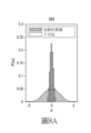
本發明現將參考以下圖示及較佳實施方式之描述進一步闡明,而本發明不限於此。在圖式中:[圖1]展示如根據本發明之一實施方式之經組態以從其船舶甲板上提起物體的浮動船舶之示意性立體圖;[圖2A至圖2B]展示如根據本發明之一實施方式之經組態以在不同狀態下提起物體且將物體置放在支撐結構上的自升式平台之示意性側視圖及後視圖;[圖3]展示如根據先前技術之從吊重構件之吊桿懸置的物體之自由度的示意性表示;[圖4A及圖4B]展示如根據本發明之兩個實施方式之從吊重構件之吊桿懸置的物體之自由度的示意性表示;[圖5]展示如根據本發明之一實施方式之從附接構件懸置的風力渦輪機短艙之示意性立體圖;[圖6]展示如根據本發明之一實施方式之用於從附接構件懸置的風力渦輪機之單樁基座的示意性立體圖;[圖7]展示經組態以應用於本發明之方法中的陀螺儀之實施方式的示意性立體圖;[圖8];[圖8A、圖8B及圖8C]展示如根據先前技術及如根據本發明之實施方式懸置的物體在x、y及z方向上之位置的機率分佈;及最後 [圖9]展示根據本發明之一實施方式之方法的示意性俯視圖。 The present invention will now be further explained with reference to the following illustrations and descriptions of preferred embodiments, but the present invention is not limited thereto. In the drawings: [FIG. 1] shows a schematic three-dimensional view of a floating vessel configured to lift an object from its deck according to one embodiment of the present invention; [FIG. 2A to 2B] show schematic side and rear views of a self-elevating platform configured to lift an object in different states and place the object on a supporting structure according to one embodiment of the present invention; [FIG. 3] shows a schematic representation of the degrees of freedom of an object suspended from a sling of a lifting member according to the prior art; [FIG. 4A and 4B] show schematic representations of the degrees of freedom of an object suspended from a sling of a lifting member according to two embodiments of the present invention; [FIG. 5] shows A schematic three-dimensional diagram of a wind turbine nacelle suspended from an attachment member according to an embodiment of the present invention; [FIG. 6] shows a schematic three-dimensional diagram of a single-pile foundation for a wind turbine suspended from an attachment member according to an embodiment of the present invention; [FIG. 7] shows a schematic three-dimensional diagram of an embodiment of a gyroscope configured for use in the method of the present invention; [FIG. 8]; [FIG. 8A, FIG. 8B and FIG. 8C] show the probability distribution of the position of an object suspended according to the prior art and according to an embodiment of the present invention in the x, y and z directions; and finally [FIG. 9] shows a schematic top view of the method according to an embodiment of the present invention.
參考圖1,展示船舶1,其經專門組態以將呈單樁4形式之風力渦輪機的基座配置在水底5中。視需要,船舶1可裝配有動態定位系統(DP系統)以穩定其位置。船舶1之工作甲板10支撐呈起重機7形式之吊重構件,該吊重構件具備基體72,該基體可圍繞豎直軸樞轉且在其上安裝可圍繞水平軸樞轉之吊桿73。起重機7具備吊重纜索70,呈帶鉤吊重滑車71形式之附接構件附接至該吊重纜索。單樁4可在提起點40處附接至吊重滑車71,且接著藉由起重機7提起,並相對於工作甲板10位移。從吊重纜索70懸置之單樁4可例如藉由旋轉基體72來位移,其中吊桿73將在工作甲板10上方搖擺,及/或藉由向上旋轉吊桿73(仰升)或向下旋轉(俯降)來位移,其中單樁4分別被提起及下降。為了最後將單樁4下降至水底5中,可使用配置在船舶1之側面上的導引籠3。待操控之其他組件可儲存在船舶1之工作甲板10上,諸如風力渦輪機之多個過渡件6及其他單樁4。
With reference to Figure 1, a
將顯而易見的是,風力負荷會阻礙到單樁4之提起及置放,其中船舶1亦經受由波浪作用引起之運動。藉由起重機7提起之自由懸置的單樁4可接觸到相對於工作甲板10、導引籠3及水底5之較大且出人意料的搖擺運動。這使得操作變得更為困難,在強風力負荷之情況下甚至是不可能的。
It will be apparent that wind loads impede the lifting and placing of the
另一應用係關於將諸如短艙8之風力渦輪機組件置放在已經配置在水底5中之呈導管架4'形式的支撐結構上。參考圖2A及圖2B,展示經組態以在海上在導管架4'上組裝風力渦輪機之船舶1'的側視圖。待置放之風力渦輪機的組件可包含展示在圖2A至圖2B中之不同位置中的短艙8、桅桿(部分)8'及/或風力渦輪機之轉子葉片(圖中未示)。船舶1'實質上具備與船舶1相同之裝置,諸如起重機7。出於此原因,類似裝置經編號與圖1中相同。在圖2A至圖2B中,起重滑
車71同樣地展示在不同位置中且待提起之組件為短艙8。船舶1'包含具備支撐工作甲板10之錨樁11'的自升式近海平台。錨樁11'可在豎直方向上運動至海床,且工作甲板10相對於水位之高度位置可藉由藉助於(液壓)千斤頂或齒輪齒條驅動系統相對於錨樁11'位移工作甲板10來改變。為了使得根據本發明之方法能夠執行,船舶1'系泊在存在於海上之導管架4'的附近,且在任何情況下使得導管架4'處於起重機7的範圍內,其中吊桿73處於俯降位置。
Another application is to place wind turbine components such as a
視需要,吊桿73可包含用於起重滑車71之導引裝置74,從而可在至少一個方向上限制起重滑車71之運動。然而,這對於本發明不是必需的。
Optionally, the
在上文所陳述之說明性應用兩者中,根據本發明在位移期間藉由陀螺儀2抑制在波力及風力之影響下發生之起重滑車71及連接至其上之短艙8的搖擺運動,該陀螺儀連接至起重滑車71或短艙8本身且包含圍繞主要旋轉軸旋轉之旋轉對稱的本體。
In both of the illustrative applications described above, according to the invention, the swaying movements of the
吊重纜索70與例如短艙8之間的可能連接展示在圖5中。短艙8包含外殼80及可旋轉輪轂81,該可旋轉輪轂連接至外殼80且具有用於風力渦輪機葉片之安裝點82。短艙8藉由線(90a、90b)從附接構件9懸置,此附接構件在所展示實施方式中包含第一撐桿9a及垂直於其配置之第二撐板部件9b,此等部件在一起形成十字形結構。短艙8藉由分別在外殼80與第二撐桿9b之間及在輪轂81與第一撐桿9a之間延伸的線(90b、90a)懸置。根據此實施方式,第一撐桿9a具備陀螺儀2。
A possible connection between the
吊重纜索70與單樁基座4之間的可能連接展示在圖6中。單樁4懸置在吊索93中,其中吊索93連接至撐桿(不可見),撐桿上側設置有工作平台92。撐桿又藉由吊索或纜索90連接至用於陀螺儀2之外殼94。外殼94又藉由吊索或纜索91從吊重滑車71(亦被稱作起重滑車71)之鉤懸置。根據此實施方式,外殼94包含陀螺儀2。
A possible connection between the
收納在外殼94或第一撐桿9a中之陀螺儀2的可能實施方式展示在圖7中。陀螺儀2包含圍繞主要軸桿21旋轉且呈旋轉對稱之飛輪20的形式的本體。主要軸桿21可旋轉地懸置在第一環形懸置件21'中。第一環形懸置件21'收納在第二環形懸置件22'中,視情況可旋轉地圍繞次要軸桿22。此第二環形懸置件22'視情況可旋轉地藉由第三軸桿23懸置在第三懸置件23'中。在所展示實施方式中,第三懸置件23'包含具備中央開口23a之塊體,陀螺儀2收納在開口23a中。塊形懸置件23'配置在第一撐桿9a、外殼94或另一接收器中,且剛性地錨定至其上。此處重要的是,陀螺儀2經錨定以使得主要旋轉軸桿21實質上豎直延伸,換言之平行於自由懸置(豎直導向)之吊重纜索70的方向75延伸(或替代地,飛輪20之平面實質上垂直於自由懸置之吊重纜索70的方向延伸)。
A possible embodiment of a
第一環形懸置件21'及第二環形懸置件22'與第三懸置件23'之間的耦接可自由旋轉,但亦可各自置放在固定位置中。在所展示實施方式中,第一環形懸置件21'與第二環形懸置件22'之間的耦接經固定以使得兩個環(21'、22')相對於彼此正交地延伸。在被稱為被動之此狀態下,陀螺儀之主要軸桿21將在搖擺運動之情況下將保持實質上平行於搖擺吊重纜索70之當前方向76延伸。第一環形懸置件21'與第二環形懸置件22'之間的耦接亦可經固定以使得兩個環(21'、22')以不同於相對於彼此之正交角度的角度延伸。在被稱為被動之此狀態下,陀螺儀2之主要軸桿21將在搖擺運動之情況下將實質上以相對於搖擺吊重纜索70之當前方向76的該角度延伸。又一選項在於釋放第一環形懸置件21'與第二環形懸置件22'之間的耦接以使得兩個環(21'、22')可相對於彼此自由地旋轉。在上文所陳述之實施方式中,第二環形懸置件22'與第三懸置件23'之間的耦接可經固定或釋放。陀螺儀之可釋放耦接係易於獲得的。
The coupling between the first 21' and second 22' and third 23' ring suspensions can rotate freely, but can also be placed in a fixed position individually. In the embodiment shown, the coupling between the first 21' and second 22' ring suspensions is fixed so that the two rings (21', 22') extend orthogonally relative to each other. In this state, called passive, the
參考圖3,展示藉由吊重纜索70從吊桿73懸置之物體(4,8)。同樣地展示連接至船舶甲板10之笛卡爾(x,y,z)座標系統。(x,y,z)座標系統之原點位
於吊桿73之基體72的位置處,或至少位於吊桿73可圍繞基體72旋轉所圍繞之點處x軸在船之縱向方向上延伸,y軸在船之橫向方向上,且z軸在垂直於船舶甲板10延伸之方向上。如所展示,在波力及風力之影響下懸置之物體(4,8)將如鐘擺一樣運動且經受具有實質上三個自由度之搖擺運動:吊重纜索70與z軸之間的角度θ、方位角ψ,及物體(4,8)圍繞平行於吊重纜索70之當前方向76的軸之旋轉角度φ。
Referring to FIG. 3 , an object ( 4 , 8 ) is shown suspended from a
圖4A及圖4B展示發明性方法之實施方式,其中陀螺儀2併入在吊重纜索70中,例如在用於物體(4,8)之連接構件9中。在圖4A中展示一種方法,其中陀螺儀2在上文所描述之被動狀態下操作,其中陀螺儀2之主要軸桿21將在搖擺運動之情況下保持實質上平行於搖擺吊重纜索70之當前方向76延伸。換言之,如所展示,飛輪20之旋轉向量


表1展示闡明了陀螺儀之一實施方式對懸置之物體的搖擺運動之阻尼效應的比較表,陀螺儀2在諸如風力渦輪機之單樁4、短艙8或桅桿部分8'之物體的提起及位移中的效應藉由包括在表1中。此展示前三列中在x、y及z方向上之物體(4,8)的均方根(「rms」)位移,及後三列中在此等方向上發生之最大位移。第一行(「不受控鐘擺」)展示根據先前技術方法之位移。第二行及第三行(「被動陀螺儀150rpm」、「主動陀螺儀150rpm」)展示當應用發明性方法時之位移,其中陀螺儀2以每分鐘150轉(「rpm」)之轉速分別在被動狀態及主動狀態下操作。第四行及第五行(「被動陀螺儀180rpm」、「主動陀螺儀180rpm」)展示當應用發明性方法時之位移,其中陀螺儀2以每分鐘180轉(「rpm」)之轉速分別在被動狀態及主動狀態下操作。第六行及第七行(「被動陀螺儀200rpm」、「主動陀螺儀200rpm」)展示當應用發明性方法時之位移,其中陀螺儀2以每分鐘200轉(「rpm」)之轉速分別在被動狀態及主動狀態下操作。將顯而易見的是,所有位移相對於已知方法(第一行)顯著地減少(主要在x方向及y方向上)。
Table 1 shows a comparative table illustrating the damping effect of one embodiment of a gyroscope on the pendulum motion of a suspended object, the effect of the
此效應在圖8A、圖8B及圖8C中亦可見,其中物體(4,8)在x、y及z方向上之位置的機率P(x,y,z)經展示為位移之函式。已發現根據本發明之方法顯著地減少搖擺運動之幅度,主要在x方向及y方向上。因此有效地抑制搖擺運動。 This effect is also visible in Figures 8A, 8B and 8C, where the probability P(x,y,z) of the position of the object (4,8) in the x, y and z directions is shown as a function of the displacement. It has been found that the method according to the present invention significantly reduces the amplitude of the swaying motion, mainly in the x and y directions. The swaying motion is thus effectively suppressed.
最後,圖9說明較佳方法,其中浮動船舶1之x軸(船之縱向方向)實質上平行於平均波向100,例如藉由適用於此目的之錨定。使用拖繩101實質上平行於y軸(船之橫向方向)抑制呈撐桿92形式之扣緊構件及呈單樁4形式之連接至其上的物體的搖擺運動。出於此目的,拖繩101連接至錨定至工作甲板10之絞車102,其中絞車102能夠放出或收進拖繩。如上文所描述,藉由收納在外殼94中之陀螺儀2來抑制在x方向上之搖擺運動。
Finally, FIG. 9 illustrates a preferred method in which the x-axis (longitudinal direction of the vessel) of the floating
本發明不限於展示在諸圖中之實施方式,且其許多變化在隨附申 請專利範圍之保護範疇內是可能的。 The present invention is not limited to the embodiments shown in the figures, and many variations are possible within the scope of protection of the accompanying patent applications.
2:陀螺儀 2: Gyroscope
4:單樁 4: Single pile
70:吊重纜索 70: Heavy-duty cable
71:吊重滑車/起重滑車 71: Hoisting pulley/Lifting pulley
90:吊索或纜索 90: sling or cable
91:吊索或纜索 91: sling or cable
92:工作平台/撐桿 92: Working platform/support bar
93:吊索 93: Sling
94:外殼 94: Shell
Claims (14)
Applications Claiming Priority (2)
| Application Number | Priority Date | Filing Date | Title |
|---|---|---|---|
| BE2019/5565 | 2019-08-29 | ||
| BE20195565A BE1027530B1 (en) | 2019-08-29 | 2019-08-29 | Method of lifting an object from a vessel deck |
Publications (2)
| Publication Number | Publication Date |
|---|---|
| TW202124250A TW202124250A (en) | 2021-07-01 |
| TWI879792B true TWI879792B (en) | 2025-04-11 |
Family
ID=67997307
Family Applications (1)
| Application Number | Title | Priority Date | Filing Date |
|---|---|---|---|
| TW109129363A TWI879792B (en) | 2019-08-29 | 2020-08-27 | Method for lifting an object from a vessel deck |
Country Status (8)
| Country | Link |
|---|---|
| US (1) | US12528671B2 (en) |
| EP (1) | EP4021838B1 (en) |
| JP (1) | JP7566885B2 (en) |
| BE (1) | BE1027530B1 (en) |
| DK (1) | DK4021838T3 (en) |
| PL (1) | PL4021838T3 (en) |
| TW (1) | TWI879792B (en) |
| WO (1) | WO2021038057A1 (en) |
Families Citing this family (8)
| Publication number | Priority date | Publication date | Assignee | Title |
|---|---|---|---|---|
| WO2022008020A1 (en) * | 2020-07-09 | 2022-01-13 | Vestas Wind Systems A/S | Mass damper module for wind turbine installation |
| NL2028741B1 (en) * | 2021-07-15 | 2023-01-23 | Itrec Bv | upend crane and installation vessel |
| EP4330176A1 (en) * | 2021-04-30 | 2024-03-06 | Itrec B.V. | Upend crane and installation vessel |
| US12577942B2 (en) | 2021-09-16 | 2026-03-17 | Crowley New Energy, Inc. | Methods of securing a vessel during transportation, off-loading, and installation of wind turbine components |
| EP4253302A1 (en) | 2022-03-29 | 2023-10-04 | Siemens Gamesa Renewable Energy A/S | Method for lifting a wind turbine rotor blade and lifting yoke |
| IT202200006833A1 (en) * | 2022-04-06 | 2023-10-06 | Saipem Spa | System and method of transferring pipeline pipes, in particular from a pipe carrier to a pipeline vessel or an offshore facility |
| CN116306307B (en) * | 2023-03-31 | 2025-09-05 | 中国船舶科学研究中心 | Total longitudinal stress field reconstruction method and device suitable for ships under actual sea conditions |
| CN120348839B (en) * | 2025-06-24 | 2025-09-19 | 江苏扬阳化工设备制造有限公司 | A large glass-lined equipment firing crane |
Citations (4)
| Publication number | Priority date | Publication date | Assignee | Title |
|---|---|---|---|---|
| CN102786001A (en) * | 2011-05-19 | 2012-11-21 | 利勃海尔南兴有限公司 | Crane control |
| CN104039678A (en) * | 2011-11-09 | 2014-09-10 | Ihc荷兰Ie有限公司 | Vessel and crane with full dynamic compensation for vessel and wave motions and a control method thereof |
| WO2018192675A1 (en) * | 2017-04-18 | 2018-10-25 | Siemens Wind Power A/S | Method for installing components of a wind turbine |
| CN109534188A (en) * | 2018-11-16 | 2019-03-29 | 山东大学 | A kind of hard and soft hybrid Wave motion compensation device of sea floating hoisting platform |
Family Cites Families (32)
| Publication number | Priority date | Publication date | Assignee | Title |
|---|---|---|---|---|
| DE2035367A1 (en) | 1970-07-16 | 1972-01-20 | Tax H | Gyro system for the orientation of hanging loads |
| JPS5644419A (en) | 1979-09-20 | 1981-04-23 | Honda Motor Co Ltd | Device for improving combustion of mixture in four-cycle internal combustion engine |
| JPS6356179U (en) * | 1986-09-29 | 1988-04-14 | ||
| JPH0665595B2 (en) | 1988-12-23 | 1994-08-24 | 株式会社大林組 | Attitude control device for suspended loads |
| JPH0680383A (en) | 1992-07-01 | 1994-03-22 | Mitsubishi Heavy Ind Ltd | Slewing control device of suspending/holding device |
| GB9223399D0 (en) | 1992-11-07 | 1992-12-23 | Fidd Peter M | Using the principle of a gyroscope to stabilise/orientate an object |
| JPH06341485A (en) * | 1993-05-31 | 1994-12-13 | Mitsubishi Heavy Ind Ltd | Rotational swinging damping device of suspended object |
| JP3342162B2 (en) * | 1994-03-31 | 2002-11-05 | 三菱重工業株式会社 | Hanging posture control device using gyroscope and control method thereof |
| US5871249A (en) | 1996-11-12 | 1999-02-16 | Williams; John H. | Stable positioning system for suspended loads |
| US7426423B2 (en) * | 2003-05-30 | 2008-09-16 | Liebherr-Werk Nenzing—GmbH | Crane or excavator for handling a cable-suspended load provided with optimised motion guidance |
| US6973847B2 (en) | 2003-06-04 | 2005-12-13 | Gearloose Engineering, Inc. | Gyroscopic roll stabilizer for boats |
| JP2004001750A (en) * | 2003-06-25 | 2004-01-08 | Penta Ocean Constr Co Ltd | Construction of special work boats and offshore structures |
| GB2451093B (en) * | 2007-07-17 | 2009-12-02 | Royal Shakespeare Company | Oscillation damper |
| DE102008024513B4 (en) | 2008-05-21 | 2017-08-24 | Liebherr-Werk Nenzing Gmbh | Crane control with active coast sequence |
| JP5827959B2 (en) | 2010-02-17 | 2015-12-02 | ヴィーム リミテッドVeem Ltd | Fault tolerant ship stabilizer control system |
| JP5644419B2 (en) | 2010-11-24 | 2014-12-24 | 株式会社大林組 | Suspension swivel device and method |
| CN107416699B (en) | 2012-08-06 | 2018-12-14 | 伊特里克公司 | Method for lowering goods from a crane ship into the sea |
| EP2956400B1 (en) * | 2013-02-18 | 2018-02-14 | High Wind N.V. | Device and method for placing a rotor blade of a wind turbine |
| US9731798B2 (en) * | 2013-03-25 | 2017-08-15 | Nauti-Craft Pty Ltd | Stabilising of marine bodies |
| US8938325B1 (en) * | 2013-09-24 | 2015-01-20 | The United States Of America As Represented By The Secretary Of The Navy | Control system for stabilizing a single line suspended mass in yaw |
| ITMI20131958A1 (en) | 2013-11-25 | 2015-05-26 | Milano Politecnico | DEVICE AND PROCEDURE FOR CHECKING THE PENDULUM OF A LOAD SUSPENDED BY A LIFTING EQUIPMENT |
| NO20131594A1 (en) | 2013-12-02 | 2015-06-03 | Savant Tech As | Controllable lift frame |
| KR101607995B1 (en) * | 2014-02-28 | 2016-03-31 | 삼성중공업 주식회사 | Lifting device |
| KR101649942B1 (en) * | 2014-07-09 | 2016-08-30 | 주식회사 포스코건설 | System to control attitude of lifting loads using gyroscope effect and operation method thereof |
| JP6605840B2 (en) * | 2015-05-13 | 2019-11-13 | 鹿島建設株式会社 | Suspended load attitude control device |
| EP3359480B1 (en) | 2015-10-08 | 2023-07-12 | Verton IP Pty Ltd | Materials management systems and methods |
| JP6378250B2 (en) * | 2016-05-20 | 2018-08-22 | 三菱重工業株式会社 | Suspended load elevating apparatus and method for elevating suspended load for wind power generator |
| EP3507490B1 (en) * | 2016-09-02 | 2020-07-29 | National Oilwell Varco Norway AS | Method of building an offshore windmill |
| NL2017937B1 (en) | 2016-12-06 | 2018-06-19 | Itrec Bv | A wave-induced motion compensating crane for use on an offshore vessel, vessel and load transferring method |
| CN110035972B (en) | 2016-12-22 | 2020-09-25 | 菱重维斯塔斯海上风力有限公司 | Components for Rotating Suspended Loads |
| US11066279B2 (en) | 2017-04-24 | 2021-07-20 | Itrec B.V. | Motion compensating crane for use on an offshore vessel |
| NL2020389B1 (en) | 2018-02-06 | 2019-08-14 | Itrec Bv | A crane |
-
2019
- 2019-08-29 BE BE20195565A patent/BE1027530B1/en active IP Right Grant
-
2020
- 2020-08-27 TW TW109129363A patent/TWI879792B/en active
- 2020-08-28 DK DK20760888.6T patent/DK4021838T3/en active
- 2020-08-28 PL PL20760888.6T patent/PL4021838T3/en unknown
- 2020-08-28 JP JP2022513325A patent/JP7566885B2/en active Active
- 2020-08-28 US US17/638,263 patent/US12528671B2/en active Active
- 2020-08-28 EP EP20760888.6A patent/EP4021838B1/en active Active
- 2020-08-28 WO PCT/EP2020/074108 patent/WO2021038057A1/en not_active Ceased
Patent Citations (4)
| Publication number | Priority date | Publication date | Assignee | Title |
|---|---|---|---|---|
| CN102786001A (en) * | 2011-05-19 | 2012-11-21 | 利勃海尔南兴有限公司 | Crane control |
| CN104039678A (en) * | 2011-11-09 | 2014-09-10 | Ihc荷兰Ie有限公司 | Vessel and crane with full dynamic compensation for vessel and wave motions and a control method thereof |
| WO2018192675A1 (en) * | 2017-04-18 | 2018-10-25 | Siemens Wind Power A/S | Method for installing components of a wind turbine |
| CN109534188A (en) * | 2018-11-16 | 2019-03-29 | 山东大学 | A kind of hard and soft hybrid Wave motion compensation device of sea floating hoisting platform |
Also Published As
| Publication number | Publication date |
|---|---|
| US12528671B2 (en) | 2026-01-20 |
| BE1027530B1 (en) | 2021-03-29 |
| EP4021838A1 (en) | 2022-07-06 |
| TW202124250A (en) | 2021-07-01 |
| JP7566885B2 (en) | 2024-10-15 |
| DK4021838T3 (en) | 2025-06-23 |
| US20220289526A1 (en) | 2022-09-15 |
| EP4021838B1 (en) | 2025-05-21 |
| BE1027530A1 (en) | 2021-03-23 |
| WO2021038057A1 (en) | 2021-03-04 |
| PL4021838T3 (en) | 2025-09-01 |
| JP2022545825A (en) | 2022-10-31 |
Similar Documents
| Publication | Publication Date | Title |
|---|---|---|
| TWI879792B (en) | Method for lifting an object from a vessel deck | |
| JP7296973B2 (en) | Apparatus and method for presenting a large elongated object having a longitudinal direction into an underwater bottom | |
| EP2275340B1 (en) | Offshore wind turbine installation | |
| EP3992140B1 (en) | Crane, vessel comprising such a crane, and a method for up-ending a longitudinal structure | |
| NL2021157B1 (en) | Wind turbine installation method | |
| CN106044585B (en) | A kind of offshore wind turbine integral hoisting device for rapid of multiple degrees of freedom compensation | |
| US12152358B2 (en) | Jack-up platform comprising a mooring system and a method for mooring a floating vessel | |
| TW202014602A (en) | Device and method for turning over tubular element with longitudinal direction at outer end | |
| CN113825878A (en) | Vessel and method for installing a pile suitable for supporting an offshore wind turbine | |
| US20120027523A1 (en) | Device and method for assembling a structure at sea | |
| CN202594666U (en) | wind turbine generator installation vessel | |
| US12281635B2 (en) | Device and method for mounting a wind turbine component on a wind turbine tower | |
| JP5306863B2 (en) | Transport method and work boat | |
| JP2023552909A (en) | How to assemble a floating offshore wind farm | |
| CN114072350A (en) | Compact cantilever crane | |
| JP2023529793A (en) | Lifting system and method for lifting elongated objects | |
| EP3943380B1 (en) | Floatable structure comprising a mooring system for mooring a second floating structure, and method for mooring the second floating structure | |
| KR102958626B1 (en) | Device for mounting wind turbine components on a wind turbine tower and method using the same | |
| JP2017166169A (en) | Construction method and work table ship | |
| EP3889029B1 (en) | Device for lifting and placing on a ground surface of an elongate object, and corresponding method | |
| KR20260007377A (en) | Wind turbine installation tower and Wind turbine installation vessel including it | |
| KR20240078194A (en) | Method and System for Transporting and Installing offshore wind power generators in a single lift | |
| JP2024042852A (en) | Method of mounting a wind turbine on a floating body and system for mounting a wind turbine on a floating body |