TWI854027B - Substrate processing method and substrate processing device - Google Patents
Substrate processing method and substrate processing device Download PDFInfo
- Publication number
- TWI854027B TWI854027B TW109131610A TW109131610A TWI854027B TW I854027 B TWI854027 B TW I854027B TW 109131610 A TW109131610 A TW 109131610A TW 109131610 A TW109131610 A TW 109131610A TW I854027 B TWI854027 B TW I854027B
- Authority
- TW
- Taiwan
- Prior art keywords
- substrate
- aforementioned
- temperature
- liquid
- wafer
- Prior art date
Links
Images


Classifications
-
- H—ELECTRICITY
- H10—SEMICONDUCTOR DEVICES; ELECTRIC SOLID-STATE DEVICES NOT OTHERWISE PROVIDED FOR
- H10P—GENERIC PROCESSES OR APPARATUS FOR THE MANUFACTURE OR TREATMENT OF DEVICES COVERED BY CLASS H10
- H10P72/00—Handling or holding of wafers, substrates or devices during manufacture or treatment thereof
- H10P72/04—Apparatus for manufacture or treatment
- H10P72/0402—Apparatus for fluid treatment
- H10P72/0406—Apparatus for fluid treatment for cleaning followed by drying, rinsing, stripping, blasting or the like
- H10P72/0411—Apparatus for fluid treatment for cleaning followed by drying, rinsing, stripping, blasting or the like for wet cleaning or washing
- H10P72/0414—Apparatus for fluid treatment for cleaning followed by drying, rinsing, stripping, blasting or the like for wet cleaning or washing using mainly spraying means, e.g. nozzles
-
- B—PERFORMING OPERATIONS; TRANSPORTING
- B08—CLEANING
- B08B—CLEANING IN GENERAL; PREVENTION OF FOULING IN GENERAL
- B08B3/00—Cleaning by methods involving the use or presence of liquid or steam
- B08B3/02—Cleaning by the force of jets or sprays
-
- B—PERFORMING OPERATIONS; TRANSPORTING
- B08—CLEANING
- B08B—CLEANING IN GENERAL; PREVENTION OF FOULING IN GENERAL
- B08B3/00—Cleaning by methods involving the use or presence of liquid or steam
- B08B3/04—Cleaning involving contact with liquid
-
- B—PERFORMING OPERATIONS; TRANSPORTING
- B08—CLEANING
- B08B—CLEANING IN GENERAL; PREVENTION OF FOULING IN GENERAL
- B08B7/00—Cleaning by methods not provided for in a single other subclass or a single group in this subclass
- B08B7/0014—Cleaning by methods not provided for in a single other subclass or a single group in this subclass by incorporation in a layer which is removed with the contaminants
-
- H—ELECTRICITY
- H10—SEMICONDUCTOR DEVICES; ELECTRIC SOLID-STATE DEVICES NOT OTHERWISE PROVIDED FOR
- H10P—GENERIC PROCESSES OR APPARATUS FOR THE MANUFACTURE OR TREATMENT OF DEVICES COVERED BY CLASS H10
- H10P50/00—Etching of wafers, substrates or parts of devices
- H10P50/60—Wet etching
- H10P50/66—Wet etching of conductive or resistive materials
- H10P50/663—Wet etching of conductive or resistive materials by chemical means only
- H10P50/667—Wet etching of conductive or resistive materials by chemical means only by liquid etching only
-
- H—ELECTRICITY
- H10—SEMICONDUCTOR DEVICES; ELECTRIC SOLID-STATE DEVICES NOT OTHERWISE PROVIDED FOR
- H10P—GENERIC PROCESSES OR APPARATUS FOR THE MANUFACTURE OR TREATMENT OF DEVICES COVERED BY CLASS H10
- H10P70/00—Cleaning of wafers, substrates or parts of devices
- H10P70/20—Cleaning during device manufacture
-
- H—ELECTRICITY
- H10—SEMICONDUCTOR DEVICES; ELECTRIC SOLID-STATE DEVICES NOT OTHERWISE PROVIDED FOR
- H10P—GENERIC PROCESSES OR APPARATUS FOR THE MANUFACTURE OR TREATMENT OF DEVICES COVERED BY CLASS H10
- H10P72/00—Handling or holding of wafers, substrates or devices during manufacture or treatment thereof
- H10P72/04—Apparatus for manufacture or treatment
- H10P72/0402—Apparatus for fluid treatment
- H10P72/0406—Apparatus for fluid treatment for cleaning followed by drying, rinsing, stripping, blasting or the like
-
- H—ELECTRICITY
- H10—SEMICONDUCTOR DEVICES; ELECTRIC SOLID-STATE DEVICES NOT OTHERWISE PROVIDED FOR
- H10P—GENERIC PROCESSES OR APPARATUS FOR THE MANUFACTURE OR TREATMENT OF DEVICES COVERED BY CLASS H10
- H10P72/00—Handling or holding of wafers, substrates or devices during manufacture or treatment thereof
- H10P72/04—Apparatus for manufacture or treatment
- H10P72/0402—Apparatus for fluid treatment
- H10P72/0418—Apparatus for fluid treatment for etching
- H10P72/0422—Apparatus for fluid treatment for etching for wet etching
- H10P72/0424—Apparatus for fluid treatment for etching for wet etching using mainly spraying means, e.g. nozzles
-
- H—ELECTRICITY
- H10—SEMICONDUCTOR DEVICES; ELECTRIC SOLID-STATE DEVICES NOT OTHERWISE PROVIDED FOR
- H10P—GENERIC PROCESSES OR APPARATUS FOR THE MANUFACTURE OR TREATMENT OF DEVICES COVERED BY CLASS H10
- H10P72/00—Handling or holding of wafers, substrates or devices during manufacture or treatment thereof
- H10P72/04—Apparatus for manufacture or treatment
- H10P72/0431—Apparatus for thermal treatment
-
- H—ELECTRICITY
- H10—SEMICONDUCTOR DEVICES; ELECTRIC SOLID-STATE DEVICES NOT OTHERWISE PROVIDED FOR
- H10P—GENERIC PROCESSES OR APPARATUS FOR THE MANUFACTURE OR TREATMENT OF DEVICES COVERED BY CLASS H10
- H10P72/00—Handling or holding of wafers, substrates or devices during manufacture or treatment thereof
- H10P72/06—Apparatus for monitoring, sorting, marking, testing or measuring
- H10P72/0602—Temperature monitoring
-
- H—ELECTRICITY
- H10—SEMICONDUCTOR DEVICES; ELECTRIC SOLID-STATE DEVICES NOT OTHERWISE PROVIDED FOR
- H10P—GENERIC PROCESSES OR APPARATUS FOR THE MANUFACTURE OR TREATMENT OF DEVICES COVERED BY CLASS H10
- H10P72/00—Handling or holding of wafers, substrates or devices during manufacture or treatment thereof
- H10P72/70—Handling or holding of wafers, substrates or devices during manufacture or treatment thereof for supporting or gripping
- H10P72/76—Handling or holding of wafers, substrates or devices during manufacture or treatment thereof for supporting or gripping using mechanical means, e.g. clamps or pinches
- H10P72/7604—Handling or holding of wafers, substrates or devices during manufacture or treatment thereof for supporting or gripping using mechanical means, e.g. clamps or pinches the wafers being placed on a susceptor, stage or support
- H10P72/7618—Handling or holding of wafers, substrates or devices during manufacture or treatment thereof for supporting or gripping using mechanical means, e.g. clamps or pinches the wafers being placed on a susceptor, stage or support characterised by a movable susceptor, stage or support, others than those only rotating on their own vertical axis, e.g. susceptors on a rotating carrousel
Landscapes
- Cleaning Or Drying Semiconductors (AREA)
- Weting (AREA)
Abstract
[課題]一面抑制處理液之消耗量,一面提高液處理之面內均勻性。 [解決手段]一種基板處理方法,係具備有:基板升溫工程,加熱基板,使前述基板的溫度上升;液膜形成工程,在前述基板升溫工程後,一面加熱前述基板並且以第1旋轉數使其旋轉,一面將預濕液供給至前述基板的第1面,在前述基板的第1面形成前述預濕液之液膜;藥液處理工程,在前述液膜形成工程後,一面加熱前述基板並且以低於前述第1旋轉數之第2旋轉數使其旋轉,一面將藥液供給至前述基板的第1面,以前述藥液來處理前述基板的第1面;及基板降溫工程,在前述藥液處理工程後,使前述基板的溫度下降。[Topic] While suppressing the consumption of processing liquid, the uniformity of liquid processing in the surface is improved. [Solution] A substrate processing method comprises: a substrate heating process, heating the substrate to increase the temperature of the substrate; a liquid film forming process, after the substrate heating process, heating the substrate and rotating it at a first rotation number, supplying a pre-wetting liquid to the first surface of the substrate, and forming a liquid film of the pre-wetting liquid on the first surface of the substrate; a chemical liquid processing process, after the liquid film forming process, heating the substrate and rotating it at a second rotation number lower than the first rotation number, supplying a chemical liquid to the first surface of the substrate, and treating the first surface of the substrate with the chemical liquid; and a substrate cooling process, after the chemical liquid processing process, reducing the temperature of the substrate.
Description
本揭示,係關於基板處理方法及基板處理裝置。The present disclosure relates to a substrate processing method and a substrate processing apparatus.
在半導體裝置之製造工程,係包含有:液處理工程,藉由將處理液供給至半導體晶圓等之基板的方式,進行液處理。作為像這樣的液處理之一種,存在有藉由將經加熱的藥液供給至旋轉之基板的表面之中心而進行的藥液洗淨處理或濕蝕刻處理。供給至基板的中心部之經加熱的藥液,係在直到擴展至基板之周緣部為止的期間,溫度下降。又,基板在周速度高的基板周緣部處容易變冷。因此,將經加熱的液體例如水供給至基板之背面,來謀求基板之溫度的均勻化(例如參閱專利文獻1)。 [先前技術文獻] [專利文獻]The manufacturing process of semiconductor devices includes a liquid treatment process in which a treatment liquid is supplied to a substrate such as a semiconductor wafer to perform liquid treatment. As one type of such liquid treatment, there is a liquid cleaning process or a wet etching process in which a heated liquid is supplied to the center of the surface of a rotating substrate. The heated liquid supplied to the center of the substrate decreases in temperature until it spreads to the peripheral portion of the substrate. In addition, the substrate tends to cool down at the peripheral portion of the substrate where the peripheral speed is high. Therefore, a heated liquid such as water is supplied to the back of the substrate to achieve uniform temperature of the substrate (see, for example, Patent Document 1). [Prior Art Document] [Patent Document]
[專利文獻1] 日本特開2015-057816號公報[Patent Document 1] Japanese Patent Application Publication No. 2015-057816
[本發明所欲解決之課題][Problems to be solved by the present invention]
本揭示,係提供一種「在將藥液供給至旋轉之基板的液處理中,一面抑制處理液之消耗量,一面提高液處理之面內均勻性」的技術。 [用以解決課題之手段]This disclosure provides a technology for "suppressing the consumption of the processing liquid and improving the in-plane uniformity of the liquid processing in the liquid processing of supplying the chemical liquid to the rotating substrate." [Means for solving the problem]
本揭示之一態樣的基板處理方法,係具備有:基板升溫工程,加熱基板,使前述基板的溫度上升;液膜形成工程,在前述基板升溫工程後,一面加熱前述基板並且以第1旋轉數使其旋轉,一面將預濕液供給至前述基板的第1面,在前述基板的第1面形成前述預濕液之液膜;藥液處理工程,在前述液膜形成工程後,一面加熱前述基板並且以低於前述第1旋轉數之第2旋轉數使其旋轉,一面將藥液供給至前述基板的第1面,以前述藥液來處理前述基板的第1面;及基板降溫工程,在前述藥液處理工程後,使前述基板的溫度下降。 [發明之效果]The substrate processing method of one aspect of the present disclosure comprises: a substrate heating process, heating the substrate to increase the temperature of the substrate; a liquid film forming process, after the substrate heating process, heating the substrate and rotating it at a first rotation number, while supplying a pre-wetting liquid to the first surface of the substrate, forming a liquid film of the pre-wetting liquid on the first surface of the substrate; a chemical liquid processing process, after the liquid film forming process, heating the substrate and rotating it at a second rotation number lower than the first rotation number, while supplying a chemical liquid to the first surface of the substrate, and treating the first surface of the substrate with the chemical liquid; and a substrate cooling process, after the chemical liquid processing process, reducing the temperature of the substrate. [Effect of the invention]
根據本揭示,可在將藥液供給至旋轉之基板的液處理中,提高液處理之面內均勻性。According to the present disclosure, in liquid processing in which a chemical solution is supplied to a rotating substrate, the in-plane uniformity of the liquid processing can be improved.
參閱附加圖面,說明基板處理裝置之一實施形態。Referring to the attached drawings, one embodiment of a substrate processing apparatus is illustrated.
圖1,係表示本實施形態之基板處理系統之概略構成的圖。在以下中,係為了明確位置關係而規定相互正交之X軸、Y軸及Z軸,並將Z軸正方向設成為垂直向上方向。Fig. 1 is a diagram showing the schematic structure of the substrate processing system of the present embodiment. In the following, in order to clarify the positional relationship, the X-axis, Y-axis and Z-axis are defined to be orthogonal to each other, and the positive direction of the Z-axis is set to be the vertical upward direction.
如圖1所示般,基板處理系統1,係具備有:搬入搬出站2;及處理站3。搬入搬出站2與處理站3,係鄰接設置。As shown in Fig. 1, the
搬入搬出站2,係具備有:載體載置部11;及搬送部12。在載體載置部11,係載置有以水平狀態收容複數片基板,本實施形態為半導體晶圓(以下稱為晶圓W)的複數個載體C。The loading/
搬送部12,係鄰接設置於載體載置部11,在內部具備有基板搬送裝置13與收授部14。基板搬送裝置13,係具備有保持晶圓W的晶圓保持機構。又,基板搬送裝置13,係可朝水平方向及垂直方向移動和以垂直軸為中心旋轉,並使用晶圓保持機構,在載體C與收授部14之間進行晶圓W的搬送。The
處理站3,係鄰接設置於搬送部12。處理站3,係具備有:搬送部15;及複數個處理單元16。複數個處理單元16,係被排列設置於搬送部15的兩側。The
搬送部15,係在內部具備有基板搬送裝置17。基板搬送裝置17,係具備有保持晶圓W的晶圓保持機構。又,基板搬送裝置17,係可朝水平方向及垂直方向移動和以垂直軸為中心旋轉,並使用晶圓保持機構,在收授部14與處理單元16之間進行晶圓W的搬送。The
處理單元16,係對藉由基板搬送裝置17所搬送的晶圓W進行預定之基板處理。The
又,基板處理系統1,係具備有控制裝置4。控制裝置4,係例如電腦,具備有控制部18與記憶部19。在記憶部19,係儲存有程式,該程式,係控制基板處理系統1中所執行的各種處理。控制部18,係藉由讀出並執行被記憶於記憶部19之程式的方式,控制基板處理系統1的動作。The
另外,該程式,係亦可為被記錄於電腦可讀取之記憶媒體者,且亦可為從該記憶媒體被安裝於控制裝置4的記憶部19者。作為電腦可讀取之記憶媒體,係例如有硬碟(HD)、軟碟片(FD)、光碟(CD)、磁光碟(MO)、記憶卡等。In addition, the program may be recorded in a computer-readable storage medium, and may be installed from the storage medium to the
在如上述般所構成之基板處理系統1中,係首先,搬入搬出站2之基板搬送裝置13從被載置於載體載置部11的載體C取出晶圓W,並將取出之晶圓W載置於收授部14。載置於收授部14之晶圓W,係藉由處理站3的基板搬送裝置17,從收授部14被取出且搬入至處理單元16。In the
搬入至處理單元16之晶圓W,係在藉由處理單元16予以處理後,藉由基板搬送裝置17,從處理單元16被搬出且載置於收授部14。而且,載置於收授部14之處理完畢的晶圓W,係藉由基板搬送裝置13而返回到載體載置部11的載體C。After the wafer W is processed in the
其次,參閱圖2,說明關於處理單元16的構成。Next, referring to FIG. 2 , the structure of the
處理單元16,係具備有:腔室20;基板保持旋轉機構30;第1處理流體供給部40;第2處理流體供給部50;及回收罩杯60。The
腔室20,係收容有基板保持旋轉機構30及回收罩杯60。在腔室20之頂部,係設置有FFU(Fan Filter Unit)21。FFU21,係在腔室20內形成下降流。The
基板保持旋轉機構30,係具備有:基板保持部31;支柱部32;及旋轉驅動部33。基板保持部31,係被構成為機械卡盤,該機械卡盤,係具有:圓盤狀之基座31a;及複數個把持爪31b,沿著圓周方向而隔開間隔地被設置於基座31a的外周緣部。基板保持部31,係藉由把持爪31b,水平地保持晶圓W。在把持爪31b抓取基板時,在基座31a的上面與晶圓W的下面之間形成有間隙。The substrate holding and
支柱部32,係延伸於垂直方向的中空構件。支柱部32之上端,係被連結於基座31a。旋轉驅動部33使支柱部32旋轉,藉此,基板保持部31及被其保持之晶圓W繞垂直軸旋轉。The
回收罩杯60,係被配置為包圍基板保持部31。回收罩杯60,係捕集從被保持於基板保持部31而旋轉之晶圓W飛散的處理液。在回收罩杯60之底部,係形成有排液口61。藉由回收罩杯60所捕集到之處理液,係從排液口61排出至處理單元16的外部。在回收罩杯60之底部,係形成有排氣口62。回收罩杯60之內部空間,係經由排氣口62被吸引。從FFU21所供給之氣體,係在被吸入到回收罩杯60的內部後,經由排氣口62排出至處理單元16的外部。The
第1處理流體供給部40,係將各種處理流體(液體、氣體、氣液混合流體等)供給至基板保持部31所保持之晶圓W的上面(一般為形成有元件之晶圓W的表面)。第1處理流體供給部40,係具有:複數個表面噴嘴41,朝向晶圓W之上面(第1面)吐出處理流體。表面噴嘴41之數量,係為了進行由處理單元16所執行的處理而僅設置所需數量。在圖2,雖係描繪了5個表面噴嘴41,但並不限定於該數量。The first processing
第1處理流體供給部40,係具有1個以上(在圖示例中,係2個)噴嘴臂42。各噴嘴臂42,係載持複數個表面噴嘴41中之至少一者。各噴嘴臂42,係可使經載持之表面噴嘴41在晶圓W的旋轉中心之大概正上方的位置(處理位置)與比回收罩杯60之上端開口更外側的退避位置之間移動。The first processing
從對應之處理流體供給機構43對表面噴嘴41的各者供給處理流體。處理流體供給機構43,係可由「儲槽、鋼瓶、工廠設施等的處理流體供給源、將處理流體從處理流體供給源供給至表面噴嘴41的供給管路、設置於供給管路的開關閥及流量控制閥等的流量調節裝置」來構成。為了排出滯留於表面噴嘴41及其附近之供給管路內的處理流體(特別是處理液),可將排放管路連接於供給管路。像這樣的處理流體供給機構43,係在半導體製造裝置之發明所屬的技術領域中廣為周知,從而省略構造的圖示及詳細說明。以在各表面噴嘴41位於退避位置時,可進行虛擬分配的方式,在處理單元16設置液承接部(未圖示)。The processing fluid is supplied to each of the
第2處理流體供給部50,係將各種處理流體(處理液、處理氣體等)供給至基板保持部31所保持之晶圓W的下面(一般為未形成元件之晶圓W的背面)。第2處理流體供給部50,係具有:1個以上(在圖示例中,係2個)之背面噴嘴51A、51B,朝向晶圓W的下面(第2面)吐出處理流體。如圖2概略所示般,在中空之支柱部32的內部,處理液供給管52沿垂直方向延伸。在處理液供給管52內,沿上下方向延伸之2個流路各自的上端開口部發揮背面噴嘴51A、51B的作用。處理液供給管52,係以在基板保持部31及支柱部32旋轉時亦可維持非旋轉狀態的方式,被設置於支柱部32內。The second processing
用以對晶圓W進行調溫之調溫用DIW(純水)從調溫用DIW供給機構53A被供給至背面噴嘴51A(加熱流體噴嘴)。背面噴嘴51A及調溫用DIW供給機構53A,係構成加熱流體(調溫用流體)的供給機構。用以冷卻晶圓W之冷卻用的CDIW(常溫的DIW)從CDIW供給機構53B(僅在圖2中表示)被供給至背面噴嘴51B。背面噴嘴51B及CDIW供給機構53B,係構成冷卻用流體的供給機構。CDIW供給機構53B,係例如亦可為具有與先前簡單說明之表面噴嘴41用的處理流體供給機構43相同之一般習知的構成者。DIW (pure water) for temperature control for controlling the temperature of the wafer W is supplied from the
在本說明書中,係為了與經加熱的DIW即「 HDIW」有所區別而將常溫(例如24℃)的DIW稱為「CDIW」。In this manual, DIW at room temperature (e.g. 24°C) is referred to as "CDIW" to distinguish it from heated DIW, i.e. "HDIW".
其次,參閱圖3,說明關於背面噴嘴51A用之調溫用DIW供給機構53A的構成。調溫用DIW供給機構53A,係被逐一設置於複數個處理單元16(16-1、16-2、16-3,・・・)之各者。各調溫用DIW供給機構53A之構成,係實質上彼此相同。Next, referring to FIG. 3 , the structure of the temperature-adjusting
基板處理系統1,係具有:HDIW幹管23,被連接於HDIW之供給源;及CDIW幹管24,被連接於CDIW之供給源。幹管23、24,係將HDIW及CDIW供給至1台基板處理系統1所具備之複數個處理單元16的全部。在HDIW幹管23,係設置有溫度感測器25,在CDIW幹管24,係設置有溫度感測器26。The
HDIW之供給源及CDIW之供給源,係設置有基板處理系統1之半導體裝置製造工廠的工廠設施最為普遍。然而,例如HDIW之供給源,係亦可為被設置成基板處理系統1的構成要素之儲存HDIW的儲槽。DIW從作為工廠設施的HDIW之供給源及CDIW之供給源被供給至儲槽。在該情況下,被連接於儲槽並且具備有泵及加熱器的循環管路相當於HDIW幹管23。HDIW之供給源,係亦可為「對從作為工廠設施的HDIW之供給源及CDIW之供給源所供給的DIW進行加熱而送出」的熱水產生器(hot water
generator)。The HDIW supply source and the CDIW supply source are most commonly found in a factory facility of a semiconductor device manufacturing factory equipped with a
調溫用DIW供給機構53A,係具有從HDIW幹管23分歧的主管路531(加熱流體管線)。在主管路531,係從上游側依序設置有流量計532、定壓閥533、開關閥534、第1合流點535、第2合流點536、第1分歧點537、開關閥538及第2分歧點539。主管路531之下游端,係經由處理液供給管52內的流路被連接於背面噴嘴51A。The temperature-adjusting
流量計532及定壓閥533,係構成流量調整部,該流量調整部,係調整流動於主管路531之HDIW的流量。定壓閥533,係具有引導口(詳細內容未圖示)。定壓閥533,係以實現因應從未圖示之電空調整器被供給至引導口的操作壓力(空氣壓)之二次側壓力的方式,進行動作。供給至定壓閥533之引導口的操作壓力,係以使流量計532之檢測流量成為所期望的值(設定值)的方式,藉由控制裝置(圖1之控制裝置4或其低階控制器)進行反饋控制。The
調溫用DIW供給機構53A,係更具有從CDIW幹管24分歧的稀釋液管路540。稀釋液管路540,係在分歧點541分歧成第1分歧稀釋液管路542與第2分歧稀釋液管路543。在第1分歧稀釋液管路542,係介設有節流器544與開關閥545。在第2分歧稀釋液管路543,係介設有節流器546與開關閥547。在圖示例中,節流器544、546,係被構成為附有止回閥的孔口(固定節流器)。第1分歧稀釋液管路542及第2分歧稀釋液管路543,係分別在第1合流點535及第2合流點536被連接於主管路531。The temperature-adjusting
在比稀釋液管路540之分歧點541更上游側,係設置有流量計548及定壓閥549。流量計548及定壓閥549,係具有與流量計532及定壓閥533相同的構成及作用。A
在第1分歧點537中,第1排放管線550從主管路531分歧。在第1排放管線550,係從上游側依序設置有開關閥551、溫度感測器552及節流器553(在圖示例中,係附有止回閥的孔口(固定節流器))。At the
在第2分歧點539中,第2排放管線554從主管路531分歧。在第2排放管線554,係從上游側依序設置有開關閥555及節流器556(在圖示例中,係附有止回閥的孔口(固定節流器))。At the second branch point 539, the
在比主管路531之第2分歧點539更下游側,係設置有溫度感測器557。A
在HDIW之供給源及CDIW之供給源為工廠設施的情況下,流動於HDIW幹管23之HDIW的溫度,係例如70℃,流動於CDIW幹管24之CDIW的溫度,係例如24℃。由於該溫度,係受到外部氣溫、無塵室內溫度之變動等的要因而稍微變動,因此,藉由溫度感測器25、26來監視。When the HDIW supply source and the CDIW supply source are factory facilities, the temperature of the HDIW flowing through the
如後述般,以晶圓W之溫度調節為主要目的,調溫用HDIW從背面噴嘴51A被供給至晶圓W的背面。調溫用DIW供給機構53A,係可僅將HDIW或HDIW與CDIW之混合液從背面噴嘴51A供給至晶圓W的背面。從背面噴嘴51A被供給至晶圓W之DIW的溫度,係可藉由使HDIW與CDIW之混合比(流入主管路531之HDIW的流量與經由稀釋液管路540(542、543)流入主管路531之CDIW的流量之比率)變化的方式,進行調節。As described later, the temperature-adjusting HDIW is supplied from the
作為一例,從背面噴嘴51A待供給至晶圓W之背面的DIW之流量為1500ml/min,溫度為65℃。在該情況下,雖應將70℃之HDIW的流量設為1340ml/min且將24℃之CDIW的流量設為160ml/min,但可藉由計算來輕易求出。For example, the flow rate of DIW supplied from the
控制裝置4,係進行上述計算。而且,控制裝置4,係將藉由計算所獲得之HDIW流量作為設定值(目標值)SV而賦予至由流量計532、定壓閥533及未圖示之電空調整器所構成的HDIW流量反饋控制系統。又,相同地,控制裝置4,係將藉由計算所獲得之CDIW流量作為設定值(目標值)SV而賦予至由流量計548、定壓閥549及未圖示之電空調整器所構成的CDIW流量反饋控制系統,並且亦輸出指定待開放之分歧稀釋液管路(542或543)的開關閥(545或547)之信號。The
另外,在上述HDIW流量反饋控制系統及CDIW流量反饋控制系統中,流量計532、548之檢測流量為測定值PV,從電空調整器被賦予至定壓閥533、549的操作壓力為操作量MV。控制裝置4,係因應測定值PV相對於設定值SV的偏差,調節操作量MV。In the above-mentioned HDIW flow feedback control system and CDIW flow feedback control system, the flow detected by the
為了擴大混合比之範圍(最大值/最小值之比),第1分歧稀釋液管路542(第1低溫流體管線)之節流器544的開口面積,係被設定為大於第2分歧稀釋液管路543(第2低溫流體管線)之節流器546的開口面積。因此,藉由選擇性地開啟第1分歧稀釋液管路542的開關閥545及第2分歧稀釋液管路543的開關閥547之任一者的方式,能實現比可由定壓閥549單獨實現之流量範圍(最大流量/最小流量之比)顯著更大的流量範圍且以高精度進行流量調節。In order to expand the range of the mixing ratio (maximum value/minimum value ratio), the opening area of the
分歧稀釋液管路(542、543、・・・)之數量,係並不限定於圖示的2個,亦可為3個以上。在該情況下,各分歧稀釋液管路,係並列地被連接於主管路531,在各分歧稀釋液管路,係設置有開關閥(545、547、・・・)及節流器(544、546、・・・)。從擴大混合比之範圍的觀點來看,節流器之開口面積,係彼此不同為較佳。The number of branch diluent pipelines (542, 543, ...) is not limited to the two shown in the figure, and may be three or more. In this case, each branch diluent pipeline is connected in parallel to the
第1排放管線550,係直至溫度穩定為止的期間,被使用於用以不將DIW供給至晶圓W而廢棄的操作(亦稱為「拋棄」或「虛擬分配」)。The
第2排放管線554,係被使用於廢棄「殘留於背面噴嘴51A、與背面噴嘴51A連通之處理液供給管52內的流路及其附近之管路」的DIW。藉此,可防止「在開始吐出來自背面噴嘴51A之調溫用DIW後立即吐出未被溫度控制之DIW」的情形。The
調溫用DIW供給機構53A,係亦可以從背面噴嘴51A單獨地吐出CDIW(未被混合至HDIW之CDIW)的方式,進行動作。在該情況下,亦可省略背面噴嘴51B及CDIW供給機構53B。但是,如此一來,由於背面噴嘴51及連接於背面噴嘴51之管路的溫度變得不穩定,因此,將「背面噴嘴51B及CDIW供給機構53B」與「背面噴嘴51A及調溫用DIW供給機構53A」分開設置者為較佳。The temperature-adjusting
其次,參閱圖3~圖8,說明關於在處理單元16內對晶圓W所執行的液處理。晶圓W,係以使處理對象面即表面成為上面的方式,藉由基板保持旋轉機構30被保持為水平姿勢,並繞垂直軸線旋轉。晶圓W之旋轉,係持續直至一連串的工程結束為止。Next, referring to FIG. 3 to FIG. 8 , the liquid treatment performed on the wafer W in the
另外,在以下之液處理的說明中並沒有特別說明的情況下,從表面噴嘴41被供給至晶圓W之表面的處理液之著液點,係指晶圓W的旋轉中心或其附近。在從表面噴嘴41被供給至晶圓W之表面的處理液之著液點成為晶圓周緣部的情況下,當使表面噴嘴41進行掃描時,係每次記述該意旨。In addition, unless otherwise specified in the following description of liquid processing, the landing point of the processing liquid supplied from the
[晶圓升溫工程]
首先,實施使晶圓W升溫至適於液處理之溫度的晶圓升溫工程(基板升溫工程)。晶圓升溫工程,係藉由「將與後述的本處理工程(藥液處理工程)中所使用之藥液不同的調溫用之流體(經加熱的流體)供給至晶圓W之背面」的方式來進行。藉由調溫流體供給部(加熱流體供給部)供給調溫用之流體,該調溫流體供給部,係由背面噴嘴51A及調溫用DIW供給機構53A等所構成。[Wafer heating process]
First, a wafer heating process (substrate heating process) is performed to heat the wafer W to a temperature suitable for liquid processing. The wafer heating process is performed by "supplying a temperature-regulating fluid (heated fluid) different from the chemical liquid used in the later-described processing process (chemical liquid processing process) to the back side of the wafer W". The temperature-regulating fluid is supplied by a temperature-regulating fluid supply unit (heating fluid supply unit), which is composed of a
調溫用之流體,係廉價且熱容量大為較佳,最適當的調溫用流體為水。然而,調溫用之流體,係亦可為除了水(DIW)以外的流體例如氣體(具體而言,係例如經加熱的氮氣)。The temperature-control fluid is preferably inexpensive and has a large heat capacity, and the most suitable temperature-control fluid is water. However, the temperature-control fluid may be a fluid other than water (DIW), such as gas (specifically, heated nitrogen).
在晶圓升溫工程之前,於開關閥538關閉的狀態下開啟開關閥555,並經由第2排放管線554廢棄殘留於從分歧點539至背面噴嘴51A之間的DIW。Before the wafer heating process, the on-off
另一方面,於開關閥551開啟的狀態下開啟開關閥534,HDIW以經控制之流量流入主管路531,又,開啟開關閥545或開關閥547,CDIW以經控制之流量經由合流點535或536流入主管路531。此時,如先前所說明般,藉由控制裝置4所計算出之HDIW流量作為初始設定值而賦予至HDIW流量反饋控制系統,且藉由控制裝置4所計算出之CDIW流量作為初始設定值而賦予至CDIW流量反饋控制系統。On the other hand, when the on-off
HDIW與CDIW在主管路531內被混合,生成調溫用DIW。為了促進混合,亦可在第2合流點536與第1分歧點537之間設置管內混合器等的混合促進裝置。HDIW and CDIW are mixed in the
流量、溫度皆在開始生成調溫用DIW後立即傾向於不穩定。溫度之不穩定,係主要起因於HDIW流動之前的管路(特別是主管路531)變冷。因此,於開關閥538關閉的狀態下開啟開關閥551,並經由第1排放管線550廢棄開始生成後的調溫用DIW(虛擬分配)。流動於第1排放管線550之調溫用DIW的溫度,係藉由溫度感測器552來監視。The flow rate and temperature tend to be unstable immediately after the generation of the temperature-regulating DIW begins. The temperature instability is mainly caused by the cooling of the pipeline (especially the main pipeline 531) before the HDIW flows. Therefore, the on-off
當開關閥551開啟而經過預先設定之時間且溫度穩定後,控制裝置4,係亦可基於溫度感測器552的檢測值,以使溫度感測器552之檢測值成為目標溫度的方式,修正HDIW流量的(初始)設定值(SV)及CDIW流量的(初始)設定值(SV)。亦即,在溫度感測器552之檢測值未上升至目標值的情況下,係例如可進行使HDIW流量之設定值(SV)增加並且使CDIW流量之設定值(SV)減少的修正,且持續HDIW流量及CDIW流量的反饋控制。When the
當溫度感測器552之檢測溫度穩定於目標值後,關閉開關閥551並且開啟開關閥538。開關閥555,係亦可當經由了第2排放管線554之殘留DIW的排出結束後立即關閉,或亦可與開關閥551關閉的同時關閉。藉此,預定溫度之調溫用DIW從背面噴嘴51A以預定流量朝向晶圓W之背面的中央部(晶圓的旋轉中心或其附近)吐出。來自背面噴嘴51A之調溫用DIW的吐出流量,係例如可設成為1500ml/min。When the detected temperature of the
在晶圓升溫工程中,在CDIW未被混合至HDIW且從背面噴嘴51A供給的情況下,係首先,於關閉了開關閥545、547、538的狀態下,開啟開關閥551。又,將開關閥555開啟,預先排出滯留於比分歧點539更下游側的液體。如此一來,從HDIW幹管23流入主管路531之HDIW,係流入第1排放管線550。此時,藉由溫度感測器552,監視流動於第1排放管線550之HDIW(調溫用DIW)的溫度。當溫度感測器552之檢測值上升而達到穩定後,將開關閥551、555關閉,並開啟開關閥538。藉此,從背面噴嘴51A開始吐出HDIW。在該時間點,係由於比主管路531之分歧點537更上游側的部分被充分地加溫,因此,從背面噴嘴51A所吐出之HDIW的溫度,係在開始吐出後,於比較短的時間內達到穩定。In the wafer temperature raising process, when CDIW is not mixed with HDIW and is supplied from the
在調溫用DIW從背面噴嘴51A被吐出之前,晶圓W開始旋轉。如圖4A所示般,供給至晶圓W之背面中央部的調溫用DIW,係藉由離心力流向晶圓W之周緣部並往晶圓W的外方脫離。此時,晶圓W之背面被調溫用DIW的液膜覆蓋。晶圓W,係藉由被調溫用DIW加熱的方式而升溫。Before the temperature-adjusting DIW is ejected from the
晶圓升溫工程中之晶圓W的旋轉數,係可設成為如保證被供給至晶圓W之背面中央部的調溫用DIW均勻地覆蓋晶圓W之背面內般的旋轉數,例如200rpm以上之適當的旋轉數。另外,若晶圓W之旋轉數過高,則往晶圓W的外方飛散之調溫用DIW與回收罩杯60激烈地碰撞而大量的DIW霧氣漂浮於晶圓W之周圍,並不佳。又,若晶圓W之旋轉數過高,由於周速度高的晶圓周緣部容易變冷而損害晶圓溫度之面內均勻性,因此,並不佳。考慮上述情形而設定晶圓升溫工程中之晶圓W的旋轉數為較佳。The number of rotations of the wafer W during the wafer heating process can be set to a number of rotations that ensures that the temperature-regulating DIW supplied to the center of the back side of the wafer W evenly covers the back side of the wafer W, for example, an appropriate number of rotations of more than 200 rpm. In addition, if the number of rotations of the wafer W is too high, the temperature-regulating DIW scattered to the outside of the wafer W collides violently with the
另外,在晶圓升溫工程的開始後至晶圓降溫工程的開始之前為止的期間,一直從背面噴嘴51A吐出調溫用DIW。可藉由溫度感測器557,監視從背面噴嘴51A所吐出之調溫用DIW的溫度。可基於溫度感測器557之檢測結果,進行如前述般的HDIW流量之設定值(SV)及CDIW流量之設定值(SV)的修正。如後述般,在使從背面噴嘴51A所吐出之調溫用DIW的溫度從70℃下降至52℃時,亦可使用該修正。In addition, the temperature-adjusting DIW is continuously discharged from the
在晶圓升溫工程中,係如圖4B及圖4C所示般,亦可將調溫用DIW供給至晶圓W的表面。在該情況下,在將調溫用DIW供給至晶圓W的表面之前進行虛擬分配,並將調溫用DIW供給用之表面噴嘴41及連接於調溫用DIW供給用之表面噴嘴41的管路充分地加溫為較佳。In the wafer heating process, as shown in FIG4B and FIG4C , DIW for temperature adjustment may also be supplied to the surface of the wafer W. In this case, it is preferred to perform virtual distribution before supplying DIW for temperature adjustment to the surface of the wafer W, and to sufficiently heat the
在圖4B中,係調溫用DIW從調溫用DIW供給用之表面噴嘴41(以下,為了方便亦稱為「表面調溫噴嘴41A」)以比較大的流量僅被供給至晶圓W之表面的中央部。供給至晶圓表面中央部之調溫用DIW,係藉由離心力流向晶圓W之周緣部並往晶圓W的外方脫離(飛散)。此時,晶圓W之表面的整個區域被調溫用DIW的液膜覆蓋。晶圓W,係亦藉由被供給至表面的調溫用DIW加熱而升溫。藉此,與圖4A的情形相比,可使晶圓W更迅速地升溫。In FIG. 4B , the temperature-control DIW is supplied only to the central portion of the surface of the wafer W from the
在圖4C中,係調溫用DIW從表面調溫噴嘴41A以比較小的流量僅被供給至晶圓W之表面周緣部。此時,例如亦可使表面調溫噴嘴41A往半徑方向往復運動,並使調溫用DIW對晶圓W之表面上的著液點之半徑方向位置重覆變化。此時,在晶圓W之表面中,係只有周緣部之環狀的區域被調溫用DIW的液膜覆蓋。在圖4C的情況下,係由於對傾向於容易變冷之晶圓W的周緣部進行局部地加熱,因此,可更提高晶圓面內之溫度的均勻性。亦可在將表面調溫噴嘴41A固定於相同位置(例如圖4C所示的位置)以代替使表面調溫噴嘴41A往復運動的狀態下,吐出調溫用DIW。In FIG. 4C , the temperature-control DIW is supplied from the surface temperature-
在晶圓升溫工程中,係即便在採用圖4A、圖4B、圖4C之任一程序的情況下,亦將晶圓W升溫至比後述本處理工程中之晶圓溫度(亦稱為「本處理時晶圓溫度」。此為50℃。)高的溫度(例如70℃)。「在暫時升溫至比本處理時晶圓溫度高的第1溫度後使其降溫者可縮短直至晶圓W之溫度穩定於本處理時晶圓溫度為止所需要的時間」,係亦藉由實際的試驗操作得到確認。In the wafer heating process, even when any of the procedures of FIG. 4A, FIG. 4B, and FIG. 4C is adopted, the temperature of the wafer W is raised to a temperature (e.g., 70°C) higher than the wafer temperature in the present process described later (also referred to as "the wafer temperature during the present process", which is 50°C). "By temporarily raising the temperature to a first temperature higher than the wafer temperature during the present process and then cooling it down, the time required until the temperature of the wafer W stabilizes at the wafer temperature during the present process can be shortened," which has also been confirmed through actual test operations.
[液膜形成工程及本處理工程] 其次,進行液膜形成工程與本處理工程(藥液處理工程),該液膜形成工程,係在晶圓W之表面整個區域形成預濕液的液膜,該本處理工程,係以藥液來處理晶圓W的表面。預濕液,係亦可為與後述本處理工程中所使用之藥液相同的藥液,或亦可為容易置換成後述本處理工程中所使用之藥液的其他液體(例如DIW、IPA(異丙醇)等)。[Liquid film formation process and main treatment process] Next, a liquid film formation process and a main treatment process (chemical liquid treatment process) are performed. The liquid film formation process is to form a liquid film of a pre-wetting liquid on the entire surface of the wafer W, and the main treatment process is to treat the surface of the wafer W with a chemical liquid. The pre-wetting liquid may be the same chemical liquid as the chemical liquid used in the main treatment process described later, or may be other liquids that are easily replaced with the chemical liquid used in the main treatment process described later (e.g., DIW, IPA (isopropyl alcohol) etc.).
在圖4A、圖4B或圖4C之晶圓升溫工程結束後,亦繼續從背面噴嘴51A持續吐出調溫用DIW至晶圓W的背面。但是,從背面噴嘴51A所吐出之調溫用DIW的溫度,係藉由調節CDIW之混合比的方式,下降至與本處理時晶圓溫度大致相等的溫度(例如52℃)。藉此,晶圓W之溫度,係朝向本處理時晶圓溫度下降。After the wafer heating process of FIG. 4A , FIG. 4B or FIG. 4C is completed, the temperature-adjusting DIW is continuously ejected from the
在晶圓升溫工程中,如圖4A所示般,在未將調溫用DIW供給至晶圓W之表面的情況下,係從藥液供給用之表面噴嘴41(以下,為了方便亦稱為「表面藥液噴嘴41B」。),供給與本處理工程中所使用的藥液相同之常溫的藥液作為預濕液(參閱圖5A)。常溫的藥液,係使晶圓W以第1旋轉數旋轉的同時,從表面藥液噴嘴41B以第1吐出流量被供給至晶圓W之表面的中央部(晶圓的旋轉中心或其附近)。In the wafer heating process, as shown in FIG. 4A , when DIW for temperature adjustment is not supplied to the surface of the wafer W, a normal temperature chemical liquid, which is the same as the chemical liquid used in this process, is supplied as a pre-wetting liquid from the
此時,為了將藥液迅速地擴展至晶圓W之表面整個區域,上述第1旋轉數,係設成為比較高為較佳(例如800rpm左右)。又,上述第1吐出流量,係亦可設成為比較大(例如1000ml/min左右)。藉由將第1吐出流量設成為比較大的方式,即便晶圓W之旋轉數比較高,亦可確實地以藥液之液膜來覆蓋晶圓W之表面的整個區域。又,藉由將第1吐出流量設成為比較大的方式,可確實地防止「在液膜形成工程開始時,成為比較高溫(例如70℃左右)之被供給至晶圓W的表面之藥液蒸發而產生乾燥區域」的情形。At this time, in order to quickly spread the chemical solution to the entire surface area of the wafer W, the above-mentioned first rotation number is preferably set to a relatively high value (for example, about 800 rpm). In addition, the above-mentioned first discharge flow rate can also be set to a relatively large value (for example, about 1000 ml/min). By setting the first discharge flow rate to a relatively large value, even if the rotation number of the wafer W is relatively high, the entire surface area of the wafer W can be reliably covered with a liquid film of the chemical solution. In addition, by setting the first discharge flow rate to a relatively large value, it is possible to reliably prevent the situation in which "at the beginning of the liquid film formation process, the chemical solution supplied to the surface of the wafer W, which becomes a relatively high temperature (for example, about 70°C), evaporates and produces a dry area."
另外,在難以形成均勻之液膜條件的情況下,係為了防止指狀水侵(fingering),特別是將上述第1旋轉數及上述第1吐出流量設定得較大為較佳。具體而言,係例如考慮使用對晶圓W之浸濕性低的藥液或高黏性之藥液的情形等。In addition, in the case where it is difficult to form a uniform liquid film, in order to prevent fingering, it is particularly preferred to set the first rotation number and the first discharge flow rate to be larger. Specifically, for example, the case where a liquid with low wettability to the wafer W or a liquid with high viscosity is used.
在晶圓升溫工程中,如圖4B或圖4C所示般,在將調溫用DIW從表面調溫噴嘴41A亦供給至晶圓表面的情況下,係停止從表面調溫噴嘴41A吐出調溫用DIW。而且,從表面藥液噴嘴41B,將與本處理工程中所使用的藥液相同之常溫的藥液作為預濕液而供給至晶圓W之表面的中央部,藉此,執行液膜形成工程。該情形亦成為圖5A所示的狀態。In the wafer temperature raising process, as shown in FIG. 4B or FIG. 4C, when the temperature-adjusting DIW is also supplied to the wafer surface from the surface temperature-adjusting
在從圖4B或圖4C之狀態移行至液膜形成工程的情況下,係為了防止被形成於晶圓W之表面的凹凸圖案倒塌,而在調溫用DIW從凹凸圖案內脫離之前,將藥液供給至晶圓W的表面為較佳。When the process of liquid film formation is carried out from the state of FIG. 4B or FIG. 4C , it is preferable to supply the chemical solution to the surface of the wafer W before the temperature-adjusting DIW is separated from the concave-convex pattern in order to prevent the concave-convex pattern formed on the surface of the wafer W from collapsing.
此時,如以下般地切換先前所供給的第1處理液(在此,係調溫用DIW)與其後所供給的第2處理液(在此,係藥液)為較佳。首先,自「第1處理液從第1表面噴嘴41(在此,係表面調溫噴嘴41A)著液於晶圓W的表面之旋轉中心」的狀態開始。從該狀態,使第2處理液著液於稍微遠離晶圓W之表面的旋轉中心的位置,該第2處理液,係從位於接近第1表面噴嘴41之位置的第2表面噴嘴41(在此,係表面藥液噴嘴41B)所吐出。其後,以使第1處理液的著液點遠離晶圓之旋轉中心且使第2處理液的著液點接近晶圓之旋轉中心的方式,使第1及第2表面噴嘴41連動地移動。當第2處理液之著液點到達晶圓的旋轉中心後,使來自第1表面噴嘴41之第1處理液的吐出停止。在該情況下,對晶圓表面之第1處理液的供給期間之終止期與藥液供給期間之起始期成為重疊。以下,在本說明書中,為了方便,將該處理液之切換方式亦稱為「重疊(重複)切換方式」。At this time, it is preferable to switch the first processing liquid (here, DIW for temperature adjustment) supplied previously and the second processing liquid (here, chemical solution) supplied thereafter as follows. First, start from the state of "the first processing liquid is deposited on the rotation center of the surface of the wafer W from the first surface nozzle 41 (here, the surface
該重疊切換方式,係亦可以使上述關係成立的方式,一面使被載持於共用之噴嘴臂(42)的第1表面噴嘴(41)與第2表面噴嘴(41)移動,一面執行。取而代之,亦可以使上述關係成立的方式,一面使被載持於第1噴嘴臂(42)的第1表面噴嘴(41)與被載持於不同於第1噴嘴臂(42)之第2噴嘴臂(42)的第2表面噴嘴(41)移動,一面執行。The overlapping switching method can also be implemented by moving the first surface nozzle (41) and the second surface nozzle (41) carried on the common nozzle arm (42) so as to establish the above relationship. Alternatively, the above relationship can also be implemented by moving the first surface nozzle (41) carried on the first nozzle arm (42) and the second surface nozzle (41) carried on the second nozzle arm (42) different from the first nozzle arm (42).
若採用從相同之表面噴嘴41吐出先前所供給的第1處理液(在此,係調溫用DIW)與其後所供給的第2處理液(在此,係藥液)之構成亦不存在問題,則可如以下般地進行處理液的切換。亦即,將第1處理液之供給機構與第2處理液之供給機構並列地連接於1個表面噴嘴41。而且,當停止從第1處理液之供給機構對表面噴嘴41供給第1處理液時,則幾乎同時地開始從第2處理液之供給機構對表面噴嘴41供給第2處理液。藉由像這樣的方式,可進行處理液的切換而不中斷處理液對晶圓W之表面的供給。亦可使用2個不同的表面噴嘴(第1表面噴嘴41及第2表面噴嘴41),在停止來自第1表面噴嘴41之第1處理液的吐出後,立即開始來自第2表面噴嘴41之第2處理液的吐出。另外,以下,在本說明書中,為了方便,將該處理液之切換方式亦稱為「依序切換方式」。If a configuration is adopted in which the first processing liquid (here, DIW for temperature adjustment) supplied previously and the second processing liquid (here, chemical solution) supplied thereafter are ejected from the
在液膜形成工程中,藉由將與本處理時晶圓溫度大致相等之溫度的調溫用DIW從背面噴嘴51A供給至晶圓W之背面與將常溫的藥液從表面噴嘴41供給至晶圓W之表面的方式,冷卻晶圓W,且晶圓W之溫度下降至本處理時晶圓溫度。In the liquid film formation process, the wafer W is cooled by supplying DIW having a temperature roughly equal to the wafer temperature during the current processing from the
另外,在液膜形成工程及本處理工程中,由於常溫的藥液(例如25℃)從表面藥液噴嘴41B持續地被供給至晶圓W之表面,因此,從背面噴嘴51A被供給至晶圓W之背面的調溫用DIW之溫度,係被設定為比本處理時晶圓溫度(例如50℃)稍微高的溫度(例如52℃~55℃)。藉由像這樣的方式,可將晶圓W之溫度(晶圓表面與藥液之界面的溫度)維持於本處理時晶圓溫度。在本處理工程中,供給至晶圓W之背面的調溫用DIW之溫度,係可考慮可能對「本處理工程中被供給至晶圓W之表面的藥液之溫度、藥液之流量、藥液之比熱、晶圓W之旋轉數、腔室20內之溫度、腔室20內之下降流的流量等、晶圓W之溫度」產生影響的要因來決定。In addition, in the liquid film formation process and the main process, since the chemical liquid at room temperature (e.g., 25°C) is continuously supplied to the surface of the wafer W from the surface chemical
由於液膜形成工程,係不僅在晶圓W之表面整個區域均勻地形成藥液的液膜,且為使晶圓W之溫度下降至本處理時晶圓溫度而使其穩定的工程,因此,亦可視為「穩定化工程」。在該穩定化工程中,係亦可將腔室20內之氛圍調整成本處理工程中所需要的氛圍。例如,亦可藉由將氮氣從FFU21供給至腔室20內的方式,使腔室20內的氛圍成為低氧濃度且低濕度。在穩定化工程中,係亦可使晶圓W之旋轉數從上述第1旋轉數下降至本處理工程中之晶圓W的旋轉數即第2旋轉數或高於第2旋轉數且低於第1旋轉數之適當的旋轉數。Since the liquid film formation process is not only a process of uniformly forming a liquid film of the chemical solution on the entire surface of the wafer W, but also a process of lowering the temperature of the wafer W to the wafer temperature during the present process and stabilizing it, it can also be regarded as a "stabilization process". In the stabilization process, the atmosphere in the
當晶圓W之溫度穩定於本處理時晶圓溫度後,移行至本處理工程。在移行至本處理工程時,係在將晶圓W之旋轉數設成為上述第2旋轉數的狀態下,繼續使調溫用DIW(其係例如52℃)從背面噴嘴51A吐出,且繼續使常溫(例如25℃)的藥液從表面藥液噴嘴41B吐出至晶圓W之表面(參閱圖6)。When the temperature of the wafer W is stabilized at the wafer temperature during the present treatment, the process is transferred to the present treatment process. When transferring to the present treatment process, the rotation number of the wafer W is set to the second rotation number, and the temperature-adjusting DIW (e.g., 52°C) is continuously ejected from the
藉由降低晶圓W之旋轉數(設成為第2旋轉數)的方式,晶圓W之周緣部容易變冷的傾向得到緩和。藉此,可使晶圓面內之處理結果的均勻性提高。又,藉由降低晶圓W之旋轉數的方式,即便使從表面藥液噴嘴41B所吐出之藥液的吐出流量減少,亦可維持液膜。By reducing the number of rotations of the wafer W (setting it to the second number of rotations), the tendency of the peripheral portion of the wafer W to cool easily is alleviated. This can improve the uniformity of the processing results within the wafer surface. In addition, by reducing the number of rotations of the wafer W, even if the discharge flow rate of the chemical solution discharged from the surface
在本處理工程中,從表面藥液噴嘴41B所吐出之藥液的流量即第2吐出流量,係小於在液膜形成工程中從表面藥液噴嘴41所吐出之藥液的流量即第1吐出流量為較佳。藉此,可使藥液之消耗量減少。特別是在使用昂貴之藥液的情況下,使藥液之消耗量減少,係有益於降低處理成本。另外,即便第2吐出流量較小,亦可將晶圓W維持於保證晶圓W與藥液之間的適當之反應的溫度。In this processing process, the flow rate of the liquid discharged from the surface
亦可設置大流量用之表面藥液噴嘴及小流量用之表面藥液噴嘴作為表面藥液噴嘴41B。抑或,亦可將能選擇性切換的大流量用之藥液供給管線及小流量用之藥液供給管線連接至單一的表面藥液噴嘴41B。藉由像這樣的方式,可將從表面藥液噴嘴41B所吐出之藥液的流量從第1吐出流量迅速地切換成第2吐出流量。A surface chemical liquid nozzle for a large flow rate and a surface chemical liquid nozzle for a small flow rate may be provided as the surface chemical
持續使晶圓W以上述第2旋轉數旋轉並且以上述第2吐出流量供給藥液一預定時間(例如30秒左右),藉此,本處理工程便結束。另外,在本處理工程中,係由於晶圓W之表面本身被充分加熱,因此,晶圓W的表面與藥液之界面的溫度足夠高。因此,晶圓W的表面與藥液之間的反應充分進行。The wafer W is continuously rotated at the second rotation speed and the chemical solution is supplied at the second discharge flow rate for a predetermined time (e.g., about 30 seconds), whereby the present processing step is completed. In addition, in the present processing step, since the surface of the wafer W itself is sufficiently heated, the temperature of the interface between the surface of the wafer W and the chemical solution is sufficiently high. Therefore, the reaction between the surface of the wafer W and the chemical solution is fully carried out.
在一實施形態中,液膜形成工程之所需時間,係充分短於本處理工程的所需時間例如5秒以下,具體而言為2~3秒左右。因此,即便液膜形成工程中之每一單位時間的藥液之吐出流量(第1吐出流量)大於本處理工程中之每一單位時間的藥液之吐出流量(第2吐出流量),亦不會對藥液之使用總量產生很大的影響。In one embodiment, the time required for the liquid film formation process is sufficiently shorter than the time required for the present treatment process, for example, less than 5 seconds, specifically about 2 to 3 seconds. Therefore, even if the discharge flow rate of the liquid per unit time in the liquid film formation process (the first discharge flow rate) is greater than the discharge flow rate of the liquid per unit time in the present treatment process (the second discharge flow rate), it will not have a significant impact on the total amount of liquid used.
在本處理工程中,亦可使表面藥液噴嘴41B始終位於晶圓W之中心部的正上方,使得藥液始終著液於晶圓W的中心部(表面噴嘴固定)。取而代之,亦可藉由使表面藥液噴嘴41B移動的方式,一面使藥液對晶圓W之表面上的著液點移動,一面實施本處理工程(表面噴嘴掃描)。在減小本處理工程中之來自表面藥液噴嘴41B的藥液之吐出流量(第2吐出流量)的情況下,係期望以在晶圓W之表面不產生乾燥區域的方式,決定表面藥液噴嘴41B的掃描條件(掃描寬度、掃描速度、掃描範圍)。In this processing process, the surface
當在本處理工程中進行表面噴嘴掃描的情況下,係亦可在液膜形成工程(穩定化工程)中,以與本處理工程相同的條件進行表面噴嘴掃描。When the surface nozzle scanning is performed in this treatment process, the surface nozzle scanning can also be performed in the liquid film forming process (stabilization process) under the same conditions as in this treatment process.
在液膜形成工程及本處理工程中,由於在常溫供給藥液,因此,無需預先加熱藥液。當保持於長時間加熱藥液的狀態時,則存在有引起藥液之蒸發、變質等的藥液之消耗的可能性。在常溫中,係不會引起藥液之消耗,或即便引起了消耗,消耗之程度亦大幅低於經加熱的情形。從降低處理成本的觀點來看,在使用昂貴之藥液的情況下,係該情形特別有利。又,亦存在有因加熱而產生可燃性或對人體有害之蒸氣(氣體)的藥液。在使用像這樣的藥液之情況下,係可藉由不加熱藥液的方式,降低為了確保安全所耗費的成本。In the liquid film formation process and the present treatment process, since the chemical liquid is supplied at room temperature, there is no need to preheat the chemical liquid. When the chemical liquid is kept heated for a long time, there is a possibility that the chemical liquid will be consumed due to evaporation or deterioration. At room temperature, the chemical liquid will not be consumed, or even if it is consumed, the degree of consumption is much lower than that of the heated case. From the perspective of reducing treatment costs, this situation is particularly advantageous when using expensive chemical liquids. In addition, there are chemical liquids that produce flammable or harmful vapors (gases) to the human body when heated. When using such chemical liquids, the cost spent to ensure safety can be reduced by not heating the chemical liquid.
為了預先準備經加熱之藥液,係需要具備有藥液儲存槽、連接於藥液儲存槽之循環管路及設置於循環管路之泵、加熱器等的機器類之加熱藥液供給系統。對此,用以供給常溫的藥液之藥液供給系統,係與加熱藥液供給系統相比,所需要的構成零件較少,該情形有助於降低基板處理裝置之成本。In order to prepare heated chemical liquid in advance, a heated chemical liquid supply system is required, which has a chemical liquid storage tank, a circulation pipeline connected to the chemical liquid storage tank, and a pump and a heater installed in the circulation pipeline. In contrast, a chemical liquid supply system for supplying chemical liquid at room temperature requires fewer components than a heated chemical liquid supply system, which helps reduce the cost of substrate processing equipment.
另外,藥液之供給溫度,係不限定於常溫,只要為藥液的消耗不構成問題之程度的溫度,則亦可為高於常溫的溫度。In addition, the supply temperature of the chemical solution is not limited to room temperature, and may be a temperature higher than room temperature as long as the consumption of the chemical solution does not cause a problem.
作為本實施形態之技術最發揮效果的工程之一種,例示出半導體製造工程之BEOL工程所含有的有機藥液處理工程。在該有機藥液處理工程中,係昂貴之有機系藥液以加熱後的狀態被供給至晶圓。伴隨著近年來之圖案的微細化,有機系藥液所被要求之潔淨度變高,且變得無法將供給至晶圓的有機系藥液暫時回收而再利用。因此,必需拋棄有機系藥液。而且,為了降低處理成本,從而要求削減用以處理1片晶圓所需之藥液的量。在本實施形態中,係由於一面以調溫用DIW加熱晶圓W之背面,一面進行藥液處理工程(本處理工程),因此,為了確保晶圓W的升溫及晶圓溫度的面內均勻性,無需以大流量供給經加熱的有機藥液。另外,在未以調溫用DIW加熱晶圓之背面的習知技術中,係以大流量(例如1500ml/min左右)供給經加熱的有機藥液。藉此,將晶圓整體迅速地加熱至藥液與晶圓之反應所需的溫度,並且緩和晶圓的周緣部之溫度下降的傾向。在BEOL工程所含有之有機藥液處理工程的情況下,根據本實施形態,有機藥液之吐出流量,係即便在使用有機藥液執行液膜形成工程的情況下,亦例如為150ml/min左右,在藥液處理工程(本處理工程)中,係與其相等或比其更少。亦即根據本實施形態,可將有機藥液之使用量削減至習知技術的1/10左右。又,由於在本實施形態中,係藉由以調溫用DIW加熱晶圓W之背面的方式,進行維持藥液與晶圓之反應所需的溫度,因此,無需如上述般地預先加熱有機藥液。因此,可抑制昂貴之有機藥液的消耗,進而可削減有機藥液的使用量。As one of the processes in which the technology of this embodiment is most effective, an organic liquid treatment process included in the BEOL process of a semiconductor manufacturing process is exemplified. In this organic liquid treatment process, expensive organic liquid is supplied to the wafer in a heated state. With the miniaturization of patterns in recent years, the cleanliness required of the organic liquid has become higher, and it has become impossible to temporarily recover and reuse the organic liquid supplied to the wafer. Therefore, the organic liquid must be discarded. In addition, in order to reduce the processing cost, it is required to reduce the amount of liquid required to process one wafer. In this embodiment, since the back side of the wafer W is heated by the temperature-adjusting DIW while the chemical solution treatment process (this treatment process) is performed, it is not necessary to supply the heated organic chemical solution at a large flow rate in order to ensure the temperature rise of the wafer W and the uniformity of the wafer temperature in the surface. In addition, in the prior art that does not heat the back side of the wafer by the temperature-adjusting DIW, the heated organic chemical solution is supplied at a large flow rate (for example, about 1500 ml/min). In this way, the entire wafer is quickly heated to the temperature required for the reaction between the chemical solution and the wafer, and the tendency of the temperature drop at the periphery of the wafer is alleviated. In the case of an organic chemical liquid treatment process included in the BEOL process, according to this embodiment, the discharge flow rate of the organic chemical liquid is, for example, about 150 ml/min even when the organic chemical liquid is used to perform a liquid film formation process, and is equal to or less than this in the chemical liquid treatment process (this treatment process). That is, according to this embodiment, the amount of organic chemical liquid used can be reduced to about 1/10 of the known technology. In addition, in this embodiment, the temperature required for the reaction between the chemical liquid and the wafer is maintained by heating the back side of the wafer W with DIW for temperature control, so there is no need to preheat the organic chemical liquid as described above. Therefore, the consumption of expensive organic chemical liquid can be suppressed, and the amount of organic chemical liquid used can be reduced.
另外,藉由表面藥液噴嘴41B及連接於表面藥液噴嘴41B之藥液供給機構(處理流體供給機構)43,構成藥液供給部。In addition, the surface chemical
[液膜形成工程及本處理工程之變形實施形態]
在採用了圖4B或圖4C之晶圓升溫工程的情況下且在調溫用DIW容易被藥液置換者的情況下(例如在DIW與藥液有相溶性的情況下),可在晶圓升溫工程中,使用被供給至晶圓W之表面的調溫用DIW作為預濕液。從背面噴嘴51A被供給至晶圓W之背面的調溫用DIW之吐出流量及溫度的推移,係亦可與採用了先前所說明的圖4A之晶圓升溫工程的情形相同。[Liquid film formation process and variant implementation of this process]
In the case of adopting the wafer heating process of FIG. 4B or FIG. 4C and in the case where the temperature-adjusting DIW is easily replaced by the chemical solution (for example, in the case where the DIW and the chemical solution are compatible), the temperature-adjusting DIW supplied to the surface of the wafer W can be used as a pre-wetting liquid in the wafer heating process. The discharge flow rate and temperature change of the temperature-adjusting DIW supplied to the back side of the wafer W from the
在採用了圖4B之晶圓升溫工程的情況下,係在晶圓升溫工程結束後,保持使表面調溫噴嘴41A持續位於晶圓W之中心部的正上方,並使從表面調溫噴嘴41A所吐出之調溫用DIW的溫度從晶圓升溫工程中之第1溫度(例如70℃)下降至低於第1溫度的第2溫度(例如52℃)(參閱圖5B)。藉此,晶圓W之溫度以接近本處理時晶圓溫度(例如50℃)的方式下降。When the wafer heating process of FIG. 4B is adopted, after the wafer heating process is completed, the surface
在採用了圖4C之晶圓升溫工程的情況下,係在晶圓升溫工程結束後,只要使表面調溫噴嘴41A移動至晶圓W之中心部的正上方,並使從表面調溫噴嘴41A所吐出之調溫用DIW的溫度下降至第2溫度(例如52℃)即可(參閱圖5C)。When the wafer heating process of FIG. 4C is adopted, after the wafer heating process is completed, the surface
即便在上述任一者的情況下,亦可使用調溫用DIW作為預濕液。亦即,在該情況下,晶圓升溫工程可視為兼作液膜形成工程者,並亦可將調溫用DIW從表面調溫噴嘴41A以第2溫度(例如52℃)吐出的工程視為穩定化工程。In any of the above cases, temperature-controlled DIW can be used as the pre-wetting liquid. That is, in this case, the wafer temperature raising process can be regarded as a process of forming a liquid film, and the process of discharging temperature-controlled DIW from the surface temperature-controlled
將調溫用DIW供給至表面調溫噴嘴41A之處理流體供給機構43,係可設成為與將調溫用DIW供給至背面噴嘴51A之調溫用DIW供給機構53A相同的構成(亦即,藉由調整HDIW與CDIW之混合比的方式,調節溫度之構成)。The processing
當晶圓W之溫度穩定於本處理時晶圓溫度後,停止來自表面調溫噴嘴41A之調溫用DIW的吐出且開始來自表面藥液噴嘴41B之藥液的吐出,並開始本處理工程(參閱圖6)。在該情況下,亦可使用前述重疊切換方式,將所供給之處理液從調溫用DIW切換成藥液。亦可使用依序切換方式,將所供給之處理液從調溫用DIW切換成藥液。When the temperature of the wafer W is stabilized at the wafer temperature during this process, the discharge of the temperature-control DIW from the surface temperature-
亦可在晶圓W之溫度穩定於本處理時晶圓溫度稍微之前的時間點,停止來自表面調溫噴嘴41A之調溫用DIW的吐出,並開始來自表面藥液噴嘴41B之藥液的吐出。At a time point slightly before the temperature of the wafer W stabilizes at the wafer temperature during the present process, the discharge of the temperature-control DIW from the surface temperature-
在本處理工程中,從表面藥液噴嘴41B所吐出之藥液的著液點,係可設成為晶圓表面的旋轉中心或其附近。在本處理工程中,亦可藉由使表面藥液噴嘴41B進行掃描動作的方式,使藥液的著液點移動。In this processing process, the landing point of the chemical solution ejected from the surface
即便在上述變形實施形態中,亦使本處理工程中之晶圓W的旋轉數(第2旋轉數)小於液膜形成工程中之晶圓W的旋轉數(第1旋轉數)為較佳。藉此,可減輕晶圓W之周緣部容易變冷的傾向。Even in the above-mentioned modified embodiment, it is preferable that the number of rotations of the wafer W in the present processing step (the second number of rotations) is smaller than the number of rotations of the wafer W in the liquid film forming step (the first number of rotations). This can reduce the tendency of the peripheral portion of the wafer W to become cold.
即便在上述變形實施形態中,本處理工程中之來自表面藥液噴嘴41B之藥液的吐出流量,係與前述實施形態中之第2吐出流量相同即可。Even in the above-mentioned modified embodiment, the discharge flow rate of the chemical liquid from the surface chemical
在預定時間的期間中,將藥液從表面藥液噴嘴41B供給至晶圓W之表面,藉此,本處理工程便結束。During a predetermined time, the chemical solution is supplied from the surface
[晶圓降溫工程(基板降溫工程)] 晶圓降溫工程,係藉由「將與本處理工程(藥液處理工程)中所使用之藥液不同的調溫用(冷卻用)之流體供給至晶圓W之背面」的方式來進行。調溫用之流體,係廉價且熱容量大為較佳,最適當的調溫用流體為CDIW。[Wafer cooling process (substrate cooling process)] The wafer cooling process is performed by "supplying a temperature control (cooling) fluid different from the chemical liquid used in the processing process (chemical liquid processing process) to the back of the wafer W". The temperature control fluid is preferably inexpensive and has a large heat capacity. The most suitable temperature control fluid is CDIW.
晶圓降溫工程,係如以下般地執行。在本處理工程結束後,停止來自背面噴嘴51A之調溫用DIW的吐出,並將CDIW從背面噴嘴51B吐出至晶圓的背面。藉此,晶圓W之溫度下降,且晶圓W表面的去除對象物(或反應對象物)與藥液之間的反應速度下降。來自背面噴嘴51B之CDIW的吐出,係持續至沖洗工程結束為止。The wafer cooling process is performed as follows. After the processing is completed, the discharge of DIW for temperature adjustment from the
[沖洗工程]
與來自背面噴嘴51B之CDIW的吐出並行地,沖洗液從沖洗液供給用之表面噴嘴41被供給至晶圓W的表面,對晶圓表面施予沖洗工程(參閱圖7)。另外,只要晶圓W之溫度充分下降,則亦可停止來自背面噴嘴51B之CDIW的吐出。[Rinsing process]
In parallel with the discharge of CDIW from the
在無法使用DIW作為沖洗液的情況下,例如在使用IPA等的有機溶劑作為沖洗液的情況下,係可藉由以下程序進行沖洗工程。If DIW cannot be used as a rinse solution, for example, if an organic solvent such as IPA is used as a rinse solution, the rinse process can be performed using the following procedure.
<IPA沖洗之第1程序>
在第1程序中,係停止來自表面藥液噴嘴41B之藥液的供給,藉由甩乾預先設定之時間(例如數秒),從晶圓W的表面去除藥液,其後,從IPA供給用之表面噴嘴41(以下,為了方便亦稱為「表面IPA噴嘴41C」。)開始IPA的吐出。而且,將IPA從表面IPA噴嘴41C供給至晶圓W僅預先設定的時間,藉此,進行晶圓W之表面的沖洗處理。<First procedure of IPA rinsing>
In the first procedure, the supply of chemical solution from the surface
<IPA沖洗之第2程序>
在第2程序中,係使用前述重疊切換方式,自「從表面藥液噴嘴41B吐出藥液」的狀態切換成「從表面IPA噴嘴41C吐出IPA」的狀態。而且,將IPA從表面IPA噴嘴41C供給至晶圓W僅預先設定的時間,藉此,進行晶圓W之表面的沖洗處理。<Second procedure of IPA rinsing>
In the second procedure, the aforementioned overlapping switching method is used to switch from the state of "discharging liquid from the surface
[乾燥工程]
在執行上述第1程序或第2程序之IPA沖洗後,進行乾燥處理工程。該乾燥處理,係可藉由下述方式來進行:一面將乾燥用氣體例如氮氣等的低氧濃度且低濕度的氣體供給至晶圓W之表面,一面例如使「從表面IPA噴嘴41C所吐出之IPA對晶圓表面上」的著液點從晶圓W之中心部往周緣部移動(參閱圖8)。乾燥用氣體,係可從乾燥用氣體供給用之表面噴嘴41(以下,為了方便亦稱為「表面氣體噴嘴41D」。)吐出,在該情況下,以使乾燥用氣體對晶圓表面噴吹之位置維持於比來自表面IPA噴嘴41C之IPA對晶圓表面上的著液點稍微更往半徑方向內側的方式,使表面IPA噴嘴41C與表面氣體噴嘴41D建立關聯地移動為較佳。[Drying process]
After performing the IPA rinse of the first or second process, a drying process is performed. The drying process can be performed in the following manner: while supplying a drying gas such as nitrogen gas with low oxygen concentration and low humidity to the surface of the wafer W, for example, the liquid point of "IPA ejected from the
乾燥工程,係不限定於上述者,亦可在進行上述(IPA沖洗之)第1程序及第2程序後,僅停止來自表面IPA噴嘴41C之IPA的吐出,並藉由甩乾處理,使晶圓W乾燥。The drying process is not limited to the above-mentioned process. After the above-mentioned first process (IPA rinsing) and second process, the discharge of IPA from the
在使用DIW作為沖洗液的情況下,係可使用用以將CDIW供給至晶圓W之表面的表面噴嘴41(以下,為了方便亦稱為「表面沖洗噴嘴41E」。),並藉由以下程序進行沖洗工程。When DIW is used as the rinsing liquid, a surface nozzle 41 (hereinafter, also referred to as a "
在乾燥工程時,係亦可停止來自背面噴嘴51B之CDIW的吐出。又,為了促進乾燥,亦可從背面噴嘴51A吐出HDIW。During the drying process, the discharge of CDIW from the
<DIW沖洗之程序>
使用表面藥液噴嘴41B及表面沖洗噴嘴41E,藉由前述重疊切換方式,從藥液被供給至晶圓W之表面的狀態切換成供給常溫之DIW(CDIW)的狀態。從表面沖洗噴嘴41E供給CDIW僅預先設定的時間(參閱圖7),藉此,DIW沖洗便結束。<DIW rinsing procedure>
Using the
其後,使用表面沖洗噴嘴41E及表面IPA噴嘴41C,藉由前述重疊切換方式,從CDIW被供給至晶圓W之表面的狀態切換成供給IPA的狀態。從表面IPA噴嘴41C供給IPA僅預先設定的時間,藉此,位於晶圓W之表面上的CDIW被置換為IPA。Thereafter, the surface rinse
其後,進行與前述乾燥工程相同的乾燥工程。Thereafter, the same drying process as the above-mentioned drying process is performed.
另外,在無法使用DIW作為沖洗液的情況下,藥液處理工程後之晶圓W的冷卻,係主要藉由被供給至晶圓W之背面的CDIW來進行。由於一般不進行以大流量供給昂貴的IPA,因此,供給至晶圓W之表面的IPA對於晶圓W之冷卻的貢獻度較小。在可使用DIW作為沖洗液的情況下,係不僅對晶圓W之背面,亦對晶圓W之表面以大流量供給CDIW,藉此,可迅速地進行晶圓W的冷卻。In addition, when DIW cannot be used as a rinse liquid, the cooling of the wafer W after the chemical treatment process is mainly performed by supplying CDIW to the back side of the wafer W. Since expensive IPA is generally not supplied at a large flow rate, the contribution of IPA supplied to the surface of the wafer W to the cooling of the wafer W is relatively small. When DIW can be used as a rinse liquid, CDIW is supplied at a large flow rate not only to the back side of the wafer W but also to the surface of the wafer W, thereby quickly cooling the wafer W.
藉由乾燥工程結束,對一片晶圓W的一連串液處理便結束。其後,晶圓W,係從處理單元16被搬出。When the drying process is completed, a series of liquid treatments for one wafer W are completed. Thereafter, the wafer W is unloaded from the
在乾燥工程開始時,存在於晶圓W之表面的處理液,係不限定於IPA,亦可為具有能防止晶圓W之表面的圖案倒塌之程度的低表面張力(至少低於DIW的表面張力)之IPA以外的溶劑。在乾燥工程開始時,存在於晶圓W之表面的處理液,係揮發性高於DIW的液體為較佳。The processing liquid on the surface of the wafer W at the beginning of the drying process is not limited to IPA, but may be a solvent other than IPA having a low surface tension (at least lower than the surface tension of DIW) that can prevent the pattern on the surface of the wafer W from collapsing. The processing liquid on the surface of the wafer W at the beginning of the drying process is preferably a liquid with higher volatility than DIW.
根據上述實施形態,藉由將調溫用DIW( HDIW、CDIW或該些混合液)供給至晶圓W之背面的方式,控制晶圓W的表面與藥液之接觸界面的溫度。因此,即便在常溫下供給「於高溫中待與晶圓W之表面反應」的藥液,亦可實現所期望的反應。作為其結果,可實現防止藥液消耗、削減藥液消耗量、面內均勻性高的處理等。According to the above-mentioned implementation form, the temperature of the contact interface between the surface of the wafer W and the chemical solution is controlled by supplying the temperature-regulating DIW (HDIW, CDIW or a mixture of these) to the back of the wafer W. Therefore, even if the chemical solution "to be reacted with the surface of the wafer W at a high temperature" is supplied at room temperature, the desired reaction can be achieved. As a result, it is possible to prevent chemical solution consumption, reduce chemical solution consumption, and achieve high surface uniformity.
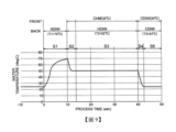
參閱圖9,說明關於從晶圓升溫工程至沖洗工程為止之間的晶圓溫度之推移的一例。在晶圓升溫工程(S1)中,係70℃之HDIW作為調溫液被供給至晶圓W的背面(BACK)。在從晶圓升溫工程(S1)開始經過10秒後,晶圓W之溫度,係達到約70℃。其後,在液膜形成工程(S2)中,係52℃之HDIW作為調溫液被供給至晶圓W的背面,且常溫(25℃)之藥液(CHM)被供給至晶圓W的表面(FRONT)。在從液膜形成工程(S2)開始約3秒後,晶圓溫度穩定於本處理時晶圓溫度即50℃。其後,在本處理工程(S3)亦即藥液處理工程中,係繼續供給52℃之HDIW至晶圓W的背面,且常溫(25℃)之藥液(CHM)被供給至晶圓W的表面。但是,亦如先前所述般,本處理工程(S3)中之晶圓旋轉數及藥液吐出流量,係比液膜形成工程(S2)時低。從本處理工程(S3)起進行大概17秒。其後,在晶圓降溫工程(S4)中,係24℃之CDIW被供給至晶圓W的背面,且晶圓W之溫度在約2秒內下降至常溫。在圖9之例子中,係在開始晶圓降溫工程(S4)的同時,24℃之CDIW作為沖洗液被供給至晶圓W的表面。該CDIW,係使晶圓W之溫度下降的冷卻液,並且亦為沖洗晶圓W的表面之藥液的沖洗液。在晶圓W之溫度穩定於常溫後,亦繼續供給24℃之CDIW作為沖洗液至晶圓W的表面,進行沖洗工程(S5)。在圖9之例子中,係晶圓降溫工程(S4)亦包含於沖洗工程(S5)的一部分。Referring to FIG. 9, an example of the change in wafer temperature from the wafer heating process to the rinsing process is described. In the wafer heating process (S1), 70°C HDIW is supplied as a temperature regulating liquid to the back side (BACK) of the wafer W. After 10 seconds from the start of the wafer heating process (S1), the temperature of the wafer W reaches about 70°C. Thereafter, in the liquid film forming process (S2), 52°C HDIW is supplied as a temperature regulating liquid to the back side of the wafer W, and a chemical solution (CHM) at room temperature (25°C) is supplied to the front side (FRONT) of the wafer W. About 3 seconds after the start of the liquid film forming process (S2), the wafer temperature stabilizes at 50°C, which is the wafer temperature during this process. Thereafter, in the present processing step (S3), i.e., the chemical liquid processing step, HDIW at 52°C is continuously supplied to the back side of the wafer W, and the chemical liquid (CHM) at room temperature (25°C) is supplied to the surface of the wafer W. However, as previously mentioned, the number of wafer rotations and the chemical liquid discharge flow rate in the present processing step (S3) are lower than those in the liquid film formation step (S2). The present processing step (S3) is performed for approximately 17 seconds. Thereafter, in the wafer cooling step (S4), CDIW at 24°C is supplied to the back side of the wafer W, and the temperature of the wafer W drops to room temperature in approximately 2 seconds. In the example of FIG. 9 , CDIW at 24°C is supplied to the surface of the wafer W as a rinse liquid at the same time as the wafer cooling step (S4) is started. The CDIW is a cooling liquid that lowers the temperature of the wafer W and is also a rinsing liquid for rinsing the surface of the wafer W. After the temperature of the wafer W is stabilized at room temperature, CDIW at 24°C is continuously supplied to the surface of the wafer W as a rinsing liquid to perform the rinsing process (S5). In the example of FIG. 9 , the wafer cooling process (S4) is also included as a part of the rinsing process (S5).
在上述實施形態中,雖係藉由各別不同之表面噴嘴41來供給不同的處理液,但並不限定於此。例如,亦可從1個表面噴嘴41供給即便藉由相同噴嘴供給亦不會發生問題之2種以上的處理液。又,在上述實施形態中,雖係從背面噴嘴51A、51B僅供給了晶圓W的溫度調節用之DIW,但亦可設成為如也可從背面噴嘴51A供給其他處理液例如藥液般的構成。另外,在從相同噴嘴供給複數種處理液的情況下,可藉由切換閥(或複數個開關閥)連接切換之複數個處理液供給機構,係並列地被連接於1個表面噴嘴41。由於像這樣的構成為習知,因此,在本說明書中,係不進行詳細說明。In the above-mentioned embodiment, different processing liquids are supplied through
其次,參閱圖10,簡單地說明關於基板處理系統1內之HDIW及CDIW的配管系統之一例。基板處理系統1之處理站3,係具有由上層3A及下層3B所構成的2層構造。在圖10中,符號71,係表示作為工廠設施的HDIW供給源,符號72,係表示作為工廠設施的CDIW供給源。Next, referring to FIG. 10 , an example of a piping system for HDIW and CDIW in the
在HDIW供給源71,係連接有HDIW管路711的上游端。HDIW管路711,係於分歧點712分歧成上層3A用之分歧管路713A與下層3B用之分歧管路713B。在分歧點712之上游側中,在HDIW管路711,係設置有開關閥710及溫度感測器716。分歧管路713A、713B,係在合流點714再次匯流而成為1個HDIW管路711。HDIW管路711之下游端,係被連接於工廠排放管線(DR)。在合流點714之下游側,係設置有背壓閥715。The
在CDIW供給源72,係連接有CDIW管路721的上游端。CDIW管路721,係於分歧點722分歧成上層3A用之分歧管路723A與下層3B用之分歧管路723B。在分歧點722之上游側中,在CDIW管路721,係設置有CO2
起泡器720及溫度感測器726。分歧管路723A、723B,係在合流點724再次匯流而成為1個CDIW管路721。CDIW管路721之下游端,係被連接於工廠排放管線(DR)。在分歧管路723A、723B之最下游部分(意味著比對最下游側的處理單元16之連接點更下游側的部分),係設置有壓力控制用的孔口727A、727B(固定節流器)。The upstream end of the
分歧管路713A(713B),係相當於圖3的流體迴路圖中之HDIW幹管23。分歧管路723A(723B),係相當於圖3的流體迴路圖中之CDIW幹管24。亦即,在圖10之例子中,係藉由調溫用DIW供給機構53A(在圖10中,係以虛線之方框所示),混合從分歧管路713A(713B)所取出的HDIW與從分歧管路723A(723B)所取出的CIWD並供給至背面噴嘴51A。圖10之調溫用DIW供給機構53A的構成,係與圖2之調溫用DIW供給機構53A的構成相同。雖逐一被設置於調溫用DIW供給機構53A、各處理單元16,但為了簡化圖面,在圖10,係僅表示1個。The
圖11,係表示基板處理系統1內之HDIW配管系統的其他例。在圖11中,係省略CDIW配管系統的記載。在該例子中,係HDIW管路803之上游端被連接於作為工廠設施的HDIW供給管線801。HDIW管路803,係於分歧點804分歧成上層3A用之分歧管路805A與下層3B用之分歧管路805B。在分歧點804之上游側中,在HDIW管路803,係設置有開關閥817及溫度感測器816。分歧管路805A、805B,係在合流點806再次匯流而成為1個HDIW管路803。在合流點806之下游側中,在HDIW管路803,係設置有開關閥807及止回閥808。HDIW管路803之下游端,係被連接於作為工廠設施系統之一部分的HDIW回流管線802。在合流點806與開關閥807之間,排放管路809從HDIW管路803分歧。在排放管路809,係設置有開關閥810。在基板處理系統1正常運作時,係開關閥807、817開啟且開關閥810關閉。在進行維護等之目的,在停止基板處理系統1之運作的情況下,係開關閥807、817關閉且開關閥810開啟,以排出管路內之DIW。在該例子中,係不同於圖10的例子,在HDIW管路803之下游端部,係未設置有背壓閥。FIG. 11 shows another example of the HDIW piping system in the
本次所揭示之實施形態,係在所有方面皆為例示,吾人應瞭解該等例示並非用以限制本發明。上述之實施形態,係亦可在不脫離添附之申請專利範圍及其主旨的情況下,以各種形態進行省略、置換、變更。The embodiments disclosed herein are illustrative in all aspects, and it should be understood that such illustrative embodiments are not intended to limit the present invention. The embodiments described above may be omitted, replaced, or modified in various forms without departing from the scope and gist of the attached patent application.
處理對象之基板,係不限定於半導體晶圓(晶圓W),亦可為玻璃基板、陶瓷基板等的半導體裝置製造之領域中所使用的任意基板。The substrate to be processed is not limited to a semiconductor wafer (wafer W), but may be any substrate used in the field of semiconductor device manufacturing, such as a glass substrate or a ceramic substrate.
W:基板 S1:基板升溫工程 S2:液膜形成工程 S3:藥液處理工程 S4:基板降溫工程W: Substrate S1: Substrate heating process S2: Liquid film formation process S3: Chemical liquid treatment process S4: Substrate cooling process
[圖1]基板處理裝置之一實施形態之基板處理系統的縱剖側視圖。 [圖2]表示被設置於於圖1之基板處理系統的處理單元之構成之一例的概略縱剖面圖。 [圖3]表示將調溫用DIW供給至處理單元之背面噴嘴的調溫用DIW供給機構之一例的配管系統等圖。 [圖4A]說明關於一實施形態之液處理之工程的作用圖。 [圖4B]說明關於一實施形態之液處理之工程的作用圖。 [圖4C]說明關於一實施形態之液處理之工程的作用圖。 [圖5A]說明關於一實施形態之液處理之工程的作用圖。 [圖5B]說明關於一實施形態之液處理之工程的作用圖。 [圖5C]說明關於一實施形態之液處理之工程的作用圖。 [圖6]說明關於一實施形態之液處理之工程的作用圖。 [圖7]說明關於一實施形態之液處理之工程的作用圖。 [圖8]說明關於一實施形態之液處理之工程的作用圖。 [圖9]說明關於從晶圓升溫工程至沖洗工程為止之間的晶圓溫度之推移之一例的曲線圖。 [圖10]概略地表示關於基板處理系統內之HDIW及CDIW配管系統之一例的配管系統等圖。 [圖11]概略地表示關於基板處理系統內之HDIW配管系統之其他例的配管系統等圖。[FIG. 1] A longitudinal sectional side view of a substrate processing system in an embodiment of a substrate processing device. [FIG. 2] A schematic longitudinal sectional view showing an example of the structure of a processing unit provided in the substrate processing system in FIG. 1. [FIG. 3] A diagram showing a piping system and the like of an example of a temperature-adjusting DIW supply mechanism for supplying temperature-adjusting DIW to a back nozzle of a processing unit. [FIG. 4A] A function diagram for explaining a liquid processing process in an embodiment. [FIG. 4B] A function diagram for explaining a liquid processing process in an embodiment. [FIG. 4C] A function diagram for explaining a liquid processing process in an embodiment. [FIG. 5A] A function diagram for explaining a liquid processing process in an embodiment. [FIG. 5B] A function diagram for explaining a liquid processing process in an embodiment. [FIG. 5C] A diagram for explaining the operation of a liquid treatment process in an implementation form. [FIG. 6] A diagram for explaining the operation of a liquid treatment process in an implementation form. [FIG. 7] A diagram for explaining the operation of a liquid treatment process in an implementation form. [FIG. 8] A diagram for explaining the operation of a liquid treatment process in an implementation form. [FIG. 9] A graph for explaining an example of the change in wafer temperature from the wafer heating process to the rinsing process. [FIG. 10] A diagram schematically showing a piping system, etc., of an example of an HDIW and CDIW piping system in a substrate processing system. [FIG. 11] A diagram schematically showing a piping system, etc., of another example of an HDIW piping system in a substrate processing system.
Claims (12)
Applications Claiming Priority (2)
| Application Number | Priority Date | Filing Date | Title |
|---|---|---|---|
| JP2019177637A JP7390837B2 (en) | 2019-09-27 | 2019-09-27 | Substrate processing method and substrate processing apparatus |
| JP2019-177637 | 2019-09-27 |
Publications (2)
| Publication Number | Publication Date |
|---|---|
| TW202125608A TW202125608A (en) | 2021-07-01 |
| TWI854027B true TWI854027B (en) | 2024-09-01 |
Family
ID=75120159
Family Applications (1)
| Application Number | Title | Priority Date | Filing Date |
|---|---|---|---|
| TW109131610A TWI854027B (en) | 2019-09-27 | 2020-09-15 | Substrate processing method and substrate processing device |
Country Status (5)
| Country | Link |
|---|---|
| US (2) | US11869777B2 (en) |
| JP (1) | JP7390837B2 (en) |
| KR (1) | KR102777132B1 (en) |
| CN (1) | CN112582302B (en) |
| TW (1) | TWI854027B (en) |
Families Citing this family (6)
| Publication number | Priority date | Publication date | Assignee | Title |
|---|---|---|---|---|
| JP7390837B2 (en) * | 2019-09-27 | 2023-12-04 | 東京エレクトロン株式会社 | Substrate processing method and substrate processing apparatus |
| CN114446765B (en) * | 2020-11-04 | 2025-11-18 | 中芯国际集成电路制造(上海)有限公司 | wet etching method |
| KR20240091300A (en) * | 2021-11-04 | 2024-06-21 | 도쿄엘렉트론가부시키가이샤 | Substrate processing method and substrate processing device |
| JP7735853B2 (en) * | 2021-12-23 | 2025-09-09 | 株式会社Sumco | Semiconductor wafer cleaning method and semiconductor wafer manufacturing method |
| JP2024076586A (en) * | 2022-11-25 | 2024-06-06 | 東京エレクトロン株式会社 | SUBSTRATE PROCESSING METHOD AND SUBSTRATE PROCESSING SYSTEM |
| US12599937B2 (en) * | 2024-01-23 | 2026-04-14 | Applied Materials, Inc. | Water-based, high-efficiency chemical reagent for substrate surface particle removal |
Citations (3)
| Publication number | Priority date | Publication date | Assignee | Title |
|---|---|---|---|---|
| TW201707132A (en) * | 2015-05-15 | 2017-02-16 | Tokyo Electron Ltd | Substrate processing apparatus, substrate processing method and storage medium |
| TW201824437A (en) * | 2016-12-28 | 2018-07-01 | 日商斯庫林集團股份有限公司 | Substrate processing apparatus and substrate processing method |
| US20190237322A1 (en) * | 2018-01-31 | 2019-08-01 | SCREEN Holdings Co., Ltd. | Substrate processing method and substrate processing apparatus |
Family Cites Families (28)
| Publication number | Priority date | Publication date | Assignee | Title |
|---|---|---|---|---|
| US20040065540A1 (en) * | 2002-06-28 | 2004-04-08 | Novellus Systems, Inc. | Liquid treatment using thin liquid layer |
| US6827814B2 (en) * | 2000-05-08 | 2004-12-07 | Tokyo Electron Limited | Processing apparatus, processing system and processing method |
| JP2003115474A (en) * | 2001-10-03 | 2003-04-18 | Ebara Corp | Substrate processing apparatus and method |
| JP4393071B2 (en) * | 2002-07-12 | 2010-01-06 | 東京エレクトロン株式会社 | Deposition method |
| JP5249915B2 (en) * | 2009-01-22 | 2013-07-31 | 東京エレクトロン株式会社 | Chemical treatment apparatus and chemical treatment method |
| KR101590661B1 (en) * | 2010-09-13 | 2016-02-01 | 도쿄엘렉트론가부시키가이샤 | Liquid processing apparatus, liquid processing method and storage medium |
| KR101733179B1 (en) * | 2010-10-15 | 2017-05-08 | 맛선 테크놀러지, 인코포레이티드 | Methods, apparatus and media for determining a shape of an irradiance pulse to which a workpiece is to be exposed |
| TWI480937B (en) * | 2011-01-06 | 2015-04-11 | 斯克林集團公司 | Substrate processing method and substrate processing device |
| JP5836906B2 (en) | 2012-04-26 | 2015-12-24 | 東京エレクトロン株式会社 | Substrate processing apparatus and substrate processing method |
| US20140273498A1 (en) * | 2013-03-15 | 2014-09-18 | Dainippon Screen Mfg. Co., Ltd. | Substrate processing apparatus and substrate processing method |
| US10062586B2 (en) | 2013-07-26 | 2018-08-28 | Tokyo Electron Limited | Chemical fluid processing apparatus and chemical fluid processing method |
| JP6191953B2 (en) * | 2013-09-02 | 2017-09-06 | 株式会社Screenホールディングス | Substrate processing method and substrate processing apparatus |
| KR102239421B1 (en) * | 2013-09-02 | 2021-04-12 | 가부시키가이샤 스크린 홀딩스 | Substrate processing method and substrate processing apparatus |
| JP6256828B2 (en) | 2013-10-10 | 2018-01-10 | 株式会社Screenホールディングス | Substrate processing method and substrate processing apparatus |
| JP6064875B2 (en) * | 2013-11-25 | 2017-01-25 | 東京エレクトロン株式会社 | Liquid processing apparatus, liquid processing method, and storage medium |
| US9460944B2 (en) * | 2014-07-02 | 2016-10-04 | SCREEN Holdings Co., Ltd. | Substrate treating apparatus and method of treating substrate |
| JP6489475B2 (en) | 2015-03-03 | 2019-03-27 | 株式会社Screenホールディングス | Substrate processing equipment |
| JP6517564B2 (en) | 2015-03-30 | 2019-05-22 | 株式会社Screenホールディングス | Substrate processing equipment |
| US10553421B2 (en) * | 2015-05-15 | 2020-02-04 | Tokyo Electron Limited | Substrate processing apparatus, substrate processing method and storage medium |
| JP6573520B2 (en) * | 2015-09-29 | 2019-09-11 | 株式会社Screenホールディングス | Substrate processing method and substrate processing apparatus |
| US10867814B2 (en) * | 2016-02-15 | 2020-12-15 | Tokyo Electron Limited | Liquid processing method, substrate processing apparatus, and storage medium |
| JP6765878B2 (en) * | 2016-07-06 | 2020-10-07 | 東京エレクトロン株式会社 | Substrate liquid treatment method and substrate liquid treatment equipment |
| JP6910164B2 (en) * | 2017-03-01 | 2021-07-28 | 東京エレクトロン株式会社 | Substrate processing equipment and substrate processing method |
| JP6896474B2 (en) * | 2017-03-27 | 2021-06-30 | 株式会社Screenホールディングス | Substrate processing equipment and substrate processing method |
| JP7034634B2 (en) * | 2017-08-31 | 2022-03-14 | 株式会社Screenホールディングス | Board processing method and board processing equipment |
| JP6953255B2 (en) * | 2017-09-21 | 2021-10-27 | 株式会社Screenホールディングス | Board processing method and board processing equipment |
| US11302525B2 (en) * | 2017-09-22 | 2022-04-12 | SCREEN Holdings Co., Ltd. | Substrate processing method and substrate processing apparatus |
| JP7390837B2 (en) * | 2019-09-27 | 2023-12-04 | 東京エレクトロン株式会社 | Substrate processing method and substrate processing apparatus |
-
2019
- 2019-09-27 JP JP2019177637A patent/JP7390837B2/en active Active
-
2020
- 2020-09-15 TW TW109131610A patent/TWI854027B/en active
- 2020-09-18 CN CN202010986383.XA patent/CN112582302B/en active Active
- 2020-09-21 KR KR1020200121714A patent/KR102777132B1/en active Active
- 2020-09-24 US US17/030,488 patent/US11869777B2/en active Active
-
2023
- 2023-11-27 US US18/519,519 patent/US12362202B2/en active Active
Patent Citations (3)
| Publication number | Priority date | Publication date | Assignee | Title |
|---|---|---|---|---|
| TW201707132A (en) * | 2015-05-15 | 2017-02-16 | Tokyo Electron Ltd | Substrate processing apparatus, substrate processing method and storage medium |
| TW201824437A (en) * | 2016-12-28 | 2018-07-01 | 日商斯庫林集團股份有限公司 | Substrate processing apparatus and substrate processing method |
| US20190237322A1 (en) * | 2018-01-31 | 2019-08-01 | SCREEN Holdings Co., Ltd. | Substrate processing method and substrate processing apparatus |
Also Published As
| Publication number | Publication date |
|---|---|
| US20240096654A1 (en) | 2024-03-21 |
| JP7390837B2 (en) | 2023-12-04 |
| US12362202B2 (en) | 2025-07-15 |
| JP2021057411A (en) | 2021-04-08 |
| US20210098271A1 (en) | 2021-04-01 |
| TW202125608A (en) | 2021-07-01 |
| KR20210037554A (en) | 2021-04-06 |
| US11869777B2 (en) | 2024-01-09 |
| CN112582302A (en) | 2021-03-30 |
| KR102777132B1 (en) | 2025-03-05 |
| CN112582302B (en) | 2026-01-13 |
Similar Documents
| Publication | Publication Date | Title |
|---|---|---|
| TWI854027B (en) | Substrate processing method and substrate processing device | |
| TWI861286B (en) | Substrate processing device and substrate processing method | |
| KR101527645B1 (en) | Substrate processing apparatus and substrate processing method | |
| US9437464B2 (en) | Substrate treating method for treating substrates with treating liquids | |
| CN114551304B (en) | Substrate processing apparatus | |
| US7914626B2 (en) | Liquid processing method and liquid processing apparatus | |
| JP6480009B2 (en) | Substrate liquid processing apparatus, substrate liquid processing method, and storage medium | |
| KR20150009449A (en) | Substrate processing apparatus and substrate processing method | |
| JP6728358B2 (en) | Substrate processing apparatus, substrate processing method and storage medium | |
| US8286580B2 (en) | Apparatus and method for treating substrate | |
| EP1791161B1 (en) | Liquid processing method and liquid processing apparatus | |
| KR20090012703A (en) | Substrate Cleaning Apparatus and Method | |
| JP7638138B2 (en) | SUBSTRATE PROCESSING APPARATUS AND SUBSTRATE PROCESSING METHOD | |
| JP2024011170A (en) | Substrate processing equipment and substrate processing method | |
| JP7816874B2 (en) | Substrate processing apparatus and substrate processing method | |
| WO2025239240A1 (en) | Substrate processing device and substrate processing method | |
| JP2024076586A (en) | SUBSTRATE PROCESSING METHOD AND SUBSTRATE PROCESSING SYSTEM | |
| KR20240129571A (en) | Substrate processing apparatus and substrate processing method | |
| JP2025110732A (en) | SUBSTRATE PROCESSING APPARATUS AND SUBSTRATE PROCESSING METHOD | |
| JP2015023047A (en) | Substrate processing apparatus and substrate processing method | |
| KR20090054031A (en) | Substrate Drying Equipment |