TWI830779B - Manufacturing method and package of cylindrical sputtering target material package - Google Patents
Manufacturing method and package of cylindrical sputtering target material package Download PDFInfo
- Publication number
- TWI830779B TWI830779B TW108133650A TW108133650A TWI830779B TW I830779 B TWI830779 B TW I830779B TW 108133650 A TW108133650 A TW 108133650A TW 108133650 A TW108133650 A TW 108133650A TW I830779 B TWI830779 B TW I830779B
- Authority
- TW
- Taiwan
- Prior art keywords
- sheet
- sputtering target
- cylindrical
- cylindrical sputtering
- buffer material
- Prior art date
Links
- 238000005477 sputtering target Methods 0.000 title claims abstract description 198
- 239000013077 target material Substances 0.000 title claims abstract description 36
- 238000004519 manufacturing process Methods 0.000 title claims abstract description 28
- 239000000463 material Substances 0.000 claims abstract description 222
- 238000000034 method Methods 0.000 claims abstract description 18
- 238000004806 packaging method and process Methods 0.000 claims abstract description 12
- 230000003139 buffering effect Effects 0.000 claims description 32
- 230000001681 protective effect Effects 0.000 claims description 26
- 239000000853 adhesive Substances 0.000 claims description 10
- 230000001070 adhesive effect Effects 0.000 claims description 10
- 238000012856 packing Methods 0.000 claims description 8
- 239000010410 layer Substances 0.000 description 115
- -1 polyethylene terephthalate Polymers 0.000 description 15
- 239000000428 dust Substances 0.000 description 14
- 238000004544 sputter deposition Methods 0.000 description 11
- 238000005520 cutting process Methods 0.000 description 9
- 230000000694 effects Effects 0.000 description 9
- 238000003466 welding Methods 0.000 description 9
- 229920000139 polyethylene terephthalate Polymers 0.000 description 8
- 239000005020 polyethylene terephthalate Substances 0.000 description 8
- XLOMVQKBTHCTTD-UHFFFAOYSA-N Zinc monoxide Chemical compound [Zn]=O XLOMVQKBTHCTTD-UHFFFAOYSA-N 0.000 description 6
- QVGXLLKOCUKJST-UHFFFAOYSA-N atomic oxygen Chemical compound [O] QVGXLLKOCUKJST-UHFFFAOYSA-N 0.000 description 5
- 229910052751 metal Inorganic materials 0.000 description 5
- 239000002184 metal Substances 0.000 description 5
- 239000001301 oxygen Substances 0.000 description 5
- 229910052760 oxygen Inorganic materials 0.000 description 5
- 239000005022 packaging material Substances 0.000 description 5
- 229920005989 resin Polymers 0.000 description 5
- 239000011347 resin Substances 0.000 description 5
- 239000004698 Polyethylene Substances 0.000 description 4
- 239000004743 Polypropylene Substances 0.000 description 4
- 229920001328 Polyvinylidene chloride Polymers 0.000 description 4
- 229910052782 aluminium Inorganic materials 0.000 description 4
- 239000010949 copper Substances 0.000 description 4
- 229920000573 polyethylene Polymers 0.000 description 4
- 229920001155 polypropylene Polymers 0.000 description 4
- 239000005033 polyvinylidene chloride Substances 0.000 description 4
- 239000000126 substance Substances 0.000 description 4
- 238000009461 vacuum packaging Methods 0.000 description 4
- 229910000838 Al alloy Inorganic materials 0.000 description 3
- 239000004677 Nylon Substances 0.000 description 3
- 229910045601 alloy Inorganic materials 0.000 description 3
- 239000000956 alloy Substances 0.000 description 3
- XAGFODPZIPBFFR-UHFFFAOYSA-N aluminium Chemical compound [Al] XAGFODPZIPBFFR-UHFFFAOYSA-N 0.000 description 3
- 230000000052 comparative effect Effects 0.000 description 3
- 229910052802 copper Inorganic materials 0.000 description 3
- 229920001778 nylon Polymers 0.000 description 3
- 229910052721 tungsten Inorganic materials 0.000 description 3
- 238000004804 winding Methods 0.000 description 3
- 239000011787 zinc oxide Substances 0.000 description 3
- 239000004925 Acrylic resin Substances 0.000 description 2
- 229920000178 Acrylic resin Polymers 0.000 description 2
- 229920000219 Ethylene vinyl alcohol Polymers 0.000 description 2
- GYHNNYVSQQEPJS-UHFFFAOYSA-N Gallium Chemical compound [Ga] GYHNNYVSQQEPJS-UHFFFAOYSA-N 0.000 description 2
- VYPSYNLAJGMNEJ-UHFFFAOYSA-N Silicium dioxide Chemical compound O=[Si]=O VYPSYNLAJGMNEJ-UHFFFAOYSA-N 0.000 description 2
- 239000000654 additive Substances 0.000 description 2
- 230000000996 additive effect Effects 0.000 description 2
- 239000012790 adhesive layer Substances 0.000 description 2
- 239000002390 adhesive tape Substances 0.000 description 2
- 229920006378 biaxially oriented polypropylene Polymers 0.000 description 2
- 239000011127 biaxially oriented polypropylene Substances 0.000 description 2
- 230000003749 cleanliness Effects 0.000 description 2
- 230000006866 deterioration Effects 0.000 description 2
- JAONJTDQXUSBGG-UHFFFAOYSA-N dialuminum;dizinc;oxygen(2-) Chemical compound [O-2].[O-2].[O-2].[O-2].[O-2].[Al+3].[Al+3].[Zn+2].[Zn+2] JAONJTDQXUSBGG-UHFFFAOYSA-N 0.000 description 2
- 238000010894 electron beam technology Methods 0.000 description 2
- 229910052733 gallium Inorganic materials 0.000 description 2
- 229920001903 high density polyethylene Polymers 0.000 description 2
- 239000004700 high-density polyethylene Substances 0.000 description 2
- 239000011261 inert gas Substances 0.000 description 2
- 229920001684 low density polyethylene Polymers 0.000 description 2
- 239000004702 low-density polyethylene Substances 0.000 description 2
- 230000000873 masking effect Effects 0.000 description 2
- 150000002739 metals Chemical class 0.000 description 2
- 229910052750 molybdenum Inorganic materials 0.000 description 2
- 229910052759 nickel Inorganic materials 0.000 description 2
- 229910052758 niobium Inorganic materials 0.000 description 2
- 239000005026 oriented polypropylene Substances 0.000 description 2
- 230000003647 oxidation Effects 0.000 description 2
- 238000007254 oxidation reaction Methods 0.000 description 2
- 230000035699 permeability Effects 0.000 description 2
- 238000003860 storage Methods 0.000 description 2
- 229910052719 titanium Inorganic materials 0.000 description 2
- 238000002834 transmittance Methods 0.000 description 2
- XLYOFNOQVPJJNP-UHFFFAOYSA-N water Substances O XLYOFNOQVPJJNP-UHFFFAOYSA-N 0.000 description 2
- RYGMFSIKBFXOCR-UHFFFAOYSA-N Copper Chemical compound [Cu] RYGMFSIKBFXOCR-UHFFFAOYSA-N 0.000 description 1
- 229910052779 Neodymium Inorganic materials 0.000 description 1
- 238000009825 accumulation Methods 0.000 description 1
- PNEYBMLMFCGWSK-UHFFFAOYSA-N aluminium oxide Inorganic materials [O-2].[O-2].[O-2].[Al+3].[Al+3] PNEYBMLMFCGWSK-UHFFFAOYSA-N 0.000 description 1
- 230000015572 biosynthetic process Effects 0.000 description 1
- 238000005219 brazing Methods 0.000 description 1
- 238000005266 casting Methods 0.000 description 1
- 239000000919 ceramic Substances 0.000 description 1
- 230000008859 change Effects 0.000 description 1
- 229910052804 chromium Inorganic materials 0.000 description 1
- 239000002131 composite material Substances 0.000 description 1
- 238000011109 contamination Methods 0.000 description 1
- 238000010586 diagram Methods 0.000 description 1
- 230000005611 electricity Effects 0.000 description 1
- UFRKOOWSQGXVKV-UHFFFAOYSA-N ethene;ethenol Chemical compound C=C.OC=C UFRKOOWSQGXVKV-UHFFFAOYSA-N 0.000 description 1
- 239000004715 ethylene vinyl alcohol Substances 0.000 description 1
- 229910052738 indium Inorganic materials 0.000 description 1
- APFVFJFRJDLVQX-UHFFFAOYSA-N indium atom Chemical compound [In] APFVFJFRJDLVQX-UHFFFAOYSA-N 0.000 description 1
- AMGQUBHHOARCQH-UHFFFAOYSA-N indium;oxotin Chemical compound [In].[Sn]=O AMGQUBHHOARCQH-UHFFFAOYSA-N 0.000 description 1
- 229910052742 iron Inorganic materials 0.000 description 1
- 230000007774 longterm Effects 0.000 description 1
- 229910052749 magnesium Inorganic materials 0.000 description 1
- 239000012528 membrane Substances 0.000 description 1
- 238000012986 modification Methods 0.000 description 1
- 230000004048 modification Effects 0.000 description 1
- 239000002114 nanocomposite Substances 0.000 description 1
- 229910052763 palladium Inorganic materials 0.000 description 1
- 239000002245 particle Substances 0.000 description 1
- 230000002093 peripheral effect Effects 0.000 description 1
- 229910052697 platinum Inorganic materials 0.000 description 1
- 229920003207 poly(ethylene-2,6-naphthalate) Polymers 0.000 description 1
- 229920001707 polybutylene terephthalate Polymers 0.000 description 1
- 229920001225 polyester resin Polymers 0.000 description 1
- 239000011112 polyethylene naphthalate Substances 0.000 description 1
- 229920000098 polyolefin Polymers 0.000 description 1
- 229920005672 polyolefin resin Polymers 0.000 description 1
- 239000004800 polyvinyl chloride Substances 0.000 description 1
- 230000008569 process Effects 0.000 description 1
- 229910052707 ruthenium Inorganic materials 0.000 description 1
- 238000007665 sagging Methods 0.000 description 1
- 238000007789 sealing Methods 0.000 description 1
- 229910052710 silicon Inorganic materials 0.000 description 1
- 239000000377 silicon dioxide Substances 0.000 description 1
- 229910052709 silver Inorganic materials 0.000 description 1
- 229910000679 solder Inorganic materials 0.000 description 1
- 125000006850 spacer group Chemical group 0.000 description 1
- 230000003068 static effect Effects 0.000 description 1
- 238000003756 stirring Methods 0.000 description 1
- 229910052715 tantalum Inorganic materials 0.000 description 1
- WFKWXMTUELFFGS-UHFFFAOYSA-N tungsten Chemical compound [W] WFKWXMTUELFFGS-UHFFFAOYSA-N 0.000 description 1
- 239000010937 tungsten Substances 0.000 description 1
- 239000011701 zinc Substances 0.000 description 1
- 229910052726 zirconium Inorganic materials 0.000 description 1
Images


Classifications
-
- B—PERFORMING OPERATIONS; TRANSPORTING
- B65—CONVEYING; PACKING; STORING; HANDLING THIN OR FILAMENTARY MATERIAL
- B65D—CONTAINERS FOR STORAGE OR TRANSPORT OF ARTICLES OR MATERIALS, e.g. BAGS, BARRELS, BOTTLES, BOXES, CANS, CARTONS, CRATES, DRUMS, JARS, TANKS, HOPPERS, FORWARDING CONTAINERS; ACCESSORIES, CLOSURES, OR FITTINGS THEREFOR; PACKAGING ELEMENTS; PACKAGES
- B65D81/00—Containers, packaging elements, or packages, for contents presenting particular transport or storage problems, or adapted to be used for non-packaging purposes after removal of contents
- B65D81/02—Containers, packaging elements, or packages, for contents presenting particular transport or storage problems, or adapted to be used for non-packaging purposes after removal of contents specially adapted to protect contents from mechanical damage
- B65D81/03—Wrappers or envelopes with shock-absorbing properties, e.g. bubble films
-
- B—PERFORMING OPERATIONS; TRANSPORTING
- B65—CONVEYING; PACKING; STORING; HANDLING THIN OR FILAMENTARY MATERIAL
- B65D—CONTAINERS FOR STORAGE OR TRANSPORT OF ARTICLES OR MATERIALS, e.g. BAGS, BARRELS, BOTTLES, BOXES, CANS, CARTONS, CRATES, DRUMS, JARS, TANKS, HOPPERS, FORWARDING CONTAINERS; ACCESSORIES, CLOSURES, OR FITTINGS THEREFOR; PACKAGING ELEMENTS; PACKAGES
- B65D85/00—Containers, packaging elements or packages, specially adapted for particular articles or materials
- B65D85/20—Containers, packaging elements or packages, specially adapted for particular articles or materials for incompressible or rigid rod-shaped or tubular articles
-
- C—CHEMISTRY; METALLURGY
- C23—COATING METALLIC MATERIAL; COATING MATERIAL WITH METALLIC MATERIAL; CHEMICAL SURFACE TREATMENT; DIFFUSION TREATMENT OF METALLIC MATERIAL; COATING BY VACUUM EVAPORATION, BY SPUTTERING, BY ION IMPLANTATION OR BY CHEMICAL VAPOUR DEPOSITION, IN GENERAL; INHIBITING CORROSION OF METALLIC MATERIAL OR INCRUSTATION IN GENERAL
- C23C—COATING METALLIC MATERIAL; COATING MATERIAL WITH METALLIC MATERIAL; SURFACE TREATMENT OF METALLIC MATERIAL BY DIFFUSION INTO THE SURFACE, BY CHEMICAL CONVERSION OR SUBSTITUTION; COATING BY VACUUM EVAPORATION, BY SPUTTERING, BY ION IMPLANTATION OR BY CHEMICAL VAPOUR DEPOSITION, IN GENERAL
- C23C14/00—Coating by vacuum evaporation, by sputtering or by ion implantation of the coating forming material
- C23C14/22—Coating by vacuum evaporation, by sputtering or by ion implantation of the coating forming material characterised by the process of coating
- C23C14/34—Sputtering
Landscapes
- Engineering & Computer Science (AREA)
- Mechanical Engineering (AREA)
- Chemical & Material Sciences (AREA)
- Chemical Kinetics & Catalysis (AREA)
- Materials Engineering (AREA)
- Metallurgy (AREA)
- Organic Chemistry (AREA)
- Buffer Packaging (AREA)
- Physical Vapour Deposition (AREA)
Abstract
本發明提供一種捆包體的製造方法,所述捆包體是利用片狀緩衝材將圓筒狀濺鍍靶材捆包而成,且所述捆包體的製造方法中,能夠於將圓筒狀濺鍍靶材橫置的狀態下容易地拆包。一種捆包體的製造方法,所述捆包體是利用片狀緩衝材將圓筒狀濺鍍靶材捆包而成,所述捆包體的製造方法中,利用至少兩層片狀緩衝材覆蓋圓筒狀濺鍍靶材的圓筒部,於該圓筒狀濺鍍靶材的圓筒部的包含圓周方向的剖面上,使片狀緩衝材的兩端部以該圓筒部的圓周的一半以下的長度重合、或對接,藉此進行捆包。The present invention provides a method for manufacturing a package in which a cylindrical sputtering target is packaged using a sheet-like buffer material, and in the method of manufacturing the package, the cylindrical target material can be packed into a package. The cylindrical sputtering target can be easily unpacked when placed horizontally. A method of manufacturing a package body, wherein the package body is formed by packaging a cylindrical sputtering target material with a sheet-shaped buffer material. In the manufacturing method of the package body, at least two layers of sheet-shaped buffer materials are used. Covering the cylindrical part of the cylindrical sputtering target, on the cross section of the cylindrical part of the cylindrical sputtering target including the circumferential direction, the two ends of the sheet-like buffer material are aligned with the circumference of the cylindrical part Less than half of the length overlaps or butts together for bundling.
Description
本發明是有關於一種圓筒狀濺鍍靶材的捆包體的製造方法,更詳細而言,是有關於一種利用片狀緩衝材將圓筒狀濺鍍靶材捆包而成的捆包體的製造方法、以及該捆包體。The present invention relates to a method for manufacturing a package body of a cylindrical sputtering target material. More specifically, it relates to a package in which a cylindrical sputtering target material is packaged using a sheet buffer material. The manufacturing method of the body and the packaging body.
圓筒狀濺鍍靶材(亦稱為圓筒型濺鍍靶材或旋轉濺鍍靶材)的主體部具有圓筒狀的形狀(以下,亦將具有圓筒狀的形狀的主體部稱為圓筒部)。藉由一面使圓筒狀濺鍍靶材旋轉一面對圓筒部的表面進行濺鍍,能夠於與圓筒狀濺鍍靶材相向地搬送的對象物上形成源自被濺鍍的材料的膜。The main body of a cylindrical sputtering target (also called a cylindrical sputtering target or a rotating sputtering target) has a cylindrical shape (hereinafter, the main body having a cylindrical shape is also referred to as cylindrical part). By performing sputtering on the surface of the cylindrical portion while rotating the cylindrical sputtering target, it is possible to form a sputtered material derived from the object being conveyed opposite the cylindrical sputtering target. membrane.
圓筒狀濺鍍靶材一般利用保護膜加以保護,由保護膜保護的圓筒狀靶材於利用片狀緩衝材進行了捆包的狀態下流通,並於該狀態下被搬運、保管等。圓筒狀濺鍍靶材藉由利用片狀緩衝材捆包而得到保護,藉此,能夠防止因衝擊等而於濺鍍靶材的表面(特別是作為濺鍍面的圓筒部表面)產生損傷。Cylindrical sputtering targets are generally protected with a protective film. The cylindrical target protected by the protective film is distributed in a state of being packaged with a sheet-like buffer material, and is transported, stored, etc. in this state. The cylindrical sputtering target is protected by being packed with a sheet-shaped buffer material. This prevents impact, etc. from occurring on the surface of the sputtering target (especially the surface of the cylindrical portion that is the sputtering surface). damage.
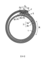
更詳細而言,如圖6(a)及圖6(b)所示,於現有的圓筒狀濺鍍靶材的捆包體70中,圓筒狀濺鍍靶材61藉由如下方式進行固定並捆包:將一片片狀緩衝材63沿圓周方向R捲繞兩周(於圖示的形態中,為了容易判別,於圓筒狀濺鍍靶材61與片狀緩衝材63之間以及片狀緩衝材63的層間示出間隙。該間隙可存在亦可不存在),並遍及長度方向L利用膠帶67(於單面上具有接著層)將片狀緩衝材63的圓周方向的外側端部E(沿著長度方向L延伸的捲繞結束端部)接著於其下方的片狀緩衝材63。再者,於圓筒狀濺鍍靶材61的長度方向的兩端部,將多餘的片狀緩衝材63適當折疊並固定(未圖示),從而將圓筒狀濺鍍靶材61捆包。作為片狀緩衝材63,使用氣泡緩衝材。More specifically, as shown in FIGS. 6(a) and 6(b) , in the conventional cylindrical
[發明所欲解決之課題]
於所述現有的圓筒狀濺鍍靶材的捆包體中,為了提高耐衝擊性(或緩衝(cushion)性),片狀緩衝材並非捲繞一周,而是如圖6(b)所示般捲繞兩周。關於該現有的圓筒狀濺鍍靶材的捆包體70,由於片狀緩衝材63捲繞於圓筒狀濺鍍靶材61上兩周,因此於拆包時僅剝離膠帶67無法將圓筒狀濺鍍靶材61自片狀緩衝材63中立即取出,因此,需要將捲繞兩周的片狀緩衝材63展開並取出圓筒狀濺鍍靶材61。長條的圓筒狀濺鍍靶材61難以藉由自重而自由移動,因此將圓筒狀濺鍍靶材61橫置並於片狀緩衝材63上轉動,藉此能夠將捲繞兩周的片狀緩衝材63展開。然而,若以此種方式拆包,則圓筒狀濺鍍靶材61最終是於一片厚度的片狀緩衝材63上轉動,因此,擔心成為濺鍍面的濺鍍靶材61的圓筒部表面受到損傷。圓筒狀濺鍍靶材61越長(即,越重),則所述擔心越顯著。因此,長條的圓筒狀濺鍍靶材的捆包體藉由如下方式拆包:於將圓筒狀濺鍍靶材61橫置的狀態下(不使其旋轉),利用切刀(cutter)將捲繞兩周的片狀緩衝材63一起(於圖6(b)中以虛線C示意性地表示切斷部)切斷,並遍及長度方向L切開。然而,若以此種方式拆包,則於利用切刀進行切斷、切開時,擔心濺鍍靶材61的圓筒部表面被切刀損傷。進而,於利用切刀進行切斷、切開時,可能產生源自片狀緩衝材63的灰塵,例如於無塵室(clean room)內拆包(將片狀緩衝材63切斷、切開)的情況下,可能會導致使無塵室內的清潔度降低的問題。[Problem to be solved by the invention]
In the conventional cylindrical sputtering target package, in order to improve the impact resistance (or cushioning properties), the sheet-like buffer material is not wound once, but as shown in Figure 6(b) It is like coiling twice. Regarding the conventional cylindrical
本發明是鑒於所述現有的課題而成者,目的在於提供一種捆包體的製造方法以及捆包體,所述捆包體是利用片狀緩衝材將圓筒狀濺鍍靶材捆包而成,且所述捆包體的製造方法中,能夠於將圓筒狀濺鍍靶材橫置的狀態下容易地拆包。The present invention was made in view of the above-mentioned conventional problems, and an object thereof is to provide a method of manufacturing a package in which a cylindrical sputtering target material is packaged using a sheet-like buffer material, and a package. In addition, in the manufacturing method of the package, the cylindrical sputtering target can be easily unpacked in a state where the cylindrical sputtering target is placed horizontally.
[解決課題之手段] 根據本發明,提供一種捆包體的製造方法,所述捆包體是利用片狀緩衝材將圓筒狀濺鍍靶材捆包而成,所述捆包體的製造方法中,利用至少兩層片狀緩衝材覆蓋圓筒狀濺鍍靶材的圓筒部,於該圓筒狀濺鍍靶材的圓筒部的包含圓周方向的剖面上,使片狀緩衝材的兩端部以該圓筒部的圓周的一半以下的長度重合、或對接,藉此進行捆包。[Means to solve the problem] According to the present invention, there is provided a method of manufacturing a package in which a cylindrical sputtering target is packed using a sheet-like buffer material, wherein at least two The sheet-like buffer material covers the cylindrical part of the cylindrical sputtering target, and in the cross section of the cylindrical part of the cylindrical sputtering target including the circumferential direction, the two ends of the sheet-like buffer material are aligned with the Packing is performed by overlapping or butting the lengths of less than half of the circumference of the cylindrical portion.
另外,根據本發明,提供一種捆包體,其是利用片狀緩衝材將圓筒狀濺鍍靶材捆包而成,圓筒狀濺鍍靶材的圓筒部由至少兩層片狀緩衝材覆蓋,於該圓筒狀濺鍍靶材的圓筒部的包含圓周方向的剖面上,片狀緩衝材的兩端部以該圓筒部的圓周的一半以下的長度重合、或對接。In addition, according to the present invention, there is provided a packaging body in which a cylindrical sputtering target is packed with a sheet-like buffer material, and the cylindrical portion of the cylindrical sputtering target is composed of at least two layers of sheet-like buffering materials. The material covers the cylindrical sputtering target, and on the cross section including the circumferential direction of the cylindrical part of the cylindrical sputtering target, both ends of the sheet-like buffer material overlap or butt together by a length less than half of the circumference of the cylindrical part.
再者,本發明中,術語「捆包」亦能夠理解為與「被覆」或「包裝」相同的含義。另外,本發明中,術語「對接」是指片狀緩衝材的兩端部的端面彼此接觸(抵接)或者接近。本發明中,術語「圓周方向」是指圓筒狀濺鍍靶材的圓筒部的相對於中心軸而言的圓周方向,於圖中以符號「R」表示。本發明中,術語「包含圓周方向的剖面」是指於包含該圓周方向的平面上切斷圓筒狀濺鍍靶材的圓筒部時的剖面,換言之,是指圓筒狀濺鍍靶材的圓筒部的相對於中心軸垂直的剖面。Furthermore, in the present invention, the term "packing" can also be understood to have the same meaning as "covering" or "packaging". In addition, in the present invention, the term "butt" means that the end surfaces of both ends of the sheet-shaped buffer material are in contact with (butt against) each other or are close to each other. In the present invention, the term "circumferential direction" refers to the circumferential direction of the cylindrical portion of the cylindrical sputtering target with respect to the central axis, and is represented by the symbol "R" in the figure. In the present invention, the term "cross section including the circumferential direction" refers to the cross section when the cylindrical portion of the cylindrical sputtering target is cut on a plane including the circumferential direction. In other words, it refers to the cylindrical sputtering target. The cross section of the cylindrical part perpendicular to the central axis.
於本發明的一個形態中,所述片狀緩衝材可藉由折疊而形成兩層或兩層以上的層。In one aspect of the present invention, the sheet-like buffer material can be folded to form two or more layers.
於本發明的一個形態中,所述片狀緩衝材的兩端部可藉由該些中的一端部的外側面與另一端部的內側面接觸而重合。或者,所述片狀緩衝材的兩端部可藉由該些中的一端部的內側面與另一端部的內側面接觸而重合。In one aspect of the present invention, both ends of the sheet-shaped buffer material can be overlapped by the outer surface of one end being in contact with the inner surface of the other end. Alternatively, both ends of the sheet-shaped buffer material may be overlapped by the inner surface of one end being in contact with the inner surface of the other end.
於本發明的一個形態中,所述片狀緩衝材的兩端部可於所述圓筒狀濺鍍靶材的長度方向上不連續地相互固定。In one aspect of the present invention, both ends of the sheet-shaped buffer material may be discontinuously fixed to each other in the longitudinal direction of the cylindrical sputtering target.
於本發明的一個形態中,所述片狀緩衝材的兩端部可藉由選自由膠帶(tape)、接著劑及黏著劑所組成的群組中的至少一個而相互固定。In one aspect of the present invention, both ends of the sheet-shaped buffer material can be fixed to each other by at least one selected from the group consisting of tape, adhesive, and adhesive.
於本發明的一個形態中,所述片狀緩衝材可為氣泡緩衝材。In one aspect of the present invention, the sheet-shaped buffer material may be a bubble buffer material.
於本發明的一個形態中,所述圓筒狀濺鍍靶材可具有500 mm以上的長度,且具有20 kg以上的質量。In one aspect of the present invention, the cylindrical sputtering target may have a length of 500 mm or more and a mass of 20 kg or more.
於本發明的一個形態中,可於所述圓筒狀濺鍍靶材與所述片狀緩衝材之間存在保護膜。In one aspect of the present invention, a protective film may be present between the cylindrical sputtering target and the sheet-like buffer material.
[發明的效果] 根據本發明,提供一種捆包體的製造方法,所述捆包體是利用片狀緩衝材將圓筒狀濺鍍靶材捆包而成,於所述捆包體的製造方法中,利用至少兩層片狀緩衝材覆蓋圓筒狀濺鍍靶材的圓筒部,於該圓筒狀濺鍍靶材的圓筒部的包含圓周方向的剖面上,使片狀緩衝材的兩端部以該圓筒部的圓周的一半以下的長度重合、或對接,藉此進行捆包,藉此能夠於將圓筒狀濺鍍靶材橫置的狀態下容易地拆包。另外,根據本發明,亦提供一種具有與該製造方法對應的構成的捆包體。[Effects of the invention] According to the present invention, there is provided a method for manufacturing a package in which a cylindrical sputtering target is packed with a sheet-like buffer material. In the method for manufacturing the package, at least Two layers of sheet-like buffering materials cover the cylindrical portion of the cylindrical sputtering target. On the cross section of the cylindrical portion of the cylindrical sputtering target including the circumferential direction, the two ends of the sheet-like buffering materials are The cylindrical portion is packaged by overlapping or butting less than half of its circumference, so that the cylindrical sputtering target can be easily unpacked in a state where the cylindrical sputtering target is laid horizontally. In addition, according to the present invention, there is also provided a package body having a structure corresponding to the manufacturing method.
以下,一面參照圖式一面對本發明的若干實施形態進行詳細敘述,但本發明並不限定於該些實施形態。Hereinafter, some embodiments of the present invention will be described in detail with reference to the drawings, but the present invention is not limited to these embodiments.
(實施形態1)
如圖1(a)及圖1(b)所示,本實施形態是有關於一種如下形態,其為利用片狀緩衝材3將圓筒狀濺鍍靶材1捆包而成的捆包體10及其製造方法,圓筒狀濺鍍靶材1的圓筒部由至少兩層片狀緩衝材3覆蓋,於圓筒狀濺鍍靶材1的圓筒部的包含圓周方向的剖面上,片狀緩衝材3的兩端部對接。再者,於圖示的形態中,為了容易判別,於圓筒狀濺鍍靶材1與片狀緩衝材3之間以及片狀緩衝材3的層間示出了間隙,但該間隙可存在亦可不存在。另外,於圖1(a)及圖1(b)所示的形態中,作為圓筒狀濺鍍靶材1,僅圖示了作為其主體部的圓筒部,但可如參照圖2(a)~圖2(d)於後文敘述般,於圓筒部的長度方向兩端部的一者或兩者具有接合器(adapter)等。(Embodiment 1)
As shown in FIGS. 1(a) and 1(b) , this embodiment relates to a package body in which the cylindrical
更詳細而言,於圖1(b)中,作為片狀緩衝材3,使用個別地分離的至少兩層(利用與層數為相同數量的片材(sheet)形成層。例如,並非由一片片材形成兩層,而是使用兩片片材形成兩層。於圖示的形態中為內側層3a及外側層3b這兩層),於包含圓周方向的剖面上,內側層3a具有兩端部A1、A2,外側層3b具有兩端部B1、B2。而且,重疊兩層的片狀緩衝材3的一端部A1、B1與另一端部A2、B2對接。然而,本發明不限定於圖示的形態,片狀緩衝材3可形成分別分離的三層以上的層,且片狀緩衝材3於重疊三層以上的狀態下,包含圓周方向的剖面上的兩端部對接。More specifically, in FIG. 1( b ), as the sheet-
本發明中,所謂片狀緩衝材的兩端部「對接」,是指兩端部的端面彼此抵接或接近,例如可應用後述的固定方法來實現。於圖1(b)中,片狀緩衝材3的一端部A1、B1的端面與另一端部A2、B2的端面抵接,但只要能夠充分保護圓筒狀靶材,則亦可於片狀緩衝材3的兩端部的端面間設置間隙而使其相互接近。兩端部的端面彼此是抵接還是接近亦可於各層不同(例如於兩層的情況下,可為內側層3a的端面(A1、A2)彼此抵接且外側層3b的端面(B1、B2)彼此抵接,亦可為內側層3a的端面彼此抵接且外側層3b的端面彼此接近,亦可為內側層3a的端面彼此接近且外側層3b的端面彼此抵接,亦可為內側層3a的端面彼此接近且外側層3b的端面彼此接近)。於多層中存在所述間隙的情況下,各層中的端面間的間隙實質上可相同亦可不同。端面間的間隙可連續存在,亦可不連續地存在,於不連續地存在的情況下,例如亦可僅於未固定的部位存在間隙。端面間的間隙為20 mm以下,較佳為15 mm以下,更佳為10 mm以下,進而佳為5 mm以下。In the present invention, the "butt" of the two ends of the sheet-shaped buffer material means that the end surfaces of the two ends are in contact with or close to each other. For example, this can be achieved by applying a fixing method described below. In FIG. 1( b ), the end surfaces of one end portion A1 and B1 of the sheet-shaped
進而,於本實施形態中,如圖1(a)所示,片狀緩衝材3的兩端部(於圖示的形態中,代表性的是外側層3b的端部B1與端部B2)於圓筒狀濺鍍靶材1的長度方向L上不連續地例如藉由膠帶(通常於單面上具有接著層,但不限定於此)5而相互接著並固定。固定方法不限定於所述膠帶,例如可應用選自由膠帶、接著劑及黏著劑所組成的群組中的至少一個。作為固定方法,雖然熔接的較佳性比該些差,但亦能夠應用熔接。Furthermore, in this embodiment, as shown in FIG. 1(a) , both ends of the sheet-like buffer material 3 (in the illustrated form, typically the end B1 and the end B2 of the
本發明中,所謂於圓筒狀濺鍍靶材的長度方向上「不連續地」固定,是指於圓筒狀濺鍍靶材的長度方向上自一端部遍及另一端部(例如如圖6(a)所示的膠帶67般)未連續地固定,換言之,於圓筒狀濺鍍靶材的長度方向上(例如如圖1(a)所示的膠帶5般),於多個分散的部分(或者部位或區域)加以固定,例如,固定部分的長度(沿著長度方向L的長度)的合計相對於未固定部分的長度的合計而為50%以下,較佳為30%以下,更佳為20%以下,進而佳為10%以下。並不對本實施形態加以限定,更具體而言,較佳為於圓筒狀濺鍍靶材的長度方向上固定3處以上,且包含兩端在內等間隔地固定。In the present invention, the so-called "discontinuously" fixed in the length direction of the cylindrical sputtering target means that it is fixed from one end to the other end in the length direction of the cylindrical sputtering target (for example, as shown in Figure 6 The
作為片狀緩衝材3,可使用氣泡緩衝材。氣泡緩衝材亦稱為氣帽(air cap),是通常於單個片材面上具有封入了氣泡的多個袋部的緩衝材。氣泡緩衝材由於獲取容易,且於利用切刀或剪刀等刀具切斷時不易產生灰塵或碎屑,另外容易將膠帶等固定部件剝離,故較佳。As the sheet-shaped
片狀緩衝材3的每一層例如可具有1 mm以上且15 mm以下、較佳為1 mm以上且10 mm以下、更佳為2 mm以上且5 mm以下的厚度。
若片狀緩衝材3的厚度為所述下限值以上,則能夠具有足以防止圓筒狀濺鍍靶材1的表面(特別是作為濺鍍面的圓筒部表面)產生損傷的耐衝擊性。另外,若片狀緩衝材3的厚度為所述上限值以下,則緩衝材柔軟,因此圓筒狀濺鍍靶材1的捆包作業變得容易,特別是於圓筒狀濺鍍靶材1的直徑小時效果顯著。於片狀緩衝材3的厚度不固定的情況下(或者於厚度局部發生變化的情況下,例如氣泡緩衝材於封入有氣泡的袋部厚,除此以外的部分薄),片狀緩衝材3的厚度是指片材面內的厚度變得最大的部分(例如於氣泡緩衝材的情況下為袋部)的厚度(空氣粒子高度)。Each layer of the sheet-
片狀緩衝材3的層數只要為至少兩層即可,可根據所期望的耐衝擊性(緩衝性)以及實際使用的片狀緩衝材的每一層的厚度等適當選擇。The number of layers of the sheet-
於將氣泡緩衝材用作片狀緩衝材3的情況下,至少兩層片狀緩衝材的配置方法並無特別限定,但較佳為以片狀緩衝材的封入有氣泡的袋部(以下,亦稱為凸部)彼此接觸的方式重疊。藉此,至少兩層片狀緩衝材間的凹凸卡住(纏繞),能夠防止搬運時片狀緩衝材的偏移。另外,若將僅於單個片材面上具有凸部的氣泡緩衝材以凸部彼此接觸的方式重疊,則於最外層沒有由片狀緩衝材帶來的凹凸,能夠防止塵埃或灰塵的堆積。When an air bubble buffer material is used as the
另外,於使用僅於單個片材面上具有凸部的氣泡緩衝材捆包質量大的圓筒狀濺鍍靶材的情況下,較佳為以至少兩層片狀緩衝材的與具有凸部的面為相反側的面(即,平坦的面)彼此接觸的方式將片狀緩衝材重疊。藉此,容易確保緩衝材的厚度,即使是重型物亦容易確保充分的耐衝擊性。In addition, when a large-mass cylindrical sputtering target is packaged using a bubble buffer material having convex portions only on a single sheet surface, it is preferable to use at least two layers of sheet-like buffer materials and convex portions. The sheet-shaped cushioning materials are overlapped so that the opposite surfaces (that is, flat surfaces) are in contact with each other. This makes it easy to ensure the thickness of the cushioning material and ensure sufficient impact resistance even for heavy objects.
於圓筒狀濺鍍靶材由後述保護膜保護的情況下,較佳為以保護膜與片狀緩衝材的平坦面(即,與具有凸部的面為相反側的面)接觸的方式配置。藉此,膜彼此的接地面積增加,能夠防止保護膜上的片狀緩衝材的偏移。When the cylindrical sputtering target is protected by a protective film to be described later, it is preferably arranged so that the protective film is in contact with the flat surface of the sheet-like buffer material (that is, the surface opposite to the surface having the convex portion). . This increases the contact area between the films, thereby preventing the sheet-like buffering material on the protective film from shifting.
片狀緩衝材3的長度(沿著長度方向L的長度)可根據進行捆包的圓筒狀濺鍍靶材1的長度或者收納的箱的形態適當選擇。為了防止圓筒狀濺鍍靶材1產生損傷,較佳為圓筒部的長度以上,更佳為比圓筒狀濺鍍靶材1的長度長並且亦能夠將圓筒狀濺鍍靶材1的長度方向的兩端部捆包的長度。The length of the sheet-shaped buffer material 3 (the length along the longitudinal direction L) can be appropriately selected according to the length of the
片狀緩衝材3的一層的寬度(沿著圓周方向R的長度)可根據進行捆包的圓筒狀濺鍍靶材1的圓筒部的外徑適當選擇。於本實施形態中,由於內側層3a位於外側層3b的半徑方向外側,因此,外側層3b的寬度可比內側層3a的寬度大由半徑差引起的量。於圖示的形態中,片狀緩衝材3的兩端部的對接部與其他部分實質上成為同一平面(無階差的狀態)(於與長度方向垂直的剖面上,片狀緩衝材3的外表面形成大致圓形),但該對接部亦可向外側稍微隆起(於與長度方向垂直的剖面上,片狀緩衝材3的外表面亦可形成大致淚滴形)。於前者的情況下,為了不沿圓周方向轉動,捆包體10能夠被配置於例如配置在箱內的U字型的底座上、或者鋪設於箱內的U字型的緩衝材上來進行裝箱。於後者的情況下,即使沒有該U字型的底座或U字型的緩衝材,亦能夠利用隆起的部分(以下,亦稱為隆起部),例如使隆起部代替埋在經捆包的圓筒狀濺鍍靶材與箱之間的間隔件來進行固定,或者將隆起部配置於斜下側,藉此能夠防止捆包體10於箱中沿圓周方向轉動,從而進行裝箱。另外,於後者的情況下,亦能夠防止自箱中取出並放置於地板或台等平面上時的捆包體10的轉動。再者,於後者的情況下,捆包了圓筒狀濺鍍靶材1的片狀緩衝材3的朝向外側的隆起部較佳為一處。例如,圖1(b)所示的內側層3a及外側層3b這兩層較佳為分別為未分離的一片片材。藉由將隆起部設為僅一處,能夠無多餘空間地裝箱。The width of one layer of the sheet-like buffer material 3 (the length along the circumferential direction R) can be appropriately selected according to the outer diameter of the cylindrical portion of the
圓筒狀濺鍍靶材1的長度並無特別限定,但本發明相對於長條的圓筒狀濺鍍靶材而能夠較佳地加以利用。圓筒狀濺鍍靶材1的長度例如為500 mm以上,較佳為1000 mm以上,更佳為2000 mm以上,進而佳為2200 mm以上,特佳為2500 mm。上限並無特別限定,例如可為4500 mm以下,特別是4000 mm以下。The length of the
圓筒狀濺鍍靶材1的圓筒部的外徑並無特別限定,例如可為120 mm以上且300 mm以下。圓筒狀濺鍍靶材1的圓筒部的內徑並無特別限定,例如可為70 mm以上且250 mm以下。The outer diameter of the cylindrical portion of the
圓筒狀濺鍍靶材1的材料只要為於利用濺鍍法的成膜中通常所使用的材料,則無特別限定。作為此種材料,例如可列舉:Al、Cu、Cr、Fe、Ta、Ti、Zr、W、Mo、Nb、Ag、Co、Ru、Pt、Pd、Ni及含有該些金屬的合金、以及摻錫氧化銦(Indium Tin Oxide,ITO)、摻鋁氧化鋅(Aluminum Zinc Oxide,AZO)、摻鎵氧化鋅(Gallium Zinc Oxide,GZO)、摻鈦氧化鋅、In-Ga-Zn系複合氧化物(Indium Gallium Zinc Oxide,IGZO)等陶瓷。該些中,較佳為鋁(純度99.99%(4N)以上、較佳為純度99.999%(5N)以上的純Al)、鋁合金(添加元素可列舉:Si、Cu、Nd、Mg、Fe、Ti、Mo、Ta、Nb、W、Ni、及Co等,較佳為含有Si、及/或Cu作為添加元素。另外,去除添加元素以外的母材的Al純度為99.99%以上,較佳為99.999%以上)或銅(純度99.99%(4N)以上)。The material of the
圓筒狀濺鍍靶材1的質量並無特別限定,為了進一步發揮本發明的效果,圓筒狀濺鍍靶材1的質量為20 kg以上,較佳為30 kg以上,更佳為40 kg以上,進而佳為50 kg以上,特佳為60 kg以上。上限並無特別限定,就防止片狀緩衝材破損的觀點而言,為500 kg以下,較佳為350 kg以下,更佳為300 kg以下。根據本實施形態的圓筒狀濺鍍靶材的捆包體10,即使圓筒狀濺鍍靶材的質量非常大,亦能夠於橫置的狀態下容易地拆包。The mass of the
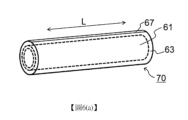
圓筒狀濺鍍靶材1的構成並無特別限定,概略而言,包括:加工成圓筒形狀的濺鍍靶材材料(圓筒部)、與用以安裝於濺鍍裝置上的接合器(adapter)(接頭)。圖2(a)~圖2(d)中示出本發明可利用的圓筒狀濺鍍靶材的構成的示例性變化(均為沿著長度方向L的概略剖面圖)。加工成圓筒形狀的濺鍍靶材材料11只要至少其主體部加工成圓筒形狀即可,亦可對沿著長度方向的剖面上的兩端部的任一者或兩者進行適當加工。更詳細而言,接合器12例如可為凸緣(flange)21(參照圖2(a))、接合環(adapter ring)23(參照圖2(b))、接合器部24(參照圖2(c))、支承管(backing tube)25(參照圖2(d))等形態,並無特別限定。再者,支承管25(圖2(d))可具有圓筒狀的濺鍍靶材支撐部與設置於其端部的接合器部(更詳細而言為凸緣部),該支撐部被插入至加工成圓筒形狀的濺鍍靶材材料11的中空部,該接合器部被用於安裝至濺鍍裝置上。The structure of the
加工成圓筒形狀的濺鍍靶材材料11作為圓筒狀濺鍍靶材1的材料如上所述。接合器12的材料可與加工成圓筒形狀的濺鍍靶材材料11的材料不同,代表性地是可使用強度更高的金屬(一種金屬或者兩種以上的合金)。於接合器12的材料與加工成圓筒形狀的濺鍍靶材材料11的材料不同的情況下,該些材料之間可利用固定部13加以固定(參照圖2(a)、圖2(b)、圖2(d))。固定方法並無特別限定,例如可列舉:鎢-惰性氣體焊接(TIG(Tungsten Inert Gas)焊接)、電子束焊接(EB(Electron Beam)焊接)、金屬惰性氣體焊接(MIG(Metal Inert Gas)焊接)、雷射焊接等焊接、摩擦攪拌接合、焊料接合、硬焊等。或者,接合器12的材料亦可與加工成圓筒形狀的濺鍍靶材材料11的材料相同,例如亦可為對加工成圓筒形狀的濺鍍靶材材料11的至少一端部進行加工而得到的接合器部24的形態(參照圖2(c))。The
圓筒狀濺鍍靶材1除了加工成圓筒形狀的濺鍍靶材材料11及接合器12以外,亦可更包含帽22。更詳細而言,如圖2(a)所示,可將凸緣21作為接合器12固定於加工成圓筒形狀的濺鍍靶材材料11的一端部,並將帽22固定於另一端部。凸緣21及帽22的固定方法並無特別限定,可應用如上所述的任意適當的固定方法。The
於圓筒狀濺鍍靶材1具有凸緣21(或凸緣部)的情況下,能夠於將圓筒狀濺鍍靶材1橫置的狀態下,更加容易地將該捆包體拆包。凸緣21(或凸緣部)具有自其根部的筒狀部向外側伸出的凸部(鍔部),藉由該凸部,而於圓筒狀濺鍍靶材1與片狀緩衝材3(圖2(a)~圖2(d)中未示出)之間形成空間。於對片狀緩衝材3的兩端部進行固定時,若於存在該空間的區域預先設置片狀緩衝材3的兩端部未被固定的部分(於本說明書中,將片狀緩衝材3的兩端部被固定的部分以及未被固定的部分亦分別稱為固定部以及非固定部),則操作者能夠自非固定部插入手指並解除固定部的固定(換言之,將片狀緩衝材3拆封),藉此,能夠更加容易地將圓筒狀濺鍍靶材1的捆包體拆包。When the
根據本實施形態的圓筒狀濺鍍靶材的捆包體10,首先,圓筒狀濺鍍靶材1由至少兩層片狀緩衝材3覆蓋,因此能夠獲得足以保護圓筒狀濺鍍靶材1的耐衝擊性(或緩衝性)。而且,根據本實施形態的圓筒狀濺鍍靶材的捆包體10,於包含圓周方向的剖面上,片狀緩衝材3的兩端部對接,因此,於拆包時,僅解除片狀緩衝材3的固定,更詳細而言,於本實施形態中僅將膠帶5剝離,便能夠將圓筒狀濺鍍靶材1自片狀緩衝材3中立即取出。於長條的(或更大的)圓筒狀濺鍍靶材的情況下,亦能夠容易地實施該拆包,並且不擔心對圓筒狀濺鍍靶材的作為濺鍍面的圓筒部表面造成損傷。另外,由於能夠不切斷片狀緩衝材3地實施該拆包,因此不會產生源自片狀緩衝材3的灰塵,例如於無塵室內拆包的情況下,亦不會產生使無塵室內的清潔度降低的問題。According to the
以上,對本發明的一個實施形態進行了說明,但本實施形態能夠進行各種變更。作為該變更例,以下對本發明的其他實施形態進行說明,但只要無特別說明,則可適用與本實施形態同樣的說明。As mentioned above, one embodiment of the present invention has been described, but various modifications can be made to this embodiment. As this modified example, other embodiments of the present invention will be described below, but unless otherwise specified, the same description as that of this embodiment is applicable.
(實施形態2)
本實施形態是有關於另外一種形態,其為利用片狀緩衝材3將圓筒狀濺鍍靶材1捆包而成的捆包體及其製造方法,圓筒狀濺鍍靶材1的圓筒部由至少兩層片狀緩衝材3覆蓋,於圓筒狀濺鍍靶材1的圓筒部的包含圓周方向的剖面上,片狀緩衝材3的兩端部對接。(Embodiment 2)
This embodiment relates to another form, which is a package body in which the
更詳細而言,如圖3所示,片狀緩衝材3藉由折疊而形成至少兩層。此時,片狀緩衝材3以折疊而形成的各層的大小變得大致均等、較佳為均等的方式折疊(例如,於兩層的情況下,片狀緩衝材3於未折疊而展開的狀態下具有圓筒狀濺鍍靶材1的圓周的大致2倍、較佳為2倍的寬度方向尺寸,且於寬度方向的大致中央部、較佳為中央部折疊)。即,於圖示的形態中,片狀緩衝材3於折疊部F折疊,藉此形成內側層3a及外側層3b這兩層,於包含圓周方向的剖面上,內側層3a具有兩端部A1、A2,外側層3b具有兩端部B1、B2,內側層3a的端部A2及外側層3b的端部B2形成折疊部F(端部A2、B2側的端面)。而且,重疊兩層的片狀緩衝材3的一端部A1、B1與另一端部A2、B2(即,折疊部F)對接。然而,本發明不限定於圖示的形態,片狀緩衝材3可進一步折疊而形成三層以上的層,且片狀緩衝材3於折疊成三層以上的狀態下,包含圓周方向的剖面上的兩端部對接。或者,可將藉由折疊而形成的至少兩層與個別地分離的至少一層組合使用作為片狀緩衝材3,且片狀緩衝材3於折疊的狀態以及個別地分離的狀態下,包含圓周方向的剖面上的兩端部對接。More specifically, as shown in FIG. 3 , the sheet-
如實施形態1中所述般,所謂片狀緩衝材的兩端部「對接」,是指兩端部的端面彼此抵接或接近,例如可應用實施形態1中所述的固定方法來實現。於圖3中,片狀緩衝材3的一端部A1、B1的端面與另一端部A2、B2的端面(折疊部F)抵接,但只要能夠充分保護圓筒狀靶材,則亦可於片狀緩衝材3的兩端部的端面間設置間隙而使其相互接近。此外,與實施形態1同樣的說明亦適用於本實施形態。As described in
根據本實施形態,除了實施形態1中所述的效果以外,亦能夠發揮如下效果:由於將至少一片片狀緩衝材3折疊至少一次來使用,因此能夠無需在意片狀緩衝材3的各層的尺寸對應或捆包時的位置偏移地進行捆包。另外,與將多片個別地分離的片材重疊而使用的情況相比,能夠減少片材彼此相互摩擦的頻率,因此能夠抑制靜電的產生,亦能夠降低捆包時捲入塵埃或灰塵的風險。According to this embodiment, in addition to the effects described in
(實施形態3)
本實施形態是有關於一種如下形態,其為利用片狀緩衝材3將圓筒狀濺鍍靶材1捆包而成的捆包體及其製造方法,圓筒狀濺鍍靶材1的圓筒部由至少兩層片狀緩衝材3覆蓋,於圓筒狀濺鍍靶材1的圓筒部的包含圓周方向的剖面上,片狀緩衝材3的兩端部以該圓筒部的圓周的一半以下的長度重合。(Embodiment 3)
This embodiment relates to a package body in which a
更詳細而言,如圖4所示,片狀緩衝材3藉由折疊而形成至少兩層。即,於圖示的形態中,片狀緩衝材3於折疊部F折疊,藉此形成內側層3a及外側層3b這兩層,於包含圓周方向的剖面上,內側層3a具有兩端部A1、A2,外側層3b具有兩端部B1、B2,內側層3a的端部A2及外側層3b的端部B2形成折疊部F。而且,片狀緩衝材3的一端部A1、B1與另一端部A2、B2的包含圓周方向的剖面上的各重疊長度設為圓筒狀濺鍍靶材1的圓筒部的圓周的一半以下的長度。於各層的重疊長度不同的情況下,例如於圖示的形態中,於內側層3a的端部A1與端部A2的重疊長度dA
與外側層3b的端部B1與端部B2的重疊長度dB
不同的情況下,全部重疊長度設為圓筒狀濺鍍靶材1的圓筒部的圓周的一半以下的長度。然而,本發明不限定於圖示的形態,片狀緩衝材3可進一步折疊而形成三層以上的層,且片狀緩衝材3於折疊成三層以上的狀態下,包含圓周方向的剖面上的兩端部的各重疊長度設為圓筒狀濺鍍靶材1的圓筒部的圓周的一半以下的長度。More specifically, as shown in FIG. 4 , the sheet-
進而,於本實施形態中,如圖4所示,片狀緩衝材3的兩端部藉由該些中的一端部(折疊狀態的片狀緩衝材3的一端部,更詳細而言,位於端部A1、B1側的端部)的外側面、與另一端部(折疊狀態的片狀緩衝材3的另一端部,更詳細而言,位於形成折疊部F的端部A2、B2側的端部)的內側面接觸而重合。Furthermore, in this embodiment, as shown in FIG. 4 , both ends of the sheet-
例如,片狀緩衝材3中位於最外側的層的一端部的外側面(於圖示的形態中為外側層3b的端部B1的外側面)與位於最內側的層的另一端部的內側面(於圖示的形態中為內側層3a的端部A2的內側面)能夠接觸。然而,本發明並不限定於此,只要片狀緩衝材3中某層的外側面與跟其相同或不同的層的內側面接觸,則可以任意組合進行接觸。例如,藉由將片狀緩衝材3的折疊部F插入至相反側的端部之間,首先將內側層與折疊部固定,繼而以自上方覆蓋固定部的方式配置並將外側層固定,能夠防止片狀緩衝材3的鬆弛。For example, the outer surface of one end of the outermost layer of the sheet-like buffer material 3 (in the form shown in the figure, the outer surface of the end B1 of the
本發明中,所謂圓筒狀濺鍍靶材的圓筒部的圓周,是指該圓筒部的外周(以下的實施形態亦同樣)。於本實施形態中,所述重疊長度只要為圓筒狀濺鍍靶材的圓筒部的圓周的一半以下即可,例如為1/3以下,較佳為1/4以下,更佳為1/8以下。藉由將所述重疊的長度設為此種範圍,能夠於橫置的狀態下容易地拆包。In the present invention, the circumference of the cylindrical portion of the cylindrical sputtering target refers to the outer circumference of the cylindrical portion (the same applies to the following embodiments). In this embodiment, the overlapping length only needs to be less than half of the circumference of the cylindrical portion of the cylindrical sputtering target, for example, 1/3 or less, preferably 1/4 or less, and more preferably 1 /8 or less. By setting the overlapping length to such a range, it is possible to easily unpack the package in the horizontal position.
根據本實施形態,除了實施形態1中所述的效果以外,亦能夠發揮容易形成由片狀緩衝材3帶來的隆起部的效果。According to this embodiment, in addition to the effects described in
(實施形態4)
本實施形態是有關於另外一種形態,其為利用片狀緩衝材3將圓筒狀濺鍍靶材1捆包而成的捆包體及其製造方法,圓筒狀濺鍍靶材1的圓筒部由至少兩層片狀緩衝材3覆蓋,於圓筒狀濺鍍靶材1的圓筒部的包含圓周方向的剖面上,片狀緩衝材3的兩端部以該圓筒部的圓周的一半以下的長度重合。(Embodiment 4)
This embodiment relates to another form, which is a package body in which the
更詳細而言,如圖5所示,片狀緩衝材3藉由折疊而形成至少兩層。即,於圖示的形態中,片狀緩衝材3於折疊部F折疊,藉此形成內側層3a及外側層3b這兩層,於包含圓周方向的剖面上,內側層3a具有兩端部A1、A2,外側層3b具有兩端部B1、B2,內側層3a的端部A2及外側層3b的端部B2形成折疊部F。而且,片狀緩衝材3的一端部A1、B1與另一端部A2、B2的包含圓周方向的剖面上的各重疊長度設為圓筒狀濺鍍靶材1的圓筒部的圓周的一半以下的長度。於各層的重疊長度不同的情況下,例如於圖示的形態中,於內側層3a的端部A1與端部A2的重疊長度dA
與外側層3b的端部B1與端部B2的重疊長度dB
不同的情況下,全部重疊長度設為圓筒狀濺鍍靶材1的圓筒部的圓周的一半以下的長度。然而,本發明不限定於圖示的形態,片狀緩衝材3可進一步折疊而形成三層以上的層,且片狀緩衝材3於折疊成三層以上的狀態下,包含圓周方向的剖面上的兩端部的各重疊長度設為圓筒狀濺鍍靶材1的圓筒部的圓周的一半以下的長度。More specifically, as shown in FIG. 5 , the sheet-
進而,於本實施形態中,如圖5所示,片狀緩衝材3的兩端部藉由該些中的一端部(折疊狀態的片狀緩衝材3的一端部,更詳細而言,端部A1、B1側的端部)的內側面、與另一端部(折疊狀態的片狀緩衝材3的另一端部,更詳細而言,形成折疊部F的端部A2、B2側的端部)的內側面接觸而重合。Furthermore, in this embodiment, as shown in FIG. 5 , both ends of the sheet-
例如,片狀緩衝材3中位於最內側的層的一端部的內側面(於圖示的形態中為內側層3a的端部A1的內側面)與位於最內側的層的另一端部的內側面(於圖示的形態中為內側層3a的端部A2的內側面)能夠接觸。For example, the inner surface of one end of the innermost layer of the sheet-like buffer material 3 (in the form shown in the figure, the inner surface of the end A1 of the
於本實施形態中,所述重疊長度只要為圓筒狀濺鍍靶材的圓筒部的圓周的一半以下即可,例如為1/3以下,較佳為1/4以下,更佳為1/8以下。藉由將所述重疊的長度設為此種範圍,不僅能夠於橫置的狀態下容易地拆包,而且能夠無多餘空間地將已捆包的圓筒狀靶材裝箱。In this embodiment, the overlapping length only needs to be less than half of the circumference of the cylindrical portion of the cylindrical sputtering target, for example, 1/3 or less, preferably 1/4 or less, and more preferably 1 /8 or less. By setting the overlapping length within such a range, not only can the package be easily unpacked in a horizontal position, but also the packaged cylindrical target materials can be packed into boxes without extra space.
根據本實施形態,除了實施形態1中所述的效果以外,亦能夠發揮容易形成由片狀緩衝材3帶來的隆起部的效果。另外,由於能夠使用夾子(clip)或封袋器(bag closure)等緊固件而非利用膠帶等黏著劑的固定方法,因此除了能夠更容易地拆包以外,亦無黏著劑的附著,故片狀緩衝材3的再利用亦變得容易。According to this embodiment, in addition to the effects described in
(其他實施形態)
與實施形態2相對於實施形態1的變更相同,對於實施形態3及實施形態4而言,亦可使用個別地分離的至少兩層、或者將藉由折疊而形成的至少兩層與個別地分離的至少一層組合使用作為片狀緩衝材3來進行變更。特別是若使用個別地分離的兩層以上的片狀緩衝材3捆包圓筒狀濺鍍靶材,則能夠於去除被塵埃或灰塵等污染的風險高的最外側的一層之後搬送至無塵室內,能夠防止無塵室的污染。另外,為了進一步防止塵埃或灰塵對無塵室的污染,片狀緩衝材3亦可具有防靜電功能。(Other implementation forms)
Similar to the changes in Embodiment 2 with respect to
另外,於本發明的實施形態中,為了防止圓筒狀濺鍍靶材被塵埃或灰塵等污染,亦可使圓筒狀濺鍍靶材與片狀緩衝材之間存在保護膜。藉此,亦能夠進一步防止於圓筒狀濺鍍靶材的表面、特別是濺鍍面或安裝於濺鍍裝置的面(密封面)上產生由與片狀緩衝材3的摩擦導致的損傷。保護膜只要為能夠保護圓筒狀濺鍍靶材的表面且能夠剝離的膜,則無特別限定。作為保護膜,例如可列舉:聚對苯二甲酸乙二酯、聚對苯二甲酸丁二酯、聚萘二甲酸乙二酯等聚酯系樹脂膜;聚乙烯、聚丙烯膜等聚烯烴系樹脂膜、丙烯酸系樹脂膜等,較佳為選自由聚烯烴系樹脂膜、聚對苯二甲酸乙二酯系樹脂膜及丙烯酸系樹脂膜所組成的群組。In addition, in the embodiment of the present invention, in order to prevent the cylindrical sputtering target from being contaminated by dust or dust, a protective film may be provided between the cylindrical sputtering target and the sheet-shaped buffer material. This can further prevent the surface of the cylindrical sputtering target, particularly the sputtering surface or the surface (sealing surface) mounted on the sputtering device, from being damaged by friction with the sheet-shaped
保護膜的長度可根據圓筒狀濺鍍靶材的長度適當選擇,但就防止圓筒狀濺鍍靶材損傷的觀點而言,較佳為與上文所示的片狀緩衝材3相同。保護膜的寬度可根據圓筒狀濺鍍靶材的外周的直徑適當選擇,較佳為保護膜彼此的重疊長度是成為圓筒狀濺鍍靶材的圓筒部的圓周的一半以下的長度,更佳為以成為1/3以下的方式設定,進而佳為以成為1/4以下的方式設定,特佳為以成為1/8以下的方式設定。另外,亦可貼合多個保護膜,並覆蓋圓筒狀濺鍍靶材的整周,例如於使用兩片保護膜的情況下,以各覆蓋圓筒部的圓周的半周的方式配置保護膜。於使用多個保護膜的情況下,保護膜彼此的重疊長度較佳為成為圓筒狀濺鍍靶材的圓筒部的圓周的一半以下的長度,更佳為以成為1/3以下的方式設定,進而佳為以成為1/4以下的方式設定,特佳為以成為1/8以下的方式設定。The length of the protective film can be appropriately selected according to the length of the cylindrical sputtering target, but from the viewpoint of preventing damage to the cylindrical sputtering target, it is preferably the same as the sheet-shaped
於利用保護膜保護圓筒狀濺鍍靶材的情況下,就拆包容易性的觀點而言,保護膜的兩端、或者一端部與保護膜外周面的固定位置較佳為接近片狀緩衝材3的固定部的位置,各固定部間的距離為圓筒狀濺鍍靶材的圓筒部的圓周的1/3以下,較佳為1/4以下,更佳為1/8以下,進而佳為大致相同位置,特佳為處於相同位置。When a protective film is used to protect the cylindrical sputtering target, from the viewpoint of ease of unpacking, the fixed position of both ends of the protective film or one end and the outer peripheral surface of the protective film is preferably close to the sheet-like buffer The position of the fixed parts of the
進而,於本發明的實施形態中,於要求抑制長期保管時的圓筒狀濺鍍靶材的變質(例如氧化)的情況下,亦可於利用片狀緩衝材捆包之前,對圓筒狀濺鍍靶材進行真空包裝。另外,就防止真空包裝時的損傷的觀點而言,亦可利用包裝材對由所述保護膜保護的圓筒狀濺鍍靶材進行真空包裝。用於真空包裝的包裝材較佳為具有包裝材難以透過氧及水的特性。藉此,能夠抑制圓筒狀濺鍍靶材表面的氧化等變質。所謂難以透過氧及水的特性,是指氧透過率為100 cc/m2 ·atm·day以下、較佳為80 cc/m2 ·atm·day以下、更佳為70 cc/m2 ·atm·day以下,透濕率為20 g/m2 ·day以下、較佳為15 g/m2 ·day以下、更佳為10 g/m2 ·day以下的特性。氧透過率及透濕率是指藉由依照日本工業標準(Japanese Industrial Standards,JIS)K 7126及JIS K 7129的測定方法測定的值。Furthermore, in the embodiment of the present invention, when it is required to suppress deterioration (for example, oxidation) of the cylindrical sputtering target during long-term storage, the cylindrical sputtering target may be packed before being packed with a sheet-like buffer material. The sputtering targets are vacuum packed. In addition, from the viewpoint of preventing damage during vacuum packaging, the cylindrical sputtering target protected by the protective film may be vacuum-packed using a packaging material. It is preferable that the packaging material used for vacuum packaging has the characteristics that oxygen and water are difficult to penetrate through the packaging material. Thereby, it is possible to suppress deterioration such as oxidation on the surface of the cylindrical sputtering target. The characteristic of being difficult to transmit oxygen and water means that the oxygen permeability is 100 cc/m 2 ·atm·day or less, preferably 80 cc/m 2 ·atm·day or less, and more preferably 70 cc/m 2 ·atm ·day or less, and the moisture permeability is 20 g/m 2 ·day or less, preferably 15 g/m 2 ·day or less, more preferably 10 g/m 2 ·day or less. Oxygen transmittance and moisture transmittance refer to values measured by measuring methods in accordance with Japanese Industrial Standards (JIS) K 7126 and JIS K 7129.
例如,作為用於真空包裝的包裝材的具體材料,可列舉樹脂製膜。作為樹脂,例如可列舉:聚丙烯、聚乙烯、奈米複合系塗佈聚對苯二甲酸乙二酯、蒸鍍有鋁的聚對苯二甲酸乙二酯(polyethylene terephthalate,PET)或未拉伸聚丙烯(流延聚丙烯(casting polypropylene,CPP))、蒸鍍有二氧化矽或氧化鋁的PET或雙軸拉伸尼龍(biaxial oriented nylon,ONY)、聚偏二氯乙烯(polyvinylidene chloride,PVDC)、尼龍、PVDC塗佈雙軸拉伸尼龍(PVDC coated biaxial oriented nylon,KON)或雙軸拉伸聚丙烯(PVDC coated biaxial oriented polypropylene,KOP)、PET、聚氯乙烯(polyvinyl chloride,PVC)、雙軸拉伸聚丙烯(biaxial oriented polypropylene,OPP)、高密度聚乙烯(high density polyethylene,HDPE)、低密度聚乙烯(low density polyethylene,LDPE)、乙烯-乙烯醇共聚樹脂(ethylene vinyl alcohol copolymer,EVOH)等,但不限定於該些。另外,亦可為該些樹脂的積層膜、共擠出多層膜等。用於真空包裝的包裝材較佳為積層膜或多層膜。藉由設為該膜層的形態,容易兼具防濕性、耐氧透過性、耐熱性、熱封性、機械強度或柔軟性等多種功能。 [實施例]For example, a specific material for a packaging material used for vacuum packaging includes a resin film. Examples of the resin include polypropylene, polyethylene, nanocomposite-coated polyethylene terephthalate, aluminum-deposited polyethylene terephthalate (PET), or undrawn polyethylene terephthalate. Stretched polypropylene (casting polypropylene (CPP)), PET evaporated with silica or alumina, or biaxially oriented nylon (ONY), polyvinylidene chloride, PVDC), nylon, PVDC coated biaxial oriented nylon (KON) or biaxially oriented polypropylene (PVDC coated biaxial oriented polypropylene, KOP), PET, polyvinyl chloride (PVC) , biaxially oriented polypropylene (OPP), high density polyethylene (HDPE), low density polyethylene (LDPE), ethylene vinyl alcohol copolymer , EVOH), etc., but are not limited to these. In addition, a laminated film of these resins, a co-extruded multilayer film, etc. may also be used. The packaging material used for vacuum packaging is preferably a laminated film or a multi-layer film. By adopting the form of this film layer, it is easy to combine multiple functions such as moisture resistance, oxygen permeation resistance, heat resistance, heat sealability, mechanical strength, and flexibility. [Example]
(實施例1)
實施例1是有關於一種於實施形態2中參照圖3而於上文敘述的圓筒狀濺鍍靶材的捆包體及其製造方法。
準備如下圓筒狀濺鍍靶材(全長2950 mm),其具有長度2750 mm、外徑165 mm、內徑126 mm、且包含高純度(99.999%)鋁的圓筒部,於圓筒部的長度方向兩端部分別具有鋁合金製的凸緣部(端部的直徑為175 mm)及帽部。其質量為73 kg。
利用保護膜(「三井遮蔽膠帶(masking tape)」(註冊商標)、三井化學東賽璐(Mitsui Chemicals Tohcello)股份有限公司製造)保護圓筒狀濺鍍靶材的圓筒部表面。
作為片狀緩衝材,將長度3700 mm、寬度1100 mm的聚乙烯製的氣泡緩衝材「氣帽」(註冊商標)C-800(酒井化學工業股份有限公司製造)於寬度方向中央部折疊而成為兩層。於折疊成兩層的狀態的片狀緩衝材的上側層(對應於內側層)上,將上文中保護了圓筒部表面的圓筒狀濺鍍靶材以他們的長度方向一致進行配置。然後,使折疊而成為兩層的片狀緩衝材沿著圓筒狀濺鍍靶材的圓筒部表面,以於包含圓周方向的剖面上片狀緩衝材的兩端部對接的方式配置,將所述兩端部相對於圓筒狀濺鍍靶材的長度方向以500 mm間隔使用膠帶加以固定。以藉由膠帶而被固定的部分的長度的合計相對於未固定部分的長度(圓筒狀靶材的長度方向的長度)的合計成為4%的方式進行固定(參照圖1(a))。另外,保護膜的固定部與片狀緩衝材的固定部以相對於圓周方向而成為大致相同位置的方式配置。
藉此,得到了利用片狀緩衝材將圓筒狀濺鍍靶材捆包而成的捆包體。(Example 1)
(比較例1) 比較例1是有關於一種參照圖6(a)及圖6(b)而於上文敘述的現有的圓筒狀濺鍍靶材的捆包體及其製造方法。 與實施例1同樣地準備如下圓筒狀濺鍍靶材(全長2950 mm),其具有長度2750 mm、外徑165 mm、內徑126 mm、且包含高純度(99.999%)鋁的圓筒部,於圓筒部的長度方向兩端部分別具有鋁合金製的凸緣部及帽部。 與實施例1同樣地利用保護膜(「三井遮蔽膠帶」(註冊商標)、三井化學東賽璐(Mitsui Chemicals Tohcello)股份有限公司製造)保護圓筒狀濺鍍靶材的圓筒部表面。 作為片狀緩衝材,於長度3700 mm、寬度1100 mm的聚乙烯製的氣泡緩衝材「氣帽」(註冊商標)C-800(酒井化學工業股份有限公司製造)的寬度方向的一端部上,將上文中保護了圓筒部表面的圓筒狀濺鍍靶材以他們的長度方向一致進行配置。然後,一面抬起圓筒狀濺鍍靶材,一面使片狀緩衝材沿著圓筒狀濺鍍靶材的圓筒部表面纏繞兩周來配置,利用膠帶將捲繞結束端部沿著長度方向固定(參照圖6(a)及圖6(b))。 藉此,得到了利用片狀緩衝材將圓筒狀濺鍍靶材捆包而成的捆包體。(Comparative example 1) Comparative Example 1 relates to the conventional cylindrical sputtering target package and its manufacturing method described above with reference to FIGS. 6(a) and 6(b) . The following cylindrical sputtering target (total length 2950 mm) was prepared in the same manner as in Example 1, which had a length of 2750 mm, an outer diameter of 165 mm, an inner diameter of 126 mm, and a cylindrical portion containing high-purity (99.999%) aluminum. , having an aluminum alloy flange part and a cap part respectively at both ends in the length direction of the cylindrical part. In the same manner as in Example 1, the cylindrical surface of the cylindrical sputtering target was protected with a protective film ("Mitsui Masking Tape" (registered trademark), manufactured by Mitsui Chemicals Tohcello Co., Ltd.). As a sheet-like cushioning material, on one end in the width direction of a polyethylene bubble cushioning material "Air Cap" (registered trademark) C-800 (manufactured by Sakai Chemical Industry Co., Ltd.) with a length of 3700 mm and a width of 1100 mm, The cylindrical sputtering targets having the surface of the cylindrical part protected above are arranged so that their length directions are consistent. Then, while lifting the cylindrical sputtering target, the sheet-shaped buffer material is wound twice along the surface of the cylindrical portion of the cylindrical sputtering target, and the winding end end is stretched along the length with tape. The direction is fixed (refer to Figure 6(a) and Figure 6(b)). Thereby, a package body in which the cylindrical sputtering target material was packed with a sheet-shaped buffer material was obtained.
實施例1的捆包體(例如於箱內配置於U字型的底座或U字型的緩衝材上的狀態下)僅將膠帶剝離,而不會使圓筒狀濺鍍靶材沿圓周方向旋轉,另外不會切斷片狀緩衝材,能夠將圓筒狀濺鍍靶材自片狀緩衝材中立即取出並拆包。於長條且質量大的圓筒狀濺鍍靶材的情況下,亦能夠容易地實施該拆包,並且不擔心對圓筒狀濺鍍靶材的作為濺鍍面的圓筒部表面造成損傷。另外,由於能夠不切斷片狀緩衝材地實施該拆包,因此亦不擔心源自片狀緩衝材的灰塵產生並飄舞而污染無塵室。進而,操作者自非固定部(例如膠帶的旁側)沿著片狀緩衝材的兩端部之間插入手指,將固定部的膠帶剝離,藉此能夠容易地實施該拆包。 關於比較例1的捆包體,為了對其進行拆包,需要將膠帶剝離並使圓筒狀濺鍍靶材沿圓周方向旋轉、或者切斷片狀緩衝材。 [產業上之可利用性]The package body of Example 1 (for example, when placed on a U-shaped base or a U-shaped buffer material in a box) only peels off the tape without moving the cylindrical sputtering target in the circumferential direction. By rotating, the cylindrical sputtering target can be immediately taken out and unpacked from the sheet-like buffer material without cutting the sheet-like buffer material. Even in the case of a long and heavy cylindrical sputtering target, this unpacking can be easily performed without worrying about damage to the surface of the cylindrical portion that is the sputtering surface of the cylindrical sputtering target. . In addition, since the unpacking can be performed without cutting the sheet-like buffer material, there is no concern that dust originating from the sheet-like buffer material is generated and blown around to contaminate the clean room. Furthermore, the operator can easily perform unpacking by inserting his fingers from the non-fixed portion (for example, the side of the tape) between both ends of the sheet-like buffering material and peeling off the tape at the fixed portion. In order to unpack the package of Comparative Example 1, it is necessary to peel off the tape and rotate the cylindrical sputtering target in the circumferential direction, or to cut the sheet-like buffer material. [Industrial availability]
藉由本發明而得到的圓筒狀濺鍍靶材的捆包體能夠於將圓筒狀濺鍍靶材橫置的狀態下容易地拆包,進而亦不擔心污染無塵室,能夠用於保護圓筒狀濺鍍靶材免受搬運、保管時可能施加的衝擊等。The package of cylindrical sputtering targets obtained by the present invention can be easily unpacked with the cylindrical sputtering targets placed horizontally, and can be used for protection without fear of contamination of the clean room. The cylindrical sputtering target is protected from possible impacts during transportation and storage.
1:圓筒狀濺鍍靶材
3:片狀緩衝材
3a、3b:層
5:膠帶
10:捆包體
11:加工成圓筒形狀的濺鍍靶材材料
12:接合器
13:固定部
21:凸緣
22:帽
23:接合環
24:接合器部
25:支承管
61:圓筒狀濺鍍靶材
63:片狀緩衝材
67:膠帶
70:現有的圓筒狀濺鍍靶材的捆包體
A1、A2、B1、B2:(包含圓周方向的剖面的)端部
C:切斷部
dA、dB:重疊長度
E:外側端部
F:折疊部
L:長度方向
R:圓周方向1: Cylindrical sputtering target 3: Sheet-shaped
圖1(a)及圖1(b)是表示本發明的一個實施形態的圓筒狀濺鍍靶材的捆包體的概略圖,圖1(a)是立體圖,圖1(b)是與長度方向L垂直的剖面圖(包含圓周方向的剖面的圖)。 圖2(a)~圖2(d)是表示本發明可利用的圓筒狀濺鍍靶材的構成的示例性變化(variation)的、沿著長度方向L的概略剖面圖。 圖3是表示本發明的另一個實施形態的圓筒狀濺鍍靶材的捆包體的概略圖,且是與圖1(b)對應的剖面圖。 圖4是表示本發明的另一個實施形態的圓筒狀濺鍍靶材的捆包體的概略圖,且是與圖1(b)對應的剖面圖。 圖5是表示本發明的另一個實施形態的圓筒狀濺鍍靶材的捆包體的概略圖,且是與圖1(b)對應的剖面圖。 圖6(a)及圖6(b)是表示現有的圓筒狀濺鍍靶材的捆包體的概略圖,圖6(a)是立體圖,圖6(b)是與長度方向L垂直的剖面圖。1(a) and 1(b) are schematic diagrams showing a package body of a cylindrical sputtering target material according to one embodiment of the present invention, with FIG. 1(a) being a perspective view and FIG. 1(b) being A cross-sectional view perpendicular to the length direction L (a view including a cross-section in the circumferential direction). 2(a) to 2(d) are schematic cross-sectional views along the longitudinal direction L showing exemplary variations of the structure of the cylindrical sputtering target that can be used in the present invention. FIG. 3 is a schematic view showing a package of cylindrical sputtering target materials according to another embodiment of the present invention, and is a cross-sectional view corresponding to FIG. 1( b ). FIG. 4 is a schematic view showing a package of cylindrical sputtering target materials according to another embodiment of the present invention, and is a cross-sectional view corresponding to FIG. 1( b ). FIG. 5 is a schematic view showing a package of cylindrical sputtering target materials according to another embodiment of the present invention, and is a cross-sectional view corresponding to FIG. 1( b ). 6(a) and 6(b) are schematic views showing a conventional package of cylindrical sputtering targets. FIG. 6(a) is a perspective view, and FIG. 6(b) is perpendicular to the longitudinal direction L. Sectional view.
1:圓筒狀濺鍍靶材 1: Cylindrical sputtering target
3:片狀緩衝材 3: Sheet buffer material
3a、3b:層 3a, 3b: layer
5:膠帶 5: tape
10:捆包體 10:Bale body
A1、A2、B1、B2:(包含圓周方向的剖面的)端部 A1, A2, B1, B2: Ends (including the circumferential section)
L:長度方向 L:Length direction
R:圓周方向 R: circumferential direction
Claims (16)
Applications Claiming Priority (2)
| Application Number | Priority Date | Filing Date | Title |
|---|---|---|---|
| JP2018176846 | 2018-09-21 | ||
| JP2018-176846 | 2018-09-21 |
Publications (2)
| Publication Number | Publication Date |
|---|---|
| TW202014544A TW202014544A (en) | 2020-04-16 |
| TWI830779B true TWI830779B (en) | 2024-02-01 |
Family
ID=69887450
Family Applications (1)
| Application Number | Title | Priority Date | Filing Date |
|---|---|---|---|
| TW108133650A TWI830779B (en) | 2018-09-21 | 2019-09-18 | Manufacturing method and package of cylindrical sputtering target material package |
Country Status (4)
| Country | Link |
|---|---|
| JP (1) | JP7612320B2 (en) |
| CN (1) | CN112638791B (en) |
| TW (1) | TWI830779B (en) |
| WO (1) | WO2020059590A1 (en) |
Citations (8)
| Publication number | Priority date | Publication date | Assignee | Title |
|---|---|---|---|---|
| JPS5377775A (en) * | 1976-12-20 | 1978-07-10 | Sekisui Plastics | Method of packaging contracted article |
| JPS5590578U (en) * | 1978-12-19 | 1980-06-23 | ||
| JP2001073004A (en) * | 1999-08-31 | 2001-03-21 | Sumitomo Metal Mining Co Ltd | Casting mold |
| US20030091871A1 (en) * | 2001-10-10 | 2003-05-15 | Semiconductor Energy Laboratory Co., Ltd. | Film, packaging material, container, lens, window, spectacles, recording medium, and deposition apparatus |
| JP2011025930A (en) * | 2009-07-21 | 2011-02-10 | Shunwa:Kk | Packing material with cushioning property and impact resistance |
| JP2012012049A (en) * | 2010-06-30 | 2012-01-19 | Mutsumi Shioura | Banana storing sheet |
| JP2012111994A (en) * | 2010-11-24 | 2012-06-14 | Furukawa Electric Co Ltd:The | Cylindrical target material, its manufacturing method and its sheet coating method |
| JP2015161026A (en) * | 2014-02-28 | 2015-09-07 | 本田技研工業株式会社 | Packaging method for Na-containing sputtering target |
Family Cites Families (15)
| Publication number | Priority date | Publication date | Assignee | Title |
|---|---|---|---|---|
| CH168161A (en) * | 1932-03-03 | 1934-03-31 | A S Rena Kartonfabrik | Collapsible packaging bin made of stiff cardboard. |
| JP2000255664A (en) * | 1999-03-12 | 2000-09-19 | Shin Etsu Chem Co Ltd | Packing of optical fiber preform |
| JP2001213479A (en) * | 2000-02-03 | 2001-08-07 | Daiwa Packs:Kk | Buffer |
| ATE409657T1 (en) * | 2001-06-18 | 2008-10-15 | Dietrich Mueller | CYLINDRICAL SHIPPING TUBE WITH STABILIZING ELEMENT |
| US6794018B2 (en) * | 2002-11-04 | 2004-09-21 | Newark Group Industries, Inc. | Packaging article |
| US7754310B2 (en) * | 2007-07-17 | 2010-07-13 | Sheng-Hsi Kuo | Packaging buffer material |
| JP4523669B1 (en) * | 2009-11-26 | 2010-08-11 | 岡葉流通株式会社 | Protective packaging |
| CN201647363U (en) * | 2009-12-31 | 2010-11-24 | 常州金海塑业有限公司 | Outer package for cylindrical film roll |
| JP2013227073A (en) * | 2012-03-30 | 2013-11-07 | Kuraray Co Ltd | Film roll package |
| JP5813568B2 (en) * | 2012-04-27 | 2015-11-17 | 旭化成ケミカルズ株式会社 | Vinylidene chloride-based resin laminated film and easy-open tubular sealed package using the same |
| CN106233169A (en) * | 2014-04-17 | 2016-12-14 | 柯尼卡美能达株式会社 | Light reflective film volume and light reflective film coil packing body |
| EP3145833B1 (en) * | 2014-05-23 | 2019-10-23 | Essity Hygiene and Health Aktiebolag | A package containing rolls of absorbent material |
| DE102015004918B3 (en) * | 2015-04-17 | 2016-06-30 | Johann Roiser | Packaging for rolls |
| CN106314927B (en) * | 2015-06-30 | 2024-02-06 | 嘉兴山蒲照明电器有限公司 | Packing box of straight tube lamp |
| CN207375013U (en) * | 2017-10-16 | 2018-05-18 | 深圳市盛国风塑胶有限公司 | A kind of enviroment protective packing bag with double-deck gas bag |
-
2019
- 2019-08-30 JP JP2019157746A patent/JP7612320B2/en active Active
- 2019-09-11 CN CN201980056277.7A patent/CN112638791B/en active Active
- 2019-09-11 WO PCT/JP2019/035671 patent/WO2020059590A1/en not_active Ceased
- 2019-09-18 TW TW108133650A patent/TWI830779B/en active
Patent Citations (8)
| Publication number | Priority date | Publication date | Assignee | Title |
|---|---|---|---|---|
| JPS5377775A (en) * | 1976-12-20 | 1978-07-10 | Sekisui Plastics | Method of packaging contracted article |
| JPS5590578U (en) * | 1978-12-19 | 1980-06-23 | ||
| JP2001073004A (en) * | 1999-08-31 | 2001-03-21 | Sumitomo Metal Mining Co Ltd | Casting mold |
| US20030091871A1 (en) * | 2001-10-10 | 2003-05-15 | Semiconductor Energy Laboratory Co., Ltd. | Film, packaging material, container, lens, window, spectacles, recording medium, and deposition apparatus |
| JP2011025930A (en) * | 2009-07-21 | 2011-02-10 | Shunwa:Kk | Packing material with cushioning property and impact resistance |
| JP2012012049A (en) * | 2010-06-30 | 2012-01-19 | Mutsumi Shioura | Banana storing sheet |
| JP2012111994A (en) * | 2010-11-24 | 2012-06-14 | Furukawa Electric Co Ltd:The | Cylindrical target material, its manufacturing method and its sheet coating method |
| JP2015161026A (en) * | 2014-02-28 | 2015-09-07 | 本田技研工業株式会社 | Packaging method for Na-containing sputtering target |
Also Published As
| Publication number | Publication date |
|---|---|
| JP7612320B2 (en) | 2025-01-14 |
| CN112638791B (en) | 2022-08-16 |
| WO2020059590A1 (en) | 2020-03-26 |
| TW202014544A (en) | 2020-04-16 |
| CN112638791A (en) | 2021-04-09 |
| JP2020050950A (en) | 2020-04-02 |
Similar Documents
| Publication | Publication Date | Title |
|---|---|---|
| TWI830779B (en) | Manufacturing method and package of cylindrical sputtering target material package | |
| JP5303963B2 (en) | Package having release film and method for producing the same | |
| JP2004244048A (en) | Clean packaging bag and manufacturing method thereof | |
| JP6069975B2 (en) | Packaging bag and manufacturing method thereof | |
| JP2016196323A (en) | Film roll package of packaging material for battery | |
| WO2002018220A1 (en) | Packaging bag for semiconductor wafer and method of packaging semiconductor wafer using the packaging bag | |
| CN111217024B (en) | Sputtering target packaging structure and sputtering target packaging method | |
| JP5198043B2 (en) | Double bag for clean packaging | |
| JP3788771B2 (en) | Welding wire storage container and container-containing welding wire | |
| JP2006131295A (en) | Packaging body for packaging many duct heat insulating materials and its production method | |
| TWI511872B (en) | Method of packaging for thin fragile parts | |
| JP5950879B2 (en) | Coil packing body and coil body packing method | |
| ES2457065T5 (en) | Metalloplastic multilayer packaging film | |
| JP2000355067A (en) | Clean film for packaging and packaging bag using the same | |
| JP7746680B2 (en) | Packaging laminated film | |
| JP2020084316A (en) | Sputtering target packaging structure | |
| JP2020083477A (en) | Packaging structure for sputtering target | |
| JP3807176B2 (en) | Barrier packaging material and packaging bag using the same | |
| TW201236926A (en) | Protective envelope | |
| JP2020192689A (en) | Laminate for packaging bag and packaging bag using the same, and method for producing the packaging bag | |
| JP2012066837A (en) | Photosensitive adhesive film package | |
| JP2008247417A (en) | Packaging bag | |
| JP3169015U (en) | Paper bag whose innermost layer is a barrier layer | |
| JP2020040677A (en) | Film reel package and film reel collected package | |
| WO2006002806A1 (en) | Laminate |