TWI815149B - screws - Google Patents

screws Download PDF

Info

Publication number
TWI815149B
TWI815149B TW110126804A TW110126804A TWI815149B TW I815149 B TWI815149 B TW I815149B TW 110126804 A TW110126804 A TW 110126804A TW 110126804 A TW110126804 A TW 110126804A TW I815149 B TWI815149 B TW I815149B
Authority
TW
Taiwan
Prior art keywords
screw
shaft
chip
grooves
screw according
Prior art date
Application number
TW110126804A
Other languages
Chinese (zh)
Other versions
TW202305253A (en
Inventor
趙穎慶
Original Assignee
趙穎慶
Priority date (The priority date is an assumption and is not a legal conclusion. Google has not performed a legal analysis and makes no representation as to the accuracy of the date listed.)
Filing date
Publication date
Application filed by 趙穎慶 filed Critical 趙穎慶
Priority to TW110126804A priority Critical patent/TWI815149B/en
Priority to AU2021257937A priority patent/AU2021257937B2/en
Priority to EP22180591.4A priority patent/EP4123188B1/en
Priority to PL22180591.4T priority patent/PL4123188T3/en
Priority to EP25178573.9A priority patent/EP4582705A3/en
Priority to JP2022115359A priority patent/JP7601415B2/en
Publication of TW202305253A publication Critical patent/TW202305253A/en
Application granted granted Critical
Publication of TWI815149B publication Critical patent/TWI815149B/en

Links

Images

Classifications

    • FMECHANICAL ENGINEERING; LIGHTING; HEATING; WEAPONS; BLASTING
    • F16ENGINEERING ELEMENTS AND UNITS; GENERAL MEASURES FOR PRODUCING AND MAINTAINING EFFECTIVE FUNCTIONING OF MACHINES OR INSTALLATIONS; THERMAL INSULATION IN GENERAL
    • F16BDEVICES FOR FASTENING OR SECURING CONSTRUCTIONAL ELEMENTS OR MACHINE PARTS TOGETHER, e.g. NAILS, BOLTS, CIRCLIPS, CLAMPS, CLIPS OR WEDGES; JOINTS OR JOINTING
    • F16B25/00Screws that cut thread in the body into which they are screwed, e.g. wood screws
    • F16B25/0036Screws that cut thread in the body into which they are screwed, e.g. wood screws characterised by geometric details of the screw
    • F16B25/0084Screws that cut thread in the body into which they are screwed, e.g. wood screws characterised by geometric details of the screw characterised by geometric details of the tip
    • FMECHANICAL ENGINEERING; LIGHTING; HEATING; WEAPONS; BLASTING
    • F16ENGINEERING ELEMENTS AND UNITS; GENERAL MEASURES FOR PRODUCING AND MAINTAINING EFFECTIVE FUNCTIONING OF MACHINES OR INSTALLATIONS; THERMAL INSULATION IN GENERAL
    • F16BDEVICES FOR FASTENING OR SECURING CONSTRUCTIONAL ELEMENTS OR MACHINE PARTS TOGETHER, e.g. NAILS, BOLTS, CIRCLIPS, CLAMPS, CLIPS OR WEDGES; JOINTS OR JOINTING
    • F16B25/00Screws that cut thread in the body into which they are screwed, e.g. wood screws
    • F16B25/001Screws that cut thread in the body into which they are screwed, e.g. wood screws characterised by the material of the body into which the screw is screwed
    • F16B25/0015Screws that cut thread in the body into which they are screwed, e.g. wood screws characterised by the material of the body into which the screw is screwed the material being a soft organic material, e.g. wood or plastic
    • FMECHANICAL ENGINEERING; LIGHTING; HEATING; WEAPONS; BLASTING
    • F16ENGINEERING ELEMENTS AND UNITS; GENERAL MEASURES FOR PRODUCING AND MAINTAINING EFFECTIVE FUNCTIONING OF MACHINES OR INSTALLATIONS; THERMAL INSULATION IN GENERAL
    • F16BDEVICES FOR FASTENING OR SECURING CONSTRUCTIONAL ELEMENTS OR MACHINE PARTS TOGETHER, e.g. NAILS, BOLTS, CIRCLIPS, CLAMPS, CLIPS OR WEDGES; JOINTS OR JOINTING
    • F16B25/00Screws that cut thread in the body into which they are screwed, e.g. wood screws
    • F16B25/0036Screws that cut thread in the body into which they are screwed, e.g. wood screws characterised by geometric details of the screw
    • F16B25/0078Screws that cut thread in the body into which they are screwed, e.g. wood screws characterised by geometric details of the screw with a shaft of non-circular cross-section or other special geometric features of the shaft
    • FMECHANICAL ENGINEERING; LIGHTING; HEATING; WEAPONS; BLASTING
    • F16ENGINEERING ELEMENTS AND UNITS; GENERAL MEASURES FOR PRODUCING AND MAINTAINING EFFECTIVE FUNCTIONING OF MACHINES OR INSTALLATIONS; THERMAL INSULATION IN GENERAL
    • F16BDEVICES FOR FASTENING OR SECURING CONSTRUCTIONAL ELEMENTS OR MACHINE PARTS TOGETHER, e.g. NAILS, BOLTS, CIRCLIPS, CLAMPS, CLIPS OR WEDGES; JOINTS OR JOINTING
    • F16B25/00Screws that cut thread in the body into which they are screwed, e.g. wood screws
    • F16B25/10Screws performing an additional function to thread-forming, e.g. drill screws or self-piercing screws
    • F16B25/103Screws performing an additional function to thread-forming, e.g. drill screws or self-piercing screws by means of a drilling screw-point, i.e. with a cutting and material removing action

Landscapes

  • Engineering & Computer Science (AREA)
  • General Engineering & Computer Science (AREA)
  • Mechanical Engineering (AREA)
  • Physics & Mathematics (AREA)
  • Geometry (AREA)
  • Life Sciences & Earth Sciences (AREA)
  • Chemical & Material Sciences (AREA)
  • Dispersion Chemistry (AREA)
  • Wood Science & Technology (AREA)
  • Drilling Tools (AREA)
  • Processing Of Stones Or Stones Resemblance Materials (AREA)
  • Earth Drilling (AREA)
  • Connection Of Plates (AREA)
  • Injection Moulding Of Plastics Or The Like (AREA)
  • Electrical Discharge Machining, Electrochemical Machining, And Combined Machining (AREA)
  • Transmission Devices (AREA)
  • Portable Nailing Machines And Staplers (AREA)
  • Polyesters Or Polycarbonates (AREA)
  • Heterocyclic Compounds That Contain Two Or More Ring Oxygen Atoms (AREA)
  • Glass Compositions (AREA)

Abstract

一種螺絲,包含一螺頭、一自該螺頭沿一軸線延伸的桿身、一螺旋環設於該桿身的螺牙,及多道與該螺牙同向傾斜地形成於該桿身上的排屑溝。其中,該桿身包括一本體,及一連接於該本體之一端的尖尾。每一排屑溝與該軸線間的傾斜角為5~35度,藉由該等排屑溝之參數的優化,可增進該螺絲鑽攻時的排屑能力,同時降低螺入時所需的扭力,進而達成施工時之省時省力的效果。 A screw includes a screw head, a shaft extending from the screw head along an axis, a thread spirally arranged on the shaft, and a plurality of rows formed on the shaft obliquely in the same direction as the thread. Chip trench. Wherein, the shaft includes a body and a pointed tail connected to one end of the body. The inclination angle between each chip groove and the axis is 5 to 35 degrees. By optimizing the parameters of these chip grooves, the chip removal capacity of the screw can be improved while drilling and tapping, while reducing the time required for screw insertion. torque, thus achieving the effect of saving time and effort during construction.

Description

螺絲 screws

本發明是有關於一種鎖固工件,特別是指一種螺絲。 The present invention relates to a locking workpiece, in particular to a screw.

參閱圖1,為一習知的螺絲1,該螺絲1包括一螺頭11、一自該螺頭11向下延伸的桿體12、一螺旋環繞於該桿體12外周緣的外螺牙13,及一設置於該桿體12末端的尖尾14。其中,為減少木質工件因螺入而產生龜裂,該尖尾14具有一沿着一中心線A之截面面積占比四分之一,且呈90度凹設的V形排屑溝15。 Referring to Figure 1, a conventional screw 1 is shown. The screw 1 includes a screw head 11, a rod body 12 extending downward from the screw head 11, and an external thread 13 spirally surrounding the outer periphery of the rod body 12. , and a pointed tail 14 provided at the end of the rod body 12 . Among them, in order to reduce cracks caused by screwing in the wooden workpiece, the tip tail 14 has a V-shaped chip discharge groove 15 that accounts for one-quarter of the cross-sectional area along a center line A and is concave at 90 degrees.

該螺絲1進行鎖合時,是以該尖尾14先行頂壓於木質工件之表面,隨後藉由電動工具經該螺頭11施力,使該螺絲1旋轉而由該尖尾14鑽削螺入木質工件中。然而,該螺絲1進行螺入鑽削之動作時,由於該V形排屑溝15容屑量太小,因而無法隨著鑽削而將木屑順利排出。況且,強大的螺入壓力也會透過該外螺牙13及該桿體12壓迫木質工件,且因而產生擴張應力集中,因此極易令木質工件因受壓過大而產生龜裂,進而損及木質工件的結構強度,並且影響螺固效果。尤其,當木質工件表面一旦出現龜裂現象,即會嚴重 破壞該木質工件之完整性及商品安全性。另外,由於該螺絲1螺入時扭轉力太大,若施工人員是以手動作業,還可能造成施工人員手部的傷害。 When the screw 1 is locked, the pointed tail 14 is first pressed against the surface of the wooden workpiece, and then the power tool is used to apply force through the screw head 11 to rotate the screw 1 and drill the screw through the pointed tail 14 . into wooden workpieces. However, when the screw 1 is being threaded and drilled, the chip holding capacity of the V-shaped chip discharge groove 15 is too small, so the wood chips cannot be smoothly discharged along with the drilling. Moreover, the strong screwing pressure will also compress the wooden workpiece through the external thread 13 and the rod body 12, and thus cause expansion stress concentration. Therefore, it is easy for the wooden workpiece to crack due to excessive pressure, thereby damaging the wood. The structural strength of the workpiece and affects the screwing effect. In particular, once cracks appear on the surface of wooden workpieces, serious damage will occur. Destroy the integrity of the wooden workpiece and the safety of the product. In addition, since the twisting force of the screw 1 is too large when screwed in, if the construction workers work manually, it may also cause injuries to the hands of the construction workers.

因此,該螺絲1的該V形排屑溝15之設計,直接攸關該木質工件的品質以及施工成敗,如何妥善設計排屑構造,在螺入動作過程中能確保木質工件不會產生龜裂,並減輕螺入摩擦扭力,甚至改善排屑的順暢度,已為螺絲製造業者亟待解決的大課題。 Therefore, the design of the V-shaped chip removal groove 15 of the screw 1 is directly related to the quality of the wooden workpiece and the success or failure of the construction. How to properly design the chip removal structure can ensure that the wooden workpiece will not crack during the screwing process. , and reduce the screw friction torque, and even improve the smoothness of chip removal, which has become a major issue that screw manufacturers need to solve urgently.

因此,本發明之目的,即在提供一種能優化螺入及排屑性能,且同時減輕扭力並提升拉拔力的螺絲。 Therefore, the purpose of the present invention is to provide a screw that can optimize the screwing-in and chip-removing performance, while reducing the torque and increasing the pulling force.

於是,本發明螺絲,包含一螺頭、一自該螺頭沿一軸線延伸的桿身、一螺旋環設於該桿身的螺牙,及多道與該螺牙同向傾斜地形成於該桿身上的排屑溝。其中,該桿身包括一本體,及一連接於該本體之一端的尖尾。每一排屑溝與該軸線間的傾斜角為5~35度,且該等排屑溝有至少二道為彼此平行。 Therefore, the screw of the present invention includes a screw head, a shaft extending from the screw head along an axis, a thread spirally ringed on the shaft, and a plurality of threads formed on the shaft obliquely in the same direction as the thread. The debris drain on the body. Wherein, the shaft includes a body and a pointed tail connected to one end of the body. The inclination angle between each chip discharge groove and the axis is 5 to 35 degrees, and at least two of the chip discharge grooves are parallel to each other.

另外,本發明螺絲,包含一螺頭、一自該螺頭沿一軸線延伸的桿身、一螺旋環設於該桿身的螺牙,及二道與該螺牙同向傾斜地形成於該桿身上且彼此不平行的排屑溝。其中,該桿身包括一本體,及一連接於該本體之一端的尖尾。該等排屑溝的任一道與該 軸線間的傾斜角為5~25度。 In addition, the screw of the present invention includes a screw head, a shaft extending along an axis from the screw head, a screw thread spirally ringed on the shaft, and two threads formed on the rod obliquely in the same direction as the screw thread. The flutes are not parallel to each other. Wherein, the shaft includes a body and a pointed tail connected to one end of the body. Any one of the chip removal grooves is connected to the The tilt angle between the axes is 5 to 25 degrees.

本發明之功效在於:藉由該等排屑溝之傾斜角參數的優化,由實際測量之扭力值的明顯降低,證實能配合該桿身之該尖尾及該螺牙的鑽攻,提供優異的排屑性能,藉此增進該螺絲鑽攻時的排屑能力,同時降低螺入時所需的扭力,進而達成施工時之省時省力的效果。 The effect of the present invention is: through the optimization of the inclination angle parameters of the chip removal grooves, and the significant reduction of the actual measured torque value, it is confirmed that it can cooperate with the drilling and tapping of the tip tail of the shaft and the thread to provide excellent The chip removal performance of the screw improves the chip removal ability when drilling and tapping, and at the same time reduces the torque required when screwing in, thus achieving the effect of saving time and effort during construction.

2:螺頭 2: screw head

3:桿身 3: Shaft

31:本體 31:Ontology

32:尖尾 32: pointed tail

321:切削面 321:Cutting surface

4:螺牙 4: thread

5:排屑溝 5: Chip ditch

6:肋條 6:ribs

α:角度 α: angle

Z:軸線 Z: axis

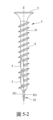
本發明之其它的特徵及功效,將於參照圖式的實施方式中清楚地呈現,其中:圖1是一側視圖,說明一習知的螺絲;圖2是一側視圖,說明本發明螺絲的一第一實施例;圖2-1是圖2的一局部放大示意圖,說明該第一實施例的二道排屑溝;圖3是一局部放大圖,說明本發明螺絲的一第二實施例,及該第二實施例的多個肋條;圖3-1是一類似圖3的局部放大圖,說明該第二實施例之該等排屑溝及多個肋條;圖3-2是一側視圖,說明該等肋條形成於不同位置的實施態樣; 圖4是一類似圖3的局部放大圖,說明該第二實施例的另一實施態樣;圖5是一側視圖,說明本發明螺絲的一第三實施例;圖5-1至圖5-7皆是類似圖5的側視圖,說明該第三實施例的不同實施態樣;圖6是一局部放大圖,說明本發明螺絲的一第四實施例;圖6-1至圖6-7皆是類似圖6的局部放大圖,說明該第四實施例的其它實施態樣;圖7是一側視圖,說明本發明螺絲的一第五實施例;圖7-1至圖7-3皆是類似圖7的側視圖,說明該第五實施例之其它實施態樣;圖8是一側視圖,說明本發明螺絲的一第六實施例;圖8-1、圖8-2、圖8-4、圖8-5皆是類似圖8的側視圖,說明該第六實施例的其他實施態樣;圖8-3是一局部放大圖,說明該第六實施例的另一種實施態樣;圖9是一局部放大圖,說明本發明螺絲的一第七實施例;及圖10-1至圖10-6皆是剖視的示意圖,說明所述排屑溝之截面的不同型態。 Other features and effects of the present invention will be clearly presented in the embodiments with reference to the drawings, wherein: Figure 1 is a side view illustrating a conventional screw; Figure 2 is a side view illustrating the screw of the present invention. A first embodiment; Figure 2-1 is a partially enlarged schematic diagram of Figure 2, illustrating the two chip removal grooves of the first embodiment; Figure 3 is a partially enlarged diagram illustrating a second embodiment of the screw of the present invention , and a plurality of ribs of the second embodiment; Figure 3-1 is a partial enlarged view similar to Figure 3, illustrating the chip removal grooves and a plurality of ribs of the second embodiment; Figure 3-2 is a side view Views illustrating the implementation of the ribs formed at different positions; Figure 4 is a partially enlarged view similar to Figure 3, illustrating another implementation aspect of the second embodiment; Figure 5 is a side view, illustrating a third embodiment of the screw of the present invention; Figures 5-1 to 5 -7 are side views similar to Figure 5, illustrating different implementation aspects of the third embodiment; Figure 6 is a partial enlarged view, illustrating a fourth embodiment of the screw of the present invention; Figures 6-1 to 6- 7 are partial enlarged views similar to Figure 6, illustrating other implementation aspects of the fourth embodiment; Figure 7 is a side view, illustrating a fifth embodiment of the screw of the present invention; Figures 7-1 to 7-3 They are all side views similar to Figure 7, illustrating other implementation aspects of the fifth embodiment; Figure 8 is a side view, illustrating a sixth embodiment of the screw of the present invention; Figure 8-1, Figure 8-2, Figure 8-4 and Figure 8-5 are side views similar to Figure 8, illustrating other implementation aspects of the sixth embodiment; Figure 8-3 is a partially enlarged view, illustrating another implementation aspect of the sixth embodiment. Like this; Figure 9 is a partially enlarged view illustrating a seventh embodiment of the screw of the present invention; and Figures 10-1 to 10-6 are all schematic cross-sectional views illustrating different types of cross-sections of the chip discharge groove. .

在本發明被詳細描述之前,應當注意在以下的說明內容中,類似的元件是以相同的編號來表示。 Before the present invention is described in detail, it should be noted that in the following description, similar elements are designated with the same numbering.

參閱圖2,本發明螺絲之一第一實施例,包含一螺頭2、一自該螺頭2沿一軸線Z延伸的桿身3、一螺旋環設於該桿身3的螺牙4,及二道彼此間隔且與該螺牙4同向傾斜地形成於該桿身3上的排屑溝5。 Referring to Figure 2, a first embodiment of the screw of the present invention includes a screw head 2, a shaft 3 extending from the screw head 2 along an axis Z, and a spiral thread 4 arranged on the shaft 3. And two chip removal grooves 5 are formed on the shaft 3 and are spaced apart from each other and inclined in the same direction as the screw thread 4 .

其中,該桿身3包括一本體31,及一連接於該本體31之一端的尖尾32。所述尖尾32概呈錐狀,能在該桿身3因自該螺頭2所施加之旋轉力而旋轉時,配合該螺牙4產生鑽攻效果。 The shaft 3 includes a body 31 and a tip 32 connected to one end of the body 31 . The pointed tail 32 is generally tapered and can cooperate with the thread 4 to produce a drilling effect when the shaft 3 rotates due to the rotational force exerted from the screw head 2 .

同時參閱圖2與圖2-1,每一排屑溝5與該軸線Z間的傾斜角之角度α為5~35度,而所述排屑溝5之切削深度較佳為該螺牙4之牙外徑的1/2,且該等排屑溝5至少其中之一延伸至該桿身3的該尖尾32。其中,上方的該排屑溝5沿垂直其延伸方向之寬度,較佳為下方的該排屑溝5沿垂直其延伸方向之寬度的0.3~4.5倍,而該等排屑溝5彼此間距為至少0.3mm以上,且沿垂直該軸線Z之方向的投影範圍至少有一部分重疊(如圖2-1所呈現)為較佳的實施方式;再者,該等排屑溝5之間距實際上是以對應其傾斜角度與該桿身3的外徑來做設定。另外,在本第一實施例雖然是以包含二道排屑溝5的型態進行說明,實際實施時仍能設計三個甚至三個以上的排屑溝 5,但以至少有二道排屑溝5彼此平行且位於同一側的型態為較佳的實施方式。 Referring to Figure 2 and Figure 2-1 at the same time, the inclination angle α between each chip groove 5 and the axis Z is 5 to 35 degrees, and the cutting depth of the chip groove 5 is preferably the thread 4 1/2 of the outer diameter of the tooth, and at least one of the chip removal grooves 5 extends to the tip 32 of the shaft 3 . Among them, the width of the upper chip discharge groove 5 along the direction perpendicular to its extension is preferably 0.3 to 4.5 times the width of the lower chip discharge trench 5 along the direction perpendicular to its extension, and the distance between the chip discharge grooves 5 is At least 0.3mm or more, and the projection range along the direction perpendicular to the axis Z overlaps at least partially (as shown in Figure 2-1) is a preferred implementation; furthermore, the distance between the chip discharge grooves 5 is actually The setting is made corresponding to the inclination angle and the outer diameter of the shaft 3 . In addition, although the first embodiment is described as including two chip discharge grooves 5, in actual implementation, three or even more chip discharge grooves can still be designed. 5, but it is a preferred embodiment to have at least two chip removal grooves 5 parallel to each other and located on the same side.

要特別說明的是,所述排屑溝5的切削深度最深處大於該螺牙4之牙外徑的1/2時,雖然可因應更大排屑量的需求,但該桿身3也會因被切削過深而變薄,進而影響整體結構強度,雖然可以在後製程以熱處理方式加強強度,但熱處理後會變得太硬,仍有脆斷的危機;而若靠近該桿身3末端的該排屑溝5的切削深度最深處小於該螺牙4之牙外徑的1/2,雖然可相對增強整體的結構強度,但排屑及容屑的效果也較不理想。另外,若使用相同外徑的刀片加工,當靠近該桿身3末端的該排屑溝5切削深度最深處為1/2牙外徑時,其上方的該排屑溝5會因與下方之該排屑溝5的間距以及傾斜角度而使其切削深度有所差異而無法達到1/2牙外徑。圖2與圖2-1是以相同外徑刀片同時加工為例,而申請應用範圍在不同位置所述排屑溝5,也可以選擇不同的刀片外徑使用,且不以此為限。 It should be noted that when the deepest cutting depth of the chip removal groove 5 is greater than 1/2 of the outer diameter of the screw thread 4, although it can meet the demand for a larger chip removal volume, the shaft 3 will also It becomes thinner due to being cut too deep, which affects the overall structural strength. Although the strength can be strengthened by heat treatment in the post-processing process, it will become too hard after heat treatment and there is still a risk of brittle fracture; and if it is close to the end of the shaft 3 The deepest cutting depth of the chip removal groove 5 is less than 1/2 of the outer diameter of the thread 4. Although the overall structural strength can be relatively enhanced, the chip removal and chip holding effects are also less than ideal. In addition, if inserts with the same outer diameter are used for processing, when the deepest cutting depth of the chip groove 5 near the end of the shaft 3 is 1/2 the outer diameter of the tooth, the chip groove 5 above it will be different from the chip groove 5 below it. The cutting depth varies due to the spacing and inclination angle of the chip grooves 5 and cannot reach 1/2 the outer diameter of the tooth. Figure 2 and Figure 2-1 are examples of simultaneous processing of inserts with the same outer diameter. If the chip removal groove 5 is applied in different positions, different outer diameters of inserts can also be used, and the application is not limited to this.

Figure 110126804-A0305-02-0007-1

由上述表一所呈現之實驗數據可知,藉由本第一實施 例之該等排屑溝5之傾斜角度的優化,能配合該桿身3之該尖尾32及該螺牙4的鑽攻,提供優異的排屑性能,藉此增進本發明螺絲鑽攻時的排屑能力,且又確實可大幅降低螺入時所需的扭力,進而達成施工時之省時省力的效果。值得特別說明的是,配合各種螺絲尺寸的差異,以及因為鎖入的木頭種類不同與應用領域不同,所以也能同時藉由調整該等排屑溝5的寬度,再配合該等排屑溝5的優化角度,來達到降低旋入阻力最佳化的目的。進一步補充說明的是,靠近該桿身3末端之所述排屑溝5的初始寬度設定,會依照該螺牙4之牙外徑與傾斜角度來做設定,以一般牙外徑8mm為例,靠近該桿身3末端的該排屑溝5的寬度會是介於2.5~8.5mm之間而以一定比例存在,會依照需求或是欲鎖入之木頭種類不同挑選適當寬度,若無特定要求,初始寬度為牙外徑的一半,而其上方的該排屑溝5會再依照該靠近該桿身3末端的該排屑溝5的寬度做設定。此外,也由於使用本第一實施例螺鎖時所需施加的扭力較低,應用於木質工件時也因此能降低龜裂的可能性,藉此提升使用本第一實施例時的施工品質。另外,如表一所呈現的數據,可能因木質工件的品種、硬度等等參數而有所改變,但優化的傾斜角度所造成之扭力值趨勢則不會因而受到影響,所呈現之資訊仍可證實本第一實施例所預期的功效。 It can be seen from the experimental data presented in Table 1 above that through this first implementation For example, the optimization of the inclination angle of the chip removal groove 5 can cooperate with the drilling and tapping of the tip 32 of the shaft 3 and the thread 4 to provide excellent chip removal performance, thereby improving the screw drilling and tapping time of the present invention. It has excellent chip removal ability and can indeed significantly reduce the torque required when screwing in, thereby saving time and effort during construction. It is worth mentioning that, in line with the differences in the sizes of various screws, and because the types of wood to be locked are different and the application fields are different, the width of the chip discharge grooves 5 can also be adjusted at the same time to match the chip discharge grooves 5 The optimization angle is to achieve the purpose of reducing the screw-in resistance and optimizing it. It is further added that the initial width setting of the chip removal groove 5 near the end of the shaft 3 will be set according to the outer diameter and inclination angle of the screw thread 4. Taking the general outer diameter of the thread 8mm as an example, The width of the chip removal groove 5 near the end of the shaft 3 will be between 2.5~8.5mm and exist in a certain proportion. The appropriate width will be selected according to the needs or the type of wood to be locked. If there are no specific requirements , the initial width is half of the outer diameter of the tooth, and the chip discharge groove 5 above it will be set according to the width of the chip discharge groove 5 near the end of the shaft 3 . In addition, because the torque required when using the screw lock of the first embodiment is low, the possibility of cracking when applied to wooden workpieces can be reduced, thereby improving the construction quality when using the first embodiment. In addition, the data shown in Table 1 may change due to the type, hardness and other parameters of the wooden workpiece, but the trend of the torque value caused by the optimized tilt angle will not be affected, and the information presented can still be The expected effect of this first embodiment is confirmed.

參閱圖3,為本發明螺絲的一第二實施例,本第二實施 例與該第一實施例的區別在於:本第二實施例還包含多個形成於該螺牙4之部分的相鄰結構之間的肋條6,而該等排屑溝5相對於該尖尾32的位置得以如圖3-1所呈現地對應調整。若進一步在該螺牙4之部分的相鄰結構之間加上多個肋條6,而所述肋條6可相對於該軸線Z傾斜,亦能與該軸線Z平行,能藉此達成優化擴孔效果的目的,且所述擴孔效果還加乘了降低旋入阻力的性能。此外,所述肋條6的延伸方向,可與該等排屑溝5同向或反向,並不以圖3及圖3-1所繪示為限。另外如圖3-2所示,除了如圖3及圖3-1所示地使該等肋條6形成在該等排屑溝5交錯,且靠近該本體31之末端的位置,還能讓該等肋條6的另一部分靠近該螺頭2,進一步優化擴孔的效果。 Referring to Figure 3, a second embodiment of the screw of the present invention is shown. This second embodiment The difference between this example and the first embodiment is that this second embodiment also includes a plurality of ribs 6 formed between adjacent structures of part of the screw thread 4, and the chip removal grooves 5 are opposite to the tip tail. The position of 32 can be adjusted accordingly as shown in Figure 3-1. If a plurality of ribs 6 are further added between adjacent structures of part of the screw thread 4, and the ribs 6 can be inclined relative to the axis Z, or can also be parallel to the axis Z, optimal hole expansion can be achieved. The purpose of the effect, and the hole expansion effect also multiplies the performance of reducing the screw-in resistance. In addition, the extending direction of the ribs 6 can be in the same direction or opposite to the chip removal grooves 5, and is not limited to that shown in Figure 3 and Figure 3-1. In addition, as shown in Figure 3-2, in addition to forming the ribs 6 at positions where the chip removal grooves 5 intersect and are close to the end of the body 31 as shown in Figure 3 and Figure 3-1, the ribs 6 can also be formed. The other part of the rib 6 is close to the screw head 2 to further optimize the hole expansion effect.

參閱圖4,係呈現該等排屑溝5的延伸方向相反的情況。另外,若進一步在該螺牙4之部分的相鄰結構之間加上多個肋條6,還得以達成優化擴孔效果的目的。此外,該等肋條6亦能與該等排屑溝5同向或者反向,圖4所示是以反向為例。 Referring to Figure 4, it is shown that the extending directions of the chip removal grooves 5 are opposite. In addition, if a plurality of ribs 6 are further added between adjacent structures of the screw thread 4, the purpose of optimizing the hole expansion effect can be achieved. In addition, the ribs 6 can also be in the same direction as the chip removal grooves 5 or in the opposite direction. Figure 4 shows the opposite direction as an example.

參閱圖5,為本發明螺絲的一第三實施例,本第三實施例與該第一實施例的差別在於:該尖尾32具有二分別朝向相反側的切削面321,而所述切削面321呈現等同於該等排屑溝5之作用的型態,如圖5、圖5-1至圖5-7所示,依照需求使得該切削面321呈現二個朝向相反側且彼此相互平行的形式,只要透過該等排屑溝5之傾斜角的參數優化,也能達成與該第一實施例相同之降低扭力的功 效。同樣地,該等排屑溝5沿垂直該軸線Z之方向的投影範圍至少有一部分重疊(如圖5所呈現),且所述切削面321在垂直於該軸線Z之方向的投影範圍,也與其中一個排屑溝5相互重疊,為較佳的實施方式。而且其中,如圖5、圖5-1至圖5-3所呈現,該等切削面321亦可為具直角、倒角、傾斜延伸,或弧形延伸的型態,且是由該桿身3的該本體31即開始切削,直到延伸至該尖尾32的位置,故該等切削面321的上端是直接銜接於該本體31,而下端則因延伸至該尖尾32而與該本體31相間隔。另外,該等切削面321亦可如同圖5-4至5-7所呈現,完全形成於該桿身3的該尖尾32上。要特別說明的是,所述切削面321在垂直於該軸線Z之方向的投影範圍,與該等排屑溝5的至少其中之一重疊,例如圖5、圖5-2、圖5-4,及圖5-6所示,為較佳的實施態樣。另外,補充說明,該等排屑溝5在圖5、圖5-1~圖5-7是同時加工時刀片外徑不同為例。而專利應用範圍可以不同位置排屑溝5也可以選擇相同的刀片外徑使用,而不以此為限。 Referring to Figure 5, a third embodiment of the screw of the present invention is shown. The difference between the third embodiment and the first embodiment is that the tip 32 has two cutting surfaces 321 facing opposite sides respectively, and the cutting surfaces 321 assumes a form equivalent to the function of the chip removal grooves 5, as shown in Figure 5, Figure 5-1 to Figure 5-7. According to the requirements, the cutting surface 321 presents two facing opposite sides and parallel to each other. form, as long as the parameters of the inclination angle of the chip removal groove 5 are optimized, the same function of reducing torque as the first embodiment can be achieved. effect. Similarly, the projection ranges of the chip removal grooves 5 in the direction perpendicular to the axis Z at least partially overlap (as shown in FIG. 5 ), and the projection range of the cutting surface 321 in the direction perpendicular to the axis Z is also It is a preferred embodiment to overlap one of the chip removal grooves 5 . And among them, as shown in Figure 5, Figure 5-1 to Figure 5-3, the cutting surfaces 321 can also be in the form of right angles, chamfers, inclined extensions, or arc extensions, and are formed by the shaft. The body 31 of 3 starts cutting until it extends to the position of the tip 32 , so the upper ends of the cutting surfaces 321 are directly connected to the body 31 , while the lower ends extend to the tip 32 and are connected to the body 31 Interval. In addition, the cutting surfaces 321 can also be completely formed on the tip 32 of the shaft 3 as shown in Figures 5-4 to 5-7. It should be noted that the projection range of the cutting surface 321 in the direction perpendicular to the axis Z overlaps with at least one of the chip removal grooves 5, for example, Figure 5, Figure 5-2, Figure 5-4 , and shown in Figures 5-6, which is a better implementation mode. In addition, it is supplementary to note that the chip removal grooves 5 shown in Figure 5, Figure 5-1 to Figure 5-7 are examples of different outer diameters of the inserts during simultaneous processing. The patented application range can be used in different positions of the chip removal groove 5 or the same outer diameter of the blade, and is not limited to this.

參閱圖6,為本發明螺絲的一第四實施例,本第四實施例與該第一實施例的差別在於:該桿身3的該尖尾32具有二分別朝向相反側的切削面321,且該二排屑溝5分別形成於該桿身3的不同側並分別銜接該等切削面321。也就是說,本第四實施例採用與該第一實施例不同型態的該尖尾32以及調整該等排屑溝5的位置,藉由分別位於相反側的該等切削面321,能進一步優化切削性能。除 此之外,同樣可透過該等排屑溝5之傾斜角的參數優化,達成與該第一實施例相同的功效。其中,如圖6-1至圖6-3所呈現,該等切削面321亦可為具直角、倒角、傾斜延伸,或弧形延伸的型態,且是由該桿身3的該本體31即開始切削,直到延伸至該尖尾32的位置。值得特別說明的是,除了該等排屑溝5之間,在沿垂直該軸線Z之方向的投影範圍相互重疊以外,所述切削面321在垂直於該軸線Z之方向的投影範圍,若是如圖6-2所示地與該等排屑溝5的至少其中之一重疊,更可發揮較佳的排屑效果。 Referring to Figure 6, a fourth embodiment of the screw of the present invention is shown. The difference between the fourth embodiment and the first embodiment is that the tip 32 of the shaft 3 has two cutting surfaces 321 facing opposite sides respectively. And the two chip removal grooves 5 are respectively formed on different sides of the shaft 3 and connect the cutting surfaces 321 respectively. That is to say, the fourth embodiment adopts a different type of tip tail 32 from the first embodiment and adjusts the positions of the chip removal grooves 5. By using the cutting surfaces 321 respectively located on opposite sides, it is possible to further achieve Optimize cutting performance. remove In addition, the same effect as the first embodiment can be achieved by optimizing the parameters of the inclination angles of the chip removal grooves 5 . Among them, as shown in Figures 6-1 to 6-3, the cutting surfaces 321 can also be in the form of right angles, chamfers, oblique extensions, or arc extensions, and are formed from the body of the shaft 3 31 starts cutting until it reaches the position of the pointed tail 32 . It is worth mentioning that in addition to the overlap between the chip flutes 5 in the projection range in the direction perpendicular to the axis Z, the projection range of the cutting surface 321 in the direction perpendicular to the axis Z, if it is as follows As shown in Figure 6-2, it overlaps with at least one of the chip removal grooves 5, and can achieve a better chip removal effect.

另外,該等切削面321亦可如同圖6-4至6-7所呈現,完全形成於該桿身3的該尖尾32上。值得特別說明的是,當該等切削面321完全形成於該桿身3的該等尖尾32上時,該等排屑溝5雖然也能與該等切削面321彼此不銜接,但在該等排屑溝5與該等切削面321相互銜接的情況下,排屑的效果較佳。再者,所述切削面321在垂直於該軸線Z之方向的投影範圍,與該等排屑溝5的至少其中之一重疊,為較佳的實施態樣,例如圖6、圖6-1、圖6-2,及圖6-3所示。另外,本第四實施例位於該桿身3的不同側的該等排屑溝5可彼此相互平行或不相互平行,只要依照參數優化即可達到降低阻力並優化最佳排屑效果。 In addition, the cutting surfaces 321 can also be completely formed on the tip 32 of the shaft 3 as shown in Figures 6-4 to 6-7. It is worth mentioning that when the cutting surfaces 321 are completely formed on the pointed tails 32 of the shaft 3, although the chip removal grooves 5 may not be connected to the cutting surfaces 321, they will not be connected to each other. When the chip removal groove 5 and the cutting surfaces 321 are connected to each other, the chip removal effect is better. Furthermore, it is a preferred implementation that the projection range of the cutting surface 321 in the direction perpendicular to the axis Z overlaps with at least one of the chip removal grooves 5 , for example, Figure 6 and Figure 6-1 , Figure 6-2, and Figure 6-3. In addition, in the fourth embodiment, the chip removal grooves 5 located on different sides of the shaft 3 can be parallel to each other or not parallel to each other. As long as the parameters are optimized, the resistance can be reduced and the best chip removal effect can be optimized.

參閱圖7,為本發明螺絲的一第五實施例,與該第四實施例的差別在於:該二排屑溝5是彼此平行地形成於該桿身3上,有 利於製程階段的加工,以降低製造成本。同樣的,該尖尾32的所述單一個切削面321的型態、相對於該等排屑溝5的位置,也可以依照需求改變該切削面321與該等排屑溝5的相對位置,只要透過該等排屑溝5之傾斜角的參數優化,也達成與該第一實施例相同之降低扭力的功效,並不以圖7、圖7-1至圖7-3所繪示的單切削面321型態為限。要特別說明的是,所述切削面321在垂直於該軸線Z之方向的投影範圍,與該等排屑溝5的至少其中之一重疊,為較佳的實施態樣。另外要補充說明的是,該等排屑溝5在同時加工時,圖7、圖7-1至圖7-3是同時以不同刀片外徑加工為例。 Referring to Figure 7, a fifth embodiment of the screw of the present invention is shown. The difference from the fourth embodiment is that the two chip removal grooves 5 are formed on the shaft 3 parallel to each other. It is conducive to processing in the manufacturing process stage to reduce manufacturing costs. Similarly, the shape of the single cutting surface 321 of the tip tail 32 and the position relative to the chip removal grooves 5 can also be changed according to needs. As long as the parameter optimization of the inclination angle of the chip removal groove 5 is achieved, the same effect of reducing torque as that of the first embodiment can be achieved. Cutting surface type 321 is limited. It should be noted that it is a preferred implementation that the projection range of the cutting surface 321 in the direction perpendicular to the axis Z overlaps with at least one of the chip removal grooves 5 . In addition, it should be added that when the chip grooves 5 are processed at the same time, Figure 7, Figure 7-1 to Figure 7-3 are examples of simultaneous processing of different insert outer diameters.

參閱圖8,為本發明螺絲的一第六實施例,本第六實施例與該第三實施例的差別在於:該等排屑溝5中,僅有一排屑溝5銜接該等切削面321的其中之一,且至少有一排屑溝5是螺旋延伸於該桿身3的該本體31上。相較於第三實施例而言,圖8及圖8-3所顯示之本第六實施例有一排屑溝5在該桿身3之本體31上螺旋延伸相對較長的距離,故能提供更多的排屑、容屑空間,進一步優化排屑的性能。另如圖8-1、圖8-4所呈現的另一種實施態樣,則為兩道所述排屑溝5皆是螺旋延伸於該本體31上的情況;而如圖8-2、圖8-5所呈現的又一種實施態樣中,兩道所述排屑溝5不但皆是螺旋延伸於該本體31上,且螺旋延伸的方向是彼此相反。 Referring to FIG. 8 , a sixth embodiment of the screw of the present invention is shown. The difference between the sixth embodiment and the third embodiment is that among the chip discharge grooves 5 , only one chip discharge groove 5 connects the cutting surfaces 321 One of them, and at least one chip discharge groove 5 extends spirally on the body 31 of the shaft 3 . Compared with the third embodiment, the sixth embodiment shown in Figures 8 and 8-3 has a chip discharge groove 5 spirally extending a relatively long distance on the body 31 of the shaft 3, so it can provide More chip removal and chip holding space further optimizes chip removal performance. In another embodiment shown in Figures 8-1 and 8-4, the two chip removal grooves 5 are both spirally extended on the body 31; as shown in Figures 8-2 and 8-4, In another embodiment shown in 8-5, the two chip removal grooves 5 not only extend spirally on the body 31, but also extend in opposite directions to each other.

參閱圖9,為本發明螺絲的一第七實施例,與該第一實 施例的差別在於:二道所述排屑溝5之中的其中一道,與該軸線Z間的傾斜角為5度,而另一道所述排屑溝5與該軸線Z之間的傾斜角為25度。其中,該二排屑溝5位於該桿身3相對於該軸線Z的同一側,當然,該二排屑溝5亦可位於該桿身3相對於該軸線Z的不同側,並不以此為限。 Referring to Figure 9, a seventh embodiment of the screw of the present invention is shown, which is similar to the first embodiment. The difference between the embodiments is that one of the two chip discharge grooves 5 has an inclination angle of 5 degrees with the axis Z, while the other chip discharge groove 5 has an inclination angle with the axis Z. is 25 degrees. The two chip discharge grooves 5 are located on the same side of the shaft 3 relative to the axis Z. Of course, the two chip discharge grooves 5 can also be located on different sides of the shaft 3 relative to the axis Z. This is not the case. is limited.

Figure 110126804-A0305-02-0013-2

如上所列之表二可知,藉由本第七實施例之該等排屑溝5之傾斜角度的優化,能配合該桿身3之該尖尾32及該螺牙4的鑽攻,提供優異的排屑性能,藉此增進本發明螺絲鑽攻時的排屑能力,確實可大幅降低螺入時所需的扭力,進而達成施工時之省時省力的效果。要特別說明的是,在該等排屑溝5彼此不相平行的情況下,只要各自的角度皆選擇在5~25度之間,也能有相當好的排屑效果。 As can be seen from Table 2 listed above, by optimizing the inclination angle of the flutes 5 of the seventh embodiment, it can cooperate with the drilling of the tip 32 of the shaft 3 and the thread 4 to provide excellent The chip removal performance thereby enhances the chip removal ability of the screw of the present invention when drilling and tapping, and can indeed significantly reduce the torque required when screwing in, thus achieving the effect of saving time and effort during construction. It should be noted that when the chip removal grooves 5 are not parallel to each other, as long as their respective angles are selected between 5 and 25 degrees, a very good chip removal effect can be achieved.

如同上述各個實施例所描述,除了該等排屑溝5之傾斜角的參數優化,有關該尖尾32的型態、該等排屑溝5之螺旋延伸、該等排屑溝5之寬度差異,及該等排屑溝5之間的間距,皆可以參照各個實施例之差異說明,依據不同的需求組合出不同型態的本發明 螺絲,除了發揮本發明螺絲之參數優化所帶來的降低扭力、省時省力的功效,還能透過該尖尾32之型態的變化,以及該等排屑溝5的延伸型態、寬度差異,及彼此的間距,因應各種不同的鑽攻需求。其中,切削而製成每一個排屑溝5時,隨著使用之刀具的不同,更可如圖10-1至圖10-6所示地,使每一個排屑溝5底部呈現直角、倒角、傾斜等等不同的截面型態。 As described in each of the above embodiments, in addition to the parameter optimization of the inclination angle of the chip discharge grooves 5, the shape of the tip tail 32, the spiral extension of the chip discharge grooves 5, and the width difference of the chip discharge grooves 5 , and the spacing between the chip removal grooves 5, you can refer to the difference description of each embodiment, and combine different types of the present invention according to different needs. Screws, in addition to reducing torque and saving time and effort brought about by the parameter optimization of the screws of the present invention, can also use the changes in the shape of the pointed tail 32 and the extension shape and width differences of the chip removal grooves 5 , and their spacing between each other to meet various drilling and tapping needs. Among them, when cutting to form each chip groove 5, depending on the tool used, the bottom of each chip groove 5 can be made to have a right-angled, inverted shape as shown in Figures 10-1 to 10-6. Angle, tilt and other different cross-sectional shapes.

綜上所述,本發明螺絲藉由該等排屑溝5之傾斜角參數的優化,能配合該桿身3之該尖尾32及該螺牙4的鑽攻,提供優異的排屑性能,配合該尖尾32的型態,及該等排屑溝5之延伸型態、寬度,及彼此間距的差異性,還能因應不同的鑽攻需求,藉此增進本發明螺絲鑽攻時的排屑能力,同時降低螺入時所需的扭力,進而達成施工時之省時省力的效果,故確實能達成本發明之目的。 In summary, by optimizing the inclination angle parameters of the chip removal grooves 5, the screw of the present invention can cooperate with the drilling of the tip 32 of the shaft 3 and the thread 4 to provide excellent chip removal performance. With the shape of the tip tail 32 and the differences in extension type, width and spacing between the chip removal grooves 5, it can also respond to different drilling and tapping needs, thereby improving the drainage of the screw during drilling and tapping of the present invention. The chipping capacity is reduced, and the torque required for screwing is reduced at the same time, thereby saving time and effort during construction. Therefore, the purpose of the present invention can indeed be achieved.

惟以上所述者,僅為本發明之實施例而已,當不能以此限定本發明實施之範圍,凡是依本發明申請專利範圍及專利說明書內容所作之簡單的等效變化與修飾,皆仍屬本發明專利涵蓋之範圍內。 However, the above are only examples of the present invention, and should not be used to limit the scope of the present invention. All simple equivalent changes and modifications made based on the patent scope of the present invention and the content of the patent specification are still within the scope of the present invention. Within the scope covered by the patent of this invention.

2:螺頭 2: screw head

3:桿身 3: Shaft

31:本體 31:Ontology

32:尖尾 32: pointed tail

4:螺牙 4: thread

5:排屑溝 5: Chip ditch

Z:軸線 Z: axis

Claims (58)

一種螺絲,包含:一螺頭;一桿身,自該螺頭沿一軸線延伸,並包括一本體,及一連接於該本體之一端的尖尾;一螺牙,螺旋環設於該桿身;及多道排屑溝,與該螺牙同向傾斜地形成於該桿身上,每一排屑溝與該軸線間的傾斜角為5~35度,且該等排屑溝有至少二道為彼此平行。 A screw includes: a screw head; a shaft extending from the screw head along an axis and including a body and a pointed tail connected to one end of the body; a screw thread, and a spiral ring is provided on the shaft ; and a plurality of chip discharge grooves, formed on the shaft inclined in the same direction as the screw thread, the inclination angle between each chip discharge groove and the axis is 5 to 35 degrees, and at least two of the chip discharge grooves are parallel to each other. 如請求項1所述的螺絲,其中,平行的該等排屑溝位於該桿身相對於該軸線的同一側。 The screw according to claim 1, wherein the parallel chip grooves are located on the same side of the shaft relative to the axis. 如請求項1所述的螺絲,其中,該桿身的該尖尾具有一切削面。 The screw according to claim 1, wherein the tip end of the shaft has a cutting surface. 如請求項2所述的螺絲,其中,該桿身的該尖尾具有一切削面。 The screw according to claim 2, wherein the tip end of the shaft has a cutting surface. 如請求項1所述的螺絲,其中,該桿身的該尖尾具有二分別朝向相反側的切削面。 The screw according to claim 1, wherein the pointed tail of the shaft has two cutting surfaces respectively facing opposite sides. 如請求項2所述的螺絲,其中,該桿身的該尖尾具有二分別朝向相反側的切削面。 The screw according to claim 2, wherein the pointed tail of the shaft has two cutting surfaces facing opposite sides respectively. 如請求項1至6任一項所述的螺絲,其中,該等排屑溝沿垂直該軸線之方向的投影範圍彼此間至少有一部分重疊。 The screw according to any one of claims 1 to 6, wherein the projection ranges of the chip removal grooves in the direction perpendicular to the axis at least partially overlap with each other. 如請求項3至6任一項所述的螺絲,其中,該等排屑溝的至少一個銜接所述的切削面。 The screw according to any one of claims 3 to 6, wherein at least one of the chip flutes is connected to the cutting surface. 如請求項3至6任一項所述的螺絲,其中,每一個切削面可 為具直角、倒角、傾斜延伸,或弧形延伸的型態。 A screw according to any one of claims 3 to 6, wherein each cutting surface can It is a form with right angles, chamfers, inclined extensions, or arc extensions. 如請求項5所述的螺絲,包含二個分別銜接該等切削面的排屑溝。 The screw as described in claim 5 includes two chip grooves respectively connecting the cutting surfaces. 如請求項6所述的螺絲,包含二個分別銜接該等切削面的排屑溝。 The screw as described in claim 6 includes two chip grooves respectively connecting the cutting surfaces. 如請求項5所述的螺絲,包含二個分別銜接該等切削面且分別形成於該桿身不同側的排屑溝。 The screw according to claim 5 includes two chip grooves respectively connected to the cutting surfaces and formed on different sides of the shaft. 如請求項6所述的螺絲,包含二個分別銜接該等切削面且分別形成於該桿身不同側的排屑溝。 The screw as described in claim 6 includes two chip grooves respectively connected to the cutting surfaces and formed on different sides of the shaft. 如請求項3所述的螺絲,其中,所述切削面在垂直於該軸線之方向的投影範圍,與該等排屑溝的至少其中之一重疊。 The screw according to claim 3, wherein the projection range of the cutting surface in a direction perpendicular to the axis overlaps with at least one of the chip flutes. 如請求項4所述的螺絲,其中,所述切削面在垂直於該軸線之方向的投影範圍,與該等排屑溝的至少其中之一重疊。 The screw according to claim 4, wherein the projection range of the cutting surface in a direction perpendicular to the axis overlaps with at least one of the chip removal grooves. 如請求項5所述的螺絲,其中,所述切削面在垂直於該軸線之方向的投影範圍,與該等排屑溝的至少其中之一重疊。 The screw according to claim 5, wherein the projection range of the cutting surface in a direction perpendicular to the axis overlaps with at least one of the chip flutes. 如請求項6所述的螺絲,其中,所述切削面在垂直於該軸線之方向的投影範圍,與該等排屑溝的至少其中之一重疊。 The screw according to claim 6, wherein the projection range of the cutting surface in a direction perpendicular to the axis overlaps with at least one of the chip flutes. 如請求項5所述的螺絲,其中,該等切削面的其中一端直接銜接於該本體。 The screw according to claim 5, wherein one end of the cutting surfaces is directly connected to the body. 如請求項6所述的螺絲,其中,該等切削面的其中一端 直接銜接於該本體。 The screw as claimed in claim 6, wherein one end of the cutting surfaces Directly connected to the ontology. 如請求項5所述的螺絲,其中,該等切削面的其中一端與該本體相間隔。 The screw according to claim 5, wherein one end of the cutting surfaces is spaced apart from the body. 如請求項6所述的螺絲,其中,該等切削面的其中一端與該本體相間隔。 The screw according to claim 6, wherein one end of the cutting surfaces is spaced apart from the body. 如請求項1至6、10至21任一項所述的螺絲,其中,每一個排屑溝底部是呈現直角、倒角,或傾斜的截面型態。 The screw as described in any one of claims 1 to 6 and 10 to 21, wherein the bottom of each flute has a right-angled, chamfered, or inclined cross-section. 如請求項1至6、10至21任一項所述的螺絲,其中,該等排屑溝的至少其中之一是螺旋延伸於該桿身上。 The screw according to any one of claims 1 to 6 and 10 to 21, wherein at least one of the chip removal grooves extends spirally on the shaft. 如請求項7所述的螺絲,其中,該等排屑溝的至少其中之一是螺旋延伸於該桿身上。 The screw according to claim 7, wherein at least one of the chip removal grooves extends spirally on the shaft. 如請求項1至6、10至21任一項所述的螺絲,其中,該等排屑溝的至少其中一個是形成於該桿身的尖尾上。 The screw according to any one of claims 1 to 6 and 10 to 21, wherein at least one of the chip removal grooves is formed on the tip end of the shaft. 如請求項7所述的螺絲,其中,該等排屑溝的至少其中一個是形成於該桿身的尖尾上。 The screw according to claim 7, wherein at least one of the chip removal grooves is formed on the tip end of the shaft. 如請求項1至6、10至21任一項所述的螺絲,其中,該等排屑溝的至少其中一個是形成於該桿身的本體上。 The screw according to any one of claims 1 to 6 and 10 to 21, wherein at least one of the chip removal grooves is formed on the body of the shaft. 如請求項7所述的螺絲,其中,該等排屑溝的至少其中一個是形成於該桿身的本體上。 The screw according to claim 7, wherein at least one of the chip removal grooves is formed on the body of the shaft. 如請求項1至6任一項所述的螺絲,包含二個所述排屑溝,其中,上方的該排屑溝沿垂直其延伸方向之寬度,為下方的該排屑溝沿垂直其延伸方向之寬度的0.3~4.5倍。 The screw as described in any one of claims 1 to 6, including two chip discharge grooves, wherein the width of the upper chip discharge groove along the direction perpendicular to its extension is the width of the lower chip discharge groove along the direction perpendicular to its extension. 0.3~4.5 times the width. 如請求項7所述的螺絲,包含二個所述排屑溝,其中,上方的該排屑溝沿垂直其延伸方向之寬度,為下方的該 排屑溝沿垂直其延伸方向之寬度的0.3~4.5倍。 The screw as described in claim 7 includes two chip discharge grooves, wherein the width of the upper chip discharge groove along the direction perpendicular to its extension is equal to that of the lower chip discharge groove. 0.3~4.5 times the width of the chip groove along the direction perpendicular to its extension. 如請求項1至6、10至21任一項所述的螺絲,其中,靠近該桿身末端之該排屑溝的切削深度為該螺牙之牙外徑的1/2。 The screw according to any one of claims 1 to 6 and 10 to 21, wherein the cutting depth of the chip removal groove near the end of the shaft is 1/2 of the outer diameter of the thread. 如請求項1至6、10至21任一項所述的螺絲,其中,每一道該排屑溝的切削深度為該螺牙之牙外徑的1/2。 The screw as described in any one of claims 1 to 6 and 10 to 21, wherein the cutting depth of each chip removal groove is 1/2 of the outer diameter of the thread. 如請求項7所述的螺絲,其中,靠近該桿身末端之該排屑溝的切削深度為該螺牙之牙外徑的1/2。 The screw according to claim 7, wherein the cutting depth of the chip removal groove near the end of the shaft is 1/2 of the outer diameter of the thread. 如請求項7所述的螺絲,其中,每一道該排屑溝的切削深度為該螺牙之牙外徑的1/2。 The screw according to claim 7, wherein the cutting depth of each chip removal groove is 1/2 of the outer diameter of the thread. 如請求項1至6、10至21任一項所述的螺絲,還包含多個形成於該螺牙之部分的相鄰結構之間的肋條,其中,該等肋條相對於該軸線呈傾斜。 The screw according to any one of claims 1 to 6 and 10 to 21, further comprising a plurality of ribs formed between adjacent structures of parts of the screw thread, wherein the ribs are inclined relative to the axis. 如請求項7所述的螺絲,還包含多個形成於該螺牙之部分的相鄰結構之間的肋條,其中,該等肋條相對於該軸線呈傾斜。 The screw according to claim 7, further comprising a plurality of ribs formed between adjacent structures of portions of the thread, wherein the ribs are inclined relative to the axis. 如請求項1至6、10至21任一項所述的螺絲,還包含多個形成於該螺牙之部分的相鄰結構之間的肋條,其中,該等肋條與該軸線平行。 The screw according to any one of claims 1 to 6 and 10 to 21, further comprising a plurality of ribs formed between adjacent structures of parts of the screw thread, wherein the ribs are parallel to the axis. 如請求項7所述的螺絲,還包含多個形成於該螺牙之部分的相鄰結構之間的肋條,其中,該等肋條與該軸線平行。 The screw according to claim 7, further comprising a plurality of ribs formed between adjacent structures of portions of the thread, wherein the ribs are parallel to the axis. 如請求項35所述的螺絲,其中,該等肋條的至少一部分與該等排屑溝交錯。 The screw of claim 35, wherein at least a portion of the ribs intersect with the chip removal grooves. 如請求項36所述的螺絲,其中,該等肋條的至少一部分與該等排屑溝交錯。 The screw of claim 36, wherein at least a portion of the ribs intersect with the chip removal grooves. 如請求項37所述的螺絲,其中,該等肋條的至少一部分與該等排屑溝交錯。 The screw of claim 37, wherein at least a portion of the ribs intersect with the chip removal grooves. 如請求項38所述的螺絲,其中,該等肋條的至少一部分與該等排屑溝交錯。 The screw of claim 38, wherein at least a portion of the ribs intersect with the chip removal grooves. 如請求項39所述的螺絲,其中,該等肋條的另一部分靠近該螺頭。 The screw of claim 39, wherein another part of the ribs is close to the screw head. 如請求項40所述的螺絲,其中,該等肋條的另一部分靠近該螺頭。 The screw of claim 40, wherein another part of the ribs is close to the screw head. 如請求項41所述的螺絲,其中,該等肋條的另一部分靠近該螺頭。 The screw of claim 41, wherein another part of the ribs is close to the screw head. 如請求項42所述的螺絲,其中,該等肋條的另一部分靠近該螺頭。 The screw of claim 42, wherein another part of the ribs is close to the screw head. 如請求項39所述的螺絲,其中,該等肋條的另一部分靠近該桿身之本體的末端。 The screw of claim 39, wherein another part of the ribs is close to the end of the body of the shaft. 如請求項40所述的螺絲,其中,該等肋條的另一部分靠近該桿身之本體的末端。 The screw of claim 40, wherein another part of the ribs is close to the end of the body of the shaft. 如請求項41所述的螺絲,其中,該等肋條的另一部分靠近該桿身之本體的末端。 The screw of claim 41, wherein another part of the ribs is close to the end of the body of the shaft. 如請求項42所述的螺絲,其中,該等肋條的另一部分靠近該桿身之本體的末端。 The screw of claim 42, wherein another part of the ribs is close to the end of the body of the shaft. 如請求項3至6任一項所述的螺絲,其中,最靠近所述切削面之該排屑溝沿垂直該軸線之方向的投影範圍至少 有一部分與切削面重疊。 The screw according to any one of claims 3 to 6, wherein the projection range of the chip discharge groove closest to the cutting surface along the direction perpendicular to the axis is at least Some parts overlap with the cutting surface. 如請求項3至6任一項所述的螺絲,其中,最靠近所述切削面之該二排屑溝沿垂直該軸線之方向的投影範圍至少有一部分皆與所述切削面重疊。 The screw according to any one of claims 3 to 6, wherein at least part of the projection range of the two chip discharge grooves closest to the cutting surface in the direction perpendicular to the axis overlaps with the cutting surface. 如請求項23所述的螺絲,其中,靠近該桿身末端之該排屑溝的切削深度為該螺牙之牙外徑的1/2。 The screw according to claim 23, wherein the cutting depth of the chip removal groove near the end of the shaft is 1/2 of the outer diameter of the thread. 如請求項5或6所述的螺絲,其中,該二切削面彼此呈平行設置。 The screw according to claim 5 or 6, wherein the two cutting surfaces are arranged parallel to each other. 一種螺絲,包含:一螺頭;一桿身,自該螺頭沿一軸線延伸,並包括一本體,及一連接於該本體之一端的尖尾;一螺牙,螺旋環設於該桿身;及二道排屑溝,與該螺牙同向傾斜地形成於該桿身上且彼此不平行,該等排屑溝的任一道與該軸線間的傾斜角為5~25度。 A screw includes: a screw head; a shaft extending from the screw head along an axis and including a body and a pointed tail connected to one end of the body; a screw thread, and a spiral ring is provided on the shaft ; And two chip removal grooves are formed on the shaft inclined in the same direction as the screw thread and are not parallel to each other. The inclination angle between any one of the chip removal grooves and the axis is 5 to 25 degrees. 如請求項55所述的螺絲,其中,該等排屑溝在垂直於該軸線之方向的投影範圍彼此間有至少其中一部分重疊。 The screw according to claim 55, wherein at least part of the projection ranges of the flutes in the direction perpendicular to the axis overlap with each other. 如請求項55或56所述的螺絲,其中,該等排屑溝位於該桿身相對於該軸線的同一側。 The screw of claim 55 or 56, wherein the chip removal grooves are located on the same side of the shaft relative to the axis. 如請求項55或56所述的螺絲,其中,該等排屑溝分別位於該桿身相對於該軸線的不同側。 The screw according to claim 55 or 56, wherein the chip removal grooves are respectively located on different sides of the shaft relative to the axis.
TW110126804A 2021-07-21 2021-07-21 screws TWI815149B (en)

Priority Applications (6)

Application Number Priority Date Filing Date Title
TW110126804A TWI815149B (en) 2021-07-21 2021-07-21 screws
AU2021257937A AU2021257937B2 (en) 2021-07-21 2021-10-26 Screw
EP22180591.4A EP4123188B1 (en) 2021-07-21 2022-06-23 Screw
PL22180591.4T PL4123188T3 (en) 2021-07-21 2022-06-23 SCREW
EP25178573.9A EP4582705A3 (en) 2021-07-21 2022-06-23 Screw
JP2022115359A JP7601415B2 (en) 2021-07-21 2022-07-20 Screw nail

Applications Claiming Priority (1)

Application Number Priority Date Filing Date Title
TW110126804A TWI815149B (en) 2021-07-21 2021-07-21 screws

Publications (2)

Publication Number Publication Date
TW202305253A TW202305253A (en) 2023-02-01
TWI815149B true TWI815149B (en) 2023-09-11

Family

ID=82258411

Family Applications (1)

Application Number Title Priority Date Filing Date
TW110126804A TWI815149B (en) 2021-07-21 2021-07-21 screws

Country Status (5)

Country Link
EP (2) EP4582705A3 (en)
JP (1) JP7601415B2 (en)
AU (1) AU2021257937B2 (en)
PL (1) PL4123188T3 (en)
TW (1) TWI815149B (en)

Cited By (1)

* Cited by examiner, † Cited by third party
Publication number Priority date Publication date Assignee Title
TWI919501B (en) 2024-10-18 2026-03-21 趙穎慶 Drill tail screw

Families Citing this family (2)

* Cited by examiner, † Cited by third party
Publication number Priority date Publication date Assignee Title
GB2637936A (en) * 2024-02-07 2025-08-13 Wang Rick Low resistance anti-crack screw structure
JP7727276B1 (en) * 2024-03-01 2025-08-21 金全益股▲ふん▼有限公司 Low resistance crack prevention screw structure

Citations (4)

* Cited by examiner, † Cited by third party
Publication number Priority date Publication date Assignee Title
CN101198798A (en) * 2005-06-16 2008-06-11 尤利·沃尔瑟 screws used in concrete
TWM507468U (en) * 2015-05-05 2015-08-21 Yih Shwei Bolt Ind Co Ltd Dual dicing grooves screw
US20170045075A1 (en) * 2015-08-10 2017-02-16 Kuo-Tai Hsu Screw
TWI636197B (en) * 2017-02-16 2018-09-21 趙穎慶 Screw chip removal structure

Family Cites Families (18)

* Cited by examiner, † Cited by third party
Publication number Priority date Publication date Assignee Title
US45133A (en) * 1864-11-22 Improvement in screws
US2232336A (en) * 1938-07-18 1941-02-18 Meersteiner Frieda Fastening sorew
JPS6085612U (en) * 1983-11-14 1985-06-13 日本ドライブイツト株式会社 Tapping screw with drill
JPS61189310A (en) * 1985-02-15 1986-08-23 株式会社 ヤマヒロ Self-drilling tapping screw
JP2003028122A (en) * 2001-07-19 2003-01-29 Otis:Kk Screwing machine screw
JP2003139117A (en) * 2001-11-06 2003-05-14 Isao Kumada Wood screw
WO2006133542A1 (en) * 2005-06-16 2006-12-21 Walther, Gerda Screw for use in concrete
JP3126900U (en) * 2006-09-01 2006-11-09 株式会社徳増製作所 Tapping screw
CN201425048Y (en) * 2009-06-22 2010-03-17 徐国泰 wood screw structure
TWM397447U (en) * 2010-05-06 2011-02-01 Jia-Ming Zhang self-tapping screw
TWM389783U (en) * 2010-05-25 2010-10-01 Essence Method Refine Co Ltd Screw with double thread-cutting
US9103364B2 (en) * 2013-04-19 2015-08-11 Fushang Co., Ltd Screw
DE102014205464B4 (en) * 2014-03-24 2020-07-16 Schmid Schrauben Hainfeld Gmbh screw
JP6177838B2 (en) * 2015-07-17 2017-08-09 甫商有限公司 screw
JP2017067189A (en) * 2015-09-30 2017-04-06 若井ホールディングス株式会社 Wood screw
US20170108026A1 (en) * 2015-10-15 2017-04-20 Hui-Ju Yang Screw
LT3249244T (en) * 2016-05-27 2019-05-27 Kuo-Tai Hsu Screw
DE102019135819B4 (en) * 2019-12-27 2025-10-30 Essence Method Refine Co., Ltd. Screw with cutting slots

Patent Citations (4)

* Cited by examiner, † Cited by third party
Publication number Priority date Publication date Assignee Title
CN101198798A (en) * 2005-06-16 2008-06-11 尤利·沃尔瑟 screws used in concrete
TWM507468U (en) * 2015-05-05 2015-08-21 Yih Shwei Bolt Ind Co Ltd Dual dicing grooves screw
US20170045075A1 (en) * 2015-08-10 2017-02-16 Kuo-Tai Hsu Screw
TWI636197B (en) * 2017-02-16 2018-09-21 趙穎慶 Screw chip removal structure

Cited By (1)

* Cited by examiner, † Cited by third party
Publication number Priority date Publication date Assignee Title
TWI919501B (en) 2024-10-18 2026-03-21 趙穎慶 Drill tail screw

Also Published As

Publication number Publication date
JP2023016746A (en) 2023-02-02
TW202305253A (en) 2023-02-01
EP4123188B1 (en) 2025-07-16
PL4123188T3 (en) 2025-11-24
AU2021257937B2 (en) 2023-09-28
EP4123188A1 (en) 2023-01-25
EP4582705A2 (en) 2025-07-09
JP7601415B2 (en) 2024-12-17
EP4582705A3 (en) 2025-08-13
AU2021257937A1 (en) 2023-02-09

Similar Documents

Publication Publication Date Title
JP5752988B2 (en) Concrete tap screw
TWI815149B (en) screws
TWI738043B (en) Quick fastening screw
TWI618866B (en) Drilling screw structure
CN115199628A (en) Screw with a thread
CN201827206U (en) Multifunctional fastener
TWI683966B (en) Screw
CN111570872A (en) Drilling and tapping high-performance forming knife
TWI747144B (en) screw
TWM454469U (en) Concrete screw
TWI535940B (en) Screw structure
TW201428192A (en) Structure and manufacturing method of self-tapping screws
CN110886758A (en) Screw with low twist locking torque
CN102252011B (en) Locking low-resistance screw
TWI787771B (en) screw
CN205780166U (en) Self-tapping screw cutting edge chip removal structure
TWI648479B (en) Self-drilling screw
TWI734312B (en) Screw with hole-enlarging portion
TWI640697B (en) Wood screw
JP2025178575A (en) Indexable drill
TWM543304U (en) Chip removal structure of screw
TWI640694B (en) Screw structure
TWI535939B (en) Screw
TWM564659U (en) Self-drilling screw
TWM515601U (en) Screw