TWI781800B - Strap storage device and storage element thereof - Google Patents

Strap storage device and storage element thereof Download PDF

Info

Publication number
TWI781800B
TWI781800B TW110139253A TW110139253A TWI781800B TW I781800 B TWI781800 B TW I781800B TW 110139253 A TW110139253 A TW 110139253A TW 110139253 A TW110139253 A TW 110139253A TW I781800 B TWI781800 B TW I781800B
Authority
TW
Taiwan
Prior art keywords
storage
grabbing
belt
strap
tray
Prior art date
Application number
TW110139253A
Other languages
Chinese (zh)
Other versions
TW202317442A (en
Inventor
沈至偉
侯志展
陳毅航
楊晳炘
陳志倫
Original Assignee
銓發科技股份有限公司
Priority date (The priority date is an assumption and is not a legal conclusion. Google has not performed a legal analysis and makes no representation as to the accuracy of the date listed.)
Filing date
Publication date
Application filed by 銓發科技股份有限公司 filed Critical 銓發科技股份有限公司
Priority to TW110139253A priority Critical patent/TWI781800B/en
Application granted granted Critical
Publication of TWI781800B publication Critical patent/TWI781800B/en
Publication of TW202317442A publication Critical patent/TW202317442A/en

Links

Images

Landscapes

  • Stacking Of Articles And Auxiliary Devices (AREA)
  • Basic Packing Technique (AREA)
  • Battery Mounting, Suspending (AREA)
  • Supports Or Holders For Household Use (AREA)
  • Finger-Pressure Massage (AREA)

Abstract

The present invention reveals a strip storage device which defined a storage space therein with at least one storage element in orderly stacked from bottom to top in the storage space. An elevating mechanism can shift at least one storage element from bottom to top that one of the storage elements placed at upmost can be moved to the topside of the strip storage device. A grip mechanism can grip and transport the storage element, which is moved to the topside of the strip storage device, from the storage space to an export mechanism.

Description

束帶儲存裝置及其儲存盤Drawstring storage device and its storage tray

一種儲存裝置,特別是一種束帶儲存裝置及其儲存盤。 A storage device, in particular a belt storage device and its storage disk.

半導體積體電路(Integrated circuit:IC)的發明,使得科技產業可以的發展並且應用於現代生活中,令現代人不僅於民生所用的智慧型行動裝置及汽車等硬體設備逐漸提高水準,更加速了5G通訊、AI智能科技以及IOT物聯網的發展。 The invention of the semiconductor integrated circuit (Integrated circuit: IC) has enabled the development of the technology industry and its application in modern life, which has not only gradually improved the level of smart mobile devices and automobiles and other hardware equipment used by modern people, but also accelerated It has promoted the development of 5G communication, AI intelligent technology and IOT Internet of Things.

在半導體領域中,一晶圓成品的品質優劣牽涉了一科技設備的整體運作,當需要大量或有效率的製造並且維持該晶圓成品的高品質水準時,該晶圓於各步驟設備之間的傳遞便成為該晶圓成品的重要關鍵。而該晶圓在二個生產步驟之間的傳遞以及儲存,大多會將該晶圓於一儲存盤中存放,並將複數個儲存盤設計可堆疊組合的樣態,以省去空間。 In the field of semiconductors, the quality of a finished wafer involves the overall operation of a technological device. When mass or efficient manufacturing is required and the high quality level of the finished wafer is maintained, the wafer is placed between each step of equipment The delivery of the wafer has become an important key to the finished wafer. For the transfer and storage of the wafer between the two production steps, the wafer is mostly stored in a storage tray, and a plurality of storage trays are designed to be stackable and combined to save space.

為了防止運送時產生傾倒或碰撞而導致複數個該儲存盤以及複數個該晶圓損傷破碎,大多會再以人工的方式將表面具有一魔鬼氈結構的至少一束帶環繞該複數個儲存盤緊束固定,此方式不僅會產生人事與時間上成本的耗損,延遲整體製程時間以及效率,複數個該束帶的使用往往也不易管理,造成遺失並導致浪費。 In order to prevent the plurality of storage disks and the plurality of wafers from being damaged or broken due to tipping or collision during transportation, at least one band with a Velcro structure on the surface will be manually wrapped around the plurality of storage disks to tighten Fixing the bundles, this method will not only lead to the loss of personnel and time costs, but also delay the overall process time and efficiency, and the use of multiple straps is often difficult to manage, resulting in loss and waste.

為了發展一種可以減少束帶遺失的成本耗損,本發明提供一種束帶儲存裝置,其中,該束帶儲存裝置內界定有至少一個容置空間,於該容置空間內由下至上的依序層疊放置有一個以上該儲存盤,一頂升機構可以上下的移動一個以上該儲存盤,使得最上方的該儲存盤位移至該束帶儲存裝置的一頂面;一抓取單元,該抓取單元可於該容置空間以及一輸出單元之間往返運行,該抓取單位抓取位移至該頂面的該儲存盤,並將該儲存盤移動至該輸出單元。 In order to develop a method that can reduce the loss of belt loss, the present invention provides a belt storage device, wherein at least one accommodating space is defined in the belt storage device. More than one storage tray is placed, and a jacking mechanism can move more than one storage tray up and down, so that the uppermost storage tray is displaced to a top surface of the belt storage device; a grabbing unit, the grabbing unit It can run back and forth between the accommodating space and an output unit, and the grasping unit grasps the storage disk displaced to the top surface, and moves the storage disk to the output unit.

其中,該束帶儲存裝置為長方框體,該束帶儲存裝置內部至少一部分為該容置空間,且該輸出單元設置於該容置空間旁側;該頂升機構包含垂直於一水平面的一頂升軌道以及沿該頂升軌道上下移動的一頂升基座,一個以上該儲存盤依序層疊的放置於該頂升基座上,該頂升基座由下至上的於該容置空間中移動層疊放置的一個以上該儲存盤;該抓取單元設置於該容置空間以及該輸出單元上方。 Wherein, the strap storage device is a rectangular frame body, at least a part of the inside of the strap storage device is the accommodation space, and the output unit is arranged beside the accommodation space; the jacking mechanism includes a A jacking track and a jacking base that moves up and down along the jacking track, and more than one storage disk is stacked on the jacking base in sequence, and the jacking base is placed on the accommodating base from bottom to top More than one stacked storage trays are moved in the space; the grabbing unit is arranged above the accommodating space and the output unit.

其中,該抓取單元包含沿該容置空間以及該輸出單元之位置對應設置的一第一抓取軌道;沿該第一抓取軌道移動的一抓取件,該抓取件包含有對應設置的一第一抓取端以及一第二抓取端,該第一抓取端以及該第二抓取端所構成之距離可以調整,且該第一抓取端以及該第二抓取端所構成之方向與該儲存盤的至少一長邊平行;以及一延伸裝置形成於該抓取件上,該延伸裝置可以依據所需,上下調整該抓取件相對於該容置空間以及該輸出單元之距離;以及該輸出單元包含有將該儲存盤運送至該束帶儲存裝置外的一輸出軌道以及沿著該輸出軌道移動的一承接基座,該承接基座用於承接該儲存盤,保持該儲存盤水平運行。 Wherein, the grabbing unit includes a first grabbing track correspondingly arranged along the accommodating space and the position of the output unit; a grabbing member moving along the first grabbing track, the grabbing member includes a correspondingly arranged A first grasping end and a second grasping end, the distance formed by the first grasping end and the second grasping end can be adjusted, and the distance between the first grasping end and the second grasping end The direction of formation is parallel to at least one long side of the storage tray; and an extension device is formed on the gripper, and the extension device can adjust the gripper up and down relative to the accommodating space and the output unit as required and the output unit includes an output track that transports the storage disc to the outside of the strap storage device and a receiving base that moves along the output track, the receiving base is used to accept the storage disc, and keep The storage tray runs horizontally.

進一步地,該束帶儲存裝置內的其中一長邊之兩端分別設置有一個該容置空間,該輸出單元設置於二個該容置空間之間,且該第一抓取軌道沿著該長邊方向設置於該本體上方,該輸出單元的一運輸方向與該長邊方向垂 直;以及於各該容置空間中,以該束帶儲存裝置的另一長邊為方向的間隔排列有三個該頂升機構,沿著三個該頂升機構排列方向設置有一第二抓取軌道,該第二抓取軌道可以沿著該第一抓取軌道移動,且該抓取件可以沿該第二抓取軌道來回於三個該頂升機構上方。 Further, one of the accommodating spaces is respectively provided at both ends of one of the long sides of the belt storage device, the output unit is arranged between the two accommodating spaces, and the first grabbing track is arranged along the two accommodating spaces. The long side direction is set above the main body, and a transport direction of the output unit is perpendicular to the long side direction straight; and in each of the accommodating spaces, three jacking mechanisms are arranged at intervals in the direction of the other long side of the belt storage device, and a second grabbing mechanism is arranged along the arrangement direction of the three jacking mechanisms. track, the second grabbing track can move along the first grabbing track, and the grabbing member can move back and forth above the three jacking mechanisms along the second grabbing track.

進一步地,該第一抓取端與該第二抓取端分別為朝下延伸的一檔板,於各該檔板的一自由端相互對應並水平沿伸的形成有一拖盤件,該第一抓取端與該第二抓取端以及二個該拖盤件之間可以構成有一抓取空間。 Further, the first grabbing end and the second grabbing end are respectively a baffle plate extending downward, and a tray member is formed corresponding to each other and extending horizontally along a free end of each of the baffle plates. A grabbing space can be formed between the first grabbing end, the second grabbing end and the two tray parts.

本發明更提供有一儲存盤,該儲存盤內界定有水平延伸的一儲存空間,該儲存空間中可儲存有至少一個該束帶,其中,該儲存盤設置有至少一定位件,該定位件沿該儲存盤其中一長度方向設置,該定位件表面凹設有至少一溝槽,該束帶利用其中一相對長邊插設於該溝槽內,並以一相對短邊之方向的直立於該儲存空間。 The present invention further provides a storage tray. A storage space extending horizontally is defined in the storage tray. At least one strap can be stored in the storage space. The storage tray is provided with at least one positioning member along the One of the lengthwise directions of the storage tray is provided, and at least one groove is recessed on the surface of the positioning member, and the belt is inserted into the groove by one of the relatively long sides, and stands upright on the side in the direction of a relatively short side. storage space.

其中,該儲存盤為一盤狀物,該盤狀物之上方構成該儲存空間,或是該儲存盤為一四邊框形,其框形內界可以定為該儲存空間。 Wherein, the storage disk is a disk, and the storage space is formed above the disk, or the storage disk is a quadrilateral shape, and the inner boundary of the frame can be defined as the storage space.

其中,該束帶的該相對長邊包含有位於相對兩端的一穿設端與一自由端,該穿設端包含有一金屬環,該束帶以該相對短邊的方向垂直於該儲存空間。 Wherein, the relatively long side of the belt includes a passing end and a free end at opposite ends, the passing end includes a metal ring, and the belt is perpendicular to the storage space along the direction of the relatively short side.

進一步地,二個該定位件平行的設置於該儲存空間,且二個該定位件的各該溝槽相互對應設置,二個該定位件之間形成之距離小於等於該束帶之長度;該束帶放置於該儲存盤上時,該穿設端以及該自由端分別放置於二個該定位件相互對應的該溝槽。 Further, the two positioning members are arranged in parallel in the storage space, and the grooves of the two positioning members are arranged corresponding to each other, and the distance formed between the two positioning members is less than or equal to the length of the belt; the When the belt is placed on the storage tray, the piercing end and the free end are respectively placed in the corresponding grooves of the two positioning members.

進一步地,一固定元件形成於各該溝槽內,該固定元件可以固定該束帶於各該溝槽內,該固定元件可以是吸引該金屬環的一磁鐵、利用真空吸 力吸住該束帶之其中一側面的一吸真空元件或是抵壓該束帶其中一側面的一抵壓元件。 Further, a fixing element is formed in each of the grooves, and the fixing element can fix the belt in each of the grooves, and the fixing element can be a magnet that attracts the metal ring, or a magnet that attracts the metal ring. A vacuum-absorbing element that sucks one of the sides of the belt or a pressing element that presses against one of the sides of the belt.

本發明提供之儲存盤,可以依據該束帶的長度而調整二個該定位件之間所形成的距離,且該固定元件不僅可以防止該束帶掉落,更可以維持該束帶以短邊方向直立於該儲存空間之型態,整齊同方向並一致性的排列一個以上該束帶。 The storage tray provided by the present invention can adjust the distance formed between the two positioning parts according to the length of the belt, and the fixing element can not only prevent the belt from falling, but also maintain the belt on the short side The direction is upright in the shape of the storage space, and more than one belt is arranged in the same direction and in a consistent manner.

該第一抓取端與該第二抓取端可以對應該儲存盤之長度調整,利用二個該檔板分別的抵靠於該儲存盤的其中一對邊,以及二個該拖盤件分別的至該對邊插入於最上方該儲存盤的下方,使得上方該儲存盤得以容納於該抓取空間內,如此該儲存盤經由該抓取單元移動時,便可以經由該拖盤件穩定支撐,保持水平不怕傾倒。 The first grabbing end and the second grabbing end can be adjusted corresponding to the length of the storage tray, using the two baffles to abut against one pair of sides of the storage tray respectively, and the two tray members respectively The opposite side is inserted under the uppermost storage tray, so that the upper storage tray can be accommodated in the grabbing space, so that when the storage tray moves through the grabbing unit, it can be stably supported by the tray member , keep level without fear of dumping.

該輸出單元設置於二個該容置空間之間時,便可以減少該第一抓取軌道來回移動的距離,並且提高該束帶儲存裝置移動該儲存盤的效率。 When the output unit is arranged between the two accommodating spaces, the moving distance of the first grabbing track can be reduced, and the efficiency of the belt storage device moving the storage disk can be improved.

利用多個該頂升機構的設置,增加該儲存盤以及該束帶的儲存量,也可以依據所需,將不同長度的該束帶分類存放,達到有效的束帶管理,且該第一抓取軌道以及該第二抓取軌道不同延伸方向的設置,更可以令該抓取件的移動範圍大幅度提升,促進該束帶儲存裝置整體實用性。 Utilize the setting of multiple jacking mechanisms to increase the storage capacity of the storage tray and the straps, and also store the straps of different lengths according to the needs, so as to achieve effective strap management, and the first grip The setting of different extending directions of the grabbing track and the second grabbing track can greatly increase the moving range of the grabbing member, and promote the overall practicability of the drawstring storage device.

10:束帶儲存裝置 10:Strap storage device

10A:本體 10A: Ontology

11:容置空間 11:Accommodating space

12:儲存盤 12: storage disk

121:儲存空間 121: storage space

122:定位件 122: Positioning piece

123:溝槽 123: Groove

124:固定元件 124: fixed element

1241:磁鐵 1241: magnet

13:頂升機構 13: Jacking mechanism

131:頂升軌道 131: jacking track

132:頂升基座 132: jacking base

14:抓取單元 14: Grabbing unit

141:第一抓取軌道 141: First grab track

141A:第二抓取軌道 141A: Second Grabbing Track

142:抓取件 142: grab pieces

145:延伸裝置 145: extension device

15:輸出單元 15: Output unit

151:輸出軌道 151: Output track

1511:輸出末端 1511: output terminal

152:承接基座 152: Undertake the base

16:束帶 16: Drawstring

161:穿設端 161: Piercing end

162:自由端 162: free end

163:金屬環 163: metal ring

164:裸露段 164: naked segment

20:束帶綁設裝置 20: Belt binding device

21:夾取機構 21: Clamping mechanism

211:移動軌道 211:Move track

212:第一夾取手臂 212: The first gripping arm

2121:第一基座 2121: The first pedestal

2122:長度延伸裝置 2122: length extension device

2123:第一夾爪 2123: The first jaw

213:第二夾取手臂 213:Second grabbing arm

2131:第二基座 2131:Second Base

2132:第二軌道 2132:Second track

2133:第二夾爪 2133: Second jaw

22:輸盤機構 22: Losing mechanism

221:輸盤件 221: Transmission parts

222:輸盤軌道 222: Lost disk track

223:抵壓元件 223: Pressure element

2231:支撐架 2231: support frame

2232:抵壓桿 2232: Pressure rod

23:綁束機構 23: binding mechanism

231:自動手臂 231: Automatic arm

231A:第一自動手臂 231A: First automatic arm

231B:第二自動手臂 231B: Second automatic arm

2311:旋轉基座 2311:Swivel base

2312:自動夾嘴 2312: Automatic gripper

2312A:第一自動夾嘴 2312A: The first automatic gripper

2312B:第二自動夾嘴 2312B: Second automatic gripper

2312C:第三自動夾嘴 2312C: The third automatic gripper

2312D:第四自動夾嘴 2312D: The fourth automatic gripper

2313:夾面 2313: clip surface

A:暫存盤 A: scratch disk

B:第一夾持角度 B: First clamping angle

C:第二夾持角度 C: Second clamping angle

D:角度關係 D: Angle relationship

圖1為本發明較佳實施例示意圖 Fig. 1 is a schematic diagram of a preferred embodiment of the present invention

圖2為本發明較佳實施例第一區域側視圖 Fig. 2 is a side view of the first area of the preferred embodiment of the present invention

圖3為本發明較佳實施例部分元件立體示意圖 Fig. 3 is a three-dimensional schematic diagram of some components of a preferred embodiment of the present invention

圖4為本發明較佳實施例第二區域側視圖 Fig. 4 is a side view of the second area of the preferred embodiment of the present invention

圖5A至圖5C為本發明較佳實施例第一夾取步驟示意圖 5A to 5C are schematic diagrams of the first clipping step in a preferred embodiment of the present invention

圖6A至圖6B為本發明較佳實施例第二夾取步驟示意圖 Figure 6A to Figure 6B are schematic diagrams of the second clamping step of the preferred embodiment of the present invention

圖7A至圖7F為本發明較佳實施例綁束步驟示意圖 Figure 7A to Figure 7F are schematic diagrams of binding steps in a preferred embodiment of the present invention

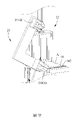
請參考圖1至圖4,其為本發明所提供之束帶儲存裝置10較佳實施例。透過一控制系統的調控,使得儲存有至少一個束帶16的該束帶儲存裝置10可以將其中一個該束帶16傳遞至一束帶綁設裝置20。該束帶綁社裝置20進一步的可以將其中一束帶16移動至可以容置一晶圓且疊層放置的一個以上暫存盤A附近,並執行將該束帶16綁束疊層放置的一個以上該暫存盤A外周面之動作。 Please refer to FIG. 1 to FIG. 4 , which are preferred embodiments of the belt storage device 10 provided by the present invention. Through the regulation of a control system, the strap storage device 10 storing at least one strap 16 can transfer one of the straps 16 to a strap binding device 20 . The strap binding device 20 can further move one of the straps 16 to the vicinity of more than one temporary storage disk A that can accommodate a wafer and place it stacked, and perform a step of bundling the strap 16 and stacking it. The above actions on the outer peripheral surface of the temporary storage disk A.

該束帶儲存裝置10包含有至少一個容置空間11、一個以上儲存盤12、至少一個頂升機構13、一抓取單元14以及一輸出單元15。於該容置空間11內由下至上的依序層疊放置有一個以上該儲存盤12,該頂升機構13可以上下的移動層疊放置的一個以上該儲存盤12,使得最上方的該儲存盤12可以位移至該束帶儲存裝置10的頂面。該抓取單位14抓取該容置空間11中最上方的該儲存盤12,並移動至該輸出單元15。 The strap storage device 10 includes at least one accommodating space 11 , more than one storage tray 12 , at least one jacking mechanism 13 , a grabbing unit 14 and an output unit 15 . In the accommodating space 11, there are more than one storage trays 12 stacked in sequence from bottom to top, and the jacking mechanism 13 can move up and down the stacked storage trays 12, so that the uppermost storage tray 12 Can be displaced to the top surface of the belt storage device 10 . The grabbing unit 14 grabs the uppermost storage tray 12 in the accommodating space 11 and moves to the output unit 15 .

請配合參考圖2以及圖3,該儲存盤12包含有一儲存空間121,該儲存空間121中係儲存有至少一個該束帶16,其中,該儲存盤12可為一盤狀物,該盤狀物之上方可以構成水平延伸的該儲存空間121;該儲存盤12也可為一四邊框形,其框形內便可以界定為該儲存空間121。該束帶16以其一相對短邊之方向直立於該儲存盤12所構成的該儲存空間121,較佳的,該束帶16以其該相對短邊的方向垂直於該儲存空間121。 Please refer to FIG. 2 and FIG. 3, the storage tray 12 includes a storage space 121, and at least one of the straps 16 is stored in the storage space 121, wherein the storage tray 12 can be a disc-shaped object, and the disc-shaped The horizontally extending storage space 121 can be formed above the objects; The belt 16 is upright in the storage space 121 formed by the storage tray 12 along the direction of a relatively short side thereof. Preferably, the belt 16 is perpendicular to the storage space 121 along the direction of the relatively short side.

本實施例中,該儲存盤12為一方形板體,該儲存盤12的一上表面設置有至少一定位件122,該定位件122沿該儲存盤12其中一長度方向設置,該 定位件122較佳的為一塊體,且其表面凹設有至少一溝槽123,使得該束帶16可以利用其中一相對長邊插設於該溝槽123內,如此便可以利用該溝槽123的支撐將該束帶16以其該相對短邊方向的直立於該儲存盤12上方所構成該儲存空間121。 In this embodiment, the storage tray 12 is a square plate body, and at least one positioning member 122 is provided on an upper surface of the storage tray 12, and the positioning member 122 is arranged along one of the lengthwise directions of the storage tray 12. The positioning member 122 is preferably one piece, and its surface is concavely provided with at least one groove 123, so that the belt 16 can be inserted into the groove 123 by using one of the relatively long sides, so that the groove can be used The support of 123 forms the storage space 121 by standing the strap 16 upright above the storage tray 12 in the direction of the relatively short sides.

該儲存盤12與該定位件122並無限定為二個分開的元件,該儲存盤12與該定位件122也可為一體成行設置。本實施例中,二個該定位件122平行的設置於該儲存空間121,且二個該定位件122的各該溝槽123相互對應設置,二個該定位件112之間形成之距離小於等於該束帶16之長度。如此,該束帶16便可以利用其該相對長邊之兩端插設於位置相互對應的二個該溝槽123內,達到以該相對短邊直立於該儲存空間121之型態。 The storage tray 12 and the positioning member 122 are not limited to two separate components, and the storage tray 12 and the positioning member 122 can also be arranged in a row as one. In this embodiment, the two positioning members 122 are arranged in parallel in the storage space 121, and the grooves 123 of the two positioning members 122 are arranged corresponding to each other, and the distance formed between the two positioning members 112 is less than or equal to The length of the strap 16. In this way, the belt 16 can be inserted into the two grooves 123 corresponding to each other by using the two ends of the relatively long sides, so as to achieve the configuration of standing upright in the storage space 121 with the relatively short sides.

進一步的,該束帶16的該相對長邊包含有位於相對兩端的一穿設端161與一自由端162,以及形成於該束帶16表面的一魔鬼氈結構,其中,該穿設端161包含有一金屬環163。該束帶16放置於該儲存盤12上時,該穿設端161以及該自由端162分別放置於二個該定位件122相互對應的該溝槽123。該束帶16的長度會依據欲綁束的該暫存盤A的大小以及該暫存盤A層疊放置的數量所構成之外周圍大小而有所不同,因此二個該定位件122之間所形成的距離也會依據該束帶16的長度而有所調整。 Further, the relatively long side of the belt 16 includes a piercing end 161 and a free end 162 located at opposite ends, and a Velcro structure formed on the surface of the belt 16, wherein the piercing end 161 Contains a metal ring 163 . When the belt 16 is placed on the storage tray 12 , the through end 161 and the free end 162 are respectively placed in the corresponding grooves 123 of the two positioning members 122 . The length of the strap 16 will vary according to the size of the temporary storage disk A to be bound and the size of the outer circumference formed by the number of the temporary storage disk A stacked. Therefore, the space formed between the two positioning members 122 The distance will also be adjusted according to the length of the strap 16 .

較佳的,設置有一固定元件124於各該溝槽123內,使得該束帶16插入於各該溝槽123內時,該固定元件124可以使得該束帶16穩定於各該溝槽123內,不易掉落,該固定元件124可以是吸引該金屬環163的一磁鐵1241、一吸真空元件或是一抵靠元件。 Preferably, a fixing element 124 is provided in each of the grooves 123, so that when the belt 16 is inserted into each of the grooves 123, the fixing element 124 can stabilize the belt 16 in each of the grooves 123 , not easy to drop, the fixing element 124 can be a magnet 1241 attracting the metal ring 163, a vacuum element or an abutting element.

以該固定元件124為該磁鐵1241為例,於該定位件122的各該溝槽123底部各設置有一磁鐵1241,如此,該磁鐵1241便可以利用磁性,使得束帶16的該金屬環163與其吸引固定,不僅可以防止該束帶16掉落,更可以維持該束帶 16以短邊方向直立於該儲存空間121之型態,整齊同方向並一致性的排列一個以上該束帶16。 Taking the fixing element 124 as the magnet 1241 as an example, a magnet 1241 is respectively arranged at the bottom of each of the grooves 123 of the positioning member 122, so that the magnet 1241 can use magnetism to make the metal ring 163 of the band 16 and its Attracting and fixing not only can prevent the strap 16 from falling, but also maintain the strap 16 is in the form of standing upright in the storage space 121 in the short side direction, and more than one belt 16 is arranged in the same direction and consistent.

以該固定元件124為該吸真空元件或該抵靠元件為例,於各該溝槽123之槽壁上皆設置該吸真空元件或該抵靠元件。當該束帶16插入於各該溝槽123內時,該吸真空元件便可以利用真空吸力吸住該束帶16之其中一側面;而該抵靠元件則是可以展現抵壓該束帶16之其中一該側面,進而固定該束帶16於各該溝槽123內。 Taking the fixing element 124 as the vacuum element or the abutting element as an example, the vacuum element or the abutting element is provided on the groove wall of each of the grooves 123 . When the belt 16 is inserted into each of the grooves 123, the vacuum element can absorb one side of the belt 16 by vacuum suction; One of the side surfaces, and then fix the strap 16 in each of the grooves 123 .

本實施例中,二個該定位件122的該固定元件124分別為該磁鐵1241以及該吸真空元件,如此,便可以利用該磁鐵1241固定該束帶16的該穿設端161以及金屬環163;並利用該吸真空元件固定該束帶16的該自由端162,不僅可以更佳的穩定該束帶16,更可以確保該束帶16可以垂直於該儲存空間121。 In this embodiment, the fixing elements 124 of the two positioning members 122 are respectively the magnet 1241 and the vacuum-absorbing element, so that the passing end 161 and the metal ring 163 of the belt 16 can be fixed by using the magnet 1241 and using the vacuum element to fix the free end 162 of the strap 16 can not only better stabilize the strap 16, but also ensure that the strap 16 can be perpendicular to the storage space 121.

該頂升機構13設置於該容置空間11內,該頂升機構13包含垂直於水平面的一頂升軌道131以及沿該頂升軌道131上下移動的一頂升基座132,其中一個以上該儲存盤12依序層疊的放置於該頂升基座132上,如此該頂升基座132便可以由下至上的於該容置空間中移動層疊放置的一個以上該儲存盤12,使得最上方的該儲存盤12可以位移至該束帶儲存裝置10的頂面。 The jacking mechanism 13 is arranged in the accommodating space 11, and the jacking mechanism 13 includes a jacking rail 131 perpendicular to the horizontal plane and a jacking base 132 moving up and down along the jacking rail 131, wherein more than one of the The storage trays 12 are sequentially stacked on the lifting base 132, so that the lifting base 132 can move more than one storage tray 12 stacked in the accommodating space from bottom to top, so that the uppermost The storage tray 12 can be displaced to the top surface of the strap storage device 10 .

較佳的,該束帶儲存裝置10包含有外型為長方框體的一本體10A,該本體10A內部至少一部分形成為該容置空間11,該輸出單元15設置於該容置空間11旁側,該抓取單元14設置於該容置空間11以及該輸出單元15上方,且該抓取單元14可於該容置空間11以及該輸出單元15之間往返運行。該抓取單元14包含一第一抓取軌道141以及沿該第一抓取軌道141移動的一抓取件142,且該第一抓取軌道141沿該容置空間11以及該輸出單元15之位置對應設置。該抓取件142為一類長桿狀,其兩端分別為相互對應設置的一第一抓取端以及一第二抓 取端。該第一抓取端可以相對該第二抓取端靠近或遠離,且該第一抓取端以及該第二抓取端所構成之方向與該儲存盤12的至少一長邊平行。 Preferably, the strap storage device 10 includes a body 10A in the shape of a rectangular frame, at least a part of the interior of the body 10A is formed as the accommodating space 11 , and the output unit 15 is arranged beside the accommodating space 11 On the side, the grabbing unit 14 is disposed above the accommodating space 11 and the output unit 15 , and the grabbing unit 14 can run back and forth between the accommodating space 11 and the output unit 15 . The grabbing unit 14 includes a first grabbing track 141 and a grabbing member 142 moving along the first grabbing track 141 , and the first grabbing track 141 is along the path between the accommodating space 11 and the output unit 15 The location corresponds to the setting. The grasping part 142 is a kind of long rod shape, and its two ends are respectively a first grasping end and a second grasping end which are arranged corresponding to each other. Take the end. The first grabbing end can approach or move away from the second grabbing end, and the direction formed by the first grabbing end and the second grabbing end is parallel to at least one long side of the storage tray 12 .

一延伸裝置145形成於該抓取件142上,該延伸裝置145可以依據所需,上下調整該抓取件142相對於該容置空間11以及該輸出單元15之距離。當該抓取件142欲抓取該容置空間11中最上方的該儲存盤12時,該抓取件142沿著該第一抓取軌道141移動至該容置空間11上方,此時該第一抓取端與該第二抓取端之間所構成的距離略大於該儲存盤12的至少一該長邊。 An extension device 145 is formed on the gripper 142 , and the extension device 145 can adjust up and down the distance of the gripper 142 relative to the accommodating space 11 and the output unit 15 as required. When the grabbing member 142 intends to grab the uppermost storage tray 12 in the accommodating space 11, the grabbing member 142 moves to the top of the accommodating space 11 along the first grabbing track 141, and the A distance formed between the first grabbing end and the second grabbing end is slightly larger than at least one of the long sides of the storage tray 12 .

接著,該延伸裝置145使得該抓取件142可以朝向該容置空間11方向延伸,使得該第一抓取端與該第二抓取端可以朝下移動並對應該儲存盤12的該長邊兩端,接著,該第一抓取端相對該第二抓取端靠近,抓取最上方的該儲存盤12。該延伸裝置145進一步的可以使該抓取件142遠離該容置空間11,最後,該抓取件142便可以沿該第一抓取軌道141移動至該輸出單元15。 Next, the extension device 145 enables the gripper 142 to extend toward the accommodating space 11 , so that the first gripper end and the second gripper end can move downward and correspond to the long side of the storage tray 12 Then, the first grabbing end approaches the second grabbing end to grab the uppermost storage tray 12 . The extension device 145 can further keep the grabbing member 142 away from the accommodating space 11 , and finally, the grabbing member 142 can move to the output unit 15 along the first grabbing track 141 .

該第一抓取端以及該第二抓取端的型態並不限定,其可以是一夾嘴,並且於抓取該儲存盤12時,夾持該儲存盤12的其中一對邊。本實施例中,該第一抓取端143與該第二抓取端144分別為朝下延伸的一檔板。該第一抓取端與該第二抓取端的一自由端相互對應並水平沿伸的形成有一拖盤件。使得該第一抓取端與該第二抓取端以及二個該拖盤件之間可以構成有一抓取空間。 The shapes of the first grabbing end and the second grabbing end are not limited, they may be a gripper, and when grabbing the storage tray 12 , grip a pair of sides of the storage tray 12 . In this embodiment, the first grabbing end 143 and the second grabbing end 144 are respectively a baffle extending downward. A free end of the first grabbing end and the second grabbing end correspond to each other and extend horizontally to form a tray member. A grabbing space can be formed between the first grabbing end, the second grabbing end and the two tray parts.

如此,該第一抓取端與該第二抓取端並對應該儲存盤12的該對邊相互靠近時,二個該檔板分別的抵靠於該對邊,且二個該拖盤件分別的至該對邊插入於最上方該儲存盤12的下方,使得上方該儲存盤12得以容納於該抓取空間內,如此該儲存盤12經由該一抓取單元14移動時,便可以經由二個該拖盤件穩定支撐,保持水平不怕傾倒。 In this way, when the first grabbing end and the second grabbing end and corresponding to the opposite sides of the storage tray 12 are close to each other, the two baffle plates respectively abut against the opposite sides, and the two tray members The opposite sides are respectively inserted under the uppermost storage tray 12, so that the upper storage tray 12 can be accommodated in the grabbing space, so that when the storage tray 12 moves through the grabbing unit 14, it can pass through The two tray parts are stably supported and kept level without being afraid of toppling over.

該輸出單元15承接經由該抓取單位14釋放的該儲存盤12,並且將該儲存盤12運送至該束帶儲存裝置10外,該輸出單元15包含有一輸出軌道151以 及沿著該輸出軌道151移動的一承接基座152。該輸出軌道151的一運輸方向並不限定,可以依照運送該儲存盤12的需求,決定該輸出方向。該承接基座152之上方形成有一平面,係用於承接該儲存盤12,保持該儲存盤12水平運行。 The output unit 15 accepts the storage tray 12 released by the grasping unit 14, and transports the storage tray 12 to the outside of the strap storage device 10. The output unit 15 includes an output track 151 for And a receiving base 152 that moves along the output rail 151 . A transport direction of the output track 151 is not limited, and the output direction can be determined according to the requirement of transporting the storage tray 12 . A plane is formed above the receiving base 152 for receiving the storage tray 12 to keep the storage tray 12 running horizontally.

當該抓取單位14欲抓取該儲存盤12移動至該輸出單元15時,該抓取單位14移動至該承接基座152上方,該延伸裝置1435使得該抓取件1432朝向該承接基座152方向延伸,使得該儲存盤12可以朝下移動並放置於該承接基座152上方,接著,該第一抓取端1433相對該第二抓取端1434遠離,便可以釋放該儲存盤12。 When the grabbing unit 14 intends to grab the storage tray 12 and move to the output unit 15, the grabbing unit 14 moves above the receiving base 152, and the extension device 1435 makes the grabbing member 1432 face the receiving base 152 , so that the storage tray 12 can move downward and be placed on the receiving base 152 , and then, the first gripping end 1433 moves away from the second gripping end 1434 , so that the storage tray 12 can be released.

該束帶儲存裝置10並不限定該容置空間11的數量,也並不限定該容置空間11與該輸出單元15之間的相對位置。舉例而言,該本體10A(該長方框體)內的一長邊方向之兩端各分別設置有一個該容置空間11,而該輸出單元15設置於二個該容置空間11之間,且該第一抓取軌道141沿著該長邊方向設置於該本體10A上方,而該輸出單元15的該運輸方向與該長邊方向垂直。如此位於中間的該輸出單元15與二個該容置空間11之距離皆相等,便可以減少該第一抓取軌道141來回移動的距離,並且提高該束帶儲存裝置10移動該儲存盤12的效率。 The strap storage device 10 does not limit the number of the accommodating spaces 11 , nor does it limit the relative positions between the accommodating spaces 11 and the output unit 15 . For example, one accommodating space 11 is respectively provided at both ends of a longitudinal direction in the main body 10A (the rectangular frame body), and the output unit 15 is arranged between the two accommodating spaces 11 , and the first grabbing track 141 is disposed above the main body 10A along the longitudinal direction, and the transport direction of the output unit 15 is perpendicular to the longitudinal direction. In this way, the distance between the output unit 15 located in the middle and the two accommodating spaces 11 is equal, so that the distance for the first grabbing track 141 to move back and forth can be reduced, and the speed of the belt storage device 10 moving the storage tray 12 can be improved. efficiency.

更佳的,該容置空間11亦不限定該頂升機構13的數量,本實施例中,每個該容置空間11中,以該本體10A(該長方框體)的另一長邊方向間隔排列有三個該頂升機構13,且該抓取單元14進一步的包含沿著三個該頂升機構13排列方向設置的一第二抓取軌道141A,其中該抓取件142可以沿該第二抓取軌道141A之設置方向來回於三個該頂升機構13上方移動。較佳的該第二抓取軌道141A可以沿著該第一抓取軌道141移動,進而帶動該抓取件142於該容置空間11以及該輸出單元15之間往返運行。如此,便可以利用複數個該頂升機構13的設置,增加該儲存盤12以及該束帶16的儲存量,也可以依據所需,將不同長度的該束帶16分類存放,達到有效的束帶管理,且該第一抓取軌道141以及該第二抓 取軌道141A不同延伸方向的設置,更可以令該抓取件142的移動範圍大幅度提升,促進該束帶儲存裝置10整體實用性。 More preferably, the accommodating space 11 does not limit the number of the jacking mechanism 13. In this embodiment, in each accommodating space 11, the other long side of the main body 10A (the rectangular frame) There are three jacking mechanisms 13 arranged at intervals in the direction, and the grabbing unit 14 further includes a second grabbing track 141A arranged along the direction in which the three jacking mechanisms 13 are arranged, wherein the grabbing member 142 can move along the The setting direction of the second grab rail 141A moves back and forth above the three jacking mechanisms 13 . Preferably, the second grabbing track 141A can move along the first grabbing track 141 , and then drive the grabbing member 142 to run back and forth between the accommodating space 11 and the output unit 15 . Like this, just can utilize the setting of a plurality of this lifting mechanism 13, increase the storage capacity of this storage tray 12 and this drawstring 16, also can according to need, this drawstring 16 of different length is classified and stored, reaches effective drawstring. belt management, and the first grab track 141 and the second grab The arrangement of different extending directions of the track 141A can further greatly increase the moving range of the grabbing member 142 and improve the overall practicability of the strap storage device 10 .

請配合參考圖4以及圖6B,該束帶綁設裝置20包含有至少一個夾取機構21、一輸盤機構22以及一綁束機構23,該夾取機構21對應設置於該輸出軌道151遠離該束帶儲存裝置10之一輸出末端1511,該夾取機構21可選擇的夾取該儲存盤12上其中一個該束帶16,並朝向該輸盤機構22移動靠近。該輸盤機構22可至該束帶綁設裝置20外將疊層放置的一個以上該暫存盤A運送至該束帶綁設裝置20,並且位置對應該夾取機構21。該夾取機構21夾取該束帶16移動至鄰近該輸盤機構22處時,該束帶16位置得以對應於一個以上該暫存盤A的至少一外周面。該綁束機構23與該輸盤機構22相鄰設置,該綁束機構23至該夾取機構21取得該束帶16,並將束帶16綁設於一個以上該暫存盤A的外周圍。 Please refer to FIG. 4 and FIG. 6B, the strap binding device 20 includes at least one clamping mechanism 21, a delivery mechanism 22 and a binding mechanism 23, the clamping mechanism 21 is correspondingly arranged on the output track 151 away from One output end 1511 of the belt storage device 10 , the clamping mechanism 21 selectively clamps one of the belts 16 on the storage tray 12 , and moves toward the tray delivery mechanism 22 . The tray delivery mechanism 22 can transport the one or more temporary storage trays A placed in layers to the strap binding device 20 outside the strap binding device 20 , and the position corresponds to the clamping mechanism 21 . When the clamping mechanism 21 clamps the belt 16 and moves to a place close to the disk feeding mechanism 22 , the position of the belt 16 can correspond to at least one outer peripheral surface of more than one temporary storage disk A. The binding mechanism 23 is disposed adjacent to the disk feeding mechanism 22 , and the binding mechanism 23 obtains the belt 16 from the clamping mechanism 21 , and binds the belt 16 on the outer periphery of more than one temporary storage disk A.

進一步地配合參考圖5A,本發明較佳實施例中,該夾取機構21包含一移動軌道211、一第一夾取手臂212以及一第二夾取手臂213。該移動軌道211設置於該輸出末端1511上方,較佳的,該移動軌道211與該定位件122相互平行設置,該第一夾取手臂212可以沿該移動軌道211來回運行,使得該第一夾取手臂212可以依據所需,選擇性的夾取該儲存盤12上其中一個該束帶16。 Further referring to FIG. 5A , in a preferred embodiment of the present invention, the clamping mechanism 21 includes a moving track 211 , a first clamping arm 212 and a second clamping arm 213 . The moving track 211 is arranged above the output end 1511. Preferably, the moving track 211 and the positioning member 122 are arranged parallel to each other, and the first clamping arm 212 can run back and forth along the moving track 211, so that the first gripper The fetching arm 212 can selectively grip one of the straps 16 on the storage tray 12 according to needs.

進一步地,該第一夾取手臂212包含一第一基座2121、一長度延伸裝置2122以及二個第一夾爪2123,其中,該第一基座2121設置於該移動軌道211以及該長度延伸裝置2122之間,且該第一基座2121可以沿著該移動軌道211帶動該長度延伸裝置2122移動。該長度延伸裝置2122與該束帶16的該相對長邊方向平行的兩端並且分別的設置有一個該第一夾爪2123,該長度延伸裝置2122可以依據需求或是對應該束帶16之長度延展或是收縮,使得二個該第一夾爪2123之間的距離遠離或拉近。 Further, the first clamping arm 212 includes a first base 2121, a length extension device 2122 and two first jaws 2123, wherein the first base 2121 is set on the moving track 211 and the length extension between the devices 2122 , and the first base 2121 can drive the length extension device 2122 to move along the moving track 211 . The two ends of the length extension device 2122 parallel to the opposite longitudinal direction of the belt 16 are respectively provided with a first jaw 2123, and the length extension device 2122 can be according to requirements or corresponding to the length of the belt 16 The extension or contraction makes the distance between the two first clamping jaws 2123 farther or closer.

該長度延伸裝置2122的型態不限制,其可以是二個相互套接的二個桿狀物,透過二個該桿狀物相互的軸向運動,使得設置於兩端的該第一夾爪2123對應移動;該長度延伸裝置2122也可以是一螺桿,而其中一個該第一夾爪2123包含有一螺紋套環可移動的套設於該螺桿外周圍,透過一馬達轉動該螺桿,其中一個該第一夾爪2123邊可以相對著另一個該第一夾爪2123移動。本實施例中,該長度延伸裝置2122為二個相互套接的二個板狀物,透過二個該板狀物相互的軸向運動,使得設置於兩端的該第一夾爪2123對應移動,該板狀物的設置可以相對的提高該長度延伸裝置2122的機構穩定性。 The shape of the length extension device 2122 is not limited, it can be two rods nested in each other, through the mutual axial movement of the two rods, the first jaws 2123 arranged at both ends Corresponding movement; the length extension device 2122 can also be a screw rod, and one of the first clamping jaws 2123 includes a threaded collar that is movably sleeved around the screw rod, and the screw rod is rotated by a motor, and one of the first jaws 2123 One jaw 2123 can move relative to the other first jaw 2123 . In this embodiment, the length extension device 2122 is two plates that are nested in each other. Through the mutual axial movement of the two plates, the first jaws 2123 disposed at both ends move correspondingly. The setting of the plate can relatively improve the mechanical stability of the length extending device 2122 .

進一步地,該長度延伸裝置2122的兩端朝向該儲存盤12方向凸出設置有二個延伸板,二個該第一夾爪2123分別可轉動的設置於二個延伸板上,使得各該第一夾爪2123可以沿著各該延伸板朝向該儲存盤12靠近或遠離,並且相對二個延伸板轉動展現一第一狀態以及一第二狀態。該第一夾爪2123的自由端包含有成對設置的一夾嘴,以及形成於該夾嘴中間的一夾嘴開口,該夾嘴開口的大小依據該夾嘴的開啟或關閉改變。 Further, two extension plates protrude from both ends of the length extension device 2122 toward the storage tray 12, and the two first jaws 2123 are respectively rotatably disposed on the two extension plates, so that each second A clamping claw 2123 can approach or move away from the storage tray 12 along each of the extension plates, and rotate relative to the two extension plates to exhibit a first state and a second state. The free end of the first jaw 2123 includes a pair of jaws and a jaw opening formed in the middle of the jaws. The size of the jaw opening changes according to the opening or closing of the jaws.

接著,請配合參考圖5A至圖5C,其為該第一夾取手臂212於該儲存盤12上夾取其中一個該束帶16之步驟示意圖。於起始位時,各該第一夾爪2123的該夾嘴朝向該儲存盤12方向延伸,展現該第一狀態,且該夾嘴開口呈現開放的樣態。此時,成對的該夾嘴所構成的延伸方向垂直於該儲存盤12上的至少一個該束帶16。 Next, please refer to FIG. 5A to FIG. 5C , which are schematic diagrams of steps for the first clamping arm 212 to clamp one of the straps 16 on the storage tray 12 . At the initial position, the jaws of each of the first jaws 2123 extend toward the storage tray 12 , showing the first state, and the opening of the jaws is open. At this time, the extension direction formed by the pair of clips is perpendicular to at least one of the straps 16 on the storage tray 12 .

當該第一夾取手臂212欲夾取其中一個該束帶16時,各該第一夾爪2123經由該第一基座2121沿著該移動軌道211的移動,使得其中一個該束帶16得以對齊於各該第一夾爪2123上該夾嘴開口。較佳的,於此步驟時,該長度延伸裝置2122對應該束帶16之長度延展或是收縮,使得二個該第一夾爪2123之間的距離小於或等於該束帶16之長度。 When the first clamping arm 212 intends to clamp one of the belts 16, each of the first jaws 2123 moves along the moving track 211 via the first base 2121, so that one of the belts 16 can be Align with the jaw opening on each of the first jaws 2123 . Preferably, during this step, the length extending device 2122 extends or contracts corresponding to the length of the belt 16 , so that the distance between the two first jaws 2123 is less than or equal to the length of the belt 16 .

當該第一夾取手臂212位置對應至其中一個該束帶16時,各該第一夾爪2123沿著各該延伸板朝向該束帶16靠近,使得該束帶16位置於上方的該相對長邊可以位置於各該夾嘴開口內,且各該第一夾爪2123的成對的該夾嘴分別位置於該束帶16的兩側面,此時,二個該夾嘴相互靠近至並夾持該束帶16。當該夾嘴夾持該束帶16時,各該第一夾爪2123沿著各該延伸板移動,連帶該束帶16遠離該儲存盤12。較佳的,其中一個該第一夾爪2123夾持該束帶16該穿設端161的該金屬環163;另一個該第一夾爪2123則夾持該束帶16的自由端162末端,使得該第一夾取手臂212至各該溝槽123內移出該束帶16時,可以穩固的令該束帶16脫離該固定元件124。 When the position of the first gripping arm 212 corresponds to one of the straps 16, each of the first clamping jaws 2123 approaches the strap 16 along each of the extension plates, so that the strap 16 is located on the opposite upper side. The long sides can be positioned in the openings of the jaws, and the paired jaws of the first jaws 2123 are respectively positioned on both sides of the strap 16. At this time, the two jaws are close to each other and close to each other. The strap 16 is clamped. When the clip clamps the strap 16 , each of the first jaws 2123 moves along each of the extension plates, and the strap 16 is moved away from the storage tray 12 together. Preferably, one of the first jaws 2123 clamps the metal ring 163 of the piercing end 161 of the belt 16; the other first jaw 2123 clamps the end of the free end 162 of the belt 16, Therefore, when the first clamping arm 212 moves out of the belt 16 into each of the grooves 123 , the belt 16 can be stably separated from the fixing element 124 .

接著,如圖5B所示,二個該第一夾爪2123連帶著該束帶16相對二個該延伸板轉動90度,使得各該第一夾爪2123的該二夾嘴朝向遠離該束帶儲存裝置10之方向延伸,展現該第二狀態。進一步的,如圖5C箭頭方向所示,該第一夾取手臂212可以順應該移動軌道211的設置夾持該束帶16遠離該束帶儲存裝置10,較佳的,該第一夾取手臂212夾持該束帶16移動至鄰近該輸盤機構22處,更佳的,該第一夾取手臂212夾持該束帶16移動至鄰近該第二夾取手臂213位置處。 Next, as shown in FIG. 5B , the two first jaws 2123 are connected with the belt 16 and rotate 90 degrees relative to the two extension plates, so that the two jaws of each of the first jaws 2123 face away from the belt. The orientation of the storage device 10 extends to exhibit the second state. Further, as shown in the direction of the arrow in FIG. 5C, the first clamping arm 212 can follow the setting of the moving track 211 to clamp the strap 16 away from the strap storage device 10. Preferably, the first clamping arm 212 clamps the belt 16 and moves to a position adjacent to the disk delivery mechanism 22 , more preferably, the first clamping arm 212 clamps the belt 16 and moves to a position adjacent to the second clamping arm 213 .

請配合參考圖6A至圖6B,其為該第二夾取手臂213至該第一夾取手臂212取得其中一個該束帶16之步驟示意圖。該第二夾取手臂213主要作用為將該束帶16帶離該束帶儲存裝置10,並且將該束帶16位移至對應於一個以上該暫存盤A的至少一個該外周面。需注意的是,該第二夾取手臂213的設置並不限定,亦可以僅透過該第一夾取手臂212將該束帶16直接移動至鄰近該輸盤機構22處。 Please refer to FIG. 6A to FIG. 6B , which are schematic diagrams of steps for the second clamping arm 213 to the first clamping arm 212 to obtain one of the straps 16 . The second clamping arm 213 is mainly used to take the strap 16 away from the strap storage device 10 and displace the strap 16 to at least one peripheral surface corresponding to more than one temporary storage disk A. It should be noted that the setting of the second clamping arm 213 is not limited, and the belt 16 can be directly moved to the position adjacent to the tray delivery mechanism 22 only through the first clamping arm 212 .

該第二夾取手臂213的設置,可以使得該束帶綁設裝置20的整體流程更加順暢,減少動作之間的等待時間。例如,該第二夾取手臂213夾取其中 一個該束帶16後,於該第二夾取手臂213做動的過程中,該第一夾取手臂212可以同時間的執行復位的動作,並至該儲存盤12取得另一個該束帶16,使得該束帶綁設裝置20效率倍增。 The setting of the second clamping arm 213 can make the overall process of the belt binding device 20 smoother and reduce the waiting time between actions. For example, the second gripping arm 213 grips the After one belt 16, in the process of moving the second clamping arm 213, the first clamping arm 212 can perform a reset action at the same time, and obtain another belt 16 from the storage disk 12 , so that the efficiency of the belt binding device 20 is doubled.

該第二夾取手臂213的結構也並不限制,該第二夾取手臂213亦可以實質上的與該第一夾取手臂212相同。本實施例中,第二夾取手臂213包含一第二基座2131、二個第二軌道2132以及二個第二夾爪2133,其中,各該第二基座2131分別設置於各該第二軌道2132以及各該第二夾爪2133之間,使得各該第二基座2131可以分別沿著各該第二軌道2132帶動各該第二夾爪2133移動。 The structure of the second clamping arm 213 is not limited, and the second clamping arm 213 can also be substantially the same as the first clamping arm 212 . In this embodiment, the second clamping arm 213 includes a second base 2131, two second rails 2132 and two second jaws 2133, wherein each of the second bases 2131 is respectively set on each of the second Between the track 2132 and each second jaw 2133 , each second base 2131 can drive each second jaw 2133 to move along each second track 2132 .

二個該第二軌道2132,對齊成一直線的間隔設置,且該直線平行於二個該第一夾爪2123所形成之直線。二個該第二夾爪2133可以依據需求或是對應該束帶16之長度,使得各該第二基座2131沿著該第二軌道2132移動,調整二個該第二基座2131上該第二夾爪2133之間的距離。二個該第二軌道2132並不限定為分離之樣態,二個該第二軌道2132亦可以為一體之直線軌道,使得各該第二基座2131得以移動於其中。 The two second rails 2132 are arranged in a straight line at intervals, and the straight line is parallel to the straight line formed by the two first jaws 2123 . The two second clamping jaws 2133 can be according to the requirement or corresponding to the length of the belt 16, so that each of the second bases 2131 can move along the second track 2132, and adjust the second bases 2131 on the two second bases 2131. The distance between the two jaws 2133. The two second rails 2132 are not limited to being separated, and the two second rails 2132 can also be integrated linear rails, so that each of the second bases 2131 can move therein.

二個該第二夾爪2133分別可轉動的設置於二個該第二基座2131上,使得各該第二夾爪2133可以相對該第二基座2131轉動。各該第二夾爪2133的自由端亦包含有成對的一第二夾嘴,以及形成於該第二夾嘴之間的一第二夾嘴開口,該第二夾嘴開口之大小依據該第二夾嘴的開啟或關閉改變。 The two second clamping jaws 2133 are respectively rotatably disposed on the two second bases 2131 , so that each of the second clamping jaws 2133 can rotate relative to the second base 2131 . The free ends of each of the second jaws 2133 also include a pair of second jaws, and a second jaw opening formed between the second jaws, the size of the second jaw opening is according to the The opening or closing of the second jaw changes.

於起始位時,各該第二夾爪2133的該第二夾嘴朝向該第一夾取手臂212方向延伸,且各該第二夾嘴開口呈現開放樣態。此時,該第二夾嘴延伸方向對應於展現該第二狀態的該夾嘴延伸方向。較佳的,二個該第二夾爪2133依據該第一夾取手臂212所夾持的該束帶16之長度,調整其之間的距離至小於或等於該束帶16之長度。 At the initial position, the second jaws of each of the second jaws 2133 extend toward the direction of the first gripping arm 212 , and the openings of each second jaws are open. At this time, the second extending direction of the clip corresponds to the extending direction of the clip exhibiting the second state. Preferably, the distance between the two second clamping claws 2133 is adjusted to be less than or equal to the length of the belt 16 according to the length of the belt 16 clamped by the first clamping arm 212 .

配合參考圖5C,當該第一夾取手臂212順應該移動軌道211位移時,該第一夾取手臂212移動至鄰近該第二夾取手臂213位置,使得該束帶16的另一該相對長邊可以相對的位置於各該第二夾嘴開口內,且成對的該第二夾嘴分別位置於該束帶16的兩側面,接著,該第二夾嘴相互靠近即可夾持該束帶16。較佳的,二個各該第二夾爪2133與該第一夾爪2123夾持該束帶16之部位相互錯開,使得該第一夾取手臂212與該第二夾取手臂213不會相互干擾。 With reference to FIG. 5C, when the first clamping arm 212 is displaced along the moving track 211, the first clamping arm 212 moves to a position adjacent to the second clamping arm 213, so that the other side of the strap 16 is opposite The long sides can be positioned opposite to each other in the openings of the second jaws, and the pairs of the second jaws are respectively located on both sides of the strap 16, and then the second jaws can be clamped when they are close to each other. drawstring16. Preferably, the positions where the two second clamping jaws 2133 and the first clamping jaws 2123 clamp the belt 16 are staggered from each other, so that the first clamping arm 212 and the second clamping arm 213 will not interact with each other. interference.

接著,如圖6B所示,二個該第二夾爪2133連帶著該束帶16相對二個該第二基座2131轉動180度,使得各該第二夾爪2133的該第二夾嘴朝向該輸盤機構22方向,較佳的,各該第二夾爪2133夾持該束帶16相對該第二基座2131轉動,使得該束帶16對應於一個以上該暫存盤A的至少一個該外周面,更佳的,各該第二夾爪2133相對該第二基座2131轉動,使得該束帶16對應於一個以上該暫存盤A的一底面。 Then, as shown in FIG. 6B , the two second jaws 2133 together with the belt 16 rotate 180 degrees relative to the two second bases 2131, so that the second jaws of each second jaw 2133 face toward In the direction of the disk delivery mechanism 22, preferably, each of the second clamping claws 2133 clamps the belt 16 and rotates relative to the second base 2131, so that the belt 16 corresponds to at least one of the temporary storage disks A. On the outer peripheral surface, more preferably, each second clamping claw 2133 rotates relative to the second base 2131 , so that the belt 16 corresponds to a bottom surface of more than one temporary storage disk A.

請配合參考圖7A至圖7F,其為該綁束機構23將其中一個該束帶16綁設於一個以上該暫存盤A外周圍之步驟示意圖。該綁束機構23與該輸盤機構22相鄰設置,該輸盤機構22較佳的包含有一輸盤件221、一輸盤軌道222以及一抵壓元件223。 Please refer to FIG. 7A to FIG. 7F , which are schematic diagrams of steps for the binding mechanism 23 to bind one of the straps 16 around the outer periphery of more than one temporary storage disk A. The binding mechanism 23 is disposed adjacent to the tray delivery mechanism 22 , and the tray delivery mechanism 22 preferably includes a tray delivery member 221 , a tray delivery track 222 and a pressing element 223 .

該輸盤件221可以連帶的一個以上該暫存盤A於該輸盤軌道222中移動,使疊層放置的一個以上該暫存盤A可以透過該輸盤件221運送至位置對應該第二夾取手臂213處。一個以上該暫存盤A疊層的放置於該輸盤件221之上表面,且一個以上該暫存盤A的其中一端突出於該輸盤件221,較佳的,一個以上該暫存盤A的其中一端,朝向該第二夾取手臂213方向突出於該輸盤件221。 The feeding tray 221 can move together with more than one temporary storage disk A in the feeding tray track 222, so that more than one temporary storage disk A stacked can be transported through the feeding tray 221 to the position corresponding to the second gripper. Arm 213. More than one temporary storage disk A is stacked on the upper surface of the delivery tray 221, and one end of the more than one temporary storage tray A protrudes from the delivery tray 221, preferably, one of the more than one temporary storage tray A One end protrudes from the delivery disk member 221 toward the direction of the second clamping arm 213 .

該抵壓元件223可以提供一壓力使得一個以上該暫存盤A可以穩定的疊層放置於該輸盤件221之上表面,避免移動時產生搖晃不穩甚至是碰撞損傷。本實施例中,該抵壓元件223包含有一支撐架2231以及一抵壓桿2232,該支 撐架2231包含朝上突出並間隔設置於該輸盤件221上表面的至少二個支撐桿以及連接二個支撐桿並平行該輸盤件221的一頂板,使得該支撐架2331呈現一類ㄇ型結構設置於該輸盤件221上,其中,至少二個間隔設置的該支撐桿距離大於一個以上該暫存盤A的其中一長邊距離,使得一個以上該暫存盤A得以容置於該支撐架2231與該輸盤件221之間所構成之一拖盤空間內。該抵壓桿2232可活動的穿設於該頂板,使得該抵壓桿2232的其中一端可以抵靠於一個以上該暫存盤A之上表面,並提供一壓力達到穩定疊層放置一個以上該暫存盤A之功能。 The pressing element 223 can provide a pressure so that more than one temporary storage disk A can be stably stacked on the upper surface of the transporting disk member 221 to avoid shaking or even collision damage during movement. In this embodiment, the pressing element 223 includes a support frame 2231 and a pressing rod 2232, the support The bracket 2231 includes at least two support rods that protrude upward and are arranged at intervals on the upper surface of the tray 221, and a top plate that connects the two support rods and is parallel to the tray 221, so that the support frame 2331 presents a ㄇ-shaped The structure is arranged on the tray member 221, wherein the distance between at least two support rods arranged at intervals is greater than the distance between one of the long sides of more than one temporary storage disk A, so that more than one temporary storage disk A can be accommodated in the support frame 2231 and the tray member 221 formed between a tray space. The pressing rod 2232 is movable through the top plate, so that one end of the pressing rod 2232 can abut against the upper surface of more than one temporary storage tray A, and provide a pressure to stably stack and place more than one temporary storage disk A. The function of saving disk A.

配合參考圖6B,該綁束機構23包含二個自動手臂231,且二個該自動手臂231分別設置於該輸盤機構22之兩側,並且對應該第二夾取手臂213。二個該自動手臂231並無限定其樣態,二個該自動手臂231之目的為當該第二夾取手臂213夾持該束帶16移動至對應於一個以上該暫存盤A的一底面時,二個該自動手臂231可以分別至二個該第二夾爪2133夾取其中一個該束帶16的該穿設端161與該自由端162。 With reference to FIG. 6B , the binding mechanism 23 includes two automatic arms 231 , and the two automatic arms 231 are respectively arranged on two sides of the disk delivery mechanism 22 and correspond to the second clamping arm 213 . The shape of the two automatic arms 231 is not limited. The purpose of the two automatic arms 231 is when the second clamping arm 213 clamps the belt 16 and moves to a bottom surface corresponding to more than one temporary storage disk A. The two automatic arms 231 can respectively clamp the passing end 161 and the free end 162 of one of the belts 16 to the two second jaws 2133 .

如圖7A所示,二個該自動手臂231之自由端皆包含有一旋轉基座2311,該旋轉基座2311之自由端界定有一平面,且該旋轉基座2311可以該平面為基準地旋轉,使得該平面得以順時鐘或逆時鐘的轉動。各該平面上設置有至少一個自動夾嘴2312,使得二個該自動手臂231可以透過該旋轉基座2311轉動至少一個該自動夾嘴2312,使其可以於綁社該束帶16時,依據需求使得各該自動夾嘴2312得以展現各種角度以及方向的夾取該束帶16。 As shown in Figure 7A, the free ends of the two automatic arms 231 all include a rotating base 2311, the free ends of the rotating base 2311 define a plane, and the rotating base 2311 can be rotated on the basis of the plane, so that The plane can be rotated clockwise or counterclockwise. Each of the planes is provided with at least one automatic gripper 2312, so that the two automatic arms 231 can rotate at least one of the automatic grippers 2312 through the rotating base 2311, so that when the belt 16 is tied, according to the demand Each of the automatic gripper mouths 2312 can exhibit various angles and directions to grip the belt 16 .

於本實施例中,二個該自動手臂231進一步的可以界定為一第一自動手臂231A以及一第二自動手臂231B。而該第一自動手臂231A進一步的包含成對的一第一自動夾嘴2312A以及成對的一第二自動夾嘴2312B,且該第一自動夾嘴2312A以及該第二自動夾嘴2312B分別所構成的一夾取方向相互垂直。該第 一自動夾嘴2312A與該第二自動夾嘴2312B之間距離並不限制,本實施例中,該第一自動夾嘴2312A與該第二自動夾嘴2312B相鄰設置 In this embodiment, the two automatic arms 231 can be further defined as a first automatic arm 231A and a second automatic arm 231B. And the first automatic arm 231A further includes a pair of a first automatic gripper 2312A and a pair of a second automatic gripper 2312B, and the first automatic gripper 2312A and the second automatic gripper 2312B respectively The formed clamping directions are perpendicular to each other. The first The distance between the first automatic jaw 2312A and the second automatic jaw 2312B is not limited. In this embodiment, the first automatic jaw 2312A is adjacent to the second automatic jaw 2312B.

該第二自動手臂231B則包含成對的一第三自動夾嘴2312C以及成對的一第四自動夾嘴2312D,其中,成對的該第三自動夾嘴2312C所構成之相互對應的二個夾面2313具備凹凸對應的一表面,舉例來說,該二個夾面2313朝其延伸方向的形成有凹凸對應一曲形表面。本實施例中,該第三自動夾嘴2312C的其中一個該夾面2313突出有一V型凸塊,該V型凸塊兩側所形成之斜面沿該夾面之延伸方向排列,而另一個該夾面2313則朝內凹設有一V型凹槽,且該V型凸塊以及該V型凹槽結構相互咬和。 The second automatic arm 231B then includes a pair of third automatic jaws 2312C and a pair of fourth automatic jaws 2312D, wherein the paired third automatic jaws 2312C constitute two corresponding The clamping surfaces 2313 have a surface corresponding to concavities and convexities. For example, the two clamping surfaces 2313 are formed with concavities and convexities corresponding to a curved surface along the extending direction thereof. In this embodiment, one of the clamping surfaces 2313 of the third automatic clamping mouth 2312C protrudes from a V-shaped protrusion, and the slopes formed on both sides of the V-shaped protrusion are arranged along the extending direction of the clamping surface, while the other The clamping surface 2313 is concavely provided with a V-shaped groove, and the V-shaped protrusion and the V-shaped groove structure are engaged with each other.

當該第一自動手臂231A以及該第二自動手臂231B分別的欲夾取該第二夾取手臂213上該束帶16的該穿設端161與該自由端162時,該第一自動手臂231A以及該第二夾取手臂213分別的以該第一自動夾嘴2312A以及該第三自動夾嘴2312C夾取該穿設端161與該自由端162,其中,該第一自動手臂231A夾取於該束帶16與該金屬環163之間的連接處,使得該金屬環163經由該第一自動手臂231A夾束固定,不會隨意擺盪位移。該第二自動手臂231A夾取該自由端162時,該束帶16之自由端162末段部分裸露,形成一裸露段164,且凹凸對應的二個該夾面2313,使得該束帶16得以對應二個該夾面2313夾合以該裸露段164的該相對短邊方向的呈現V型凹曲。 When the first automatic arm 231A and the second automatic arm 231B intend to grip the piercing end 161 and the free end 162 of the strap 16 on the second clamping arm 213 respectively, the first automatic arm 231A And the second clamping arm 213 respectively clamps the piercing end 161 and the free end 162 with the first automatic clamping mouth 2312A and the third automatic clamping nozzle 2312C, wherein the first automatic arm 231A clamps on The connection between the belt 16 and the metal ring 163 is such that the metal ring 163 is clamped and fixed by the first automatic arm 231A, and will not swing and shift randomly. When the second automatic arm 231A clamps the free end 162, the end section of the free end 162 of the belt 16 is partially exposed, forming a bare section 164, and the two clamping surfaces 2313 corresponding to the concave and convex, so that the belt 16 can be Corresponding to the two clamping surfaces 2313 clamping, the exposed segment 164 presents a V-shaped concave curvature in the direction of the relative short side.

接著,該第一自動手臂231A以及該第二自動手臂231B分別的帶動該束帶16的該穿設端161與該自由端162朝該暫存盤A的一頂面位移,使得該束帶16可以至該底面朝上的環繞該暫存盤A。此時,該第一自動夾嘴2312A夾束該金屬環163並使其朝上方直立,該第三自動夾嘴2312C夾取該裸露段164使其水平並對齊該金屬環163,由於該束帶16對應二個該夾面2313夾合而呈現V型凹曲, 使得裸露段164產生一結構強度,不至於水平時下垂墜彎曲而無法對齊該金屬環163。 Then, the first automatic arm 231A and the second automatic arm 231B respectively drive the piercing end 161 and the free end 162 of the belt 16 to move toward a top surface of the temporary storage disk A, so that the belt 16 can be Surround the scratch disk A with the bottom facing up. At this time, the first automatic clamping mouth 2312A clamps the metal ring 163 and makes it stand upright, and the third automatic clamping mouth 2312C clamps the exposed section 164 to make it horizontal and align with the metal ring 163, because the strap 16 corresponds to the clamping of two clamping surfaces 2313 to present a V-shaped concave curvature, This makes the exposed section 164 produce a structural strength, so that the metal ring 163 cannot be aligned with the metal ring 163 because it will not hang down and bend when it is horizontal.

請參考圖7B以及圖7C,該第二自動手臂231B帶動該裸露段164穿入該金屬環163後,該第一自動手臂231A釋放該束帶16,也因為該裸露段164具備該結構強度,使得該裸露段164可以支撐該金屬環163掛設於其中。接著,該第一自動手臂231A利用其該第二自動夾嘴2312B夾持該裸露段164,且第三自動夾嘴2312C釋放該束帶16。該第一自動手臂231A接著帶動該自由端162朝向該第一自動手臂231A的位置方向位移。 Please refer to FIG. 7B and FIG. 7C, after the second automatic arm 231B drives the exposed section 164 to penetrate the metal ring 163, the first automatic arm 231A releases the belt 16, also because the exposed section 164 has the structural strength, The bare section 164 can support the metal ring 163 to hang therein. Then, the first automatic arm 231A uses its second automatic gripper 2312B to grip the bare section 164 , and the third automatic gripper 2312C releases the strap 16 . The first automatic arm 231A then drives the free end 162 to move toward the position of the first automatic arm 231A.

較佳的,該自由端162的延伸方向與該暫存盤A的該頂面之間呈現一角度關係D,且該角度介於10度至60度之間。該束帶16藉由該第一自動手臂231A的帶動位移,逐步的環繞貼合於該暫存盤A的環周圍,也因為該自由端162的延伸方向與該頂面的該角度關係D,使得該金屬環163朝向該暫存盤A的該頂面靠攏,更佳的,該金屬環163抵靠於該頂面與其中一環側面連接的側邊。其中,該第二自動夾嘴2312B夾持該裸露段164時呈現有一第一夾持角度B,該第一夾持角度B的角度以及方向並不限制,該第一夾持角度B的形成有助於該第一自動手臂231A給予該束帶16一張力,使的該束帶16逐漸貼和並環繞該暫存盤A。 Preferably, an angle relationship D exists between the extending direction of the free end 162 and the top surface of the temporary storage disk A, and the angle is between 10 degrees and 60 degrees. The belt 16 is driven and displaced by the first automatic arm 231A, and gradually wraps around and fits around the ring of the temporary storage disk A, and also because of the angular relationship D between the extending direction of the free end 162 and the top surface, so that The metal ring 163 approaches the top surface of the temporary storage disk A, and more preferably, the metal ring 163 abuts against a side where the top surface connects with one of the side surfaces of the ring. Wherein, the second automatic clamping mouth 2312B presents a first clamping angle B when clamping the bare section 164, the angle and direction of the first clamping angle B are not limited, the formation of the first clamping angle B is Helping the first automatic arm 231A to give the belt 16 a tension, so that the belt 16 is gradually attached to and surrounds the scratch disk A.

請參考圖7D,該第二自動手臂231B利用其該第四自動夾嘴2312D夾持該裸露段164,且該第二自動夾嘴2312B釋放該束帶16。此時該自由端162的延伸方向與該暫存盤A的該頂面之間的該角度關係D介於0度至30度之間。同樣的,該第四自動夾嘴2312D夾持該裸露段164時呈現有一第二夾持角度C,並給予該束帶16該張力,確保該束帶16貼和並緊束該暫存盤A之該環周圍。也應映該角度關係D趨近於0,該金屬環163抵靠於該暫存盤A的該頂面與其中一該環側面之間,或是該金屬環163抵靠於該暫存盤A的其中一該環側面。 Please refer to FIG. 7D , the second automatic arm 231B uses its fourth automatic gripper 2312D to grip the exposed segment 164 , and the second automatic gripper 2312B releases the strap 16 . At this time, the angular relationship D between the extending direction of the free end 162 and the top surface of the scratch disk A is between 0° and 30°. Similarly, the fourth automatic gripper 2312D presents a second clamping angle C when clamping the exposed section 164, and gives the tension to the belt 16, so as to ensure that the belt 16 sticks to and tightly binds the temporary storage disk A. around the ring. It should also reflect that the angular relationship D is close to 0, the metal ring 163 abuts between the top surface of the temporary storage disk A and one of the side surfaces of the ring, or the metal ring 163 abuts against the side of the temporary storage disk A One of the sides of the ring.

接著請參考至圖7E以及圖7F,該第四自動夾嘴2312D夾持該裸露段164並帶動該自由端162朝向該第二自動手臂231B的位置方向位移。此時,該束帶16以貼和並緊束該暫存盤A,因此該自由端162可以該金屬環163為支點經由該第二自動手臂231B帶動位移,也由於該金屬環163抵靠於該頂面與其中一該環側面之間(或是抵靠於其中一該環側面),使得該金屬環163或是該束帶16與該金屬環163之間的連接處可以作為一抵靠區,防止環束於該暫存盤A環周面的該束帶16隨著該第二自動手臂231B的移動方向相對該暫存盤A轉動。 Next please refer to FIG. 7E and FIG. 7F , the fourth automatic gripper 2312D clamps the exposed section 164 and drives the free end 162 to move toward the position of the second automatic arm 231B. At this time, the belt 16 is attached to and tightens the temporary storage disk A, so the free end 162 can be moved by the metal ring 163 as a fulcrum via the second automatic arm 231B, and because the metal ring 163 is against the Between the top surface and one of the ring sides (or against one of the ring sides), so that the metal ring 163 or the connection between the strap 16 and the metal ring 163 can be used as an abutment area , to prevent the belt 16 looped around the peripheral surface of the temporary storage disk A from rotating relative to the temporary storage disk A along with the moving direction of the second automatic arm 231B.

較佳的,該第四自動夾嘴2312D於位移時,與該裸露段164之間仍然呈現有該第二夾持角度C,給予該束帶16該張力。最後,該第二自動手臂231B帶動該自由端162朝向該穿設端161方向移動,並利用該束帶16表面的該魔鬼氈結構使得該自由端162與該穿設端161相互黏合,完成將該束帶16環繞綁束於一個以上該暫存盤A之步驟。 Preferably, when the fourth automatic clamp mouth 2312D is displaced, there is still the second clamping angle C between the exposed section 164 and the tension is given to the belt 16 . Finally, the second automatic arm 231B drives the free end 162 to move toward the piercing end 161, and utilizes the Velcro structure on the surface of the belt 16 to make the free end 162 and the piercing end 161 adhere to each other, completing the piercing end 161. The band 16 is bound around one or more steps of the scratch disk A.

該控制系統連接該束帶儲存裝置10以及該束帶綁設裝置20,該控制系統可以依據一個以上該暫存盤A之環周面之大小選擇放置於該儲存裝置10的其中一個該儲存盤12以及其中一個該束帶16,並依據該束帶16之長度,調控該夾取機構21上二個該夾爪之間的距離,以及二個該自動手臂231於綁設該束帶16時的一運動軌跡,使得本發明可以達到自動化之作用。該控制系統可以設置於一電腦上,如此,一操作人員也可以依據所需經由該電腦設定或是檢視該控制系統。 The control system is connected to the belt storage device 10 and the belt binding device 20, and the control system can select one of the storage disks 12 placed in the storage device 10 according to the size of the circumferential surface of more than one temporary storage disk A And one of the straps 16, and according to the length of the strap 16, regulate the distance between the two jaws on the clamping mechanism 21, and the two automatic arms 231 when binding the strap 16 A motion track makes the present invention can achieve the effect of automation. The control system can be set on a computer, so that an operator can also set or check the control system via the computer as required.

較佳的,該控制系統可以透過無線射頻辨識(RFID)之原理,有效的控制以及管理各該束帶16的使用狀況。該控制系統包含有一資料記錄中心、至少一個偵測器以及一個以上的無線射頻辨識裝置,其中,於各該束帶16、各該溝槽123附近或是各該儲存盤12上可選擇性設置有該無線射頻辨識裝置(RFID),並且於該抓取單元14、該夾取機構21或是該綁束機構23上可選擇的 設置有該偵測器。如此,便可以利用該偵測器偵測各該無線射頻辨識裝置,並將一偵測結果傳遞至該資料記錄中心,紀錄各該束帶16以及/或各該儲存盤12的使用狀況。 Preferably, the control system can effectively control and manage the use status of each of the belts 16 through the principle of radio frequency identification (RFID). The control system includes a data recording center, at least one detector, and more than one radio frequency identification device, wherein each of the belts 16, the vicinity of each of the grooves 123 or each of the storage disks 12 can be selectively installed There is the radio frequency identification device (RFID), and optional on the grasping unit 14, the clamping mechanism 21 or the binding mechanism 23 This detector is set. In this way, the detector can be used to detect each of the radio frequency identification devices, and transmit a detection result to the data recording center to record the use status of each of the belts 16 and/or each of the storage disks 12 .

舉例而言。當該控制系統依據一個以上該暫存盤A之環周面選定欲使用的該束帶16尺寸時,該控制系統可以經由該資料記錄中心選定放置有對應尺寸的該束帶16之該儲存盤12,並確認該儲存盤12放置於該容置空間11的區域。接著該控制系統給予一指令驅動對應的該頂升機構13移動該儲存盤12,並指示該抓取單元14移動至對應位置。其中該抓取單元14的偵測器可以偵測位於該儲存盤12的該無線射頻辨識裝置,使得該控制系統可以即時紀錄並更新該儲存盤12的使用狀況,並同時比對是否與該指令相符。 For example. When the control system selects the size of the belt 16 to be used according to the circumferential surface of more than one temporary storage disk A, the control system can select the storage disk 12 on which the belt 16 of the corresponding size is placed through the data recording center , and confirm that the storage disk 12 is placed in the area of the accommodating space 11 . Then the control system gives a command to drive the corresponding lifting mechanism 13 to move the storage tray 12, and instructs the grabbing unit 14 to move to the corresponding position. Wherein the detector of the grabbing unit 14 can detect the radio frequency identification device located in the storage disk 12, so that the control system can record and update the usage status of the storage disk 12 in real time, and compare whether it is consistent with the instruction match.

當該儲存盤12移動至該輸出軌道151之該輸出末端1511時,該夾取機構21依據該指令夾取該儲存盤12上經選定的該束帶16,並傳遞至該綁束機構23執行綁束該束帶16之步驟。同時地,該夾取機構21以及/或該綁束機構23的該偵測器可以偵測位於該束帶16以及/或該溝槽123的該無線射頻辨識裝置,使得該控制系統可以即時更新該束帶16的使用狀況或是該溝槽123是否為一閒置狀態,並同時比對該束帶16之尺寸是否與該指令相符。 When the storage tray 12 moves to the output end 1511 of the output track 151, the clamping mechanism 21 clamps the selected strap 16 on the storage tray 12 according to the instruction, and transmits it to the binding mechanism 23 for execution. The step of binding the belt 16 . Simultaneously, the detector of the clamping mechanism 21 and/or the binding mechanism 23 can detect the radio frequency identification device located in the strap 16 and/or the groove 123, so that the control system can be updated in real time Whether the use condition of the belt 16 or the groove 123 is in an idle state, and compare whether the size of the belt 16 is consistent with the instruction at the same time.

本發明中,該束帶綁設裝置20並不限定僅用於將該束帶16綁設於一個以上該暫存盤A外周圍上,該束帶綁設裝置20亦可以執行將一個以上該暫存盤A外周圍上的該束帶16卸除。透過該控制系統給予的該指令,使得該束帶綁設裝置20利用該自動手臂231將該束帶16卸除,並且傳遞至該夾取機構21,於過程中,該夾取機構21以及/或該綁束機構23的偵測器可以偵測位於該束帶16的該無線射頻辨識裝置,使得該束帶16之尺寸得以辨識。 In the present invention, the belt binding device 20 is not limited to be used only to bind the belt 16 on the outer periphery of more than one temporary storage disk A, and the belt binding device 20 can also implement more than one temporary storage disk A. The strap 16 on the outer periphery of the storage disk A is removed. Through the command given by the control system, the belt binding device 20 uses the automatic arm 231 to remove the belt 16 and transmits it to the clamping mechanism 21. During the process, the clamping mechanism 21 and/or Or the detector of the binding mechanism 23 can detect the radio frequency identification device located on the belt 16, so that the size of the belt 16 can be identified.

接著該控制系統可以依照該資料記錄中心的紀錄,選定其對應的尺寸的該儲存盤12以及該溝槽123,並給予該指令將該儲存盤12移動至該輸出軌 道151之該輸出末端1511,同時的該偵測器可以於該儲存盤12移動過程中偵測位於該儲存盤12上以及該溝槽123的該無線射頻辨識裝置,如此便可以有效的確認該儲存盤12是否與該指令相符以及該溝槽123是否為一閒置狀態。最後將該夾取機構21依據指令將該束帶16放置於選定的該溝槽123中時,該偵測器傳遞該偵測結果,使得該控制系統可以更新該儲存盤12、該溝槽123以及該束帶16的使用狀況。 Then the control system can select the storage disk 12 and the groove 123 of its corresponding size according to the records of the data recording center, and give the instruction to move the storage disk 12 to the output rail The output end 1511 of the track 151, and the detector can detect the radio frequency identification device located on the storage disk 12 and the groove 123 during the movement of the storage disk 12, so that it can effectively confirm the Whether the storage disk 12 matches the instruction and whether the slot 123 is in an idle state. Finally, when the clamping mechanism 21 places the belt 16 in the selected groove 123 according to the instruction, the detector transmits the detection result, so that the control system can update the storage disk 12, the groove 123 And the use condition of this belt 16.

10:束帶儲存裝置 10:Strap storage device

10A:本體 10A: Ontology

11:容置空間 11:Accommodating space

12:儲存盤 12: storage disk

132:頂升基座 132: jacking base

141:第一抓取軌道 141: First grab track

141A:第二抓取軌道 141A: Second Grabbing Track

142:抓取件 142: grab pieces

15:輸出單元 15: Output unit

20:束帶綁設裝置 20: Belt binding device

21:夾取機構 21: Clamping mechanism

22:輸盤機構 22: Losing mechanism

23:綁束機構 23: binding mechanism

Claims (8)

一種束帶儲存裝置,該束帶儲存裝置內的其中一長邊之兩端分別設置有一個容置空間,於該容置空間內由下至上的依序層疊放置有一個以上該儲存盤,一頂升機構可以上下的移動一個以上該儲存盤,使得最上方的該儲存盤位移至該束帶儲存裝置的一頂面,一輸出單元設置於二個該容置空間之間並且一運輸方向與該長邊方向垂直;一抓取單元,該抓取單元可於該容置空間以及一輸出單元之間往返運行,該抓取單位抓取位移至該頂面的該儲存盤,並將該儲存盤移動至該輸出單元,包含,一第一抓取軌道沿著該長邊方向設置於該本體上方,其中:於各該容置空間中,以該束帶儲存裝置的另一長邊為方向的間隔排列有三個頂升機構,沿著三個頂升機構排列方向設置有一第二抓取軌道,該第二抓取軌道可以沿著該第一抓取軌道移動,且該抓取件可以沿該第二抓取軌道來回於三個該頂升機構上方。 A belt storage device, two ends of one of the long sides of the belt storage device are respectively provided with a storage space, and more than one storage disk is stacked sequentially from bottom to top in the storage space, one The jacking mechanism can move more than one storage tray up and down, so that the uppermost storage tray is displaced to a top surface of the belt storage device, an output unit is arranged between the two accommodating spaces, and a transport direction and The direction of the long side is vertical; a grasping unit, which can run back and forth between the accommodating space and an output unit, the grasping unit grasps the storage tray displaced to the top surface, and stores the Moving the disk to the output unit includes, a first grabbing track is arranged above the main body along the long side direction, wherein: in each of the accommodating spaces, the other long side of the belt storage device is the direction There are three jacking mechanisms arranged at intervals, and a second grabbing track is arranged along the arrangement direction of the three jacking mechanisms. The second grabbing track can move along the first grabbing track, and the grabbing member can move along the The second grabbing track goes back and forth above the three jacking mechanisms. 如請求項1所述之束帶儲存裝置,其中:該束帶儲存裝置為長方框體;該頂升機構包含垂直於一水平面的一頂升軌道以及沿該頂升軌道上下移動的一頂升基座,一個以上該儲存盤依序層疊的放置於該頂升基座上,該頂升基座由下至上的於該容置空間中移動層疊放置的一個以上該儲存盤;該抓取單元設置於該容置空間以及該輸出單元上方;以及該輸出單元包含一輸出軌道以及沿著該輸出軌道移動的一承接基座,該承接基座用於承接該儲存盤,保持該儲存盤水平運行,其中,該輸出單元將該儲存盤運送至該束帶儲存裝置外。 The strap storage device as described in claim 1, wherein: the strap storage device is a rectangular frame; Lifting base, more than one storage trays are stacked on the lifting base in sequence, and the lifting base moves the stacked storage trays in the accommodating space from bottom to top; the grasping The unit is arranged above the accommodating space and the output unit; and the output unit includes an output track and a receiving base that moves along the output track, and the receiving base is used to receive the storage disk and keep the storage disk horizontal operation, wherein, the output unit transports the storage disk to the outside of the strap storage device. 如請求項2所述之束帶儲存裝置,該抓取單元包含: 沿該第一抓取軌道移動的一抓取件,該抓取件為一類長桿狀其兩端分別為對應設置的一第一抓取端以及一第二抓取端,該第一抓取端以及該第二抓取端所構成之距離可以調整,且該第一抓取端以及該第二抓取端所構成之方向與該儲存盤的至少一長邊平行;以及一延伸裝置形成於該抓取件上,該延伸裝置可以依據所需,上下調整該抓取件相對於該容置空間以及該輸出單元之距離。 According to the strap storage device described in claim 2, the grabbing unit includes: A grabbing piece that moves along the first grabbing track, the grabbing piece is a type of long rod, and its two ends are respectively a first grabbing end and a second grabbing end that are correspondingly arranged, the first grabbing The distance formed by the end and the second grasping end can be adjusted, and the direction formed by the first grasping end and the second grasping end is parallel to at least one long side of the storage tray; and an extension device is formed on On the gripper, the extension device can adjust up and down the distance of the gripper relative to the accommodating space and the output unit as required. 如請求項3所述之束帶儲存裝置,該第一抓取端與該第二抓取端分別為朝下延伸的一檔板,於各該檔板的一自由端相互對應並水平沿伸的形成有一拖盤件,該第一抓取端與該第二抓取端以及二個該拖盤件之間可以構成有一抓取空間。 According to the belt storage device described in claim 3, the first grabbing end and the second grabbing end are respectively a baffle plate extending downward, corresponding to each other at a free end of each baffle plate and extending horizontally. A tray part is formed, and a grabbing space can be formed between the first grabbing end, the second grabbing end and the two tray parts. 如請求項1述之束帶儲存裝置,該儲存盤內界定有水平延伸的一儲存空間,該儲存空間中可儲存有至少一個該束帶,其中,該儲存盤設置有至少一定位件,該定位件沿該儲存盤其中一長度方向設置,該定位件表面凹設有至少一溝槽,該束帶利用其中一相對長邊插設於該溝槽內,並以一相對短邊之方向的直立於該儲存空間。 As for the strap storage device described in Claim 1, a horizontally extending storage space is defined in the storage tray, and at least one strap can be stored in the storage space, wherein the storage tray is provided with at least one positioning member, the The locating member is arranged along one of the lengthwise directions of the storage tray, and at least one groove is recessed on the surface of the locating member, and the belt is inserted in the groove by one of the relatively long sides, and Stand upright in the storage space. 如請求項5所述之束帶儲存裝置,該儲存盤為一盤狀物,該盤狀物之上方構成該儲存空間,或是該儲存盤為一四邊框形,其框形內界可以定為該儲存空間。 As the belt storage device described in claim 5, the storage disk is a disk, and the storage space is formed above the disk, or the storage disk is a quadrangular shape, and the inner boundary of the frame can be defined for this storage. 如請求項6所述之束帶儲存裝置,其中:該束帶的該相對長邊包含有位於相對兩端的一穿設端與一自由端,該穿設端包含有一金屬環,該束帶以該相對短邊的方向垂直於該儲存空間;以及二個該定位件平行的設置於該儲存空間,且二個該定位件的各該溝槽相互對應設置,二個該定位件之間形成之距離小於等於該束帶之長度;該束帶放置於該儲存盤上時,該穿設端以及該自由端分別放置於二個該定位件相互對應的該溝槽。 The drawstring storage device as described in claim 6, wherein: the opposite long side of the drawstring includes a passing end and a free end at opposite ends, the passing end includes a metal ring, and the drawstring is The direction of the relatively short side is perpendicular to the storage space; and two positioning members are arranged in parallel in the storage space, and the grooves of the two positioning members are arranged corresponding to each other, and the gap formed between the two positioning members The distance is less than or equal to the length of the strap; when the strap is placed on the storage tray, the passing end and the free end are respectively placed in the grooves corresponding to the two positioning members. 如請求項8所述之束帶儲存裝置,一固定元件形成於各該溝槽內,該固定元件可以固定該束帶於各該溝槽內,該固定元件可以是吸引該金屬環的一磁鐵、利用真空吸力吸住該束帶之其中一側面的一吸真空元件或是抵壓該束帶其中一側面的一抵靠元件。 As the belt storage device described in claim 8, a fixing element is formed in each of the grooves, and the fixing element can fix the belt in each of the grooves, and the fixing element can be a magnet that attracts the metal ring 1. A vacuum suction element that absorbs one side of the belt by vacuum suction or an abutting element that presses one side of the belt.
TW110139253A 2021-10-22 2021-10-22 Strap storage device and storage element thereof TWI781800B (en)

Priority Applications (1)

Application Number Priority Date Filing Date Title
TW110139253A TWI781800B (en) 2021-10-22 2021-10-22 Strap storage device and storage element thereof

Applications Claiming Priority (1)

Application Number Priority Date Filing Date Title
TW110139253A TWI781800B (en) 2021-10-22 2021-10-22 Strap storage device and storage element thereof

Publications (2)

Publication Number Publication Date
TWI781800B true TWI781800B (en) 2022-10-21
TW202317442A TW202317442A (en) 2023-05-01

Family

ID=85476015

Family Applications (1)

Application Number Title Priority Date Filing Date
TW110139253A TWI781800B (en) 2021-10-22 2021-10-22 Strap storage device and storage element thereof

Country Status (1)

Country Link
TW (1) TWI781800B (en)

Citations (9)

* Cited by examiner, † Cited by third party
Publication number Priority date Publication date Assignee Title
TW224182B (en) * 1992-08-04 1994-05-21 Ibm
CN1429738A (en) * 2001-12-25 2003-07-16 富士胶片株式会社 Roller automatic wrapping method and system
US7624870B2 (en) * 2005-05-25 2009-12-01 Miraial Co., Ltd. Single thin plate storage container and shock-absorbing support members used therein
US20110089069A1 (en) * 2004-09-13 2011-04-21 Meadwestvaco Corporation Packaged banded envelopes
TWM418889U (en) * 2011-06-10 2011-12-21 King Yuan Electronics Co Ltd An automatically packing device for chips
US8327775B2 (en) * 2008-09-16 2012-12-11 Philip John Fox Harris Transport pallet
US9793421B2 (en) * 2014-12-05 2017-10-17 Solarcity Corporation Systems, methods and apparatus for precision automation of manufacturing solar panels
CN111312638A (en) * 2019-10-25 2020-06-19 深圳市拉普拉斯能源技术有限公司 Automatic feeding and discharging device capable of temporarily storing raw materials
CN112960221A (en) * 2021-02-02 2021-06-15 无锡思诺盈机械科技发展有限公司 Full-automatic packing pile up neatly production line

Patent Citations (9)

* Cited by examiner, † Cited by third party
Publication number Priority date Publication date Assignee Title
TW224182B (en) * 1992-08-04 1994-05-21 Ibm
CN1429738A (en) * 2001-12-25 2003-07-16 富士胶片株式会社 Roller automatic wrapping method and system
US20110089069A1 (en) * 2004-09-13 2011-04-21 Meadwestvaco Corporation Packaged banded envelopes
US7624870B2 (en) * 2005-05-25 2009-12-01 Miraial Co., Ltd. Single thin plate storage container and shock-absorbing support members used therein
US8327775B2 (en) * 2008-09-16 2012-12-11 Philip John Fox Harris Transport pallet
TWM418889U (en) * 2011-06-10 2011-12-21 King Yuan Electronics Co Ltd An automatically packing device for chips
US9793421B2 (en) * 2014-12-05 2017-10-17 Solarcity Corporation Systems, methods and apparatus for precision automation of manufacturing solar panels
CN111312638A (en) * 2019-10-25 2020-06-19 深圳市拉普拉斯能源技术有限公司 Automatic feeding and discharging device capable of temporarily storing raw materials
CN112960221A (en) * 2021-02-02 2021-06-15 无锡思诺盈机械科技发展有限公司 Full-automatic packing pile up neatly production line

Also Published As

Publication number Publication date
TW202317442A (en) 2023-05-01

Similar Documents

Publication Publication Date Title
WO2022161017A1 (en) Magnet magnetizing device
CN208812135U (en) A kind of logistics package Intelligent transfer robot handgrip
WO2025066087A1 (en) Material conveying apparatus, battery assembly system, production line, and assembly method
CN108163536B (en) Rotary box wire for cylindrical lithium battery
CN104495268A (en) Automatic deposit vault system for friction rollers and storing and taking method
TWI781800B (en) Strap storage device and storage element thereof
TW202142360A (en) Wafer transfer device and method thereof and cleaning module for cmp equipment
TWI792629B (en) Strip storage and fasten system
CA2921869A1 (en) Destacking and restacking of containers using a robot in poultry hatchery operations
CN114940275A (en) Automatic rubber band sleeving equipment and using method thereof
TWI775650B (en) Strip fasten device
CN211594187U (en) Feeding device
CN116022411A (en) Binding device, binding system and binding disc for binding band storage
CN115571627A (en) Gas meter electromechanical valve palletizing device suitable for industrial Internet of things manufacturing
TWI435074B (en) Optical inspection device and optical inspection method
CN118684004B (en) Vision-based stacking control system and method
CN120824235A (en) Wafer box handling robot
CN107344362A (en) Workpiece grabbing system
CN208249364U (en) Transport anchor clamps and have its hacking machine
TWM590777U (en) Double-headed gripper
CN103668075A (en) Rotary positioning device with arc-shaped carrying disc, automatic taking and placing system and operation method of automatic taking and placing system
CN216348385U (en) A length and width size detection device
CN215098559U (en) Automatic packaging line
CN105775729A (en) Electric energy meter transferring system and method
CN221316827U (en) Aerated block packaging system

Legal Events

Date Code Title Description
GD4A Issue of patent certificate for granted invention patent
MM4A Annulment or lapse of patent due to non-payment of fees