TWI756950B - Display device and touch feedback method - Google Patents

Display device and touch feedback method Download PDF

Info

Publication number
TWI756950B
TWI756950B TW109142119A TW109142119A TWI756950B TW I756950 B TWI756950 B TW I756950B TW 109142119 A TW109142119 A TW 109142119A TW 109142119 A TW109142119 A TW 109142119A TW I756950 B TWI756950 B TW I756950B
Authority
TW
Taiwan
Prior art keywords
vibration
circuit
display device
mode
frequency
Prior art date
Application number
TW109142119A
Other languages
Chinese (zh)
Other versions
TW202223604A (en
Inventor
陳亞婷
鄭勝文
Original Assignee
友達光電股份有限公司
Priority date (The priority date is an assumption and is not a legal conclusion. Google has not performed a legal analysis and makes no representation as to the accuracy of the date listed.)
Filing date
Publication date
Application filed by 友達光電股份有限公司 filed Critical 友達光電股份有限公司
Priority to TW109142119A priority Critical patent/TWI756950B/en
Priority to CN202110672664.2A priority patent/CN113448436A/en
Priority to US17/468,084 priority patent/US20220171463A1/en
Application granted granted Critical
Publication of TWI756950B publication Critical patent/TWI756950B/en
Publication of TW202223604A publication Critical patent/TW202223604A/en

Links

Images

Classifications

    • GPHYSICS
    • G06COMPUTING OR CALCULATING; COUNTING
    • G06FELECTRIC DIGITAL DATA PROCESSING
    • G06F3/00Input arrangements for transferring data to be processed into a form capable of being handled by the computer; Output arrangements for transferring data from processing unit to output unit, e.g. interface arrangements
    • G06F3/01Input arrangements or combined input and output arrangements for interaction between user and computer
    • G06F3/016Input arrangements with force or tactile feedback as computer generated output to the user
    • GPHYSICS
    • G06COMPUTING OR CALCULATING; COUNTING
    • G06FELECTRIC DIGITAL DATA PROCESSING
    • G06F3/00Input arrangements for transferring data to be processed into a form capable of being handled by the computer; Output arrangements for transferring data from processing unit to output unit, e.g. interface arrangements
    • G06F3/01Input arrangements or combined input and output arrangements for interaction between user and computer
    • G06F3/03Arrangements for converting the position or the displacement of a member into a coded form
    • G06F3/041Digitisers, e.g. for touch screens or touch pads, characterised by the transducing means
    • G06F3/0414Digitisers, e.g. for touch screens or touch pads, characterised by the transducing means using force sensing means to determine a position

Landscapes

  • Engineering & Computer Science (AREA)
  • General Engineering & Computer Science (AREA)
  • Theoretical Computer Science (AREA)
  • Human Computer Interaction (AREA)
  • Physics & Mathematics (AREA)
  • General Physics & Mathematics (AREA)
  • Position Input By Displaying (AREA)
  • User Interface Of Digital Computer (AREA)

Abstract

The present disclosure relates to a touch feedback method, including: by a touch circuit, detecting a contact with a display device and generating a corresponding detection signal; determining a degree of displacement of a contact object according to the detection signal; when the degree of displacement is less than a displacement threshold, driving a vibration circuit to make the vibration circuit vibrate in a first mode; and when the degree of displacement is greater than the displacement threshold, driving the vibration circuit to make the vibration circuit vibrate in a second mode.

Description

顯示裝置及觸覺回饋方法Display device and haptic feedback method

本揭示內容關於一種顯示裝置,特別是在顯示面板上配置振動電路,以產生觸控回饋之電路及方法。The present disclosure relates to a display device, especially a circuit and method for disposing a vibration circuit on a display panel to generate touch feedback.

隨著電子科技的快速進展,顯示裝置被廣泛地應用在人們的生活當中,其功能也越來越多樣化。其中,觸控功能是顯示裝置上極為常見的基礎功能,可用於檢測使用者的手指在顯示面板上的位置及按壓力道。為了提供消費者更方便的操作模式,如何使顯示裝置具有與觸控功能相配合的互動功能,乃成為當前的一大課題。With the rapid development of electronic technology, display devices are widely used in people's lives, and their functions are becoming more and more diverse. Among them, the touch function is an extremely common basic function on the display device, which can be used to detect the position and pressing force of the user's finger on the display panel. In order to provide consumers with a more convenient operation mode, how to make the display device have an interactive function in conjunction with the touch function has become a major issue at present.

本揭示內容之一實施例為一種觸覺回饋方法,包含下列步驟:透過觸控電路,偵測顯示裝置上的接觸物,並產生對應之偵測訊號;根據偵測訊號,判斷接觸物的位移幅度;在位移幅度小於位移門檻值時,驅動振動電路,使振動電路以第一模式振動;在位移幅度大於位移門檻值時,驅動振動電路,使振動電路以第二模式振動。An embodiment of the present disclosure is a tactile feedback method, which includes the following steps: detecting a contact object on a display device through a touch circuit, and generating a corresponding detection signal; and judging the displacement amplitude of the contact object according to the detection signal When the displacement amplitude is less than the displacement threshold, the vibration circuit is driven to vibrate in the first mode; when the displacement amplitude is greater than the displacement threshold, the vibration circuit is driven to vibrate in the second mode.

本揭示內容之另一實施例為一種顯示裝置,包含顯示面板、觸控偵測單元及觸覺回饋單元。觸控偵測單元電性連接於顯示面板,用以檢測顯示裝置與接觸物的觸控事件,以取得偵測訊號。觸控偵測單元還用以根據偵測訊號判斷接觸物的位移幅度;在位移幅度小於位移門檻值時,觸控偵測單元產生第一判斷訊號。在位移幅度大於位移門檻值時,觸控偵測單元產生第二判斷訊號。觸覺回饋單元電性連接於觸控偵測單元。觸覺回饋單元用以接收第一判斷訊號,以驅動振動電路第一模式振動。觸覺回饋單元還用以接收第二判斷訊號,以驅動振動電路以第二模式振動。Another embodiment of the present disclosure is a display device including a display panel, a touch detection unit, and a haptic feedback unit. The touch detection unit is electrically connected to the display panel, and is used for detecting touch events between the display device and the contact object, so as to obtain a detection signal. The touch detection unit is also used for determining the displacement amplitude of the contact object according to the detection signal; when the displacement amplitude is less than the displacement threshold, the touch detection unit generates a first determination signal. When the displacement amplitude is greater than the displacement threshold, the touch detection unit generates a second judgment signal. The tactile feedback unit is electrically connected to the touch detection unit. The haptic feedback unit is used for receiving the first judgment signal to drive the vibration circuit to vibrate in the first mode. The haptic feedback unit is further used for receiving the second judgment signal to drive the vibration circuit to vibrate in the second mode.

據此,透過將振動電路控制於不同模式,顯示裝置將根據使用者的不同接觸狀態,產生不同之回饋,以提昇顯示裝置的互動真實感。Accordingly, by controlling the vibration circuit in different modes, the display device will generate different feedbacks according to different contact states of the user, so as to enhance the interactive realism of the display device.

以下將以圖式揭露本發明之複數個實施方式,為明確說明起見,許多實務上的細節將在以下敘述中一併說明。然而,應瞭解到,這些實務上的細節不應用以限制本發明。也就是說,在本揭示內容之部分實施方式中,這些實務上的細節是非必要的。此外,為簡化圖式起見,一些習知慣用的結構與元件在圖式中將以簡單示意的方式繪示之。Several embodiments of the present invention will be disclosed in the drawings below, and for the sake of clarity, many practical details will be described together in the following description. It should be understood, however, that these practical details should not be used to limit the invention. That is, in some embodiments of the present disclosure, these practical details are unnecessary. In addition, for the purpose of simplifying the drawings, some well-known structures and elements will be shown in a simple and schematic manner in the drawings.

於本文中,當一元件被稱為「連接」或「耦接」時,可指「電性連接」或「電性耦接」。「連接」或「耦接」亦可用以表示二或多個元件間相互搭配操作或互動。此外,雖然本文中使用「第一」、「第二」、…等用語描述不同元件,該用語僅是用以區別以相同技術用語描述的元件或操作。除非上下文清楚指明,否則該用語並非特別指稱或暗示次序或順位,亦非用以限定本發明。In this document, when an element is referred to as being "connected" or "coupled," it may be referred to as "electrically connected" or "electrically coupled." "Connected" or "coupled" may also be used to indicate the cooperative operation or interaction between two or more elements. In addition, although terms such as "first", "second", . . . are used herein to describe different elements, the terms are only used to distinguish elements or operations described by the same technical terms. Unless clearly indicated by the context, the terms do not specifically refer to or imply a sequence or sequence and are not intended to limit the invention.

第1圖所示為根據本揭示內容之部份實施例繪示的顯示裝置100示意圖。顯示裝置100包含顯示單元110、觸控偵測單元120及觸覺回饋單元130。顯示單元110包含顯示控制器111及顯示面板112。顯示控制器111提供顯示訊號至顯示面板112,使顯示面板112透過複數個畫素電路呈現出對應的畫面。顯示面板112可為液晶顯示面板(LCD)、有機發光二極體顯示面板(OLED)、微發光二極體顯示面板(micro-LED display),但並不以此為限。FIG. 1 is a schematic diagram of a display device 100 according to some embodiments of the present disclosure. The display device 100 includes a display unit 110 , a touch detection unit 120 and a haptic feedback unit 130 . The display unit 110 includes a display controller 111 and a display panel 112 . The display controller 111 provides a display signal to the display panel 112, so that the display panel 112 presents a corresponding picture through a plurality of pixel circuits. The display panel 112 may be, but not limited to, a liquid crystal display panel (LCD), an organic light emitting diode display (OLED), and a micro-LED display.

觸控偵測單元120包含觸控電路121及偵測控制器122。觸控電路121用以檢測顯示裝置100與接觸物(如:使用者之手指)的觸控事件,並產生對應的偵測訊號。在部份實施例中,觸控電路121可實施為觸控面板,且裝設於顯示面板112的上方或下方。意即,當使用者以手指接觸顯示裝置100時,手指係接觸觸控電路121(觸控面板),且觸控電路121能檢測出手指的對應位置,並得到對應於顯示面板112之位置。在部份實施例中,觸控偵測單元120為電容式觸碰設計,透過電極間之電容值變化來判斷觸碰位置,但本揭示內容並不以此為限。The touch detection unit 120 includes a touch circuit 121 and a detection controller 122 . The touch circuit 121 is used to detect the touch event between the display device 100 and the contact object (eg, the user's finger), and generate a corresponding detection signal. In some embodiments, the touch circuit 121 can be implemented as a touch panel and installed above or below the display panel 112 . That is, when the user touches the display device 100 with a finger, the finger touches the touch circuit 121 (touch panel), and the touch circuit 121 can detect the corresponding position of the finger and obtain the position corresponding to the display panel 112 . In some embodiments, the touch detection unit 120 is a capacitive touch design, and the touch position is determined through the change of the capacitance value between the electrodes, but the present disclosure is not limited thereto.

偵測控制器122電性連接於觸控電路121,用以根據觸控電路121傳來之偵測訊號,判斷接觸物的位移幅度。例如:判斷出使用者之手指是停留於顯示面板112上,或是在顯示面板112上滑動。偵測控制器122能根據位移幅度的判斷結果,產生不同的判斷訊號。位移幅度的判斷方式將於後續段落中說明。 The detection controller 122 is electrically connected to the touch circuit 121 for judging the displacement range of the contact object according to the detection signal sent from the touch circuit 121 . For example, it is determined whether the user's finger is staying on the display panel 112 or sliding on the display panel 112 . The detection controller 122 can generate different judgment signals according to the judgment result of the displacement amplitude. The way of judging the displacement magnitude will be explained in the following paragraphs.

觸覺回饋單元130包含回饋控制器131及振動電路132。回饋控制器131電性連接於偵測控制器122及振動電路132,用以根據偵測控制器122傳來的判斷訊號,以驅動振動電路132。在一實施例中,振動電路132係用以產生至少兩個不同軸向的振動。 The haptic feedback unit 130 includes a feedback controller 131 and a vibration circuit 132 . The feedback controller 131 is electrically connected to the detection controller 122 and the vibration circuit 132 for driving the vibration circuit 132 according to the judgment signal sent from the detection controller 122 . In one embodiment, the vibration circuit 132 is used to generate vibrations in at least two different axial directions.

振動電路132的位置係鄰近於顯示面板112,以帶動顯示面板112產生振動,並將振動回饋至接觸物(如:使用者的手指)。第2圖所示為本揭示內容之部份實施例的顯示裝置100之結構示意圖,顯示單元110、觸控偵測單元120及觸覺回饋單元130分別透過黏合劑A(adhesion)組合在一起。在部份實施例中,觸控偵測單元120及觸覺回饋單元130係位於顯示單元110的上方,且觸控偵測單元120之觸控電路121(觸控面板)為透明,故使用者係透過觸控偵測單元120之透明面板,觀察到顯示面板112之顯示畫面。在另一部份實施例中,觸控偵測單元120及觸覺回饋單元130係依序黏合於顯示單元110的下方。 The vibration circuit 132 is located adjacent to the display panel 112 to drive the display panel 112 to vibrate and feed the vibration back to the contact object (eg, the user's finger). FIG. 2 is a schematic structural diagram of the display device 100 according to some embodiments of the present disclosure. The display unit 110 , the touch detection unit 120 and the tactile feedback unit 130 are assembled together by an adhesive A (adhesion), respectively. In some embodiments, the touch detection unit 120 and the tactile feedback unit 130 are located above the display unit 110, and the touch circuit 121 (touch panel) of the touch detection unit 120 is transparent, so the user The display screen of the display panel 112 is observed through the transparent panel of the touch detection unit 120 . In another embodiment, the touch detection unit 120 and the tactile feedback unit 130 are adhered to the bottom of the display unit 110 in sequence.

在一實施例中,觸控偵測單元120判斷出接觸物的位移幅度後,將會進一步判斷位移幅度是否大於位移門檻值。位移門檻值可為位移距離、位移速度或位移的持續時間。若位移幅度小於位移門檻值,則可視為接觸物並未移動。此時,偵測控制器122將傳送第一判斷訊號至回饋控制器131,使回饋控制器131根據第一判斷訊號,控制振動電路132運作於第一模式。反之,若位移幅度大於或等於位移門檻值,代表接觸物在顯示面板112上移動。此時,偵測控制器122將傳送第二判斷訊號至回饋控制器131,使回饋控制器131根據第二判斷訊號後,控制振動電路132運作於第二模式。In one embodiment, after determining the displacement amplitude of the contact object, the touch detection unit 120 will further determine whether the displacement amplitude is greater than the displacement threshold value. The displacement threshold can be displacement distance, displacement speed, or displacement duration. If the displacement amplitude is less than the displacement threshold, it can be considered that the contact object has not moved. At this time, the detection controller 122 will transmit the first determination signal to the feedback controller 131, so that the feedback controller 131 controls the vibration circuit 132 to operate in the first mode according to the first determination signal. On the contrary, if the displacement amplitude is greater than or equal to the displacement threshold, it means that the contact object moves on the display panel 112 . At this time, the detection controller 122 will transmit the second judgment signal to the feedback controller 131, so that the feedback controller 131 controls the vibration circuit 132 to operate in the second mode according to the second judgment signal.

承上,由於振動電路132在運作於第一模式及第二模式時,係以不同方式產生振動,因此能呈現出不同的回饋效果。在部份實施例中,當振動電路132運作於第一模式時,振動電路132係沿著第一方向振動。在振動電路132運作於第二模式時,振動電路132係沿著第二方向振動。第一方向可為與顯示面板112相平行的水平方向,第二方向則可為與顯示面板112相垂直的垂直方向。亦即,第一方向係與第二方向互為正交,但本揭示內容並不以此為限。On the other hand, since the vibration circuit 132 generates vibration in different ways when operating in the first mode and the second mode, it can exhibit different feedback effects. In some embodiments, when the vibration circuit 132 operates in the first mode, the vibration circuit 132 vibrates along the first direction. When the vibration circuit 132 operates in the second mode, the vibration circuit 132 vibrates along the second direction. The first direction may be a horizontal direction parallel to the display panel 112 , and the second direction may be a vertical direction perpendicular to the display panel 112 . That is, the first direction and the second direction are orthogonal to each other, but the present disclosure is not limited to this.

另一方面,振動電路132亦能根據不同模式,改變其振動波形或振動頻率。舉例而言,當振動電路132運作於第一模式時,偵測控制器122傳送第一判斷訊號(如:「未產生位移」之訊號)至回饋控制器131。回饋控制器131根據該第一判斷訊號,以第一頻率設定驅動訊號,再輸出驅動訊號至振動電路132。此時,振動電路132將以第一頻率為振動頻率振動,並產生振動波形。相對地,當振動電路132運作於第二模式時,偵測控制器122傳送第二判斷訊號(如:「位移中」的訊號)至回饋控制器131。回饋控制器131根據該第二判斷訊號,以第二頻率設定驅動訊號,再輸出驅動訊號至振動電路132。此時,振動電路132將以第二頻率為振動頻率震動,並產生振動波形。第一頻率與第二頻率係不相同,或為互不重疊的頻率區段。振動電路132的振動頻率係介於100~500赫茲之間。在部份實施例中,第一頻率可介於100~300赫茲之間,第二頻率則可介於300~500赫茲之間。On the other hand, the vibration circuit 132 can also change its vibration waveform or vibration frequency according to different modes. For example, when the vibration circuit 132 operates in the first mode, the detection controller 122 sends a first judgment signal (eg, a signal of “no displacement”) to the feedback controller 131 . The feedback controller 131 sets the driving signal at the first frequency according to the first judgment signal, and then outputs the driving signal to the vibration circuit 132 . At this time, the vibration circuit 132 will vibrate with the first frequency as the vibration frequency, and generate a vibration waveform. On the other hand, when the vibration circuit 132 operates in the second mode, the detection controller 122 transmits a second judgment signal (eg, a “displacement” signal) to the feedback controller 131 . The feedback controller 131 sets the driving signal at the second frequency according to the second judgment signal, and then outputs the driving signal to the vibration circuit 132 . At this time, the vibration circuit 132 will vibrate at the second frequency as the vibration frequency, and generate a vibration waveform. The first frequency and the second frequency are different, or are frequency segments that do not overlap each other. The vibration frequency of the vibration circuit 132 is between 100-500 Hz. In some embodiments, the first frequency may be between 100-300 Hz, and the second frequency may be between 300-500 Hz.

在部份實施例中,振動電路132運作於不同模式時,其振動方向及振動頻率皆不同。例如:在第一模式中,振動電路132以第一頻率且沿著第一方向振動;在第二模式中,振動電路132以第二頻率且沿著第二方向振動。In some embodiments, when the vibration circuit 132 operates in different modes, its vibration direction and vibration frequency are different. For example, in the first mode, the vibration circuit 132 vibrates at the first frequency and along the first direction; in the second mode, the vibration circuit 132 vibrates at the second frequency and along the second direction.

第3A圖所示為本揭示內容之部份實施例中振動電路132及其振動特性之示意圖。具體而言,振動電路132可包雙軸向控制器132a及觸覺振動板132b。雙軸向控制器132a具有至少兩個軸向的振動方向及對應之兩個振動頻率,用以帶動觸覺振動板132b。當回饋控制器131接收到第一判斷訊號/第二判斷訊號時,回饋控制器131以第一頻率/第二頻率設定驅動訊號,以使雙軸向控制器132a沿著第一方向D1或第二方向D2振動。在部份實施例中,振動電路132之雙軸向控制器132a可由線性諧振制動器(LRA)或壓電致動器(Piezo actuator)來實現。振動電路132(雙軸向控制器132a)將以驅動訊號中之第一頻率/第二頻率作為振動頻率振動。由於本領域人士能理解振動電路132(雙軸向控制器132a)的結構與振動原理,故在此不另贅述。FIG. 3A is a schematic diagram of the vibration circuit 132 and its vibration characteristics in some embodiments of the present disclosure. Specifically, the vibration circuit 132 may include a biaxial controller 132a and a haptic vibration plate 132b. The biaxial controller 132a has at least two axial vibration directions and two corresponding vibration frequencies for driving the haptic vibration plate 132b. When the feedback controller 131 receives the first judgment signal/second judgment signal, the feedback controller 131 sets the driving signal at the first frequency/second frequency, so that the biaxial controller 132a moves along the first direction D1 or the second frequency. Vibration in two directions D2. In some embodiments, the biaxial controller 132a of the vibration circuit 132 may be implemented by a linear resonant actuator (LRA) or a piezoelectric actuator (Piezo actuator). The vibration circuit 132 (the biaxial controller 132 a ) will vibrate with the first frequency/second frequency in the driving signal as the vibration frequency. Since those skilled in the art can understand the structure and vibration principle of the vibration circuit 132 (biaxial controller 132 a ), no further description is given here.

請搭配參閱第2及3A圖,由於觸覺回饋單元130多為不透明之元件,為了避免影響到顯示面板112的顯示區域(AA區),在部份實施例中,觸覺回饋單元130可設置於顯示裝置100上靠近顯示單元110或觸控偵測單元120的外側。例如:振動電路132設於顯示裝置100的左右兩側(第2圖);或者雙軸向控制器132a可設於觸覺振動板132b的左右兩側(第3A圖)。Please refer to FIGS. 2 and 3A. Since the haptic feedback unit 130 is mostly an opaque element, in order to avoid affecting the display area (AA area) of the display panel 112, in some embodiments, the haptic feedback unit 130 can be disposed on the display The device 100 is close to the outside of the display unit 110 or the touch detection unit 120 . For example, the vibration circuits 132 are provided on the left and right sides of the display device 100 (FIG. 2); or the biaxial controller 132a can be provided on the left and right sides of the haptic vibration plate 132b (FIG. 3A).

如第3A圖所示的振動特性圖,其中振動特性圖的縱軸為震動強度(G值)、橫軸則為頻率(赫茲)。在雙軸向控制器132a的諧振頻率範圍fr(broad haptic range)中,第一頻率f1及第二頻率f2為最明顯的諧振峰值,能使雙軸向控制器132a產生的振動程度最為明顯。例如:第一頻率f1對應於第一方向D1、第二頻率f2對應於第二方向D2。因此,振動電路132運作於第一頻率f1時的狀態可作為「第一模式」,振動電路132運作於第二頻率f2的狀態可作為「第二模式」。本揭示內容之振動電路132的運作方式或驅動訊號的波形並不以第3A圖所示為限,根據不同類型的振動電路,亦可具有三種以上的運作模式(如:運作於第一頻率、第二頻率及第三頻率時,皆具有明顯且不同的振動效果)。As shown in Fig. 3A, the vibration characteristic diagram, in which the vertical axis of the vibration characteristic diagram is the vibration intensity (G value), and the horizontal axis is the frequency (Hertz). In the resonant frequency range fr (broad haptic range) of the biaxial controller 132a, the first frequency f1 and the second frequency f2 are the most obvious resonance peaks, which can make the degree of vibration generated by the biaxial controller 132a the most obvious. For example, the first frequency f1 corresponds to the first direction D1, and the second frequency f2 corresponds to the second direction D2. Therefore, the state when the vibration circuit 132 operates at the first frequency f1 can be regarded as the “first mode”, and the state when the vibration circuit 132 operates at the second frequency f2 can be regarded as the “second mode”. The operation mode of the vibration circuit 132 of the present disclosure or the waveform of the driving signal is not limited to that shown in FIG. 3A. According to different types of vibration circuits, it can also have more than three operation modes (for example: operating at the first frequency, Both the second frequency and the third frequency have obvious and different vibration effects).

第3B及3C圖為本揭示內容之部份實施例中,雙軸向控制器132a及其振動特性圖。其中振動特性圖的縱軸為震動強度(G值)、橫軸則為頻率(赫茲)。如第3B圖所示,在振動電路132運作於第一模式時,驅動訊號中的第一頻率f1被設定於約160赫茲,且雙軸向控制器132a係朝第一方向D1振動。如第3C圖所示,在振動電路132運作於第二模式時,驅動訊號中的第二頻率f2被設定於約310赫茲,且雙軸向控制器132a係朝第二方向D2振動。3B and 3C are diagrams of the biaxial controller 132a and its vibration characteristics in some embodiments of the present disclosure. The vertical axis of the vibration characteristic diagram is the vibration intensity (G value), and the horizontal axis is the frequency (Hertz). As shown in FIG. 3B , when the vibration circuit 132 operates in the first mode, the first frequency f1 in the driving signal is set at about 160 Hz, and the biaxial controller 132 a vibrates in the first direction D1 . As shown in FIG. 3C, when the vibration circuit 132 operates in the second mode, the second frequency f2 in the driving signal is set at about 310 Hz, and the biaxial controller 132a vibrates in the second direction D2.

在前述實施例中,當振動電路132沿著第一方向D1(如:與顯示面板112相平行的水平方向)振動時為第一模式;振動電路132沿著第二方向D2(如:垂直方向)振動時為第二模式。在其他實施例中,振動電路132亦可設定有第三模式。例如:振動電路132沿著第一方向D1及第二方向D2的振動強度的比例為1:2,以混合不同方向的振動方式作為第三模式。In the foregoing embodiment, the first mode is when the vibration circuit 132 vibrates along the first direction D1 (eg, a horizontal direction parallel to the display panel 112 ); the vibration circuit 132 is along the second direction D2 (eg, a vertical direction) ) is the second mode when vibrating. In other embodiments, the vibration circuit 132 can also be set to a third mode. For example, the ratio of the vibration intensity of the vibration circuit 132 along the first direction D1 and the second direction D2 is 1:2, and the vibration mode of mixing different directions is used as the third mode.

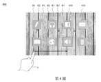
透過振動電路132以不同模式振動,當使用者之手指觸摸於顯示面板112、或滑動於顯示面板112上時,將會有不同的觸感,據此將能模擬出特殊的材質(例如:木紋、大理石紋等)。第4圖係本揭示內容之部份實施例中,顯示裝置100所顯示的螢幕畫面400之示意圖。在一實施例中,顯示裝置100係應用於車用面板。顯示面板112所顯示的螢幕畫面400中係包含了特殊材質的影像(如:木紋背景)。藉由前述振動電路132的不同模式,當使用者以手指F觸碰顯示裝置100、或者在螢幕畫面400上滑動出軌跡時,將會分別感受不同的觸感,如同接觸真實木板般。Through the vibration circuit 132 vibrating in different modes, when the user's finger touches the display panel 112 or slides on the display panel 112, there will be different tactile sensations, and a special material (for example, wood) can be simulated accordingly. pattern, marble pattern, etc.). FIG. 4 is a schematic diagram of a screen 400 displayed by the display device 100 in some embodiments of the present disclosure. In one embodiment, the display device 100 is applied to a vehicle panel. The screen 400 displayed on the display panel 112 includes images of special materials (eg, a wood grain background). With the aforementioned different modes of the vibration circuit 132 , when the user touches the display device 100 with his finger F or slides a track on the screen 400 , he will experience different tactile sensations, just like touching a real wooden board.

第5圖係本揭示內容之部份實施例的觸覺回饋方法的流程圖,包含步驟S501~S505。在步驟S501中,觸控偵測單元120偵測觸控電路121(觸控面板)與接觸物的觸控事件,而產生相應的偵測訊號。如第2圖所示之顯示裝置100之結構圖,「觸控事件」可為使用者以手指接觸觸控偵測單元120,使手指與觸控偵測單元120之間產生電位或電容變化,而形成偵測訊號。在其他實施例中,根據顯示裝置100的不同結構,「觸控事件」亦可為使用者距離觸控偵測單元120一段距離,以使觸控偵測單元120上之感測元件(如:電極)產生電性變化的狀態。FIG. 5 is a flowchart of a haptic feedback method according to some embodiments of the present disclosure, including steps S501 - S505 . In step S501, the touch detection unit 120 detects a touch event between the touch circuit 121 (touch panel) and the contact object, and generates a corresponding detection signal. As shown in the structural diagram of the display device 100 shown in FIG. 2 , the “touch event” is that the user touches the touch detection unit 120 with a finger, causing a potential or capacitance change between the finger and the touch detection unit 120 . A detection signal is formed. In other embodiments, according to different structures of the display device 100 , the “touch event” can also be a distance from the user to the touch detection unit 120 , so that the sensing elements on the touch detection unit 120 (eg: electrodes) to produce electrical changes.

在步驟S502中,觸控電路121將偵測訊號傳遞至偵測控制器122,以計算出接觸物的位移幅度。在部份實施例中,偵測訊號包含接觸物的座標位置。偵測控制器122判斷座標位置於一段偵測時間內的變化量,再根據變化量,計算出接觸物的位移速度及位移方向。在步驟S503中,偵測控制器122進一步判斷位移幅度是否大於位移門檻值。在其他部份實施例中,偵測控制器122可根據位移速度產生第一判斷訊號或第二判斷訊號,以改變振動電路132的振動頻率。例如:當位移速度越快時,振動頻率亦越高。In step S502, the touch circuit 121 transmits the detection signal to the detection controller 122 to calculate the displacement amplitude of the contact object. In some embodiments, the detection signal includes the coordinate position of the contact. The detection controller 122 judges the change amount of the coordinate position within a period of detection time, and then calculates the displacement speed and the displacement direction of the contact object according to the change amount. In step S503, the detection controller 122 further determines whether the displacement amplitude is greater than the displacement threshold. In other embodiments, the detection controller 122 can generate the first judgment signal or the second judgment signal according to the displacement speed, so as to change the vibration frequency of the vibration circuit 132 . For example: when the displacement speed is faster, the vibration frequency is also higher.

舉例而言,若在偵測時間中,觸控電路121所檢測到的偵測訊號中的座標位置係由(2,0)變化至(2.2,0),由於位移距離只有0.2,其位移幅度小於位移門檻值(如:1),故可視為接觸物處於靜止。反之,若在偵測時間中,若觸控電路121所檢測到的偵測訊號中的座標位置由(2,0)變化至(15,0),由於位移距離為13,其位移幅度大於門檻值,即可確認接觸物係在顯示面板112上滑動。For example, if during the detection time, the coordinate position in the detection signal detected by the touch circuit 121 changes from (2,0) to (2.2,0), since the displacement distance is only 0.2, the displacement amplitude is It is less than the displacement threshold value (eg: 1), so it can be considered that the contact object is at rest. Conversely, if during the detection time, if the coordinate position in the detection signal detected by the touch circuit 121 changes from (2,0) to (15,0), since the displacement distance is 13, the displacement amplitude is greater than the threshold value, it can be confirmed that the contact object is sliding on the display panel 112 .

在步驟S504中,當位移幅度小於位移門檻值時,偵測控制器122傳送第一判斷訊號至回饋控制器131,使回饋控制器131以第一頻率設定驅動訊號,並驅動振動電路132運作於第一模式。振動電路132將沿著第一方向振動。In step S504, when the displacement amplitude is less than the displacement threshold, the detection controller 122 sends a first determination signal to the feedback controller 131, so that the feedback controller 131 sets the driving signal at the first frequency, and drives the vibration circuit 132 to operate in first mode. The vibrating circuit 132 will vibrate in the first direction.

在步驟S505中,當位移幅度大於位移門檻值時,偵測控制器122傳送第二判斷訊號至回饋控制器131,使回饋控制器131根以第二頻率設定驅動訊號,並驅動振動電路132運作於第二模式。振動電路132將沿著第二方向振動。In step S505, when the displacement amplitude is greater than the displacement threshold, the detection controller 122 sends a second determination signal to the feedback controller 131, so that the feedback controller 131 sets the driving signal at the second frequency and drives the vibration circuit 132 to operate in the second mode. The vibrating circuit 132 will vibrate in the second direction.

第6A及6B圖為回饋控制器131輸出之驅動訊號(或振動電路132的振動波形)示意圖。如第6A圖所示,在部份實施例中,在回饋控制器131以第一頻率f1設定為驅動訊號的頻率時,驅動訊號的振幅會隨著時間變化。如第6B圖所示,在回饋控制器131以第二頻率f2設定為驅動訊號的頻率時,驅動訊號則呈現方波訊號之形式。6A and 6B are schematic diagrams of the driving signal (or the vibration waveform of the vibration circuit 132 ) output by the feedback controller 131 . As shown in FIG. 6A , in some embodiments, when the feedback controller 131 sets the first frequency f1 as the frequency of the driving signal, the amplitude of the driving signal changes with time. As shown in FIG. 6B , when the feedback controller 131 sets the second frequency f2 as the frequency of the driving signal, the driving signal is in the form of a square wave signal.

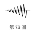
第7A及7B圖所示為根據本揭示內容之部份實施例中振動電路132於第一模式時的驅動訊號(或振動電路132的振動波形)示意圖。如第7A圖所示,驅動訊號之振幅可隨著時間變化起伏。如第7B圖所示,在其他實施例中,驅動訊號可為隨著時間逐漸加強。FIGS. 7A and 7B are schematic diagrams illustrating the driving signal (or the vibration waveform of the vibration circuit 132 ) when the vibration circuit 132 is in the first mode according to some embodiments of the present disclosure. As shown in FIG. 7A, the amplitude of the driving signal may fluctuate with time. As shown in FIG. 7B, in other embodiments, the driving signal may be gradually strengthened over time.

請搭配參閱第1、4、7A~7B圖所示,回饋控制器131可根據接觸物接觸力道或接觸位置,選擇性地改變驅動訊號的形式。例如:在一實施例中,顯示裝置100還包含壓力感測單元140。壓力感測單元140電性連接於觸控電路121及/或回饋控制器131,且用以感測接觸物接觸至顯示單元110或觸控偵測單元120時所施加的接觸力道。偵測控制器122或回饋控制器131能根據接觸力道來調整振動電路132的振動波形。振動波形的改變可包含頻率、振幅及波形(如:弦波或脈衝波)。舉例而言,在接觸力道大於預設值時,回饋控制器131調整驅動訊號,使振動電路的振動波形從第7A圖所示之波形變更為第7B圖之波形Please refer to Figures 1, 4, and 7A-7B. The feedback controller 131 can selectively change the form of the driving signal according to the contact force or the contact position of the contact object. For example, in one embodiment, the display device 100 further includes a pressure sensing unit 140 . The pressure sensing unit 140 is electrically connected to the touch circuit 121 and/or the feedback controller 131 , and is used for sensing the contact force exerted when the contact object touches the display unit 110 or the touch detection unit 120 . The detection controller 122 or the feedback controller 131 can adjust the vibration waveform of the vibration circuit 132 according to the contact force. Changes in vibration waveform can include frequency, amplitude, and waveform (eg, sine or pulse). For example, when the contact force is greater than the preset value, the feedback controller 131 adjusts the driving signal to change the vibration waveform of the vibration circuit from the waveform shown in FIG. 7A to the waveform shown in FIG. 7B

承上,在其他部份實施例中,當接觸物的靜止位置對應於使用者介面400上的圖標410(ICON)位置時,回饋控制器131係以第7A圖的波形產生驅動訊號。而當接觸物的靜止位置並未對應於使用者介面400上的圖標410時,回饋控制器131則改以第7B圖的波形產生驅動訊號。In other embodiments, when the static position of the contact object corresponds to the position of the icon 410 (ICON) on the user interface 400, the feedback controller 131 generates the driving signal with the waveform shown in FIG. 7A. When the resting position of the contact object does not correspond to the icon 410 on the user interface 400, the feedback controller 131 generates the driving signal with the waveform shown in FIG. 7B instead.

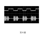
在部份實施例中,請參閱第1、4及8圖,顯示裝置100可根據接觸物的位置,選擇性地驅動振動電路132。顯示裝置100上設有多個第一區域R1及多個第二區域R2。該些第一區域R1及第二區域R2係對應於顯示面板112及觸控電路121。如第4圖所示,第一區域R1及第二區域R2於螢幕畫面400中交錯排列。當接觸物的位置對應於其中一個第一區域R1時,偵測控制器122輸出第一判斷訊號/第二判斷訊號至觸覺回饋單元130。反之,當接觸物的位置對應於其中一個第二區域R2時,偵測控制器122停止輸出第一判斷訊號/第二判斷訊號至觸覺回饋單元130。此時,回饋控制器131亦將停止驅動振動電路132。In some embodiments, please refer to FIGS. 1 , 4 and 8 , the display device 100 can selectively drive the vibration circuit 132 according to the position of the contact object. The display device 100 is provided with a plurality of first regions R1 and a plurality of second regions R2. The first regions R1 and the second regions R2 correspond to the display panel 112 and the touch circuit 121 . As shown in FIG. 4 , the first region R1 and the second region R2 are alternately arranged in the screen frame 400 . When the position of the contact object corresponds to one of the first regions R1 , the detection controller 122 outputs the first judgment signal/second judgment signal to the haptic feedback unit 130 . On the contrary, when the position of the contact object corresponds to one of the second regions R2 , the detection controller 122 stops outputting the first judgment signal/second judgment signal to the haptic feedback unit 130 . At this time, the feedback controller 131 will also stop driving the vibration circuit 132 .

第8圖所示為根據本揭示內容之部份實施例中振動電路132於第二模式時的驅動訊號示意圖。如圖所示,偵測控制器122係輸出第一判斷訊號/第二判斷訊號及區域偵測訊號至回饋控制器131。如第8圖的上方波形,區域偵測訊號可為高低電位組成之方波形式,用以代表接觸物對應於第一區域R1或第二區域R2。例如:當接觸物處於第一區域R1時,區域偵測訊號將處於致能準位(如:低電壓),此時偵測控制器122才會輸出驅動訊號至回饋控制器131。反之,當接觸物處於第二區域R2時,區域偵測訊號將處於禁能準位(如:高電壓),此時偵測控制器122將會停止輸出驅動訊號至回饋控制器131,確保振動電路132不會以第一模式或第二模式振動。FIG. 8 is a schematic diagram of driving signals of the vibration circuit 132 in the second mode according to some embodiments of the present disclosure. As shown in the figure, the detection controller 122 outputs the first judgment signal/second judgment signal and the area detection signal to the feedback controller 131 . As shown in the upper waveform in Fig. 8, the area detection signal may be in the form of a square wave composed of high and low potentials, representing that the contact object corresponds to the first area R1 or the second area R2. For example, when the contact object is in the first region R1, the region detection signal will be at an enabling level (eg, low voltage), and the detection controller 122 will only output the driving signal to the feedback controller 131 at this time. On the contrary, when the contact object is in the second area R2, the area detection signal will be at the disabled level (eg: high voltage), at this time, the detection controller 122 will stop outputting the driving signal to the feedback controller 131 to ensure vibration Circuit 132 does not vibrate in either the first mode or the second mode.

本揭示內容可使觸覺回饋單元130利用較少數量的振動源,來實現單點振動之效果(single point feedback),以及模擬紋理表面效果(texture feedback),形成多重觸覺之回饋,藉此將能改善顯示裝置100的互動真實感。The present disclosure enables the haptic feedback unit 130 to utilize a smaller number of vibration sources to achieve single point feedback and simulate texture feedback to form multiple haptic feedback. The interactive realism of the display device 100 is improved.

前述各實施例中的各項元件、方法步驟或技術特徵,係可相互結合,而不以本揭示內容中的文字描述順序或圖式呈現順序為限。The various elements, method steps or technical features in the foregoing embodiments can be combined with each other, and are not limited by the order of description in the text or the order of presentation of the drawings in the present disclosure.

雖然本揭示內容已以實施方式揭露如上,然其並非用以限定本揭示內容,任何熟習此技藝者,在不脫離本揭示內容之精神和範圍內,當可作各種更動與潤飾,因此本揭示內容之保護範圍當視後附之申請專利範圍所界定者為準。Although the present disclosure has been disclosed as above in embodiments, it is not intended to limit the present disclosure. Anyone skilled in the art can make various changes and modifications without departing from the spirit and scope of the present disclosure. Therefore, the present disclosure The scope of protection of the content shall be determined by the scope of the appended patent application.

100:顯示裝置100: Display device

110:顯示單元110: Display unit

111:顯示控制器111: Display Controller

112:顯示面板112: Display panel

120:觸控偵測單元120: Touch detection unit

121:觸控電路121: Touch circuit

122:偵測控制器122: detect controller

130:觸覺回饋單元130: Haptic feedback unit

131:回饋控制器131: Feedback Controller

132:振動電路132: Vibration Circuit

132a:雙軸向控制器132a: Dual Axial Controller

132b:觸覺振動板132b: Haptic Vibration Plate

140:壓力感測單元140: Pressure Sensing Unit

A:黏合劑A: Adhesive

fr:諧振頻率範圍fr: resonant frequency range

f1:第一頻率f1: the first frequency

f2:第二頻率f2: second frequency

D1:第一方向D1: first direction

D2:第二方向D2: Second direction

400:螢幕畫面400: screen image

410:圖標410: Icon

R1:第一區域R1: The first area

R2:第二區域R2: The second area

F:手指F: finger

S501-S505:步驟S501-S505: Steps

第1圖為根據本揭示內容之部份實施例之顯示裝置的示意圖。 第2圖為根據本揭示內容之部份實施例之顯示裝置的結構示意圖。 第3A~3C圖為根據本揭示內容之部份實施例之振動電路及其振動特性圖。 第4圖為根據本揭示內容之部份實施例之驅動訊號的示意圖。 第5圖為根據本揭示內容之部份實施例之觸覺回饋方法的步驟流程圖。 第6A及6B圖為根據本揭示內容之部份實施例之回饋控制器輸出之驅動訊號的示意圖。 第7A及7B圖為根據本揭示內容之部份實施例之振動電路於第一模式時的驅動訊號的示意圖。 第8圖所示為根據本揭示內容之部份實施例之振動電路於第二模式時的驅動訊號的示意圖。 FIG. 1 is a schematic diagram of a display device according to some embodiments of the present disclosure. FIG. 2 is a schematic structural diagram of a display device according to some embodiments of the present disclosure. FIGS. 3A-3C are diagrams of vibration circuits and vibration characteristics thereof according to some embodiments of the present disclosure. FIG. 4 is a schematic diagram of driving signals according to some embodiments of the present disclosure. FIG. 5 is a flow chart of steps of a haptic feedback method according to some embodiments of the present disclosure. 6A and 6B are schematic diagrams of driving signals output by a feedback controller according to some embodiments of the present disclosure. FIGS. 7A and 7B are schematic diagrams of driving signals of the vibrating circuit in the first mode according to some embodiments of the present disclosure. FIG. 8 is a schematic diagram illustrating the driving signal of the vibrating circuit in the second mode according to some embodiments of the present disclosure.

國內寄存資訊(請依寄存機構、日期、號碼順序註記) 無 國外寄存資訊(請依寄存國家、機構、日期、號碼順序註記) 無 Domestic storage information (please note in the order of storage institution, date and number) without Foreign deposit information (please note in the order of deposit country, institution, date and number) without

100:顯示裝置 100: Display device

110:顯示單元 110: Display unit

111:顯示控制器 111: Display Controller

112:顯示面板 112: Display panel

120:觸控偵測單元 120: Touch detection unit

121:觸控電路 121: Touch circuit

122:偵測控制器 122: detect controller

130:觸覺回饋單元 130: Haptic feedback unit

131:回饋控制器 131: Feedback Controller

132:振動電路 132: Vibration Circuit

140:壓力感測單元 140: Pressure Sensing Unit

Claims (16)

一種觸覺回饋方法,包含:透過一觸控電路,偵測一顯示裝置上的一接觸物,並產生對應之一偵測訊號;根據該偵測訊號,判斷該接觸物的一位移幅度;在該位移幅度小於一位移門檻值時,驅動一振動電路,使該振動電路以一第一模式振動;以及在該位移幅度大於一位移門檻值時,驅動該振動電路,使該振動電路以一第二模式振動;其中在該振動電路以該第一模式振動時,該振動電路係沿著一第一方向振動;在該振動電路以該第二模式振動時,該振動電路係沿著一第二方向振動,該第一方向係相異於該第二方向。 A tactile feedback method, comprising: detecting a contact object on a display device through a touch circuit, and generating a corresponding detection signal; judging a displacement amplitude of the contact object according to the detection signal; When the displacement amplitude is less than a displacement threshold value, drive a vibration circuit to make the vibration circuit vibrate in a first mode; and when the displacement amplitude is greater than a displacement threshold value, drive the vibration circuit to make the vibration circuit operate in a second mode Mode vibration; wherein when the vibrating circuit vibrates in the first mode, the vibrating circuit vibrates in a first direction; when the vibrating circuit vibrates in the second mode, the vibrating circuit vibrates in a second direction Vibration, the first direction is different from the second direction. 如請求項1所述之觸覺回饋方法,其中該第一方向及該第二方向互為正交。 The haptic feedback method according to claim 1, wherein the first direction and the second direction are orthogonal to each other. 如請求項1所述之觸覺回饋方法,其中在該振動電路以該第一模式振動時,該振動電路係以一第一頻率振動;在該振動電路以該第二模式振動時,該振動電路係以一第二頻率振動,該第一頻率係相異於該第二頻率。 The haptic feedback method of claim 1, wherein when the vibration circuit vibrates in the first mode, the vibration circuit vibrates at a first frequency; when the vibration circuit vibrates in the second mode, the vibration circuit vibrates It vibrates at a second frequency, and the first frequency is different from the second frequency. 如請求項1所述之觸覺回饋方法,還包含:判斷該接觸物與該顯示裝置的一接觸位置; 在該接觸位置對應於該顯示裝置上複數個第一區域的其中一個時,驅動該振動電路運作於該第一模式或該第二模式;以及在該接觸位置對應於該顯示裝置的複數個第二區域的其中一個時,停止驅動該振動電路。 The tactile feedback method according to claim 1, further comprising: judging a contact position between the contact object and the display device; When the contact position corresponds to one of a plurality of first regions on the display device, driving the vibration circuit to operate in the first mode or the second mode; and at the contact position corresponding to a plurality of first regions of the display device In one of the two regions, stop driving the vibration circuit. 如請求項4所述之觸覺回饋方法,其中該些第一區域及該些第二區域的位置係交錯排列。 The haptic feedback method according to claim 4, wherein the positions of the first regions and the second regions are staggered. 如請求項1所述之觸覺回饋方法,其中該偵測訊號包含該接觸物的一座標位置,判斷該接觸物之該位移幅度的方法包含:判斷該座標位置於一偵測時間內的一變化量;以及根據該變化量,計算該接觸物的一位移速度。 The tactile feedback method according to claim 1, wherein the detection signal includes a coordinate position of the contact object, and the method for judging the displacement magnitude of the contact object includes: judging a change of the coordinate position within a detection time and calculating a displacement velocity of the contact object according to the change amount. 如請求項6所述之觸覺回饋方法,還包含:根據該位移速度,調整該振動電路的一振動頻率。 The haptic feedback method according to claim 6, further comprising: adjusting a vibration frequency of the vibration circuit according to the displacement speed. 一種顯示裝置,包含:一顯示面板;一觸控偵測單元,用以檢測該顯示裝置與一接觸物的觸控事件,以取得一偵測訊號,其中該觸控偵測單元還用以根據該偵測訊號判斷該接觸物的一位移幅度;在該位移幅度小於一位移門檻值時,該觸控偵測單元產生一第一判斷 訊號;在該位移幅度大於該位移門檻值時,該觸控偵測單元產生一第二判斷訊號;以及一觸覺回饋單元,電性連接於該觸控偵測單元,其中該觸覺回饋單元用以接收該第一判斷訊號,以驅動一振動電路以一第一模式振動;該觸覺回饋單元還用以接收該第二判斷訊號,以驅動該振動電路以一第二模式振動;其中在該振動電路以該第一模式振動時,該振動電路係沿著一第一方向振動;在該振動電路以該第二模式振動時,該振動電路係沿著一第二方向振動,該第一方向係相異於該第二方向。 A display device, comprising: a display panel; a touch detection unit for detecting a touch event between the display device and a contact object to obtain a detection signal, wherein the touch detection unit is also used for The detection signal determines a displacement amplitude of the contact object; when the displacement amplitude is less than a displacement threshold, the touch detection unit generates a first determination signal; when the displacement amplitude is greater than the displacement threshold, the touch detection unit generates a second judgment signal; and a tactile feedback unit is electrically connected to the touch detection unit, wherein the tactile feedback unit is used for receiving the first judgment signal to drive a vibrating circuit to vibrate in a first mode; the haptic feedback unit is also used for receiving the second judgment signal to drive the vibrating circuit to vibrate in a second mode; wherein in the vibrating circuit When vibrating in the first mode, the vibrating circuit vibrates in a first direction; when the vibrating circuit vibrates in the second mode, the vibrating circuit vibrates in a second direction, and the first direction is phase-phase. different from the second direction. 如請求項8所述之顯示裝置,其中該第一方向及該第二方向互為正交。 The display device of claim 8, wherein the first direction and the second direction are orthogonal to each other. 如請求項8所述之顯示裝置,其中在該振動電路以該第一模式振動時,該振動電路係以一第一頻率振動;在該振動電路以該第二模式振動時,該振動電路係以一第二頻率振動,該第一頻率係相異於該第二頻率。 The display device of claim 8, wherein when the vibrating circuit vibrates in the first mode, the vibrating circuit vibrates at a first frequency; when the vibrating circuit vibrates in the second mode, the vibrating circuit vibrates Vibrates at a second frequency, the first frequency being different from the second frequency. 如請求項8所述之顯示裝置,其中該觸控偵測單元還用以判斷該接觸物與該顯示裝置的一接觸位置;在該接觸位置對應於該顯示面板上複數個第一區域的其中一個時,該觸控偵測單元傳送該第一判斷訊號或該第二判斷訊號至該觸覺回饋單元;在該觸控偵測單元對應於該顯 示面板的複數個第二區域的其中一個時,該觸控偵測單元停止傳送該第一判斷訊號或該第二判斷訊號至該觸覺回饋單元。 The display device according to claim 8, wherein the touch detection unit is further configured to determine a contact position between the contact object and the display device; the contact position corresponds to one of the plurality of first regions on the display panel one, the touch detection unit transmits the first judgment signal or the second judgment signal to the tactile feedback unit; when the touch detection unit corresponds to the display When one of the plurality of second regions of the display panel is selected, the touch detection unit stops transmitting the first judgment signal or the second judgment signal to the haptic feedback unit. 如請求項11所述之顯示裝置,其中該些第一區域及該些第二區域的位置係交錯排列。 The display device according to claim 11, wherein the positions of the first regions and the second regions are staggered. 如請求項8所述之顯示裝置,其中該偵測訊號包含一座標位置,該觸控偵測單元用以判斷該座標位置於一偵測時間內的一變化量,以根據該變化量,計算該接觸物的一位移速度。 The display device according to claim 8, wherein the detection signal includes a coordinate position, and the touch detection unit is used for judging a change of the coordinate position within a detection time, so as to calculate according to the change A displacement velocity of the contact. 如請求項13所述之顯示裝置,其中該觸控偵測單元係根據該位移速度調整該第一判斷訊號或該第二判斷訊號,以改變該振動電路之一振動頻率。 The display device of claim 13, wherein the touch detection unit adjusts the first judgment signal or the second judgment signal according to the displacement speed to change a vibration frequency of the vibration circuit. 如請求項8所述之顯示裝置,還包含:一壓力感測單元,用以偵測該接觸物與該顯示單元或該觸控偵測單元的一接觸力道。 The display device according to claim 8, further comprising: a pressure sensing unit for detecting a contact force between the contact object and the display unit or the touch detection unit. 如請求項15所述之顯示裝置,其中該觸控偵測單元或該觸覺回饋單元係根據該接觸力道調整該振動電路之一振動波形。The display device of claim 15, wherein the touch detection unit or the haptic feedback unit adjusts a vibration waveform of the vibration circuit according to the contact force.
TW109142119A 2020-11-30 2020-11-30 Display device and touch feedback method TWI756950B (en)

Priority Applications (3)

Application Number Priority Date Filing Date Title
TW109142119A TWI756950B (en) 2020-11-30 2020-11-30 Display device and touch feedback method
CN202110672664.2A CN113448436A (en) 2020-11-30 2021-06-17 Display device and tactile feedback method
US17/468,084 US20220171463A1 (en) 2020-11-30 2021-09-07 Display device and touch feedback method

Applications Claiming Priority (1)

Application Number Priority Date Filing Date Title
TW109142119A TWI756950B (en) 2020-11-30 2020-11-30 Display device and touch feedback method

Publications (2)

Publication Number Publication Date
TWI756950B true TWI756950B (en) 2022-03-01
TW202223604A TW202223604A (en) 2022-06-16

Family

ID=77811694

Family Applications (1)

Application Number Title Priority Date Filing Date
TW109142119A TWI756950B (en) 2020-11-30 2020-11-30 Display device and touch feedback method

Country Status (3)

Country Link
US (1) US20220171463A1 (en)
CN (1) CN113448436A (en)
TW (1) TWI756950B (en)

Families Citing this family (3)

* Cited by examiner, † Cited by third party
Publication number Priority date Publication date Assignee Title
JP2023151407A (en) * 2022-03-31 2023-10-16 シャープディスプレイテクノロジー株式会社 Touch panel system, display device, and touch panel control method
US12254135B2 (en) * 2023-03-28 2025-03-18 Sensel, Inc. Simulation of a physical interface utilizing touch tracking, force sensing, and haptic feedback
CN116704891A (en) * 2023-05-26 2023-09-05 瑞声开泰声学科技(上海)有限公司 Vehicle-mounted large screen module with vibration sense

Citations (5)

* Cited by examiner, † Cited by third party
Publication number Priority date Publication date Assignee Title
US20050110769A1 (en) * 2003-11-26 2005-05-26 Dacosta Henry Systems and methods for adaptive interpretation of input from a touch-sensitive input device
TW201108054A (en) * 2009-08-21 2011-03-01 J Touch Corp Light permeable vibrating component and module thereof
US20110316798A1 (en) * 2010-02-26 2011-12-29 Warren Jackson Tactile Display for Providing Touch Feedback
TW201642943A (en) * 2015-03-20 2016-12-16 新力電腦娛樂股份有限公司 Dynamic gloves to convey sense of touch and movement for virtual objects in HMD rendered environments
TW202004475A (en) * 2018-06-01 2020-01-16 美商谷歌有限責任公司 Trackpad with capacitive force sensing and haptic feedback

Family Cites Families (3)

* Cited by examiner, † Cited by third party
Publication number Priority date Publication date Assignee Title
KR20140047897A (en) * 2012-10-15 2014-04-23 삼성전자주식회사 Method for providing for touch effect and an electronic device thereof
JP6731866B2 (en) * 2017-02-06 2020-07-29 株式会社デンソーテン Control device, input system and control method
FR3066030B1 (en) * 2017-05-02 2019-07-05 Centre National De La Recherche Scientifique METHOD AND DEVICE FOR GENERATING TOUCH PATTERNS

Patent Citations (5)

* Cited by examiner, † Cited by third party
Publication number Priority date Publication date Assignee Title
US20050110769A1 (en) * 2003-11-26 2005-05-26 Dacosta Henry Systems and methods for adaptive interpretation of input from a touch-sensitive input device
TW201108054A (en) * 2009-08-21 2011-03-01 J Touch Corp Light permeable vibrating component and module thereof
US20110316798A1 (en) * 2010-02-26 2011-12-29 Warren Jackson Tactile Display for Providing Touch Feedback
TW201642943A (en) * 2015-03-20 2016-12-16 新力電腦娛樂股份有限公司 Dynamic gloves to convey sense of touch and movement for virtual objects in HMD rendered environments
TW202004475A (en) * 2018-06-01 2020-01-16 美商谷歌有限責任公司 Trackpad with capacitive force sensing and haptic feedback

Also Published As

Publication number Publication date
US20220171463A1 (en) 2022-06-02
CN113448436A (en) 2021-09-28
TW202223604A (en) 2022-06-16

Similar Documents

Publication Publication Date Title
CN105718106B (en) Touch-sensitive device and display device including the same
JP4803105B2 (en) Electronics
US9857872B2 (en) Multi-touch display screen with localized tactile feedback
JP4997335B2 (en) Portable device with touch screen and digital tactile pixels
JP4229098B2 (en) Touch panel display device, electronic device including touch panel display device, and camera including touch panel display device
TWI756950B (en) Display device and touch feedback method
KR20140109292A (en) Haptic device with linear resonant actuator
TWI644242B (en) Touch device, electronic device applying the same, and driving method of touch feedback
CN101882023B (en) Touch display device with vibrating function and vibrating type touch pad
US20120038568A1 (en) Touch Sensitive Device
JP2015121983A (en) Tactile presentation device
JPWO2015121955A1 (en) Electronic device, input device, and drive control method
US20060097996A1 (en) Input device
JP2019067379A (en) Display device equipped with force sensor and method of manufacturing the same
KR20210018703A (en) Display device
JP2018128741A (en) Control device, input system, and control method
TWI397845B (en) Touch sensing display having vibration function and vibration type touch sensing board
KR20160069752A (en) Haptic display device and method for driving the same
JP2008123429A (en) Touch panel display device, electronic device, and game device
WO2020110737A1 (en) Electronic device
JP2018128742A (en) Control device, input system, and control method
KR101181676B1 (en) Touch panel
KR20160075019A (en) Display device
JP2006209570A (en) Input device
TWI767727B (en) Haptic plate system and method for forming the same