TWI749894B - Head mounted display - Google Patents
Head mounted display Download PDFInfo
- Publication number
- TWI749894B TWI749894B TW109141048A TW109141048A TWI749894B TW I749894 B TWI749894 B TW I749894B TW 109141048 A TW109141048 A TW 109141048A TW 109141048 A TW109141048 A TW 109141048A TW I749894 B TWI749894 B TW I749894B
- Authority
- TW
- Taiwan
- Prior art keywords
- display
- image
- area
- head
- target area
- Prior art date
Links
Images


Classifications
-
- G—PHYSICS
- G02—OPTICS
- G02B—OPTICAL ELEMENTS, SYSTEMS OR APPARATUS
- G02B27/00—Optical systems or apparatus not provided for by any of the groups G02B1/00 - G02B26/00, G02B30/00
- G02B27/01—Head-up displays
- G02B27/017—Head mounted
- G02B27/0172—Head mounted characterised by optical features
-
- G—PHYSICS
- G06—COMPUTING OR CALCULATING; COUNTING
- G06F—ELECTRIC DIGITAL DATA PROCESSING
- G06F3/00—Input arrangements for transferring data to be processed into a form capable of being handled by the computer; Output arrangements for transferring data from processing unit to output unit, e.g. interface arrangements
- G06F3/01—Input arrangements or combined input and output arrangements for interaction between user and computer
- G06F3/011—Arrangements for interaction with the human body, e.g. for user immersion in virtual reality
- G06F3/013—Eye tracking input arrangements
-
- G—PHYSICS
- G02—OPTICS
- G02B—OPTICAL ELEMENTS, SYSTEMS OR APPARATUS
- G02B27/00—Optical systems or apparatus not provided for by any of the groups G02B1/00 - G02B26/00, G02B30/00
- G02B27/0025—Optical systems or apparatus not provided for by any of the groups G02B1/00 - G02B26/00, G02B30/00 for optical correction, e.g. distorsion, aberration
- G02B27/0037—Optical systems or apparatus not provided for by any of the groups G02B1/00 - G02B26/00, G02B30/00 for optical correction, e.g. distorsion, aberration with diffracting elements
-
- G—PHYSICS
- G02—OPTICS
- G02B—OPTICAL ELEMENTS, SYSTEMS OR APPARATUS
- G02B27/00—Optical systems or apparatus not provided for by any of the groups G02B1/00 - G02B26/00, G02B30/00
- G02B27/0081—Optical systems or apparatus not provided for by any of the groups G02B1/00 - G02B26/00, G02B30/00 with means for altering, e.g. enlarging, the entrance or exit pupil
-
- G—PHYSICS
- G02—OPTICS
- G02B—OPTICAL ELEMENTS, SYSTEMS OR APPARATUS
- G02B27/00—Optical systems or apparatus not provided for by any of the groups G02B1/00 - G02B26/00, G02B30/00
- G02B27/0093—Optical systems or apparatus not provided for by any of the groups G02B1/00 - G02B26/00, G02B30/00 with means for monitoring data relating to the user, e.g. head-tracking, eye-tracking
-
- G—PHYSICS
- G02—OPTICS
- G02B—OPTICAL ELEMENTS, SYSTEMS OR APPARATUS
- G02B27/00—Optical systems or apparatus not provided for by any of the groups G02B1/00 - G02B26/00, G02B30/00
- G02B27/01—Head-up displays
- G02B27/0179—Display position adjusting means not related to the information to be displayed
-
- G—PHYSICS
- G09—EDUCATION; CRYPTOGRAPHY; DISPLAY; ADVERTISING; SEALS
- G09G—ARRANGEMENTS OR CIRCUITS FOR CONTROL OF INDICATING DEVICES USING STATIC MEANS TO PRESENT VARIABLE INFORMATION
- G09G3/00—Control arrangements or circuits, of interest only in connection with visual indicators other than cathode-ray tubes
- G09G3/001—Control arrangements or circuits, of interest only in connection with visual indicators other than cathode-ray tubes using specific devices not provided for in groups G09G3/02 - G09G3/36, e.g. using an intermediate record carrier such as a film slide; Projection systems; Display of non-alphanumerical information, solely or in combination with alphanumerical information, e.g. digital display on projected diapositive as background
-
- H—ELECTRICITY
- H04—ELECTRIC COMMUNICATION TECHNIQUE
- H04N—PICTORIAL COMMUNICATION, e.g. TELEVISION
- H04N23/00—Cameras or camera modules comprising electronic image sensors; Control thereof
- H04N23/70—Circuitry for compensating brightness variation in the scene
- H04N23/72—Combination of two or more compensation controls
-
- H—ELECTRICITY
- H04—ELECTRIC COMMUNICATION TECHNIQUE
- H04N—PICTORIAL COMMUNICATION, e.g. TELEVISION
- H04N23/00—Cameras or camera modules comprising electronic image sensors; Control thereof
- H04N23/70—Circuitry for compensating brightness variation in the scene
- H04N23/74—Circuitry for compensating brightness variation in the scene by influencing the scene brightness using illuminating means
-
- H—ELECTRICITY
- H04—ELECTRIC COMMUNICATION TECHNIQUE
- H04N—PICTORIAL COMMUNICATION, e.g. TELEVISION
- H04N9/00—Details of colour television systems
- H04N9/12—Picture reproducers
- H04N9/31—Projection devices for colour picture display, e.g. using electronic spatial light modulators [ESLM]
- H04N9/3141—Constructional details thereof
- H04N9/3173—Constructional details thereof wherein the projection device is specially adapted for enhanced portability
- H04N9/3176—Constructional details thereof wherein the projection device is specially adapted for enhanced portability wherein the projection device is incorporated in a camera
-
- H—ELECTRICITY
- H04—ELECTRIC COMMUNICATION TECHNIQUE
- H04N—PICTORIAL COMMUNICATION, e.g. TELEVISION
- H04N9/00—Details of colour television systems
- H04N9/12—Picture reproducers
- H04N9/31—Projection devices for colour picture display, e.g. using electronic spatial light modulators [ESLM]
- H04N9/3191—Testing thereof
- H04N9/3194—Testing thereof including sensor feedback
-
- G—PHYSICS
- G02—OPTICS
- G02B—OPTICAL ELEMENTS, SYSTEMS OR APPARATUS
- G02B27/00—Optical systems or apparatus not provided for by any of the groups G02B1/00 - G02B26/00, G02B30/00
- G02B27/01—Head-up displays
- G02B27/0179—Display position adjusting means not related to the information to be displayed
- G02B2027/0187—Display position adjusting means not related to the information to be displayed slaved to motion of at least a part of the body of the user, e.g. head, eye
-
- G—PHYSICS
- G09—EDUCATION; CRYPTOGRAPHY; DISPLAY; ADVERTISING; SEALS
- G09G—ARRANGEMENTS OR CIRCUITS FOR CONTROL OF INDICATING DEVICES USING STATIC MEANS TO PRESENT VARIABLE INFORMATION
- G09G2320/00—Control of display operating conditions
- G09G2320/06—Adjustment of display parameters
- G09G2320/0686—Adjustment of display parameters with two or more screen areas displaying information with different brightness or colours
-
- G—PHYSICS
- G09—EDUCATION; CRYPTOGRAPHY; DISPLAY; ADVERTISING; SEALS
- G09G—ARRANGEMENTS OR CIRCUITS FOR CONTROL OF INDICATING DEVICES USING STATIC MEANS TO PRESENT VARIABLE INFORMATION
- G09G2354/00—Aspects of interface with display user
Landscapes
- Physics & Mathematics (AREA)
- Engineering & Computer Science (AREA)
- General Physics & Mathematics (AREA)
- Optics & Photonics (AREA)
- Multimedia (AREA)
- Signal Processing (AREA)
- Theoretical Computer Science (AREA)
- General Engineering & Computer Science (AREA)
- Computer Hardware Design (AREA)
- Human Computer Interaction (AREA)
Abstract
Description
本發明是有關於一種頭戴式顯示器,且特別是有關於一種可提升眼球追蹤動作精確度的頭戴式顯示器。The present invention relates to a head-mounted display, and particularly relates to a head-mounted display that can improve the accuracy of eye tracking movements.
在習知技術中,頭戴式顯示器中常透過設置光學元件來使用來顯示畫面的影像光束可傳送至使用者的眼睛。然而,透過設置這類的光學元件,常會使用以執行眼球追蹤動作的紅外線光束,也發生傳輸路徑的偏折動作,造成紅外線照相機無法有效的擷取到使用者眼球影像,並降低眼球追蹤的精確度。In the prior art, the image light beam used to display the screen by installing optical elements in the head-mounted display can be transmitted to the user's eyes. However, by installing such optical components, the infrared beams that are often used to perform eye-tracking actions are also deflected in the transmission path, causing the infrared camera to be unable to effectively capture the user’s eye image and reducing the accuracy of eye-tracking. Spend.
本發明提供一種頭戴式顯示器,可提升眼球追蹤動作的精確度。The invention provides a head-mounted display, which can improve the accuracy of eye-tracking actions.
本發明的頭戴式顯示器包括至少一顯示器、第一影像擷取器、光束產生器以及光學補償元件。顯示器具有開口區域,顯示器產生至少一影像光束。第一影像擷取器對應開口區域,與顯示器重疊設置,用以通過開口區域,擷取目標區上的目標區影像。光束產生器用以投射至少一光束至目標區。目標區並反射光束以產生至少一反射光束。光學補償元件設置在顯示器與目標區間。光學補償元件用以轉換影像光束的傳送方向,並使反射光束直接透射至第一影像擷取器。The head-mounted display of the present invention includes at least one display, a first image capturer, a beam generator, and an optical compensation element. The display has an open area, and the display generates at least one image beam. The first image capturer corresponds to the opening area and is arranged to overlap the display, and is used to capture the target area image on the target area through the opening area. The beam generator is used for projecting at least one beam to the target area. The target area reflects the light beam to generate at least one reflected light beam. The optical compensation element is arranged between the display and the target. The optical compensation element is used for converting the transmission direction of the image beam, and directly transmits the reflected beam to the first image capturer.
基於上述,本發明實施例的頭戴式顯示器透過設置光學補償元件,使影像光束可以轉換為準直光束以傳送至使用者眼球,並使目標區的眼球的影像,可以直接穿透光學補償元件以傳送至影像擷取器上。如此一來,在兼顧顯示影像的視覺品質的前提下,影像擷取器仍可準確的獲得使用者的眼球的影像,維持眼球追蹤動作的準確度。Based on the above, the head-mounted display of the embodiment of the present invention is provided with an optical compensation element, so that the image beam can be converted into a collimated beam for transmission to the user's eyeball, and the image of the eyeball in the target area can directly penetrate the optical compensation element To send to the image capturer. In this way, under the premise of taking into account the visual quality of the displayed image, the image capturer can still accurately obtain the image of the user's eyeball and maintain the accuracy of the eyeball tracking action.
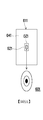
請參照圖1,圖1繪示本發明一實施例的頭戴式顯示器的示意圖。頭戴式顯示器100包括顯示器110、影像擷取器120、光束產生器130-1、130-2、光學補償元件140以及透鏡組150。在本實施例中,顯示器110用以產生影像光束ILB。顯示器110並具有一開口區域OZ1。影像擷取器120則對應開口區域OZ1,與顯示器110相互重疊設置。顯示器110並用以通過開口區域OZ1以擷取目標區TG上的目標區影像。在本實施例中,目標區TG可以為使用者眼球的區域,而目標區TG上的目標區影像可以為使用者眼球的影像。Please refer to FIG. 1. FIG. 1 is a schematic diagram of a head-mounted display according to an embodiment of the present invention. The head-mounted
在本實施例中,光束產生器130-1、103-2可以分別設置在透鏡組150的兩個側邊。光束產生器130-1、103-2分別產生光束LB1、LB2,並傳送光束LB1、LB2至目標區TG。目標區TG並反射光束LB1、LB2以分別產生反射光束RLB1、RLB2,並使反射光束RLB1、RLB2被傳送至光學補償元件140。In this embodiment, the beam generators 130-1 and 103-2 may be respectively arranged on two sides of the
在本實施例中,光束產生器130-1、103-2可以為紅外線發射器,且光束產生器130-1、103-2的數量可以為一個或是多個,沒有固定的限制。此外,影像擷取器120則可以為一照相機,例如為可感測出紅外線影像的紅外線照相機。In this embodiment, the beam generators 130-1 and 103-2 can be infrared emitters, and the number of beam generators 130-1 and 103-2 can be one or more, and there is no fixed limit. In addition, the image capturer 120 can be a camera, for example, an infrared camera that can sense infrared images.
此外,光學補償元件140設置在顯示器110與目標區TG間。光學補償元件140用以轉換影像光束ILB的傳送方向,並產生為準直光束的影像光束ILB’來傳送至透鏡組150。在另一方面,光學補償元件140並可使由目標區TG傳送至的反射光束RLB1以及RLB2在不變更傳送方向的前提下,直接透射至影像擷取器120。如此一來,影像擷取器120可以有效擷取到目標區影像,維持眼球追蹤動作的準確度。In addition, the
在此請注意,在本發明實施例中,光學補償元件140可以為分光繞射元件(Diffractive optics element)。分光繞射元件可以能夠依據入射光波的頻段,來決定是否改變入射光波的波前,以改變了入射光的路徑。在本實施例中,光學補償元件140可改變影像光束ILB的傳送路徑,但不改變反射光束RLB1以及RLB2的傳送路徑。Please note here that, in the embodiment of the present invention, the
附帶一提,在本實施例中,光學補償元件140與透鏡組150間的距離,大於光學補償元件140與顯示器110間的距離。Incidentally, in this embodiment, the distance between the
以下請參照圖2,圖2繪示本發明另一實施例的頭戴式顯示器的示意圖。頭戴式顯示器200包括顯示器210、影像擷取器220、光束產生器230-1、230-2、光學補償元件240以及透鏡組250。顯示器210用以產生影像光束ILB。光學補償元件240用以改變影像光束ILB的傳輸路徑,並產生影像光束ILB’以傳送至目標區TG。目標區TG上產生的反射光束RLB並直接通過光學補償元件240以傳送至顯示器210的開口區域OZ1中的影像擷取器220。如此一來,影像擷取器220可有效擷取到目標區影像。Please refer to FIG. 2 below. FIG. 2 is a schematic diagram of a head-mounted display according to another embodiment of the present invention. The head-mounted
與前述實施例不相同的,本實施例中,光學補償元件240與透鏡組250間的距離,小於光學補償元件240與顯示器210間的距離。Different from the foregoing embodiment, in this embodiment, the distance between the
以下請參照圖3A以及圖3B,圖3A以及圖3B繪示本發明另一實施例的頭戴式顯示器及其動作示意圖。在圖3A中,頭戴式顯示器300包括顯示器310、影像擷取器320、光束產生器330、光學補償元件340、透鏡組350以及控制器370。顯示器310具有開口區域,影像擷取器320設置在開口區域,並與顯示器310重疊配置。在本實施例中,顯示器310可區分為第一顯示區域DA1以及第二顯示區域DA2。其中第二顯示區域DA2相對於第一顯示區域DA1較接近開口區域。光學補償元件340包括第一部分341以及第二部分342。Please refer to FIGS. 3A and 3B below. FIGS. 3A and 3B illustrate a head-mounted display and a schematic diagram of its operation according to another embodiment of the present invention. In FIG. 3A, the head-mounted
在本實施例中,光學補償元件341、342為動態折射光學(Dynamic refractive optics)元件,並可依據為電氣信號的控制信號CTRL來改變形狀。其中在本實施例中,在第一時間區間中,光學補償元件340的第一部分341、第二部分342朝向透鏡組350的第一表面可依據控制信號CTRL被調整為曲面,而光學補償元件340的第一部分341、第二部分342朝向顯示器310的第二表面則可維持為平面。控制信號CTRL由控制器370來提供。In this embodiment, the
在此同時,顯示器310的第二顯示區域DA2所產生的影像光束ILB2的亮度,為顯示器310的第一顯示區域DA1所產生的影像光束ILB1的亮度的兩倍。此時,光學補償元件340的第一部分341、第二部分342依據第一表面的曲度,來針對影像光束ILB1以及影像光束ILB2進行傳輸路徑的調整,並將調整後的影像光束ILB1’、ILB2’傳送至透鏡組350。At the same time, the brightness of the image light beam ILB2 generated by the second display area DA2 of the
值得注意的,在本實施例中,在第一時間區間中,光束產生器330以及影像擷取器320被關閉而不執行動作。It is worth noting that in this embodiment, in the first time interval, the
接著請參照圖3B,在第二時間區間中,光學補償元件341、342朝向透鏡組350的第一表面可依據控制信號CTRL被調整為平面,而光學補償元件340的第一部分341、第二部分342朝向顯示器310的第二表面則維持為平面。在此同時,顯示器310的第二顯示區域DA2所產生的影像光束ILB2的亮度與顯示器310的第一顯示區域DA1所產生的影像光束ILB1的亮度相同。並且,光束產生器330開始發送光束LB至目標區TG。目標區TG可依據光束LB產生反射光束RLB。反射光束RLB可直接通過光學補償元件340的第一部分341、第二部分342相互連接的區域ZA,以傳輸至影像擷取器320。3B, in the second time interval, the first surface of the
在此請注意,在第二時間區間中,基於光學補償元件340的第一部分341、第二部分342的截面被調整為矩形的形狀,因此在光學補償元件340的第一部分341、第二部分342中,對應顯示器310的開口區域的區域ZA不會有影像光束ILB1、ILB2通過。而反射光束RLB可不受干擾的通過區域ZA以傳送至影像擷取器320。Please note here that in the second time interval, the cross-sections of the
此外,在第二時間區間中,影像擷取器320被啟動以擷取目標區TG上的目標區影像。其中透過目標區影像上,反射光束RLB所產生的光點位置,可有效執行眼球追蹤動作。In addition, in the second time interval, the
以下請同步參照圖3A至圖3C,圖3C繪示本發明圖3A、圖3B實施例的頭戴式顯示器的動作波形示意圖。頭戴式顯示器300的動作可以依據同步信號SYNC來執行。同步信號SYNC的每一周期可定義出每一圖像框週期(frame period)。在一圖像框週期FR中的第一時間區間T1中,用以控制光學補償元件340的控制信號CTRL的電壓值被拉高,並使光學補償元件340發生形變。在此同時,第二顯示區域DA2所產生的影像光束ILB2的亮度為第一顯示區域DA1所產生的影像光束ILB1的亮度的兩倍。接著,在第二時間區間T2中,控制信號CTRL的電壓值被拉低,光學補償元件340的截面恢復為矩形。同時,第二顯示區域DA2所產生的影像光束ILB2的亮度變更為與第一顯示區域DA1所產生的影像光束ILB1的亮度相同。另外,影像擷取器320、光束產生器330依據信號EYET以啟動,並執行眼球追蹤的動作。同步信號SYNC、信號EYET也可由控制器370來產生。Please refer to FIGS. 3A to 3C synchronously below. FIG. 3C is a schematic diagram of the action waveforms of the head-mounted display of the embodiments of FIGS. 3A and 3B of the present invention. The actions of the head mounted
值得一提的,在第一時間區間T1中,透過提升影像光束ILB2,可以補償在第二時間區間T2中,對應區域ZA的位置沒有提供影像光束所可能造成的亮度差異,並可有效維持顯示影像的品質。It is worth mentioning that in the first time interval T1, by raising the image light beam ILB2, it is possible to compensate for the possible brightness difference caused by the position of the corresponding area ZA not providing the image light beam in the second time interval T2, and the display can be effectively maintained. The quality of the image.
在本實施例中,圖像框週期FR可對應120赫茲的頻率。In this embodiment, the image frame period FR may correspond to a frequency of 120 Hz.
本發明實施例中的控制器370可以為具運算能力的處理器。或者,控制器370可以是透過硬體描述語言(Hardware Description Language, HDL)或是其他任意本領域具通常知識者所熟知的數位電路的設計方式來進行設計,並透過現場可程式邏輯門陣列(Field Programmable Gate Array, FPGA)、複雜可程式邏輯裝置(Complex Programmable Logic Device, CPLD)或是特殊應用積體電路(Application-specific Integrated Circuit, ASIC)的方式來實現的硬體電路。The
以下請同步參照圖4A至圖4C,圖4A至圖4C繪示本發明實施例的頭戴式顯示器的另一動作方式的示意圖。本實施方式的頭戴式顯示器的硬體架構與圖3A中的頭戴式顯示器300相同,在此不多贅述。其中,在圖4A、圖4C中,基於同步信號SYNC,在一圖像框週期FR的第一時間區間T1中,光學補償元件340的第一部分341、第二部分342依據被拉高的控制信號CTRL產生形變。在此同時,顯示器310的第一顯示區域DA1不發送影像光束ILB1;顯示器310的第二顯示區域DA2發送影像光束ILB2。光學補償元件340的第二部分342調整影像光束ILB2的傳輸路徑,並將影像光束ILB2’傳送至目標區TG。Hereinafter, please refer to FIGS. 4A to 4C simultaneously. FIGS. 4A to 4C are schematic diagrams of another operation mode of the head-mounted display according to an embodiment of the present invention. The hardware architecture of the head-mounted display of this embodiment is the same as that of the head-mounted
另外,在圖4B、圖4C中,在第二時間區間T2,光學補償元件340的第一部分341、第二部分342的截面依據被拉低的控制信號CTRL恢復為矩形。顯示器310的第一顯示區域DA1與第二顯示區域DA2分別發送相同亮度的影像光束ILB1以及影像光束ILB2。In addition, in FIGS. 4B and 4C, in the second time interval T2, the cross-sections of the
同時,在第二時間區間T2,影像擷取器320、光束產生器330可依據信號EYET以啟動,並執行眼球追蹤的動作。At the same time, in the second time interval T2, the
以下請同步參照圖5A至圖5C,圖5A至圖5C繪示本發明實施例的頭戴式顯示器的另一動作方式的示意圖。本實施方式的頭戴式顯示器的硬體架構與圖3A中的頭戴式顯示器300相同,在此不多贅述。其中,在圖5A、圖5C中,基於同步信號SYNC,在一圖像框週期FR的第一時間區間T1中,光學補償元件340的第一部分341、第二部分342依據被拉高的控制信號CTRL產生形變。在此同時,顯示器310的第一顯示區域DA1與第二顯示區域DA2發送具有相同亮度的影像光束ILB1、ILB2。Hereinafter, please refer to FIGS. 5A to 5C simultaneously. FIGS. 5A to 5C are schematic diagrams of another action mode of the head-mounted display according to an embodiment of the present invention. The hardware architecture of the head-mounted display of this embodiment is the same as that of the head-mounted
另外,在圖4B、圖4C中,在第二時間區間T2,光學補償元件340的第一部分341、第二部分342的截面依據被拉低的控制信號CTRL恢復為矩形。顯示器310的第一顯示區域DA1與第二顯示區域DA2停止發送影像光束ILB1、ILB2。In addition, in FIGS. 4B and 4C, in the second time interval T2, the cross-sections of the
同時,在第二時間區間T2,影像擷取器320、光束產生器330可依據信號EYET以啟動,並執行眼球追蹤的動作。At the same time, in the second time interval T2, the
以下請參照圖6A至圖6H,圖6A至圖6H分別繪示本發明實施例的頭戴式顯示器的顯示器、影像擷取器、光學補償元件的多個配置方式的示意圖。在圖6A中,頭戴式顯示器601的顯示器611配置在光學補償元件641的後方,並具有開口區域OZ1。影像擷取器621設置在開口區域OZ1中。在圖6B中,頭戴式顯示器602具有顯示器612-1以及612-2以配置在光學補償元件642的後方。顯示器612-1以及612-2間具有一間隔區域BZ1。影像擷取器622可設置在間隔區域BZ1中。在本實施方式中,間隔區域BZ1等效於顯示器中的開口區域。在圖6C中,頭戴式顯示器603具有顯示器613-1以及613-2以配置在光學補償元件643的後方。顯示器613-1以及613-2間並具有一間隔區域BZ2。其中,間隔區域BZ2與前述實施方式中的間隔區域BZ1的走向是不相同的(例如相互正交)。影像擷取器623可設置在間隔區域BZ2中。在圖6D中,頭戴式顯示器604具有顯示器614-1~614-4以2X2的方式配置在光學補償元件644的後方。顯示器614-1~614-4間並形成十字的間隔區域BZ3,影像擷取器624可設置在十字的間隔區域BZ3的中心位置。Hereinafter, please refer to FIGS. 6A to 6H. FIGS. 6A to 6H respectively show schematic diagrams of multiple configurations of the display, image capture device, and optical compensation element of the head-mounted display according to an embodiment of the present invention. In FIG. 6A, the
在圖6E中,頭戴式顯示器605的顯示器615配置在光學補償元件645的後方。顯示器615具有開口區域OZ1以及輔助開口區域OZ2、OZ3。頭戴式顯示器605包括影像擷取器625以及輔助影像擷取器625-1、625-2。影像擷取器625以及輔助影像擷取器625-1、625-2分別設置在開口區域OZ1以及輔助開口區域OZ2、OZ3中。In FIG. 6E, the
在圖6F中,頭戴式顯示器606的顯示器616-1、616-2配置在光學補償元件646的後方。顯示器616-1、616-2相互水平排列,並形成間隔區域BZ4。頭戴式顯示器606並包括影像擷取器626以及輔助影像擷取器626-1、626-2。其中,輔助影像擷取器626-1、影像擷取器626以及輔助影像擷取器626-2可依序排列在間隔區域BZ4中。In FIG. 6F, the displays 616-1 and 616-2 of the head mounted
在圖6G中,頭戴式顯示器607的顯示器617-1、617-2配置在光學補償元件647的後方。顯示器617-1、617-2相互垂直排列,並形成間隔區域BZ5。頭戴式顯示器607並包括影像擷取器627以及輔助影像擷取器627-1、627-2。其中,輔助影像擷取器627-1、影像擷取器627以及輔助影像擷取器627-2可依序排列在間隔區域BZ5中。In FIG. 6G, the displays 617-1 and 617-2 of the head-mounted
在圖6H中,頭戴式顯示器608的顯示器618-1~618-4以2X2的形式配置在光學補償元件648的後方。顯示器618-1~618-4間並形成十字形的間隔區域BZ6。頭戴式顯示器608並包括影像擷取器628以及輔助影像擷取器628-1~628-4。其中,影像擷取器628以及輔助影像擷取器628-1~628-4分布設置在間隔區域BZ6中。細節上,影像擷取器628設置在間隔區域BZ6的中心區域,輔助影像擷取器628-1、628-2相互水平設置,輔助影像擷取器628-3、628-4則相互垂直設置。In FIG. 6H, the displays 618-1 to 618-4 of the head mounted
以下請參照圖7,圖7繪示本發明另一實施例的頭戴式顯示器的示意圖。在圖7中,頭戴式顯示器700的顯示器710延一方向可具有多個開口區域(例如3個或大於3的奇數個),並用以設置多個影像擷取器721~723。影像擷取器722可以設置在對應至光學補償元件740的中心位置,並正對目標區。影像擷取器721、723則可設置在影像擷取器722的兩側。影像擷取器721、723可以做為輔助影像擷取器。Please refer to FIG. 7 below. FIG. 7 is a schematic diagram of a head-mounted display according to another embodiment of the present invention. In FIG. 7, the
在本實施例中,依據不同角度的影像擷取器721~723所擷取的目標區影像,可以計算出使用者眼球的曲度,以優化眼球追蹤動作的功效。In this embodiment, the curvature of the user's eyeball can be calculated based on the images of the target area captured by the
以下請參照圖8,圖8繪示本發明另一實施例的頭戴式顯示器的示意圖。在圖8中,頭戴式顯示器800的顯示器810延一方向可具有多個開口區域(例如2個或大於2的奇數個),並用以設置多個影像擷取器821~822。在本實施例中,對應至光學補償元件840的中心位置可不需設置影像擷取器。影像擷取器821、822可設置在對應目標區TG的兩個側邊。影像擷取器821、822可以擷取到不同角度的目標區影像,可作為計算出使用者眼球的曲度的依據。Please refer to FIG. 8 below. FIG. 8 is a schematic diagram of a head-mounted display according to another embodiment of the present invention. In FIG. 8, the
綜上所述,本發明提供光學補償元件,使用以顯示的影像光束以及作為眼球追蹤依據的反射光束,在不相互干擾的前提下,分別傳送至目標區以及影像擷取器。如此一來,在不減低顯示效果的條件下,頭戴式顯示器仍可執行具有高精確度的眼球追蹤動作,提升整體的效能。In summary, the present invention provides an optical compensation element that uses the image beam for display and the reflected beam as the basis for eye tracking to be respectively transmitted to the target area and the image capture device without mutual interference. In this way, without reducing the display effect, the head-mounted display can still perform eye-tracking actions with high accuracy and improve the overall performance.
100、200、300、601~608、700、800:頭戴式顯示器 110、210、310、611、612-1、612-2、613-1、613-2、614-1~614-4、616-1、616-2、710、810:顯示器 120、220、320、621~628、721~723、821、822:影像擷取器 130-1、130-2、230-1、230-2、330:光束產生器 140、240、340、641~648、740、840:光學補償元件 150、250、350:透鏡組 341:第一部分 342:第二部分 370:控制器 625-1、625-2、626-1、626-2、627-1、627-2、628-1~628-4:輔助影像擷取器 BZ1、BZ2、BZ3、BZ4、BZ5、BZ6:間隔區域 CTRL:控制信號 DA1、DA2:顯示區域 EYET:信號 ILB、ILB’、ILB1、ILB2、ILB1’、ILB2’:影像光束 LB1、LB2:光束 OZ1:開口區域 OZ2、OZ3:輔助開口區域 RLB1、RLB2:反射光束 SYNC:同步信號 T1、T2:時間區間 TG:目標區 ZA:區域100, 200, 300, 601~608, 700, 800: head-mounted display 110, 210, 310, 611, 612-1, 612-2, 613-1, 613-2, 614-1~614-4, 616-1, 616-2, 710, 810: Display 120, 220, 320, 621~628, 721~723, 821, 822: image capture device 130-1, 130-2, 230-1, 230-2, 330: beam generator 140, 240, 340, 641~648, 740, 840: optical compensation components 150, 250, 350: lens group 341: Part One 342: Part Two 370: Controller 625-1, 625-2, 626-1, 626-2, 627-1, 627-2, 628-1~628-4: auxiliary image capture device BZ1, BZ2, BZ3, BZ4, BZ5, BZ6: compartment area CTRL: Control signal DA1, DA2: display area EYET: Signal ILB, ILB’, ILB1, ILB2, ILB1’, ILB2’: image beam LB1, LB2: beam OZ1: open area OZ2, OZ3: auxiliary opening area RLB1, RLB2: reflected beam SYNC: synchronization signal T1, T2: time interval TG: Target area ZA: area
圖1繪示本發明一實施例的頭戴式顯示器的示意圖。 圖2繪示本發明另一實施例的頭戴式顯示器的示意圖。 圖3A以及圖3B繪示本發明另一實施例的頭戴式顯示器及其動作示意圖。 圖3C繪示本發明圖3A、圖3B實施例的頭戴式顯示器的動作波形示意圖。 圖4A至圖4C繪示本發明實施例的頭戴式顯示器的另一動作方式的示意圖。 圖5A至圖5C繪示本發明實施例的頭戴式顯示器的另一動作方式的示意圖。 圖6A至圖6H分別繪示本發明實施例的頭戴式顯示器的顯示器、影像擷取器、光學補償元件的多個配置方式的示意圖。 圖7繪示本發明另一實施例的頭戴式顯示器的示意圖。 圖8繪示本發明另一實施例的頭戴式顯示器的示意圖。FIG. 1 is a schematic diagram of a head-mounted display according to an embodiment of the invention. FIG. 2 is a schematic diagram of a head-mounted display according to another embodiment of the present invention. 3A and 3B are schematic diagrams of a head-mounted display and its actions according to another embodiment of the present invention. 3C is a schematic diagram of the action waveforms of the head-mounted display of the embodiments of FIGS. 3A and 3B of the present invention. 4A to 4C are schematic diagrams showing another action mode of the head-mounted display according to the embodiment of the present invention. 5A to 5C are schematic diagrams of another action mode of the head-mounted display according to the embodiment of the present invention. 6A to 6H respectively show schematic diagrams of multiple configurations of the display, image capturer, and optical compensation element of the head-mounted display according to an embodiment of the present invention. FIG. 7 is a schematic diagram of a head-mounted display according to another embodiment of the present invention. FIG. 8 is a schematic diagram of a head-mounted display according to another embodiment of the present invention.
100:頭戴式顯示器100: Head-mounted display
110:顯示器110: display
120:影像擷取器120: Image Extractor
130-1、130-2:光束產生器130-1, 130-2: beam generator
140:光學補償元件140: Optical compensation element
150:透鏡組150: lens group
LB1、LB2:光束LB1, LB2: beam
RLB1、RLB2:反射光束RLB1, RLB2: reflected beam
ILB、ILB’:影像光束ILB, ILB’: image beam
TG:目標區TG: Target area
OZ1:開口區域OZ1: open area
Claims (10)
Applications Claiming Priority (2)
| Application Number | Priority Date | Filing Date | Title |
|---|---|---|---|
| US202062960710P | 2020-01-14 | 2020-01-14 | |
| US62/960,710 | 2020-01-14 |
Publications (2)
| Publication Number | Publication Date |
|---|---|
| TW202127102A TW202127102A (en) | 2021-07-16 |
| TWI749894B true TWI749894B (en) | 2021-12-11 |
Family
ID=76772076
Family Applications (1)
| Application Number | Title | Priority Date | Filing Date |
|---|---|---|---|
| TW109141048A TWI749894B (en) | 2020-01-14 | 2020-11-24 | Head mounted display |
Country Status (3)
| Country | Link |
|---|---|
| US (1) | US11372478B2 (en) |
| CN (1) | CN113126298B (en) |
| TW (1) | TWI749894B (en) |
Families Citing this family (2)
| Publication number | Priority date | Publication date | Assignee | Title |
|---|---|---|---|---|
| TWI807535B (en) * | 2021-12-15 | 2023-07-01 | 財團法人工業技術研究院 | Head-mounted augmented reality stereo vision optical film on glass |
| TWI832581B (en) | 2021-12-15 | 2024-02-11 | 財團法人工業技術研究院 | Head-mounted augmented reality stereo vision optical film on glass |
Citations (4)
| Publication number | Priority date | Publication date | Assignee | Title |
|---|---|---|---|---|
| US20150309315A1 (en) * | 2013-11-27 | 2015-10-29 | Magic Leap, Inc. | Using freeform optics for augmented or virtual reality |
| TW201843493A (en) * | 2017-03-13 | 2018-12-16 | 宏達國際電子股份有限公司 | Head mounted display device and image projection method |
| TW201843494A (en) * | 2017-03-01 | 2018-12-16 | 以色列商愛威願景有限公司 | Display system with video see-through |
| CN209879149U (en) * | 2019-06-26 | 2019-12-31 | 北京枭龙科技有限公司 | Near-to-eye display device with eyeball tracking function |
Family Cites Families (6)
| Publication number | Priority date | Publication date | Assignee | Title |
|---|---|---|---|---|
| US10228561B2 (en) * | 2013-06-25 | 2019-03-12 | Microsoft Technology Licensing, Llc | Eye-tracking system using a freeform prism and gaze-detection light |
| US10095307B2 (en) * | 2016-05-13 | 2018-10-09 | Google Llc | Eye tracking systems and methods for virtual reality environments |
| US10310598B2 (en) * | 2017-01-17 | 2019-06-04 | Facebook Technologies, Llc | Varifocal head-mounted display including modular air spaced optical assembly |
| US10546518B2 (en) * | 2017-05-15 | 2020-01-28 | Google Llc | Near-eye display with extended effective eyebox via eye tracking |
| US11360557B2 (en) * | 2019-08-06 | 2022-06-14 | Apple Inc. | Eye tracking system |
| US11076080B2 (en) * | 2019-12-05 | 2021-07-27 | Synaptics Incorporated | Under-display image sensor for eye tracking |
-
2020
- 2020-11-24 TW TW109141048A patent/TWI749894B/en active
- 2020-11-24 US US17/102,438 patent/US11372478B2/en active Active
- 2020-12-09 CN CN202011448080.9A patent/CN113126298B/en active Active
Patent Citations (4)
| Publication number | Priority date | Publication date | Assignee | Title |
|---|---|---|---|---|
| US20150309315A1 (en) * | 2013-11-27 | 2015-10-29 | Magic Leap, Inc. | Using freeform optics for augmented or virtual reality |
| TW201843494A (en) * | 2017-03-01 | 2018-12-16 | 以色列商愛威願景有限公司 | Display system with video see-through |
| TW201843493A (en) * | 2017-03-13 | 2018-12-16 | 宏達國際電子股份有限公司 | Head mounted display device and image projection method |
| CN209879149U (en) * | 2019-06-26 | 2019-12-31 | 北京枭龙科技有限公司 | Near-to-eye display device with eyeball tracking function |
Also Published As
| Publication number | Publication date |
|---|---|
| TW202127102A (en) | 2021-07-16 |
| CN113126298B (en) | 2022-11-18 |
| US11372478B2 (en) | 2022-06-28 |
| CN113126298A (en) | 2021-07-16 |
| US20210341999A1 (en) | 2021-11-04 |
Similar Documents
| Publication | Publication Date | Title |
|---|---|---|
| US20220128819A1 (en) | Display Device | |
| RU2656714C2 (en) | Head-mounted display device and control method for head mounted display device | |
| TWI749894B (en) | Head mounted display | |
| JP2015521298A (en) | Light field projector based on movable LED array and microlens array for use in head mounted display | |
| WO2021082798A1 (en) | Head-mounted display device | |
| CN109581654A (en) | Grid type optical fiber scanning imaging system and its control method and application | |
| US12044853B2 (en) | Eyeball tracking system of near-eye display device and near-eye display device | |
| WO2018196583A1 (en) | Display device and control method thereof | |
| JP2024045723A (en) | Display system having one-dimensional pixel array with scanning mirror - Patents.com | |
| WO2020199070A1 (en) | Display device, and display method and display system therefor | |
| US20220146824A1 (en) | Eyeball tracking system for near eye display apparatus, and near eye display apparatus | |
| CN108681155B (en) | Display device, display system and control method thereof | |
| US12541092B2 (en) | Nonlinear consecutive scanning projector | |
| TWI672525B (en) | Head mounted display apparatus and image generating method | |
| TW202232187A (en) | Head mounted display apparatus | |
| TWI811825B (en) | Head mounted display device | |
| EP3605199A1 (en) | Head-mounted display and imaging apparatus for displaying image thereof | |
| TWI858918B (en) | Image display device | |
| EP3572862B1 (en) | Head mounted display apparatus and image generating method | |
| CN114967143A (en) | A near-eye display device | |
| TWI684791B (en) | Head-mounted display and imaging apparatus for displaying image thereof | |
| US20240310623A1 (en) | Light diffuser for laser beam scanning display | |
| TW201530186A (en) | Pupil imaging method and device thereof | |
| EP4479792A1 (en) | Nonlinear scanning projector | |
| WO2018045716A1 (en) | Wearable device |