TWI730827B - Pilot pressure relief valve - Google Patents
Pilot pressure relief valve Download PDFInfo
- Publication number
- TWI730827B TWI730827B TW109121702A TW109121702A TWI730827B TW I730827 B TWI730827 B TW I730827B TW 109121702 A TW109121702 A TW 109121702A TW 109121702 A TW109121702 A TW 109121702A TW I730827 B TWI730827 B TW I730827B
- Authority
- TW
- Taiwan
- Prior art keywords
- head
- passages
- passage
- sleeve
- pressure relief
- Prior art date
Links
- 230000000903 blocking effect Effects 0.000 claims abstract description 41
- 239000010720 hydraulic oil Substances 0.000 abstract description 45
- 208000035874 Excoriation Diseases 0.000 description 3
- 238000005299 abrasion Methods 0.000 description 3
- 241001391944 Commicarpus scandens Species 0.000 description 2
- 238000010586 diagram Methods 0.000 description 2
- 230000000694 effects Effects 0.000 description 2
- 238000000034 method Methods 0.000 description 2
- 229910000831 Steel Inorganic materials 0.000 description 1
- 238000005553 drilling Methods 0.000 description 1
- 230000004048 modification Effects 0.000 description 1
- 238000012986 modification Methods 0.000 description 1
- 239000010959 steel Substances 0.000 description 1
Images


Classifications
-
- F—MECHANICAL ENGINEERING; LIGHTING; HEATING; WEAPONS; BLASTING
- F16—ENGINEERING ELEMENTS AND UNITS; GENERAL MEASURES FOR PRODUCING AND MAINTAINING EFFECTIVE FUNCTIONING OF MACHINES OR INSTALLATIONS; THERMAL INSULATION IN GENERAL
- F16K—VALVES; TAPS; COCKS; ACTUATING-FLOATS; DEVICES FOR VENTING OR AERATING
- F16K17/00—Safety valves; Equalising valves, e.g. pressure relief valves
- F16K17/02—Safety valves; Equalising valves, e.g. pressure relief valves opening on surplus pressure on one side; closing on insufficient pressure on one side
- F16K17/04—Safety valves; Equalising valves, e.g. pressure relief valves opening on surplus pressure on one side; closing on insufficient pressure on one side spring-loaded
- F16K17/06—Safety valves; Equalising valves, e.g. pressure relief valves opening on surplus pressure on one side; closing on insufficient pressure on one side spring-loaded with special arrangements for adjusting the opening pressure
- F16K17/065—Safety valves; Equalising valves, e.g. pressure relief valves opening on surplus pressure on one side; closing on insufficient pressure on one side spring-loaded with special arrangements for adjusting the opening pressure with differential piston
-
- F—MECHANICAL ENGINEERING; LIGHTING; HEATING; WEAPONS; BLASTING
- F15—FLUID-PRESSURE ACTUATORS; HYDRAULICS OR PNEUMATICS IN GENERAL
- F15B—SYSTEMS ACTING BY MEANS OF FLUIDS IN GENERAL; FLUID-PRESSURE ACTUATORS, e.g. SERVOMOTORS; DETAILS OF FLUID-PRESSURE SYSTEMS, NOT OTHERWISE PROVIDED FOR
- F15B13/00—Details of servomotor systems ; Valves for servomotor systems
- F15B13/02—Fluid distribution or supply devices characterised by their adaptation to the control of servomotors
- F15B13/021—Valves for interconnecting the fluid chambers of an actuator
-
- B—PERFORMING OPERATIONS; TRANSPORTING
- B60—VEHICLES IN GENERAL
- B60P—VEHICLES ADAPTED FOR LOAD TRANSPORTATION OR TO TRANSPORT, TO CARRY, OR TO COMPRISE SPECIAL LOADS OR OBJECTS
- B60P1/00—Vehicles predominantly for transporting loads and modified to facilitate loading, consolidating the load, or unloading
- B60P1/04—Vehicles predominantly for transporting loads and modified to facilitate loading, consolidating the load, or unloading with a tipping movement of load-transporting element
- B60P1/16—Vehicles predominantly for transporting loads and modified to facilitate loading, consolidating the load, or unloading with a tipping movement of load-transporting element actuated by fluid-operated mechanisms
-
- F—MECHANICAL ENGINEERING; LIGHTING; HEATING; WEAPONS; BLASTING
- F15—FLUID-PRESSURE ACTUATORS; HYDRAULICS OR PNEUMATICS IN GENERAL
- F15B—SYSTEMS ACTING BY MEANS OF FLUIDS IN GENERAL; FLUID-PRESSURE ACTUATORS, e.g. SERVOMOTORS; DETAILS OF FLUID-PRESSURE SYSTEMS, NOT OTHERWISE PROVIDED FOR
- F15B13/00—Details of servomotor systems ; Valves for servomotor systems
- F15B13/02—Fluid distribution or supply devices characterised by their adaptation to the control of servomotors
- F15B13/023—Excess flow valves, e.g. for locking cylinders in case of hose burst
-
- F—MECHANICAL ENGINEERING; LIGHTING; HEATING; WEAPONS; BLASTING
- F15—FLUID-PRESSURE ACTUATORS; HYDRAULICS OR PNEUMATICS IN GENERAL
- F15B—SYSTEMS ACTING BY MEANS OF FLUIDS IN GENERAL; FLUID-PRESSURE ACTUATORS, e.g. SERVOMOTORS; DETAILS OF FLUID-PRESSURE SYSTEMS, NOT OTHERWISE PROVIDED FOR
- F15B13/00—Details of servomotor systems ; Valves for servomotor systems
- F15B13/02—Fluid distribution or supply devices characterised by their adaptation to the control of servomotors
- F15B13/024—Pressure relief valves
-
- F—MECHANICAL ENGINEERING; LIGHTING; HEATING; WEAPONS; BLASTING
- F15—FLUID-PRESSURE ACTUATORS; HYDRAULICS OR PNEUMATICS IN GENERAL
- F15B—SYSTEMS ACTING BY MEANS OF FLUIDS IN GENERAL; FLUID-PRESSURE ACTUATORS, e.g. SERVOMOTORS; DETAILS OF FLUID-PRESSURE SYSTEMS, NOT OTHERWISE PROVIDED FOR
- F15B21/00—Common features of fluid actuator systems; Fluid-pressure actuator systems or details thereof, not covered by any other group of this subclass
- F15B21/04—Special measures taken in connection with the properties of the fluid
- F15B21/044—Removal or measurement of undissolved gas, e.g. de-aeration, venting or bleeding
-
- F—MECHANICAL ENGINEERING; LIGHTING; HEATING; WEAPONS; BLASTING
- F16—ENGINEERING ELEMENTS AND UNITS; GENERAL MEASURES FOR PRODUCING AND MAINTAINING EFFECTIVE FUNCTIONING OF MACHINES OR INSTALLATIONS; THERMAL INSULATION IN GENERAL
- F16K—VALVES; TAPS; COCKS; ACTUATING-FLOATS; DEVICES FOR VENTING OR AERATING
- F16K17/00—Safety valves; Equalising valves, e.g. pressure relief valves
- F16K17/02—Safety valves; Equalising valves, e.g. pressure relief valves opening on surplus pressure on one side; closing on insufficient pressure on one side
- F16K17/04—Safety valves; Equalising valves, e.g. pressure relief valves opening on surplus pressure on one side; closing on insufficient pressure on one side spring-loaded
- F16K17/10—Safety valves; Equalising valves, e.g. pressure relief valves opening on surplus pressure on one side; closing on insufficient pressure on one side spring-loaded with auxiliary valve for fluid operation of the main valve
-
- F—MECHANICAL ENGINEERING; LIGHTING; HEATING; WEAPONS; BLASTING
- F16—ENGINEERING ELEMENTS AND UNITS; GENERAL MEASURES FOR PRODUCING AND MAINTAINING EFFECTIVE FUNCTIONING OF MACHINES OR INSTALLATIONS; THERMAL INSULATION IN GENERAL
- F16K—VALVES; TAPS; COCKS; ACTUATING-FLOATS; DEVICES FOR VENTING OR AERATING
- F16K17/00—Safety valves; Equalising valves, e.g. pressure relief valves
- F16K17/20—Excess-flow valves
-
- F—MECHANICAL ENGINEERING; LIGHTING; HEATING; WEAPONS; BLASTING
- F16—ENGINEERING ELEMENTS AND UNITS; GENERAL MEASURES FOR PRODUCING AND MAINTAINING EFFECTIVE FUNCTIONING OF MACHINES OR INSTALLATIONS; THERMAL INSULATION IN GENERAL
- F16K—VALVES; TAPS; COCKS; ACTUATING-FLOATS; DEVICES FOR VENTING OR AERATING
- F16K31/00—Actuating devices; Operating means; Releasing devices
- F16K31/12—Actuating devices; Operating means; Releasing devices actuated by fluid
- F16K31/36—Actuating devices; Operating means; Releasing devices actuated by fluid in which fluid from the circuit is constantly supplied to the fluid motor
-
- F—MECHANICAL ENGINEERING; LIGHTING; HEATING; WEAPONS; BLASTING
- F15—FLUID-PRESSURE ACTUATORS; HYDRAULICS OR PNEUMATICS IN GENERAL
- F15B—SYSTEMS ACTING BY MEANS OF FLUIDS IN GENERAL; FLUID-PRESSURE ACTUATORS, e.g. SERVOMOTORS; DETAILS OF FLUID-PRESSURE SYSTEMS, NOT OTHERWISE PROVIDED FOR
- F15B13/00—Details of servomotor systems ; Valves for servomotor systems
- F15B13/02—Fluid distribution or supply devices characterised by their adaptation to the control of servomotors
- F15B13/04—Fluid distribution or supply devices characterised by their adaptation to the control of servomotors for use with a single servomotor
- F15B13/0401—Valve members; Fluid interconnections therefor
- F15B13/0405—Valve members; Fluid interconnections therefor for seat valves, i.e. poppet valves
-
- F—MECHANICAL ENGINEERING; LIGHTING; HEATING; WEAPONS; BLASTING
- F15—FLUID-PRESSURE ACTUATORS; HYDRAULICS OR PNEUMATICS IN GENERAL
- F15B—SYSTEMS ACTING BY MEANS OF FLUIDS IN GENERAL; FLUID-PRESSURE ACTUATORS, e.g. SERVOMOTORS; DETAILS OF FLUID-PRESSURE SYSTEMS, NOT OTHERWISE PROVIDED FOR
- F15B13/00—Details of servomotor systems ; Valves for servomotor systems
- F15B13/02—Fluid distribution or supply devices characterised by their adaptation to the control of servomotors
- F15B13/04—Fluid distribution or supply devices characterised by their adaptation to the control of servomotors for use with a single servomotor
- F15B13/042—Fluid distribution or supply devices characterised by their adaptation to the control of servomotors for use with a single servomotor operated by fluid pressure
- F15B13/0426—Fluid distribution or supply devices characterised by their adaptation to the control of servomotors for use with a single servomotor operated by fluid pressure with fluid-operated pilot valves, i.e. multiple stage valves
-
- F—MECHANICAL ENGINEERING; LIGHTING; HEATING; WEAPONS; BLASTING
- F15—FLUID-PRESSURE ACTUATORS; HYDRAULICS OR PNEUMATICS IN GENERAL
- F15B—SYSTEMS ACTING BY MEANS OF FLUIDS IN GENERAL; FLUID-PRESSURE ACTUATORS, e.g. SERVOMOTORS; DETAILS OF FLUID-PRESSURE SYSTEMS, NOT OTHERWISE PROVIDED FOR
- F15B13/00—Details of servomotor systems ; Valves for servomotor systems
- F15B2013/002—Modular valves, i.e. consisting of an assembly of interchangeable components
- F15B2013/004—Cartridge valves
-
- F—MECHANICAL ENGINEERING; LIGHTING; HEATING; WEAPONS; BLASTING
- F15—FLUID-PRESSURE ACTUATORS; HYDRAULICS OR PNEUMATICS IN GENERAL
- F15B—SYSTEMS ACTING BY MEANS OF FLUIDS IN GENERAL; FLUID-PRESSURE ACTUATORS, e.g. SERVOMOTORS; DETAILS OF FLUID-PRESSURE SYSTEMS, NOT OTHERWISE PROVIDED FOR
- F15B2211/00—Circuits for servomotor systems
- F15B2211/50—Pressure control
- F15B2211/505—Pressure control characterised by the type of pressure control means
- F15B2211/50509—Pressure control characterised by the type of pressure control means the pressure control means controlling a pressure upstream of the pressure control means
- F15B2211/50518—Pressure control characterised by the type of pressure control means the pressure control means controlling a pressure upstream of the pressure control means using pressure relief valves
-
- F—MECHANICAL ENGINEERING; LIGHTING; HEATING; WEAPONS; BLASTING
- F15—FLUID-PRESSURE ACTUATORS; HYDRAULICS OR PNEUMATICS IN GENERAL
- F15B—SYSTEMS ACTING BY MEANS OF FLUIDS IN GENERAL; FLUID-PRESSURE ACTUATORS, e.g. SERVOMOTORS; DETAILS OF FLUID-PRESSURE SYSTEMS, NOT OTHERWISE PROVIDED FOR
- F15B2211/00—Circuits for servomotor systems
- F15B2211/50—Pressure control
- F15B2211/515—Pressure control characterised by the connections of the pressure control means in the circuit
- F15B2211/5153—Pressure control characterised by the connections of the pressure control means in the circuit being connected to an output member and a directional control valve
-
- F—MECHANICAL ENGINEERING; LIGHTING; HEATING; WEAPONS; BLASTING
- F15—FLUID-PRESSURE ACTUATORS; HYDRAULICS OR PNEUMATICS IN GENERAL
- F15B—SYSTEMS ACTING BY MEANS OF FLUIDS IN GENERAL; FLUID-PRESSURE ACTUATORS, e.g. SERVOMOTORS; DETAILS OF FLUID-PRESSURE SYSTEMS, NOT OTHERWISE PROVIDED FOR
- F15B2211/00—Circuits for servomotor systems
- F15B2211/50—Pressure control
- F15B2211/52—Pressure control characterised by the type of actuation
- F15B2211/521—Pressure control characterised by the type of actuation mechanically
- F15B2211/522—Pressure control characterised by the type of actuation mechanically actuated by biasing means, e.g. spring-actuated
-
- F—MECHANICAL ENGINEERING; LIGHTING; HEATING; WEAPONS; BLASTING
- F15—FLUID-PRESSURE ACTUATORS; HYDRAULICS OR PNEUMATICS IN GENERAL
- F15B—SYSTEMS ACTING BY MEANS OF FLUIDS IN GENERAL; FLUID-PRESSURE ACTUATORS, e.g. SERVOMOTORS; DETAILS OF FLUID-PRESSURE SYSTEMS, NOT OTHERWISE PROVIDED FOR
- F15B2211/00—Circuits for servomotor systems
- F15B2211/50—Pressure control
- F15B2211/52—Pressure control characterised by the type of actuation
- F15B2211/528—Pressure control characterised by the type of actuation actuated by fluid pressure
-
- F—MECHANICAL ENGINEERING; LIGHTING; HEATING; WEAPONS; BLASTING
- F15—FLUID-PRESSURE ACTUATORS; HYDRAULICS OR PNEUMATICS IN GENERAL
- F15B—SYSTEMS ACTING BY MEANS OF FLUIDS IN GENERAL; FLUID-PRESSURE ACTUATORS, e.g. SERVOMOTORS; DETAILS OF FLUID-PRESSURE SYSTEMS, NOT OTHERWISE PROVIDED FOR
- F15B2211/00—Circuits for servomotor systems
- F15B2211/80—Other types of control related to particular problems or conditions
- F15B2211/885—Control specific to the type of fluid, e.g. specific to magnetorheological fluid
- F15B2211/8855—Compressible fluids, e.g. specific to pneumatics
Landscapes
- Engineering & Computer Science (AREA)
- General Engineering & Computer Science (AREA)
- Mechanical Engineering (AREA)
- Physics & Mathematics (AREA)
- Fluid Mechanics (AREA)
- Chemical & Material Sciences (AREA)
- Analytical Chemistry (AREA)
- Transportation (AREA)
- Safety Valves (AREA)
Abstract
一種先導式洩壓閥,包括套筒、閥體、活塞、調整件、支撐座、阻擋件及彈性件。閥體、活塞、調整件、支撐座和彈性件均設於套筒。支撐座包括頭部及桿部,頭部開設排氣通道,排氣通道貫穿頭部的第一表面,桿部開設進氣通道,排氣通道與進氣通道相通。阻擋件設於頭部。藉此,套筒內的氣體能夠通過支撐座的內部向外排出,液壓油充滿套筒內部,以保持壓力平衡,支撐座和阻擋件不會暴衝,閥體的穿孔和舉升控制閥的出口保持暢通,舉升控制閥內的液壓油輸入液壓缸的過程中,液壓油的壓力十分穩定。A pilot type pressure relief valve includes a sleeve, a valve body, a piston, an adjustment piece, a support seat, a blocking piece and an elastic piece. The valve body, the piston, the adjusting member, the supporting seat and the elastic member are all arranged in the sleeve. The support seat includes a head and a rod. The head is provided with an exhaust channel, the exhaust channel penetrates the first surface of the head, and the rod is provided with an intake channel, and the exhaust channel communicates with the intake channel. The stopper is arranged on the head. Thereby, the gas in the sleeve can be discharged through the inside of the support seat, and the hydraulic oil fills the inside of the sleeve to maintain pressure balance, the support seat and the blocking member will not burst, the perforation of the valve body and the lift control valve The outlet remains unblocked, and the pressure of the hydraulic oil is very stable when the hydraulic oil in the lifting control valve is input into the hydraulic cylinder.
Description
本發明是有關一種先導式洩壓閥。 The invention relates to a pilot-operated pressure relief valve.
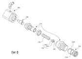
翻斗車(tipping truck)通常是透過舉重液壓系統控制其車斗的傾斜程度。車輛的舉重液壓系統是以氣壓控制液壓,液壓泵將液壓油輸入至舉升控制閥(tipping valve)。 A tipping truck usually controls the tilt of its body through a weightlifting hydraulic system. The weightlifting hydraulic system of the vehicle uses air pressure to control the hydraulic pressure, and the hydraulic pump inputs the hydraulic oil to the tipping valve.
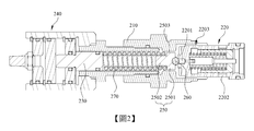
舉升控制閥通常會配置一先導式洩壓閥(pilot relief valve)。如圖1和圖2所示,先導式洩壓閥包括一套筒210、一閥體220、一活塞230、一調整件240、一支撐座250、一阻擋件260以及一彈性件270。在舉升控制閥100內的液壓油的壓力未超過預設值以前,閥體220封閉舉升控制閥100的一出口101(參見圖3),以防止液壓油通過閥體220進入舉升控制閥100的出口101,同時彈性件270藉由彈力施予支撐座250和阻擋件260,使得阻擋件260能夠持續封閉閥體220的一通孔2201。
The lift control valve is usually equipped with a pilot relief valve. As shown in FIGS. 1 and 2, the pilot pressure relief valve includes a
如圖3所示,當舉升控制閥100內的液壓油的壓力超過預設值時,液壓油推擠阻擋件260和支撐座250移動,使得阻擋件260脫離通孔2201,支撐座250壓縮彈性件270。此時,少量液壓油通過通孔2201進入套筒210的內部並且沿著閥體220的外側的複數溝槽2203進入舉升控制閥100的出口101。液壓油推擠閥體220,使得閥體220的複數穿孔2202與舉升控制閥100的出口101相通。此時,大量液壓油通過該等穿孔2202進入舉升控制閥100的出口101,液壓油進一步輸
入液壓缸(圖未示),輸入液壓缸的液壓油進一步推動一活塞(圖未示),以控制翻斗車的車斗(圖未示)的升降。
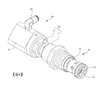
As shown in FIG. 3, when the pressure of the hydraulic oil in the
如圖3所示,液壓油會進入間隙2503中。隨著液壓油的壓力漸漸上升,套筒210內的氣體受到進入間隙2503內的液壓油的推擠之下氣體壓力漸漸上升。當套筒210內的氣體壓力超過預設值時,氣體會推動支撐座250和阻擋件260一起往閥體220的方向移動,使得氣體能夠通過間隙2503,然後沿著套筒210和閥體220之間的空間進入舉升控制閥100的出口101,液壓油則持續進入套筒210的內部,直至套筒210內的氣體全部排出且液壓油充滿套筒210的內部為止,達到壓力平衡的效果。
As shown in Figure 3, hydraulic oil will enter the
然而,氣體推動支撐座250和阻擋件260移動的力量相當大,支撐座250和阻擋件260是以暴衝的方式往閥體220的方向快速移動,導致阻擋件260大力撞擊閥體220,以致於產生以下數種問題:其一,阻擋件260會反覆啟閉通孔2201,閥體220則反覆啟閉舉升控制閥100的出口101,導致舉升控制閥100內的液壓油輸入液壓缸的過程中,液壓油的壓力忽高忽低,十分不穩定;其二,阻擋件260反覆撞擊閥體220,產生震動力和噪音,並且造成阻擋件260和閥體220磨損。
However, the force that the gas pushes the supporting
本發明的主要目的在於提供一種先導式洩壓閥,套筒內的氣體能夠通過支撐座的內部向外排出,液壓油充滿套筒內部,以保持壓力平衡,支撐座和阻擋件不會往閥體的方向暴衝,閥體的穿孔和舉升控制閥的出口保持暢通,舉升控制閥內的液壓油輸入液壓缸的過程中,液壓油的壓力十分穩定。 The main purpose of the present invention is to provide a pilot pressure relief valve, the gas in the sleeve can be discharged through the inside of the support seat, hydraulic oil fills the inside of the sleeve to maintain pressure balance, and the support seat and the blocking part will not flow to the valve. The direction of the body rushes, the perforation of the valve body and the outlet of the lift control valve remain unblocked, and the pressure of the hydraulic oil is very stable when the hydraulic oil in the lift control valve is input into the hydraulic cylinder.
本發明的另一目的在於提供一種先導式洩壓閥,阻擋件不會反覆撞擊閥體,不會產生震動力和噪音,阻擋件和閥體也不會有磨損的問題。 Another object of the present invention is to provide a pilot-operated pressure relief valve in which the blocking member will not repeatedly hit the valve body, vibration and noise will not be generated, and the blocking member and the valve body will not suffer from abrasion.
為了達成前述的目的,本發明提供一種先導式洩壓閥,包括一套筒、一閥體、一活塞、一調整件、一支撐座、一阻擋件以及一彈性件。閥體設置於套筒的一端並且開設一通孔。活塞設置於套筒中。調整件設置於套筒並且用以調整活塞的位置。支撐座設置於套筒中並且包括一頭部及一桿部,頭部具有一第一表面、一第二表面及一外側面並且開設至少一排氣通道,頭部的外側面與套筒的一內側面之間形成一間隙,至少一排氣通道貫穿頭部的第一表面,桿部設置於頭部的第二表面並且開設至少一進氣通道,至少一排氣通道與至少一進氣通道相通。阻擋件設置於頭部的第一表面並且用以啟閉閥體的通孔。彈性件設置於套筒中,套設於桿部,並且其兩端分別抵靠於活塞和頭部的第二表面。 In order to achieve the foregoing objective, the present invention provides a pilot pressure relief valve, which includes a sleeve, a valve body, a piston, an adjusting member, a supporting seat, a blocking member, and an elastic member. The valve body is arranged at one end of the sleeve and has a through hole. The piston is arranged in the sleeve. The adjusting member is arranged on the sleeve and used for adjusting the position of the piston. The support seat is arranged in the sleeve and includes a head and a rod. The head has a first surface, a second surface, and an outer side surface, and at least one exhaust channel is provided. A gap is formed between an inner side surface, at least one exhaust passage penetrates the first surface of the head, the rod is disposed on the second surface of the head and opens at least one intake passage, at least one exhaust passage and at least one intake The channels are connected. The blocking member is arranged on the first surface of the head and used to open and close the through hole of the valve body. The elastic member is arranged in the sleeve and sleeved on the rod, and its two ends are respectively abutted against the second surface of the piston and the head.
較佳地,至少一排氣通道包括一第一通道及一第二通道,至少一第一通道貫穿頭部的第一表面,至少一第二通道連通於至少一第一通道與至少一進氣通道之間。 Preferably, the at least one exhaust passage includes a first passage and a second passage, at least one first passage penetrates the first surface of the head, and at least one second passage communicates with at least one first passage and at least one intake Between channels.
較佳地,頭部開設複數排氣通道,該等第二通道貫穿頭部的外側面,各第二通道位於頭部的外側面的一端形成一開口,該等第二通道的該等開口對稱設置。 Preferably, the head is provided with a plurality of exhaust passages, the second passages pass through the outer surface of the head, and each second passage is located at one end of the outer surface of the head to form an opening, and the openings of the second passages are symmetrical Set up.
較佳地,各第二通道的開口和與各第二通道相通的第一通道位於頭部的同一側。 Preferably, the opening of each second channel and the first channel communicating with each second channel are located on the same side of the head.
較佳地,各第二通道的開口和與各第二通道相通的第一通道位於頭部的相對側。 Preferably, the opening of each second channel and the first channel communicating with each second channel are located on opposite sides of the head.
較佳地,至少一進氣通道沿著桿部的一軸線延伸並且貫穿桿部的兩端。 Preferably, at least one air inlet passage extends along an axis of the rod portion and penetrates both ends of the rod portion.
較佳地,頭部的第一表面凹設一凹槽,阻擋件設置於凹槽中,該等第一通道沿著一圓周方向環繞凹槽間隔設置並且分別與凹槽之間形成一距離。 Preferably, the first surface of the head is recessed with a groove, the blocking member is arranged in the groove, and the first channels are arranged at intervals around the groove along a circumferential direction and form a distance between the grooves.
較佳地,至少一進氣通道位於桿部的一外側面,沿著桿部的長度方向延伸,並且貫穿桿部的兩端,至少一第二通道位於頭部的第二表面並且沿著頭部的寬度方向延伸。 Preferably, at least one air inlet passage is located on an outer side surface of the stem, extends along the length of the stem, and penetrates both ends of the stem, and at least one second passage is located on the second surface of the head and runs along the head. The part extends in the width direction.
較佳地,頭部開設複數排氣通道,該等第一通道沿著一圓周方向間隔設置,桿部開設複數進氣通道,該等進氣通道沿著一圓周方向間隔設置,該等第二通道分別連通於該等第一通道與該等進氣通道之間。 Preferably, the head portion is provided with a plurality of exhaust passages, the first passages are arranged at intervals along a circumferential direction, the rod portion is provided with a plurality of air inlet passages, the air inlet passages are arranged at intervals along a circumferential direction, and the second passages are arranged at intervals along a circumferential direction. The passages are respectively connected between the first passages and the intake passages.
較佳地,頭部的第一表面凹設一凹槽,阻擋件設置於凹槽中,該等第一通道環繞凹槽並且分別與凹槽之間形成一距離。 Preferably, a groove is recessed on the first surface of the head, and the blocking member is arranged in the groove. The first channels surround the groove and form a distance from the groove.
本發明的功效在於,套筒內的氣體能夠通過支撐座的內部向外排出,液壓油充滿套筒內部,以保持壓力平衡,支撐座和阻擋件不會往閥體的方向暴衝,閥體的穿孔和舉升控制閥的出口保持暢通,舉升控制閥內的液壓油輸入液壓缸的過程中,液壓油的壓力十分穩定。 The effect of the present invention is that the gas in the sleeve can be discharged through the inside of the support seat, hydraulic oil fills the inside of the sleeve to maintain pressure balance, the support seat and the blocking member will not rush toward the valve body, and the valve body The perforation and the outlet of the lift control valve remain unblocked, and the pressure of the hydraulic oil is very stable when the hydraulic oil in the lift control valve is input into the hydraulic cylinder.
再者,阻擋件不會反覆撞擊閥體,不會產生震動力和噪音,阻擋件和閥體也不會有磨損的問題。 Furthermore, the blocking member will not repeatedly hit the valve body, vibration and noise will not be generated, and the blocking member and the valve body will not suffer from abrasion.
10:套筒 10: Sleeve
11:第一筒部 11: The first tube
12:第二筒部 12: The second tube
20:閥體 20: Valve body
21:閥座 21: Valve seat
211:開孔 211: Opening
212:通孔 212: Through hole
213:凹溝 213: Groove
214:穿孔 214: Piercing
215:溝槽 215: groove
22:閥芯 22: Spool
221:小徑部 221: Small Diameter
2211:第一流道 2211: first runner
222:大徑部 222: Large Diameter
2221:第二流道 2221: second runner
23:內蓋 23: inner cover
24:閥體彈性件 24: Valve body elastic parts
30:活塞 30: Piston
31:大徑部 31: Large diameter part
32:小徑部 32: Small diameter part
40:調整件 40: adjustment piece
41:套部 41: Set Department
42:調整活塞 42: Adjust the piston
43:高壓氣體來源 43: Source of high-pressure gas
50,50A,50B:支撐座 50, 50A, 50B: support seat
501:間隙 501: gap
51,51A:頭部 51, 51A: head
511:第一表面 511: First Surface
512,512A:第二表面 512, 512A: second surface
513:外側面 513: outer side
514:排氣通道 514: Exhaust Channel
5141,5141A,5141B:第一通道 5141, 5141A, 5141B: first channel
5142,5142A,5142B:第二通道 5142, 5142A, 5142B: second channel
515:凹槽 515: groove
52,52A:桿部 52, 52A: pole
521,521A:進氣通道 521,521A: intake channel
522A:外側面 522A: Outer side
60:阻擋件 60: stop
70:彈性件 70: Elastic
100:舉升控制閥 100: Lift control valve
101:出口 101: Exit
210:套筒 210: Sleeve
220:閥體 220: valve body
2201:通孔 2201: Through hole
2202:穿孔 2202: perforation
2203:溝槽 2203: groove
230:活塞 230: Piston
240:調整件 240: adjustment piece
250:支撐座 250: support base
2501:頭部 2501: head
2502:桿部 2502: pole
2503:間隙 2503: gap
260:阻擋件 260: Block
270:彈性件 270: Elastic
〔圖1〕是習知的先導式洩壓閥的分解圖。 [Figure 1] is an exploded view of the conventional pilot-operated pressure relief valve.
〔圖2〕是習知的先導式洩壓閥的剖面圖。 [Figure 2] is a cross-sectional view of a conventional pilot-operated pressure relief valve.
〔圖3〕是習知的先導式洩壓閥的使用示意圖。 [Figure 3] is a schematic diagram of the use of a conventional pilot-operated pressure relief valve.
〔圖4〕是本發明的第一實施例的立體圖。 [Figure 4] is a perspective view of the first embodiment of the present invention.
〔圖5〕是本發明的第一實施例的分解圖。 [Figure 5] is an exploded view of the first embodiment of the present invention.
〔圖6〕是本發明的第一實施例的剖面圖。 [Fig. 6] is a cross-sectional view of the first embodiment of the present invention.
〔圖7〕是本發明的第一實施例的支撐座的立體圖。 [Figure 7] is a perspective view of the support base of the first embodiment of the present invention.
〔圖8〕是本發明的第一實施例的支撐座的俯視圖。 [Fig. 8] is a plan view of the support base of the first embodiment of the present invention.
〔圖9〕是沿著圖8的A-A線截取的剖面圖。 [Fig. 9] is a cross-sectional view taken along the line A-A of Fig. 8. [Fig.
〔圖10〕是本發明的第一實施例的使用示意圖。 [Figure 10] is a schematic diagram of the use of the first embodiment of the present invention.
〔圖11〕是本發明的第二實施例的支撐座的立體圖。 [Fig. 11] is a perspective view of the support base of the second embodiment of the present invention.
〔圖12〕是本發明的第二實施例的支撐座的俯視圖。 [Fig. 12] is a plan view of the support base of the second embodiment of the present invention.
〔圖13〕是沿著圖12的B-B線截取的剖面圖。 [Fig. 13] is a cross-sectional view taken along the line B-B of Fig. 12.
〔圖14〕是本發明的第三實施例的支撐座的俯視圖。 [Fig. 14] is a plan view of the support base of the third embodiment of the present invention.
〔圖15〕是沿著圖14的C-C線截取的剖面圖。 [FIG. 15] is a cross-sectional view taken along the line C-C in FIG. 14.
以下配合圖式及元件符號對本發明的實施方式做更詳細的說明,俾使熟習該項技藝者在研讀本說明書後能據以實施。 The following describes the embodiments of the present invention in more detail with the drawings and component symbols, so that those who are familiar with the art can implement it after studying this specification.
如圖4至圖6所示,本發明提供一種先導式洩壓閥,包括一套筒10、一閥體20、一活塞30、一調整件40、一支撐座50、一阻擋件60以及一彈性件70。
As shown in Figures 4 to 6, the present invention provides a pilot pressure relief valve, which includes a
套筒10包括一第一筒部11及一第二筒部12,第一筒部11具有一第一端部及一第二端部,第二筒部12具有一第一端部及一第二端部。如圖10所示,第一筒部11的第一端部用以插設於一舉升控制閥100中,第二筒部12的第二端部位於舉升控制閥100之外。第二筒部12的第一端部插設於第一筒部11的第二端部中,第二筒部12的第二端部位於第一筒部11之外。
The
閥體20包括一閥座21、一閥芯22、一內蓋23及一閥體彈性件24。閥座21包括一第一端部、一第二端部及一外側壁。閥座21的第一端部開設一開孔211,閥座21的第二端部開設一通孔212及複數凹溝213。閥座21的外側壁開設複數穿孔214和複數溝槽215。閥座21的第一端部位於第一筒部11之外並且延伸入舉升控制閥100之內(參見圖10),閥座21的第二端部插設於第一筒部11的第一端部中。閥芯22設置於閥座21的內部,包括一小徑部221及一大徑部222,小徑部221的外側面開設一第一流道2211,大徑部222的內部開設一第二流道2221,第一流道2211與第二流道2221相通,第二流道2221與通孔212相通,舉升控制閥100內的液壓油依序通過第一流道2211和第二流道2221進入通孔212(參見圖10)。內蓋23可移動地套設於閥芯22並且位於閥座21的內部。閥體彈性件24套設於閥芯22,位於內蓋23的內部,並且其兩端抵頂於閥座21和內蓋23。
The
活塞30包括一大徑部31及一小徑部32,大徑部31設置於第二筒部12的第二端部中,小徑部32位於第二筒部12的第二端部之外。
The
調整件40包括一套部41、一調整活塞42及一高壓氣體來源43,套部41設置於第二筒部12的第二端部,調整活塞42設置於套部41中,活塞30的小徑部32設置於調整活塞42上,高壓氣體來源43連接套部41。高壓氣體來源43提供一高壓氣體進入套部41中,藉由高壓氣體的壓力來移動調整活塞42,藉以控
制調整活塞42在套部41內的位置,調整活塞42則可進一步控制活塞30在第二筒部12的第二端部中的位置。
The adjusting
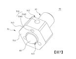
支撐座50設置於第一筒部11中並且包括一頭部51及一桿部52。頭部51具有一第一表面511、一第二表面512及一外側面513並且開設至少一排氣通道514,頭部51的外側面513與第一筒部11的一內側面之間形成一間隙501,至少一排氣通道514貫穿頭部51的第一表面511。桿部52設置於頭部51的第二表面512並且開設至少一進氣通道521,至少一排氣通道514與至少一進氣通道521相通。
The supporting
阻擋件60設置頭部51的第一表面511並且用以啟閉閥座21的通孔212。較佳地,阻擋件60為一鋼珠。
The blocking
彈性件70設置於第二筒部12中,套設於桿部52,並且其兩端分別抵靠於活塞30和頭部51的第二表面512。
The
如圖6所示,在舉升控制閥100內的液壓油的壓力未超過預設值以前,閥體彈性件24保持在自然狀態並且藉由將彈力施予內蓋23,內蓋23得以持續封閉該等穿孔214和舉升控制閥100的一出口101,以防止液壓油通過該等穿孔214進入舉升控制閥100的出口101,同時彈性件70藉由將彈力施予支撐座50和阻擋件60,使得阻擋件60能夠持續封閉閥座21的通孔212。
As shown in FIG. 6, before the pressure of the hydraulic oil in the
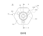
如圖7至圖9所示,在第一實施例中,頭部51開設三排氣通道514,各排氣通道514包括一第一通道5141及一第二通道5142,該等第一通道5141貫穿頭部51的第一表面511,桿部52開設一進氣通道521,進氣通道521沿著桿部52的一軸線延伸並且貫穿桿部52的兩端,該等第二通道5142分別連通於該等第一通道5141與進氣通道521之間。
As shown in FIGS. 7-9, in the first embodiment, the
以下將配合圖10說明本發明的第一實施例的使用方式。 The use of the first embodiment of the present invention will be described below in conjunction with FIG. 10.
當舉升控制閥100內的液壓油的壓力超過預設值時,液壓油推擠阻擋件60和支撐座50往第二筒部12的方向移動,使得阻擋件60脫離通孔212,支撐座50壓縮彈性件70。此時,少量液壓油通過通孔212進入第一筒部11的內部並且沿著該等凹溝213和該等溝槽215進入舉升控制閥100的出口101。液壓油推擠內蓋23往閥座21內部移動,該等穿孔214與舉升控制閥100的出口101相通,內蓋23壓縮閥體彈性件24。此時,大量液壓油通過該等穿孔214進入舉升控制閥100的出口101,液壓油進一步輸入一液壓缸(圖未示),輸入液壓缸的液壓油進一步推動一活塞(圖未示),以控制一翻斗車的一車斗(圖未示)的升降。
When the pressure of the hydraulic oil in the
在阻擋件60脫離通孔212以後,液壓油會往阻擋件60的方向噴射,液壓油噴射到阻擋件60的表面的時候會側向飛濺而呈傘狀流動,以閃過該等第一通道5141在頭部51的第一表面511的開口,以防止液壓油流入該等第一通道5141中。
After the blocking
液壓油會進入間隙501中,隨著液壓油的壓力漸漸上升,第二筒部12內的氣體受到間隙501內的液壓油推擠之下依序通過進氣通道521、該等第二通道5142、該等第一通道5141進入第一筒部11內,進入第一筒部11內的氣體進一步通過該等溝槽215進入舉升控制閥100的出口101。
The hydraulic oil will enter the
因為第二筒部12內的氣體能夠通過支撐座50的內部向外排出,液壓油充滿第二筒部12內部,使得套筒10的內部壓力能夠保持平衡,支撐座50和阻擋件60完全不會往閥座21的方向暴衝,閥座21的該等穿孔214與舉升控制閥100的出口101保持暢通。是以,舉升控制閥100內的液壓油輸入液壓缸的過程中,液壓油的壓力十分穩定。再者,阻擋件60不會反覆撞擊閥座21,不會產生震動力和噪音,阻擋件60和閥座21也不會有磨損的問題。
Because the gas in the
此外,第一實施例的進氣通道521位於桿部52的內部,其側邊呈封閉狀,且與該等第二通道5142相通,因此氣體集中進入進氣通道521且平均且穩定地分配到該等第二通道5142,氣體平均且穩定地從該等第一通道5141向外排出,使得第一實施例的氣體通過支撐座50的內部向外排出的時間較短。
In addition, the
如圖7至圖9所示,該等第二通道5142貫穿頭部51的外側面513,各第二通道5142位於頭部51的外側面513的一端形成一開口,該等第二通道5142的該等開口對稱設置。如圖10所示,氣體在通過該等第二通道5142的過程中,部分氣體會從該等第二通道5142的該等開口向外噴射。因為氣體向外噴射的方向恰好對稱,所以氣體向外噴射的力量恰好能夠讓頭部51保持平衡,不會晃動,也不會偏移,能夠與套筒10保持同軸關係。
As shown in FIGS. 7-9, the
如圖7至圖9所示,各第二通道5142的開口和與各第二通道5142相通的第一通道5141位於頭部51的同一側。藉此,頭部51的中心處的厚度足夠,結構結實,不易破裂,提升支撐座50的使用壽命。
As shown in FIGS. 7 to 9, the opening of each
如圖7至圖9所示,各第二通道5142位於頭部51的內部的一端與進氣通道521相通,各第二通道5142的中間與其中一第一通道5141相通。因為各第二通道5142的開口和與各第二通道5142相通的第一通道5141位於頭部51的同一側的關係,所以第二通道5142只要鑽孔到進氣通道521的一端即可同時與其中一第一通道5141和進氣通道521相通,無須鑽孔太深,節省成本,且可避免過度破壞頭部51的內部結構,提升頭部51的結構強度。
As shown in FIGS. 7 to 9, one end of each
如圖7至圖9所示,頭部51的第一表面511凹設一凹槽515,阻擋件60設置於凹槽515中,該等第一通道5141沿著一圓周方向環繞凹槽515間隔設置,並且分別與凹槽515之間形成一距離。是以,該等第一通道5141在頭部51的
第一表面511的開口不會被阻擋件60擋住,第二筒部12內的氣體能夠均勻且順暢地從該等第一通道5141向外排出。
As shown in FIGS. 7-9, the
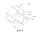
如圖11至圖13所示,第二實施例與第一實施例的差別在於:其一,桿部52A開設三進氣通道521A,該等進氣通道521A位於桿部52A的一外側面522A,沿著一圓周方向間隔設置,沿著桿部52A的長度方向延伸,並且貫穿桿部52A的兩端;以及其二,該等第二通道5142A位於頭部51A的第二表面512A,沿著頭部51A的寬度方向延伸,並且分別連通於該等第一通道5141A與該等進氣通道521A之間。
As shown in FIGS. 11 to 13, the difference between the second embodiment and the first embodiment is: First, the
相較於第一實施例,第二實施例的該等進氣通道521A位於桿部52A的外側面522A,其側邊呈開放狀,且分別與該等第二通道5142A相通,因此氣體分散進入該等進氣通道521A且不平均且不穩定地進入該等第二通道5142A,氣體不平均且不穩定地從該等第一通道5141A向外排出。因此,第二實施例的氣體通過支撐座50A的內部向外排出的時間較長。
Compared with the first embodiment, the
相較於第一實施例,第二實施例的支撐座50A的整體結構被破壞的較少,因此第二實施例的支撐座50A的結構強度較強。
Compared with the first embodiment, the overall structure of the
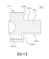
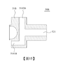
如圖14和圖15所示,第三實施例與第一實施例的差別在於:其一,各第二通道5142B的開口和與各第二通道5142B相通的第一通道5141B位於頭部51B的相對側;其二,各第二通道5142B位於頭部51B的內部的一端和與其相通的第一通道5141B相通;以及其三,各第二通道5142B的中間與進氣通道521相通。
As shown in Figures 14 and 15, the difference between the third embodiment and the first embodiment is: First, the opening of each
相較於第一實施例,因為第三實施例的各第二通道5142B的開口和與各第二通道5142B相通的第一通道5141B位於頭部51B的相對側,所以第三實施例的頭部51B的中心處的厚度不足,結構脆弱,容易破裂。
Compared with the first embodiment, because the opening of each
相較於第一實施例,因為第三實施例的各第二通道5142B的開口和與各第二通道5142B相通的第一通道5141B位於頭部51B的相對側的關係,所以第二通道5142B必須鑽孔到相對側的第一通道5141B的一端才能夠同時與其中一第一通道5141B和進氣通道521相通,鑽孔較深,成本較高,且破壞頭部51B的內部的程度較高,削弱頭部51B的結構強度。
Compared with the first embodiment, because the opening of each
此外,第三實施例的其餘功效和第一實施例的其餘功效完全相同。 In addition, the remaining functions of the third embodiment are completely the same as those of the first embodiment.
以上所述者僅為用以解釋本發明的較佳實施例,並非企圖據以對本發明做任何形式上的限制,是以,凡有在相同的發明精神下所作有關本發明的任何修飾或變更,皆仍應包括在本發明意圖保護的範疇。 The above descriptions are only used to explain the preferred embodiments of the present invention, and are not intended to restrict the present invention in any form. Therefore, any modification or change related to the present invention is made under the same spirit of the invention. , Should still be included in the scope of the invention's intention to protect.
10:套筒 10: Sleeve
11:第一筒部 11: The first tube
12:第二筒部 12: The second tube
20:閥體 20: Valve body
21:閥座 21: Valve seat
211:開孔 211: Opening
213:凹溝 213: Groove
214:穿孔 214: Piercing
215:溝槽 215: groove
22:閥芯 22: Spool
23:內蓋 23: inner cover
30:活塞 30: Piston
31:大徑部 31: Large diameter part
32:小徑部 32: Small diameter part
40:調整件 40: adjustment piece
41:套部 41: Set Department
43:高壓氣體來源 43: Source of high-pressure gas
50:支撐座 50: Support seat
51:頭部 51: head
511:第一表面 511: First Surface
512:第二表面 512: second surface
513:外側面 513: outer side
52:桿部 52: pole
60:阻擋件 60: stop
70:彈性件 70: Elastic
Claims (10)
Priority Applications (3)
| Application Number | Priority Date | Filing Date | Title |
|---|---|---|---|
| TW109121702A TWI730827B (en) | 2020-06-24 | 2020-06-24 | Pilot pressure relief valve |
| CN202010655393.5A CN113833704B (en) | 2020-06-24 | 2020-07-09 | Pilot operated pressure relief valve |
| US17/010,150 US11365821B2 (en) | 2020-06-24 | 2020-09-02 | Pilot relief valve |
Applications Claiming Priority (1)
| Application Number | Priority Date | Filing Date | Title |
|---|---|---|---|
| TW109121702A TWI730827B (en) | 2020-06-24 | 2020-06-24 | Pilot pressure relief valve |
Publications (2)
| Publication Number | Publication Date |
|---|---|
| TWI730827B true TWI730827B (en) | 2021-06-11 |
| TW202200923A TW202200923A (en) | 2022-01-01 |
Family
ID=77517266
Family Applications (1)
| Application Number | Title | Priority Date | Filing Date |
|---|---|---|---|
| TW109121702A TWI730827B (en) | 2020-06-24 | 2020-06-24 | Pilot pressure relief valve |
Country Status (3)
| Country | Link |
|---|---|
| US (1) | US11365821B2 (en) |
| CN (1) | CN113833704B (en) |
| TW (1) | TWI730827B (en) |
Families Citing this family (1)
| Publication number | Priority date | Publication date | Assignee | Title |
|---|---|---|---|---|
| CN116748089B (en) * | 2023-08-11 | 2023-11-14 | 苏州卓兆点胶股份有限公司 | Automatic pressure stabilizing valve for photovoltaic frame gluing |
Citations (4)
| Publication number | Priority date | Publication date | Assignee | Title |
|---|---|---|---|---|
| CN205064962U (en) * | 2015-09-30 | 2016-03-02 | 暴晗 | Safe pilot valve |
| CN208764012U (en) * | 2018-08-31 | 2019-04-19 | 山东奇威特太阳能科技有限公司 | Safety valve |
| TW202022264A (en) * | 2018-09-18 | 2020-06-16 | 美商太陽水力有限責任公司 | Electrohydraulic normally-open ventable valve configured to operate in pressure relief mode when actuated |
| CN211976005U (en) * | 2020-01-03 | 2020-11-20 | 北京宏运立新高新技术有限公司 | Pressure reducing valve |
Family Cites Families (8)
| Publication number | Priority date | Publication date | Assignee | Title |
|---|---|---|---|---|
| CA1114716A (en) * | 1978-10-10 | 1981-12-22 | Kysor Industrial Corporation | Hydraulic responsive air control valve |
| JP2007239961A (en) * | 2006-03-10 | 2007-09-20 | Sun Hydraulics Corp | Soft vent relief valve |
| WO2011145753A1 (en) * | 2010-05-17 | 2011-11-24 | 볼보 컨스트럭션 이큅먼트 에이비 | Pressure control valve |
| CN102287412B (en) * | 2011-09-22 | 2013-09-25 | 宁波汉商液压有限公司 | Ultra-high pressure proportional relief valve |
| CN203627906U (en) * | 2014-01-07 | 2014-06-04 | 温州市捷宇阀门制造有限公司 | Pilot pressure-relieving valve |
| CN203686277U (en) * | 2014-01-15 | 2014-07-02 | 宁波埃美柯铜阀门有限公司 | Safety relief valve |
| CN109058208B (en) * | 2018-10-17 | 2020-05-22 | 浙江奥诗柯流体控制股份有限公司 | Buffer overflow valve |
| CN109139593B (en) * | 2018-10-22 | 2020-05-26 | 安徽诺乐知识产权服务有限公司 | Pilot unloading valve |
-
2020
- 2020-06-24 TW TW109121702A patent/TWI730827B/en active
- 2020-07-09 CN CN202010655393.5A patent/CN113833704B/en active Active
- 2020-09-02 US US17/010,150 patent/US11365821B2/en active Active
Patent Citations (4)
| Publication number | Priority date | Publication date | Assignee | Title |
|---|---|---|---|---|
| CN205064962U (en) * | 2015-09-30 | 2016-03-02 | 暴晗 | Safe pilot valve |
| CN208764012U (en) * | 2018-08-31 | 2019-04-19 | 山东奇威特太阳能科技有限公司 | Safety valve |
| TW202022264A (en) * | 2018-09-18 | 2020-06-16 | 美商太陽水力有限責任公司 | Electrohydraulic normally-open ventable valve configured to operate in pressure relief mode when actuated |
| CN211976005U (en) * | 2020-01-03 | 2020-11-20 | 北京宏运立新高新技术有限公司 | Pressure reducing valve |
Also Published As
| Publication number | Publication date |
|---|---|
| US20210404571A1 (en) | 2021-12-30 |
| TW202200923A (en) | 2022-01-01 |
| CN113833704A (en) | 2021-12-24 |
| US11365821B2 (en) | 2022-06-21 |
| CN113833704B (en) | 2024-02-06 |
Similar Documents
| Publication | Publication Date | Title |
|---|---|---|
| CN108350909B (en) | Fluid control valve | |
| JP3417564B2 (en) | Fluid-operated impact rock device | |
| TWI730827B (en) | Pilot pressure relief valve | |
| CN203641148U (en) | Balance valve and hydraulic cylinder telescopic control loop | |
| US7766035B2 (en) | Fluid jet for providing fluid under pressure to a desired location | |
| US7198120B2 (en) | Down-the-hole drill assembly | |
| JP2009264515A5 (en) | ||
| HU192333B (en) | Check valve controllable hydraulically for the working cylinders of frame sets | |
| JP5282195B2 (en) | Fluid pressure equipment | |
| KR102069042B1 (en) | Impact-driven tool | |
| KR101011944B1 (en) | Hydraulic control unit including regeneration unit and brake valve | |
| CN107250569A (en) | Pneumatic cylinder with damped sleeve | |
| CN104481952A (en) | One-way throttle valve and lift cylinder control system | |
| CN103075569B (en) | Flow noise limiter | |
| JP3992087B2 (en) | Damping force generation structure | |
| KR102347132B1 (en) | Wheel valve for ctis | |
| JP2001082294A (en) | Control valve for fuel injection valve | |
| KR20130015363A (en) | Oil control valve | |
| GB2279131A (en) | Choke valve | |
| RU2001121822A (en) | Pressure relief valve | |
| JP4657519B2 (en) | Shock absorber | |
| CN221347715U (en) | Shock absorber, suspension and vehicle | |
| CN222277059U (en) | Piston type energy accumulator | |
| KR102005002B1 (en) | Tip device for high pressure injection | |
| KR20180115025A (en) | counter balance valve for hydraulic winch |