TWI697765B - Adapting device and cooling system having the same - Google Patents
Adapting device and cooling system having the same Download PDFInfo
- Publication number
- TWI697765B TWI697765B TW108108471A TW108108471A TWI697765B TW I697765 B TWI697765 B TW I697765B TW 108108471 A TW108108471 A TW 108108471A TW 108108471 A TW108108471 A TW 108108471A TW I697765 B TWI697765 B TW I697765B
- Authority
- TW
- Taiwan
- Prior art keywords
- liquid
- switching valve
- branch
- cooling liquid
- interface
- Prior art date
Links
- 238000001816 cooling Methods 0.000 title abstract description 11
- 238000009826 distribution Methods 0.000 claims abstract description 139
- 239000002826 coolant Substances 0.000 claims abstract description 61
- 239000007788 liquid Substances 0.000 claims description 145
- 239000000110 cooling liquid Substances 0.000 claims description 105
- 230000017525 heat dissipation Effects 0.000 claims description 21
- 238000010586 diagram Methods 0.000 description 13
- 230000001965 increasing effect Effects 0.000 description 9
- 238000013461 design Methods 0.000 description 3
- 230000000694 effects Effects 0.000 description 3
- 238000005259 measurement Methods 0.000 description 3
- 238000000034 method Methods 0.000 description 3
- 230000003068 static effect Effects 0.000 description 3
- XLYOFNOQVPJJNP-UHFFFAOYSA-N water Substances O XLYOFNOQVPJJNP-UHFFFAOYSA-N 0.000 description 3
- 230000007423 decrease Effects 0.000 description 2
- 230000003247 decreasing effect Effects 0.000 description 2
- 238000001514 detection method Methods 0.000 description 2
- 238000011161 development Methods 0.000 description 2
- 230000002708 enhancing effect Effects 0.000 description 2
- 238000004519 manufacturing process Methods 0.000 description 2
- 238000010992 reflux Methods 0.000 description 2
- 230000001754 anti-pyretic effect Effects 0.000 description 1
- 239000002221 antipyretic Substances 0.000 description 1
- 238000005516 engineering process Methods 0.000 description 1
- 238000009434 installation Methods 0.000 description 1
- 238000012986 modification Methods 0.000 description 1
- 230000004048 modification Effects 0.000 description 1
- 238000012545 processing Methods 0.000 description 1
- 238000005086 pumping Methods 0.000 description 1
- 238000003860 storage Methods 0.000 description 1
- 238000012546 transfer Methods 0.000 description 1
Images


Classifications
-
- F—MECHANICAL ENGINEERING; LIGHTING; HEATING; WEAPONS; BLASTING
- F28—HEAT EXCHANGE IN GENERAL
- F28F—DETAILS OF HEAT-EXCHANGE AND HEAT-TRANSFER APPARATUS, OF GENERAL APPLICATION
- F28F27/00—Control arrangements or safety devices specially adapted for heat-exchange or heat-transfer apparatus
- F28F27/02—Control arrangements or safety devices specially adapted for heat-exchange or heat-transfer apparatus for controlling the distribution of heat-exchange media between different channels
-
- H—ELECTRICITY
- H05—ELECTRIC TECHNIQUES NOT OTHERWISE PROVIDED FOR
- H05K—PRINTED CIRCUITS; CASINGS OR CONSTRUCTIONAL DETAILS OF ELECTRIC APPARATUS; MANUFACTURE OF ASSEMBLAGES OF ELECTRICAL COMPONENTS
- H05K7/00—Constructional details common to different types of electric apparatus
- H05K7/20—Modifications to facilitate cooling, ventilating, or heating
- H05K7/20709—Modifications to facilitate cooling, ventilating, or heating for server racks or cabinets; for data centers, e.g. 19-inch computer racks
- H05K7/20763—Liquid cooling without phase change
- H05K7/20781—Liquid cooling without phase change within cabinets for removing heat from server blades
-
- H—ELECTRICITY
- H05—ELECTRIC TECHNIQUES NOT OTHERWISE PROVIDED FOR
- H05K—PRINTED CIRCUITS; CASINGS OR CONSTRUCTIONAL DETAILS OF ELECTRIC APPARATUS; MANUFACTURE OF ASSEMBLAGES OF ELECTRICAL COMPONENTS
- H05K7/00—Constructional details common to different types of electric apparatus
- H05K7/20—Modifications to facilitate cooling, ventilating, or heating
- H05K7/20218—Modifications to facilitate cooling, ventilating, or heating using a liquid coolant without phase change in electronic enclosures
- H05K7/20272—Accessories for moving fluid, for expanding fluid, for connecting fluid conduits, for distributing fluid, for removing gas or for preventing leakage, e.g. pumps, tanks or manifolds
-
- F—MECHANICAL ENGINEERING; LIGHTING; HEATING; WEAPONS; BLASTING
- F28—HEAT EXCHANGE IN GENERAL
- F28F—DETAILS OF HEAT-EXCHANGE AND HEAT-TRANSFER APPARATUS, OF GENERAL APPLICATION
- F28F9/00—Casings; Header boxes; Auxiliary supports for elements; Auxiliary members within casings
- F28F9/001—Casings in the form of plate-like arrangements; Frames enclosing a heat exchange core
-
- H—ELECTRICITY
- H05—ELECTRIC TECHNIQUES NOT OTHERWISE PROVIDED FOR
- H05K—PRINTED CIRCUITS; CASINGS OR CONSTRUCTIONAL DETAILS OF ELECTRIC APPARATUS; MANUFACTURE OF ASSEMBLAGES OF ELECTRICAL COMPONENTS
- H05K7/00—Constructional details common to different types of electric apparatus
- H05K7/20—Modifications to facilitate cooling, ventilating, or heating
- H05K7/20218—Modifications to facilitate cooling, ventilating, or heating using a liquid coolant without phase change in electronic enclosures
-
- H—ELECTRICITY
- H05—ELECTRIC TECHNIQUES NOT OTHERWISE PROVIDED FOR
- H05K—PRINTED CIRCUITS; CASINGS OR CONSTRUCTIONAL DETAILS OF ELECTRIC APPARATUS; MANUFACTURE OF ASSEMBLAGES OF ELECTRICAL COMPONENTS
- H05K7/00—Constructional details common to different types of electric apparatus
- H05K7/20—Modifications to facilitate cooling, ventilating, or heating
- H05K7/20709—Modifications to facilitate cooling, ventilating, or heating for server racks or cabinets; for data centers, e.g. 19-inch computer racks
- H05K7/20763—Liquid cooling without phase change
Landscapes
- Engineering & Computer Science (AREA)
- Microelectronics & Electronic Packaging (AREA)
- Physics & Mathematics (AREA)
- Thermal Sciences (AREA)
- General Engineering & Computer Science (AREA)
- Computer Hardware Design (AREA)
- Mechanical Engineering (AREA)
- Cooling Or The Like Of Electrical Apparatus (AREA)
Abstract
Description
本發明係關於一種轉接裝置,特別是一種用於冷卻液分配裝置之轉接裝置以及包含其之散熱系統。 The present invention relates to an adapter device, in particular to an adapter device for a cooling liquid distribution device and a heat dissipation system containing the adapter device.
隨著大數據與互聯網時代的來臨,提供雲端服務的需求急遽地提升,因此,用於這些服務的電子計算機設備,如網路儲存設備或伺服器設備等的處理運算能力也不斷地被增強,導致產生的熱量也越來越多。如何有效地對存放大量伺服器的伺服器機櫃進行散熱,是直接影響運算效能與電子設備壽命的關鍵之一。 With the advent of the era of big data and the Internet, the demand for providing cloud services is rapidly increasing. Therefore, the processing and computing capabilities of electronic computer equipment used for these services, such as network storage equipment or server equipment, have also been continuously enhanced. The heat generated is also increasing. How to effectively dissipate heat from a server cabinet storing a large number of servers is one of the keys that directly affects computing performance and the life of electronic equipment.
因此,水冷技術逐漸受到重視。水冷的手段大致上是以冷卻液作為散熱媒介,再搭配泵浦驅使冷卻液在所應用的系統內形成不斷的循環,循環的路徑透過管路的配置所實現,這些管路可分佈於系統內欲解熱的電子元件上,當溫度相對較低的冷卻液流經溫度相對較高的電子元件時,便可直接吸收其熱能以降低電子元件的溫度,吸收熱量的冷卻液將隨著管路至其他區域進行熱交換來釋放熱能,以降低冷卻液的溫度而使其可重新回到系統內進行循環。 Therefore, water cooling technology has gradually received attention. The method of water cooling is basically the cooling liquid as the heat dissipation medium, and the pump is used to drive the cooling liquid to form a continuous circulation in the applied system. The circulation path is realized by the configuration of pipelines, which can be distributed in the system For electronic components to be deheated, when a relatively low temperature coolant flows through a relatively high temperature electronic component, it can directly absorb its heat energy to reduce the temperature of the electronic component, and the coolant that absorbs heat will follow the pipeline to Other areas perform heat exchange to release heat energy to lower the temperature of the coolant so that it can return to the system for circulation.
針對同時於多處具有熱源的伺服器機櫃,已有業者開發冷卻液分配裝置(coolant distribution unit,CDU),其可以預先設定的流量與壓力,直接將冷卻液經由分流管裝置(manifold)同時輸送至伺服器機櫃上不同處的伺服器主機,從而同時對這些伺服器主機進行冷卻的作業。該分配裝置可相應搭配前述的泵浦與熱交換機制等,從而可使冷卻液不斷地進行冷卻循環。 For server cabinets with multiple heat sources at the same time, the industry has developed a coolant distribution unit (coolant distribution unit, CDU), which can directly deliver the coolant at the same time through a manifold at a preset flow rate and pressure. To server hosts in different places on the server cabinet, so as to perform cooling operations on these server hosts at the same time. The distribution device can be matched with the aforementioned pumping and heat exchange mechanism, etc., so that the cooling liquid can be continuously cooled and circulated.
然而,目前市面上的冷卻液分配裝置的設計都是以體積小、方便安裝以及規格化為優先,以符合中小型的企業用戶的需求。但,面臨現今伺服器效能不斷提升使得能量密度急遽成長的趨勢,傳統的冷卻液分配裝置的流量(flow rate)與靜壓(static pressure)已不足夠,難以提供更高的流量或是靜壓以提供足夠的解熱能力。同時,依據各家企業對於伺服器的散熱需求有所不同,傳統制式化規格的冷卻液分配裝置常難以確實滿足使用者的需求,若欲自行研發特製規格的冷卻液分配裝置,其所增加的成本恐不符經濟效益。 However, the current design of the coolant distribution device on the market is to give priority to small size, easy installation and standardization to meet the needs of small and medium-sized enterprise users. However, facing the current trend of increasing server performance and rapidly increasing energy density, the flow rate and static pressure of the traditional coolant distribution device are no longer sufficient, and it is difficult to provide higher flow or static pressure. To provide sufficient antipyretic capacity. At the same time, according to the different heat dissipation requirements of various companies for the server, the traditional standard specifications of the coolant distribution device is often difficult to truly meet the needs of users, if you want to develop a special specification of the coolant distribution device, its increased The cost may not match the economic benefits.
因此,有必要針對傳統的冷卻液分配裝置的規格與散熱能力不符需求的問題提出解決方案。 Therefore, it is necessary to provide a solution to the problem that the specifications and heat dissipation capacity of the traditional coolant distribution device do not meet the requirements.
有鑑於此,本發明提供一種轉接裝置以及包含其之散熱系統,可藉以使現有的冷卻液分配裝置進行組合而提供更高流量或靜壓的效果。 In view of this, the present invention provides an adapter device and a heat dissipation system including the adapter device, which can combine existing coolant distribution devices to provide a higher flow rate or static pressure effect.
根據本發明之一實施例揭露了一種散熱系統,包含一機櫃、多個冷卻液分配裝置以及至少一轉接裝置。機櫃具有出液分流管與進液分流管。冷卻液分配裝置設置於機櫃上且各具有冷卻液分配出口與冷卻液分配入口。轉接裝置設置於機櫃上且包含殼體與多個切換閥。殼體具有多個第一入液口、多個第一出液口、至少一第二入液口以及至少一第二出液口,其中第一入液口用以分別連通冷卻液分配裝置的多個冷卻液分配出口,第一出液口用以分別連通冷卻液分配裝置的多個冷卻液分配入口,第二入液口連接機櫃之出液分流管,第二出液口連接機櫃之進液分流管。切換閥設置於殼體中且連接於第一入液口、第一出液口、第二入液口以及第二出液口,以用以改變第一入液口、第一出液口、第二入液口以及第二出液口之間的連接關係,從而改變冷卻液分配裝置之間的連接關係。 According to an embodiment of the present invention, a heat dissipation system is disclosed, which includes a cabinet, a plurality of cooling liquid distribution devices, and at least one adapter device. The cabinet has a liquid outlet shunt pipe and a liquid inlet shunt pipe. The cooling liquid distribution device is arranged on the cabinet and each has a cooling liquid distribution outlet and a cooling liquid distribution inlet. The adapter device is arranged on the cabinet and includes a housing and a plurality of switching valves. The housing has a plurality of first liquid inlets, a plurality of first liquid outlets, at least one second liquid inlet, and at least one second liquid outlet, wherein the first liquid inlets are used to respectively communicate with the cooling liquid distribution device Multiple cooling liquid distribution outlets, the first liquid outlet is used to respectively communicate with the multiple cooling liquid distribution inlets of the cooling liquid distribution device, the second liquid inlet is connected to the outlet shunt pipe of the cabinet, and the second liquid outlet is connected to the inlet of the cabinet Liquid splitter. The switching valve is arranged in the housing and connected to the first liquid inlet, the first liquid outlet, the second liquid inlet and the second liquid outlet to change the first liquid inlet, the first liquid outlet, The connection relationship between the second liquid inlet and the second liquid outlet changes the connection relationship between the cooling liquid distribution devices.
根據本發明之另一實施例揭露了一種轉接裝置,用以連接於多個冷卻液分配裝置與機櫃之間,轉接裝置包含多個切換閥,用以改變冷 卻液分配裝置與機櫃之間的連接關係。 According to another embodiment of the present invention, an adapter device is disclosed for connecting between a plurality of coolant distribution devices and a cabinet. The adapter device includes a plurality of switching valves for changing the cooling liquid The connection relationship between the liquid distribution device and the cabinet.
根據前述本發明前述實施例所揭露的轉接裝置以及散熱系統,由於切換閥可用以改變冷卻液分配裝置與殼體之間的連接關係,進而可調節冷卻液分配裝置整體的總輸出量或壓力,以達到以現有之冷卻液分配裝置來廣泛地適用於多種不同的散熱需求。 According to the adapter device and the heat dissipation system disclosed in the foregoing embodiments of the present invention, the switching valve can be used to change the connection relationship between the cooling liquid distribution device and the housing, thereby adjusting the total output or pressure of the cooling liquid distribution device as a whole , In order to achieve the existing cooling liquid distribution device is widely applicable to a variety of different heat dissipation requirements.
在此情況下,本發明之轉接裝置可相容並整合市面上現有的各種不同規格的冷卻液分配裝置與管路,調整性與組合彈性高,且不需要更改現有的架構,即不需要額外增加更動設計或開發的成本,有助於節省硬體設施的成本,進而提升實務上的競爭力。 In this case, the adapter device of the present invention can be compatible with and integrate various coolant distribution devices and pipelines of different specifications on the market, with high adjustability and flexibility of combination, and there is no need to modify the existing structure, that is, no The additional cost of design or development changes can help save the cost of hardware facilities, thereby enhancing practical competitiveness.
以上之關於本發明揭露內容之說明及以下之實施方式之說明,係用以示範與解釋本發明之精神與原理,並且提供本發明之專利申請範圍更進一步之解釋。 The above description of the disclosure of the present invention and the following description of the embodiments are used to demonstrate and explain the spirit and principle of the present invention, and to provide a further explanation of the scope of the patent application of the present invention.
1:轉接裝置 1: Adapter
10:殼體 10: Shell
11:第一入液口 11: The first liquid inlet
12:第一出液口 12: The first liquid outlet
13:第二入液口 13: The second liquid inlet
14:第二出液口 14: The second liquid outlet
A:區域 A: area
B:區域 B: area
CDU:冷卻液分配裝置 CDU: Coolant distribution device
CDUout:冷卻液分配出口 CDU out : Coolant distribution outlet
CDUin:冷卻液分配入口 CDU in : Coolant distribution inlet
F:流量計 F: Flowmeter
M1:進液分流管 M1: Liquid inlet manifold
M2:出液分流管 M2: Outlet shunt pipe
O1:第一接口 O1: First interface
O2:第二接口 O2: second interface
O3:第三接口 O3: third interface
O4:第一接口 O4: First interface
O5:第二接口 O5: second interface
O6:第三接口 O6: third interface
P:壓力計 P: pressure gauge
R:機櫃、伺服器機櫃 R: cabinet, server cabinet
S:散熱系統 S: cooling system
SV1:第一切換閥 SV1: The first switching valve
SV2:第二切換閥 SV2: Second switching valve
T1:第一多通管 T1: The first multi-way tube
T2:第二多通管 T2: The second multi-way tube
T11:第一支管 T11: The first pipe
T12:第二支管 T12: second pipe
T13:第三支管 T13: The third branch
T21:第一支管 T21: The first tube
T22:第二支管 T22: second pipe
T23:第三支管 T23: The third branch
圖1A~1B係為應用本發明之一實施例的轉接裝置的散熱系統於不同視角的立體示意圖。 1A to 1B are three-dimensional schematic diagrams of a heat dissipation system of an adapter device according to an embodiment of the present invention in different viewing angles.
圖2係為圖1A之轉接裝置與冷卻液分配裝置及伺服器機櫃的線路連接示意圖。 Fig. 2 is a schematic diagram of the circuit connection between the adapter device and the coolant distribution device and the server cabinet of Fig. 1A.
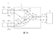
圖3A係為冷卻液分配裝置透過轉接裝置並聯時的線路連接示意圖。 Fig. 3A is a schematic diagram of the circuit connection when the coolant distribution device is connected in parallel through the adapter device.
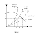
圖3B係為圖3A之冷卻液分配裝置並聯後泵浦的性能曲線圖。 Fig. 3B is a graph showing the pump performance of the cooling liquid distribution device of Fig. 3A after being connected in parallel.
圖4A係為冷卻液分配裝置透過轉接裝置串聯時的線路連接示意圖。 Fig. 4A is a schematic diagram of the line connection when the coolant distribution device is connected in series through the adapter device.
圖4B係為圖4A之冷卻液分配裝置串聯後泵浦的性能曲線圖。 FIG. 4B is a graph showing the performance curve of the pump after the cooling liquid distribution device of FIG. 4A is connected in series.
圖5係為三個冷卻液分配裝置透過轉接裝置串聯以及並聯時的線路連接示意圖。 Figure 5 is a schematic diagram of the circuit connection when three coolant distribution devices are connected in series and in parallel through the adapter device.
以下在實施方式中詳細敘述本發明之詳細特徵以及優點,其內容足以使任何熟習相關技藝者,瞭解本發明之技術內容並據以實施,且根據本說明書所揭露之內容、申請專利範圍及圖式,任何熟習相關技藝者可輕易地理解本發明相關之目的及優點。以下之實施例係進一步詳細說明本發明之觀點,但非以任何觀點限制本發明之範疇。 The detailed features and advantages of the present invention are described in detail in the following embodiments. The content is sufficient to enable anyone familiar with the relevant art to understand the technical content of the present invention and implement it accordingly, and according to the content disclosed in this specification, the scope of patent application and drawings In this way, anyone who is familiar with the relevant art can easily understand the purpose and advantages of the present invention. The following examples further illustrate the viewpoints of the present invention in detail, but do not limit the scope of the present invention by any viewpoint.
此外,以下將以圖式揭露本發明之實施例,且許多實務上的細節將在以下敘述中一併說明,但這些實務上的細節非用以限制本發明。並且,於本案之圖式中,一些習知慣用的結構與元件可能會以簡單示意的方式繪示以保持圖面整潔,且圖式中部份的特徵可能會略為放大或改變其比例或尺寸,以便於理解本發明之技術特徵。 In addition, the embodiments of the present invention will be disclosed in the following figures, and many practical details will be described in the following description, but these practical details are not intended to limit the present invention. In addition, in the drawings in this case, some conventionally used structures and elements may be drawn in a simple schematic way to keep the drawing surface clean, and some of the features in the drawings may be slightly enlarged or their scale or size may be changed. , In order to understand the technical features of the present invention.
另外,以下文中可能使用「部」、「部分」或「處」等術語來描述特定元件之間的特定技術特徵,但這些元件與結構並不以此為限。並且,在下文中也可能使用「實質上」、「基本上」或「約」等術語,為意欲涵蓋可能存在於尺寸、濃度、溫度等性質或特性之範圍的上限及/或下限的偏差、或表示容許製造公差的可接受偏離,但仍可達到所預期的效果。 In addition, terms such as "part", "part" or "location" may be used in the following text to describe specific technical features between specific elements, but these elements and structures are not limited thereto. In addition, terms such as "substantially", "substantially" or "about" may also be used in the following to cover the deviations that may exist in the upper and/or lower limits of the range of properties or characteristics such as size, concentration, temperature, etc., or Represents the acceptable deviation of allowable manufacturing tolerances, but still achieves the desired effect.
再者,除非另有定義,本文所使用的詞彙,在本說明書中應被解讀為與本發明相關技術領域具有一致的意涵。除非有特別明確的定義,這些詞彙將不被解釋為過於理想化的或正式的意涵。 Furthermore, unless otherwise defined, the terms used herein should be interpreted as having the same meaning in the technical field related to the present invention in this specification. Unless there is a clear definition, these words will not be interpreted as overly ideal or formal meaning.
首先,請參照圖1A~1B,圖1A~1B係為應用本發明之一實施例的轉接裝置的伺服器機櫃於不同視角的立體示意圖。本實施例提出一種具有轉接裝置1之散熱系統S,如圖所示,轉接裝置1被配置於一機櫃R,於此實施例中,機櫃R是以伺服器機櫃為例,因此以下也可將其稱為伺服器機櫃R,但本發明並非以此為限,也非以伺服器機櫃R及其規格或其可容置之伺服器主機的數量等為限。此外,伺服器機櫃R上還可配置有一或多個冷卻液分配裝置(coolant distribution unit,CDU)CDU,但本發明並
非以冷卻液分配裝置CDU的規格或擺放位置為限,且伺服器機櫃R上的冷卻液分配裝置CDU的規格可以相同或不相同。
First of all, please refer to FIGS. 1A to 1B. FIGS. 1A to 1B are three-dimensional schematic diagrams of a server cabinet using a switch device according to an embodiment of the present invention from different perspectives. This embodiment proposes a heat dissipation system S with an
對於單個冷卻液分配裝置CDU來說,可對通過其之冷卻液進行特定的分配,例如可限制冷卻液以特定的流量或壓力進行傳輸,但這端看該冷卻液分配裝置CDU於製造時的設定而定,本發明並非以此為限。然而,冷卻液分配裝置CDU的規格為制式規格,即使有調整的空間,也難以滿足某些特殊的流量或壓力需求,並且,當伺服器機櫃R上的伺服器主機的數量有所增減,單個冷卻液分配裝置CDU所能提供的出水量或壓力常有不夠情況發生。因此,本實施例提出的轉接裝置1,可整合多個冷卻液分配裝置CDU,並調整這些冷卻液分配裝置CDU的組合方式,例如改變其串聯或並聯的方式,以適應性地將這些冷卻液分配裝置CDU整體的性能調節至所需的數值,以滿足實際的散熱需求。
For a single cooling liquid distribution device CDU, the cooling liquid passing through it can be specifically distributed, for example, the cooling liquid can be restricted to be transmitted at a specific flow or pressure, but this depends on the cooling liquid distribution device CDU at the time of manufacture Depending on the setting, the present invention is not limited to this. However, the specifications of the coolant distribution device CDU are standard specifications. Even if there is room for adjustment, it is difficult to meet certain special flow or pressure requirements. Moreover, when the number of server hosts on the server rack R increases or decreases, The water output or pressure provided by a single coolant distribution device CDU is often insufficient. Therefore, the
接著,先針對轉接裝置1、冷卻液分配裝置CDU與伺服器機櫃R大致上的連接關係進行說明。於本實施例或其他實施例中,伺服器機櫃R的側牆(未標號)上還配置有進液分流管(manifold)M1與出液分流管M2,但本發明並非以這些分流管以及其規格為限,轉接裝置1可用於將冷卻液連通於這些冷卻液分配裝置CDU與伺服器機櫃R之進液分流管M1與出液分流管M2之間。具體來說,轉接裝置1之一殼體10上可例如具有多個第一入液口11、多個第一出液口12、至少一第二入液口13以及至少一第二出液口14。冷卻液分配裝置CDU可將冷卻液從其之冷卻液分配出口CDUout經由管路(未標號)均勻地送至轉接裝置1之第一入液口11,轉接裝置1可接著從其第二出液口14經由管路(未標號)均勻地送至伺服器機櫃R之進液分流管M1,從而經由進液分流管M1將冷卻液分配給伺服器機櫃R上的伺服器主機之冷盤(cold plate)(未繪示)以吸收熱能。接著,吸收熱能而升溫或汽化的冷卻液可從伺服器機櫃R之出液分流管M2經由管路(未標號)送至轉接裝置1之第二入液口13而回到轉接裝置1,接著轉接裝置1
可將冷卻液從其第一出液口12經由管路(未標號)均勻地送至冷卻液分配裝置CDU之冷卻液分配入口CDUin,冷卻液分配裝置CDU可接著透過管路(未繪示)將冷卻液送至外部連接或其自身的熱交換器進行熱交換以釋放熱能,以將冷卻的冷卻液送回而完成冷卻循環。
Next, the general connection relationship between the
然需聲明的是,本發明並非以冷卻液或其上的冷卻循環路徑為限,且在前述循環的過程中,冷卻液可在液態、汽態或是汽液態共存之間變化,本發明也非以此為限。此外,前述第一入液口11、第一出液口12、第二入液口13以及第二出液口14的數量應可依據實際需求進行調整,例如可對應冷卻液分配裝置CDU的數量等因素進行調整,本發明亦非以前述為限。
However, it needs to be stated that the present invention is not limited to the cooling liquid or the cooling circulation path on it, and during the foregoing cycle, the cooling liquid can change between liquid, vapor or vapor-liquid coexistence. The present invention also Not limited to this. In addition, the number of the aforementioned first
接著,將針對轉接裝置1之內部配置進行介紹,以具體說明如何透過轉接裝置1以調節冷卻液分配裝置CDU整體的性能。請接續參閱圖2,係為本實施例之轉接裝置1與冷卻液分配裝置CDU及伺服器機櫃R的線路連接示意圖。需聲明的是,圖2僅為示意性簡圖,目的是便於理解轉接裝置1的線路連接關係,並非為轉接裝置1之內部結構於實際空間中的分佈情形,因此,圖2中之轉接裝置1的第一入液口11、第一出液口12、第二入液口13、第二出液口14及/或其他元件或管路之間的相對位置關係可能有適應性調整,但本發明並非以此為限,且對於轉接裝置1的運作上也無實質上影響。此外,本實施例之轉接裝置1僅為本發明之轉接裝置的其中一種實施態樣,其旨在於說明本發明之精神之用,但本發明並非以此為限。
Next, the internal configuration of the
於本實施例中,轉接裝置1還可包含一第一切換閥SV1、一第二切換閥SV2、一第一多通管T1、一第二多通管T2以及多個內部管路(未標號)以連接前述元件。所述的切換閥SV1與SV2可以但不限於是機械式或是電磁式的三通閥或多通閥,於本實施例的情況,第一切換閥SV1與第二切換閥SV2例如均為三通閥,但本發明並非以此為限。所述的第一
多通管T1與第二多通管T2可以但不限於是具有三個支管的T型或Y型,但本發明並非以此為限,其支管的數量應可依據實際需求進行增減。
In this embodiment, the
進一步來看,於本實施例中,第一切換閥SV1具有一第一接口O1、一第二接口O2及一第三接口O3,其中,第一切換閥SV1可進行切換,以選擇性地將第一接口O1連通第二接口O2或第三接口O3;第二切換閥SV2具有一第一接口O4、一第二接口O5及一第三接口O6,其中,第二切換閥SV2可進行切換,以選擇性地將第一接口O4連通第二接口O5或第三接口O6。此外,第一多通管T1具有一第一支管T11、一第二支管T12及一第三支管T13;而第二多通管T2具有一第一支管T21、一第二支管T22及一第三支管T23。 Looking further, in this embodiment, the first switching valve SV1 has a first port O1, a second port O2, and a third port O3. The first switching valve SV1 can be switched to selectively switch The first port O1 is connected to the second port O2 or the third port O3; the second switching valve SV2 has a first port O4, a second port O5, and a third port O6. The second switching valve SV2 can be switched, In order to selectively connect the first interface O4 to the second interface O5 or the third interface O6. In addition, the first multi-way tube T1 has a first branch tube T11, a second branch tube T12, and a third branch tube T13; and the second multi-way tube T2 has a first branch tube T21, a second branch tube T22, and a third branch tube. Branch T23.
在連接關係上,第一切換閥SV1之第一接口O1、第二接口O2與第三接口O3可分別經由管路連接其中一第一入液口11、第二切換閥SV2之第三接口O6與第一多通管T1之第一支管T11;第二切換閥SV2之第一接口O4、第二接口O5與第三接口O6可分別經由管路連接其中一第一出液口12、第二多通管T2之第二支管T22與第一切換閥SV1之第二接口O2;第一多通管T1之第一支管T11、第二支管T12與第三支管T13可分別經由管路連接第一切換閥SV1之第三接口O3、另一第一入液口11與第二出液口14;而第二多通管T2之第一支管T21、第二支管T22與第三支管T23可分別經由管路連接另一第一出液口12、第二切換閥SV2之第二接口O5與第二入液口13。
In terms of connection relationship, the first port O1, the second port O2, and the third port O3 of the first switching valve SV1 can be respectively connected to one of the first
據此,其中一冷卻液分配裝置CDU的冷卻液分配出口CDUout可經由第一入液口11與第一切換閥SV1連接至第一多通管T1之第一支管T11或第二切換閥SV2,端看第一切換閥SV1將第一接口O1連通於第二接口O2或第三接口O3而定;另一冷卻液分配裝置CDU的冷卻液分配入口CDUin可經由第一出液口12與第二切換閥SV2連接至第一切換閥SV1或第二多通管T2之第二支管T22,端看第二切換閥SV2將第一
接口O4連通第二接口O5或第三接口O6而定。
Accordingly, the cooling liquid distribution outlet CDU out of one of the cooling liquid distribution devices CDU can be connected to the first branch T11 or the second switching valve SV2 of the first multi-way tube T1 via the first
接著,請接續參閱圖3A,係為冷卻液分配裝置CDU透過轉接裝置1並聯時的線路連接示意圖,其中,第一切換閥SV1與第二切換閥SV2中的箭頭表示為當下這些切換閥的連通狀態。
Next, please continue to refer to Figure 3A, which is a schematic diagram of the circuit connection when the coolant distribution device CDU is connected in parallel through the
如圖所示,於此例中,第一切換閥SV1將第一接口O1切換至連通第三接口O3,而第二切換閥SV2將第一接口O4切換至連通第二接口O5,此時,其中一冷卻液分配裝置CDU的冷卻液可從冷卻液分配出口CDUout依序流過轉接裝置1之其中一第一入液口11、第一切換閥SV1之第一接口O1與第三接口O3、第一多通管T1之第一支管T11與第三支管T13,而從轉接裝置1之第二出液口14而流入伺服器機櫃R之進液分流管M1;同時,另一冷卻液分配裝置CDU的冷卻液可從其冷卻液分配出口CDUout依序流過轉接裝置1之另一第一入液口11、第一多通管T1之第二支管T12與第三支管T13,也從轉接裝置1之第二出液口14而流入伺服器機櫃R之進液分流管M1,依據量測結果,此時這兩個冷卻液分配裝置CDU的冷卻液整體輸出量提升。
As shown in the figure, in this example, the first switching valve SV1 switches the first port O1 to the third port O3, and the second switching valve SV2 switches the first port O4 to the second port O5. At this time, The cooling liquid of one of the cooling liquid distribution devices CDU can flow from the cooling liquid distribution outlet CDU out through one of the first
回流時,冷卻液可從伺服器機櫃R之出液分流管M2流入轉接裝置1之第二入液口13而到第二多通管T2之第三支管T23,以經由第二多通管T2之第一支管T21與第二支管T22的分流而將冷卻液流回這些冷卻液分配裝置CDU。具體來說,從第二多通管T2之第一支管T21流出的分流冷卻液可從轉接裝置1之其中一第一出液口12流回其中一冷卻液分配裝置CDU之冷卻液分配入口CDUin;而從第二多通管T2之第二支管T22流出的分流冷卻液可依序流過第二切換閥SV2之第二接口O5與第一接口O4,而可經由轉接裝置1之另一第一出液口12流回另一冷卻液分配裝置CDU之冷卻液分配入口CDUin。
When refluxing, the coolant can flow from the liquid outlet branch pipe M2 of the server cabinet R into the second
由此可知,藉由轉接裝置1之第一切換閥SV1與第二切換閥SV2的切換,可改變第一入液口11、第一出液口12、第二入液口13以
及第二出液口14之間的連接關係,從而改變這兩個冷卻液分配裝置CDU之間的連接關係。
It can be seen that by switching the first switching valve SV1 and the second switching valve SV2 of the
於此,請一併參閱圖3B,係為冷卻液分配裝置CDU並聯後泵浦的性能曲線圖。如圖所示,假定兩個冷卻液分配裝置CDU的泵浦的管路阻抗曲線(impedance curve)不同,從性能曲線(performance curve)可看到,冷卻液分配裝置CDU藉由轉接裝置1並聯後,整體散熱系統S的輸出流量(Q)大幅地增加。由此可知,轉接裝置1可藉由將冷卻液分配裝置CDU並聯的方式從而提升整體的冷卻液輸出量。
Here, please also refer to FIG. 3B, which is a performance curve diagram of the pump after the cooling liquid distribution device CDU is connected in parallel. As shown in the figure, it is assumed that the impedance curves of the pumps of the two cooling liquid distribution devices CDU are different. From the performance curve, it can be seen that the cooling liquid distribution device CDU is connected in parallel by the
接著,請接續參閱圖4A,係為冷卻液分配裝置CDU透過轉接裝置1串聯時的線路連接示意圖,其中,第一切換閥SV1與第二切換閥SV2中的箭頭表示為當下這些切換閥的連通狀態。
Next, please continue to refer to Figure 4A, which is a schematic diagram of the line connection when the coolant distribution device CDU is connected in series through the
如圖所示,於此例中,第一切換閥SV1將第一接口O1切換至連通第二接口O2,而第二切換閥SV2將第一接口O4切換至連通第三接口O6,此時,其中一冷卻液分配裝置CDU的冷卻液可從冷卻液分配出口CDUout依序流過轉接裝置1之其中一第一入液口11、第一切換閥SV1之第一接口O1與第二接口O2、第二切換閥SV2之第三接口O6與第一接口O4,而可經由轉接裝置1之其中一第一出液口12流入另一冷卻液分配裝置CDU的冷卻液分配入口CDUin,從而與該冷卻液分配裝置CDU的冷卻液一併從其冷卻液分配出口CDUout流出,而依序流過轉接裝置1之另一第一入液口11、第一多通管T1之第二支管T12與第三支管T13,而可經由轉接裝置1之第二出液口14而流入伺服器機櫃R之進液分流管M1。據此,這兩個冷卻液分配裝置CDU為串聯,依據量測結果,兩個冷卻液分配裝置CDU提供的冷卻液整體輸出壓力提升。
As shown in the figure, in this example, the first switching valve SV1 switches the first port O1 to the second port O2, and the second switching valve SV2 switches the first port O4 to the third port O6. At this time, The cooling liquid of one of the cooling liquid distribution devices CDU can sequentially flow from the cooling liquid distribution outlet CDU out through one of the first
回流時,冷卻液可從伺服器機櫃R之出液分流管M2流入轉接裝置1之第二入液口13,以經由第二多通管T2之第三支管T23與第一支管T21以及轉接裝置1之其中一第一出液口12流回其中一冷卻液分配
裝置CDU。其中,由於第二切換閥SV2之第二接口O5與第二多通管T2於此時不相連通,因此第二多通管T2之冷卻液不會經由第二切換閥SV2而回到另一冷卻液分配裝置CDU。由此可知,藉由轉接裝置1之第一切換閥SV1與第二切換閥SV2的切換,可改變第一入液口11、第一出液口12、第二入液口13以及第二出液口14之間的連接關係。
When refluxing, the cooling liquid can flow from the liquid outlet branch pipe M2 of the server cabinet R into the second
於此,請一併參閱圖4B,係為冷卻液分配裝置CDU串聯後泵浦的性能曲線圖。從性能曲線可看到,當前述的冷卻液分配裝置CDU透過轉接裝置1串聯後,整體散熱系統S的揚程(H)可獲得大幅的提升。由此可知,轉接裝置1可藉由將冷卻液分配裝置CDU串聯的方式從而提升整體的總輸出壓力。
Here, please also refer to FIG. 4B, which is a performance curve diagram of the pump after the cooling liquid distribution device CDU is connected in series. It can be seen from the performance curve that when the aforementioned cooling liquid distribution device CDU is connected in series through the
基於前述串並聯的說明,可理解的是,在理論上,本發明所提出之轉接裝置,可整合並搭配使用的冷卻液分配裝置的數量與種類都沒有限制,也不影響使用者對於冷卻液分配裝置與伺服器機櫃的使用方式。 Based on the foregoing description of series and parallel connections, it can be understood that, in theory, the number and types of coolant distribution devices that can be integrated and used in conjunction with the adapter device proposed by the present invention are not limited, and it does not affect the user’s cooling How to use the liquid distribution device and the server cabinet.
此外,本領域具有通常知識者,應可基於前述實施例的說明,例如以增減轉接裝置前述之切換閥、多通管更動為多通管、增設入液口與出液口的數量、或增加轉接裝置的使用數量以配合規格相同或不同的冷卻液分配裝置的數量,從而實現可同時整合更多數量的冷卻液分配裝置的轉接裝置。 In addition, those with ordinary knowledge in the art should be able to base on the description of the foregoing embodiments, for example, to increase or decrease the aforementioned switching valve of the adapter device, change the multi-way pipe to a multi-way pipe, increase the number of liquid inlets and outlets, Or increase the number of adapters used to match the number of cooling liquid distribution devices of the same or different specifications, so as to realize an adapter device that can integrate a larger number of cooling liquid distribution devices at the same time.
舉例來說,請參閱圖5,係為三個冷卻液分配裝置透過轉接裝置串聯以及並聯時的線路連接示意圖,其中,圖5被區分為區域A與區域B,但區域A與B並非表示其內之元件於空間中的實際分佈情形,僅是於以下說明時便於區別之用。如圖所示,此例將冷卻液分配裝置CDU的數量增加為三個,所採用的方式是增加轉接裝置1的數量。具體來說,圖5之區域A中的兩個冷卻液分配裝置CDU透過轉接裝置1而串聯,其連接方式如前述圖4A所描述,因而將不再贅述其細節,主要差異僅在於,區域A中的這兩個冷卻液分配裝置CDU透過轉接裝置1串聯後是連接於區
域B的另一轉接裝置1的其中一第一入液口11與其中一第一出液口12,而區域B中的轉接裝置1內部的連接方式則如前述圖3A中的轉接裝置1所描述,也就是說,區域A中的兩個冷卻液分配裝置CDU經由區域A中的轉接裝置1串聯後,可再經由區域B中的轉接裝置1與區域B中的另一冷卻液分配裝置CDU並聯。簡言之,本實施例透過增加轉接裝置1的數量可快速地實現將兩個冷卻液分配裝置CDU串聯後再與另一個冷卻液分配裝置CDU並聯。
For example, please refer to Figure 5, which is a schematic diagram of the line connection of three coolant distribution devices in series and in parallel through the adapter device. Figure 5 is divided into areas A and B, but areas A and B are not representative The actual distribution of the components in the space is only for easy distinction in the following description. As shown in the figure, this example increases the number of coolant distribution devices CDU to three, and the method adopted is to increase the number of
此外,如圖2~5所示,於本實施例中,轉接裝置1還可包含一流量計F與一壓力計P,設置於殼體10中且可電性連接於前述的冷卻液分配裝置CDU,具體來說,流量計F與壓力計P可設置於轉接裝置1將冷卻液提供給伺服器機櫃R之出口處,例如是在第二出液口14或其附近的流管處,以分別用以量測該處之冷卻液之流量與壓力,並回授控制其中一個或多個冷卻液分配裝置CDU的輸出流量及/或壓力。
In addition, as shown in FIGS. 2 to 5, in this embodiment, the
舉例來說,這些冷卻液分配裝置CDU經由轉接裝置1實現前述的串聯或並聯後,使用者可從流量計F及/或壓力計P的量測結果得知目前這些冷卻液分配裝置CDU的整體的性能表現包含整體輸出流量與整體輸出壓力。若輸出流量仍需要調整,則可依據流量計F的偵測結果調節其中一個或多個冷卻液分配裝置CDU的輸出流量,從而獲得不同的整體輸出流量;若輸出壓力需要調整,則可依據壓力計P的偵測結果調節其中一個或多個冷卻液分配裝置CDU的輸出壓力,從而獲得不同的整體輸出壓力。因此,藉由流量計F與壓力計P,可使得這些冷卻液分配裝置CDU的總輸出流量及/或壓力具有更多元的調整空間。但提醒的是,流量計F與壓力計P可為選用,應是可依據實際需求選擇配置,本發明並非以此為限。
For example, after these cooling liquid distribution devices CDU are connected in series or in parallel via the
由本發明前述之轉接裝置以及包含其之散熱系統,藉由可用於銜接於冷卻液分配裝置與伺服器機櫃之間的轉接裝置,可有效且便捷地整合這些冷卻液分配裝置提供給伺服器機櫃的整體輸出流量與壓力,從而 達到調整整體系統之輸出流量及/或壓力的效果。也就是說,本發明之轉接裝置可廣泛地應用於多種不同的散熱需求,且本發明之轉接裝置可相容並整合市面上現有的各種不同規格的冷卻液分配裝置與管路,再根據實際散熱的需求選擇這些冷卻液分配裝置的組合方式,更可在未來散熱需求改變時再透過改變其組合方式、各別調節輸出數值或增減冷卻液分配裝置等方式進行配合,調整性與組合彈性高,且不需要更改現有的架構,即不需要額外增加更動設計或開發的成本,有助於節省硬體設施的成本,進而提升實務上的競爭力。 With the aforementioned adapter device and the heat dissipation system including it of the present invention, through the adapter device that can be used to connect the coolant distribution device and the server cabinet, these coolant distribution devices can be effectively and conveniently integrated and provided to the server The overall output flow and pressure of the cabinet, thereby To achieve the effect of adjusting the output flow and/or pressure of the overall system. In other words, the adapter device of the present invention can be widely applied to a variety of different heat dissipation requirements, and the adapter device of the present invention can be compatible with and integrate various existing coolant distribution devices and pipelines of different specifications on the market. The combination of these coolant distribution devices can be selected according to the actual heat dissipation requirements, and the combination can be changed when the heat dissipation requirements change in the future, the output value can be adjusted individually, or the coolant distribution device can be increased or decreased. The combination flexibility is high, and there is no need to change the existing architecture, that is, there is no need to increase the cost of changing the design or development, which helps to save the cost of hardware facilities, thereby enhancing the competitiveness in practice.
雖然本發明以前述之實施例揭露如上,然其並非用以限定本發明。在不脫離本發明之精神和範圍內,所為之更動與潤飾,均屬本發明之專利保護範圍。關於本發明所界定之保護範圍請參考所附之申請專利範圍。 Although the present invention is disclosed in the foregoing embodiments, it is not intended to limit the present invention. All changes and modifications made without departing from the spirit and scope of the present invention fall within the scope of patent protection of the present invention. For the scope of protection defined by the present invention, please refer to the attached patent scope.
1:轉接裝置 1: Adapter
11:第一入液口 11: The first liquid inlet
12:第一出液口 12: The first liquid outlet
13:第二入液口 13: The second liquid inlet
14:第二出液口 14: The second liquid outlet
CDU:冷卻液分配裝置 CDU: Coolant distribution device
CDUout:冷卻液分配出口 CDU out : Coolant distribution outlet
CDUin:冷卻液分配入口 CDU in : Coolant distribution inlet
F:流量計 F: Flowmeter
M1:進液分流管 M1: Liquid inlet manifold
M2:出液分流管 M2: Outlet shunt pipe
O1:第一接口 O1: First interface
O2:第二接口 O2: second interface
O3:第三接口 O3: third interface
O4:第一接口 O4: First interface
O5:第二接口 O5: second interface
O6:第三接口 O6: third interface
P:壓力計 P: pressure gauge
R:機櫃、伺服器機櫃 R: cabinet, server cabinet
S:散熱系統 S: cooling system
SV1:第一切換閥 SV1: The first switching valve
SV2:第二切換閥 SV2: Second switching valve
T1:第一多通管 T1: The first multi-way tube
T2:第二多通管 T2: The second multi-way tube
T11:第一支管 T11: The first pipe
T12:第二支管 T12: second pipe
T13:第三支管 T13: The third branch
T21:第一支管 T21: The first tube
T22:第二支管 T22: second pipe
T23:第三支管 T23: The third branch
Claims (9)
Priority Applications (3)
| Application Number | Priority Date | Filing Date | Title |
|---|---|---|---|
| TW108108471A TWI697765B (en) | 2019-03-13 | 2019-03-13 | Adapting device and cooling system having the same |
| CN201910302551.6A CN111698871B (en) | 2019-03-13 | 2019-04-16 | Adapter and heat dissipation system comprising same |
| US16/413,831 US11280565B2 (en) | 2019-03-13 | 2019-05-16 | Adapting device and heat dissipation system having the same |
Applications Claiming Priority (1)
| Application Number | Priority Date | Filing Date | Title |
|---|---|---|---|
| TW108108471A TWI697765B (en) | 2019-03-13 | 2019-03-13 | Adapting device and cooling system having the same |
Publications (2)
| Publication Number | Publication Date |
|---|---|
| TWI697765B true TWI697765B (en) | 2020-07-01 |
| TW202034123A TW202034123A (en) | 2020-09-16 |
Family
ID=72422408
Family Applications (1)
| Application Number | Title | Priority Date | Filing Date |
|---|---|---|---|
| TW108108471A TWI697765B (en) | 2019-03-13 | 2019-03-13 | Adapting device and cooling system having the same |
Country Status (3)
| Country | Link |
|---|---|
| US (1) | US11280565B2 (en) |
| CN (1) | CN111698871B (en) |
| TW (1) | TWI697765B (en) |
Families Citing this family (9)
| Publication number | Priority date | Publication date | Assignee | Title |
|---|---|---|---|---|
| FR3107343A1 (en) * | 2020-02-14 | 2021-08-20 | Airbus Operations Sas | EXCHANGER SYSTEM CONTAINING TWO HEAT EXCHANGERS |
| US12389566B2 (en) * | 2020-11-12 | 2025-08-12 | Green Revolution Cooling, Inc. | Multi-rack immersion cooling distribution system |
| TWI756925B (en) * | 2020-11-18 | 2022-03-01 | 緯創資通股份有限公司 | Coolant distribution device and electronic apparatus having the same |
| US12464675B2 (en) | 2021-11-09 | 2025-11-04 | Hoffman Enclosures Inc. | Controlling high density liquid cooling system to liquid cool components |
| US12092405B2 (en) | 2021-12-03 | 2024-09-17 | Dell Products, L.P. | Smart cold plate for redundant liquid cooling loops |
| CN115003141A (en) * | 2022-08-08 | 2022-09-02 | 浪潮电子信息产业股份有限公司 | A liquid-cooled server cabinet |
| US20240057288A1 (en) * | 2022-08-12 | 2024-02-15 | Dell Products L.P. | Systems and methods for tuning valves of a liquid manifold |
| CN115750843A (en) * | 2022-11-08 | 2023-03-07 | 超聚变数字技术有限公司 | Multi-way valve and liquid cooling cabinet |
| CN116321946B (en) * | 2023-02-23 | 2025-09-16 | 超聚变数字技术有限公司 | Cabinet and server system |
Citations (4)
| Publication number | Priority date | Publication date | Assignee | Title |
|---|---|---|---|---|
| WO2010079217A2 (en) * | 2009-01-08 | 2010-07-15 | Leaneco Aps | Cooling apparatus and method |
| US20130138253A1 (en) * | 2011-11-29 | 2013-05-30 | International Business Machines Corporation | Dynamically limiting energy consumed by cooling apparatus |
| CN206113435U (en) * | 2016-08-30 | 2017-04-19 | 艾默生网络能源有限公司 | Air conditioning system |
| TWI579673B (en) * | 2015-04-07 | 2017-04-21 | 慧與發展有限責任合夥企業 | Hybrid cooling control of a computing system |
Family Cites Families (21)
| Publication number | Priority date | Publication date | Assignee | Title |
|---|---|---|---|---|
| US7106590B2 (en) * | 2003-12-03 | 2006-09-12 | International Business Machines Corporation | Cooling system and method employing multiple dedicated coolant conditioning units for cooling multiple electronics subsystems |
| JP4534227B2 (en) * | 2005-09-30 | 2010-09-01 | Smc株式会社 | Water-cooled constant temperature liquid circulating apparatus and circulating liquid temperature control method in the apparatus |
| US8387249B2 (en) * | 2007-11-19 | 2013-03-05 | International Business Machines Corporation | Apparatus and method for facilitating servicing of a liquid-cooled electronics rack |
| US7757506B2 (en) * | 2007-11-19 | 2010-07-20 | International Business Machines Corporation | System and method for facilitating cooling of a liquid-cooled electronics rack |
| EP2291599A4 (en) * | 2008-04-29 | 2014-05-14 | Carrier Corp | Modular heat exchanger |
| US9285129B2 (en) * | 2008-09-30 | 2016-03-15 | Vette Technology, Llc | Free-cooling including modular coolant distribution unit |
| US8297069B2 (en) * | 2009-03-19 | 2012-10-30 | Vette Corporation | Modular scalable coolant distribution unit |
| US7907406B1 (en) * | 2009-09-28 | 2011-03-15 | International Business Machines Corporation | System and method for standby mode cooling of a liquid-cooled electronics rack |
| US8789384B2 (en) * | 2010-03-23 | 2014-07-29 | International Business Machines Corporation | Computer rack cooling using independently-controlled flow of coolants through a dual-section heat exchanger |
| US8919143B2 (en) * | 2011-05-25 | 2014-12-30 | Lenovo Enterprise Solutions (Singapore) Pte. Ltd. | Air-cooling wall with slidable heat exchangers |
| US8760863B2 (en) * | 2011-10-31 | 2014-06-24 | International Business Machines Corporation | Multi-rack assembly with shared cooling apparatus |
| US9295182B2 (en) * | 2011-11-14 | 2016-03-22 | International Business Machines Corporation | Dual coil with adapter to move between redundant and non-redundant high performance heat exchanger |
| US9167721B2 (en) * | 2011-11-29 | 2015-10-20 | International Business Machines Corporation | Direct facility coolant cooling of a rack-mounted heat exchanger |
| US20140060798A1 (en) * | 2012-08-31 | 2014-03-06 | International Business Machines Corporation | Configuring A Liquid Cooling System Associated With Electrical Computing Racks |
| US9291281B2 (en) * | 2012-12-06 | 2016-03-22 | International Business Machines Corporation | Thermostat-controlled coolant flow within a heat sink |
| US9313930B2 (en) * | 2013-01-21 | 2016-04-12 | International Business Machines Corporation | Multi-level redundant cooling system for continuous cooling of an electronic system(s) |
| TW201517776A (en) * | 2013-10-29 | 2015-05-01 | Hon Hai Prec Ind Co Ltd | Heat dissipating system |
| JP2018125497A (en) * | 2017-02-03 | 2018-08-09 | 富士通株式会社 | Electronic apparatus, cooling controller for electronic apparatus and cooling control method |
| GB201715916D0 (en) * | 2017-09-29 | 2017-11-15 | Cooltera Ltd | A method of cooling computer equipment |
| US20190178592A1 (en) * | 2017-12-13 | 2019-06-13 | Auras Technology Co., Ltd. | Coolant distribution unit |
| US10928867B2 (en) * | 2018-02-06 | 2021-02-23 | Hewlett Packard Enterprise Development Lp | Cooling distribution unit flow rate |
-
2019
- 2019-03-13 TW TW108108471A patent/TWI697765B/en active
- 2019-04-16 CN CN201910302551.6A patent/CN111698871B/en active Active
- 2019-05-16 US US16/413,831 patent/US11280565B2/en active Active
Patent Citations (4)
| Publication number | Priority date | Publication date | Assignee | Title |
|---|---|---|---|---|
| WO2010079217A2 (en) * | 2009-01-08 | 2010-07-15 | Leaneco Aps | Cooling apparatus and method |
| US20130138253A1 (en) * | 2011-11-29 | 2013-05-30 | International Business Machines Corporation | Dynamically limiting energy consumed by cooling apparatus |
| TWI579673B (en) * | 2015-04-07 | 2017-04-21 | 慧與發展有限責任合夥企業 | Hybrid cooling control of a computing system |
| CN206113435U (en) * | 2016-08-30 | 2017-04-19 | 艾默生网络能源有限公司 | Air conditioning system |
Also Published As
| Publication number | Publication date |
|---|---|
| TW202034123A (en) | 2020-09-16 |
| US20200292253A1 (en) | 2020-09-17 |
| CN111698871A (en) | 2020-09-22 |
| CN111698871B (en) | 2022-09-20 |
| US11280565B2 (en) | 2022-03-22 |
Similar Documents
| Publication | Publication Date | Title |
|---|---|---|
| TWI697765B (en) | Adapting device and cooling system having the same | |
| US7599761B2 (en) | Cooling assist module | |
| TWI237174B (en) | Rack-mount server system, rack cabinet, server module and cooling method for a rack-mount server system | |
| US10070560B2 (en) | Drawer-level immersion-cooling with hinged, liquid-cooled heat sink | |
| CN101438637B (en) | Liquid cooling loops for server applications | |
| TWI392432B (en) | A cabinet of server | |
| US9148983B2 (en) | Separate control of coolant flow through coolant circuits | |
| US9253921B2 (en) | Coolant-conditioning unit with automated control of coolant flow valves | |
| CN105009700B (en) | Cooling system with redundancy | |
| Kheirabadi et al. | Experimental evaluation of a thermal contact liquid cooling system for server electronics | |
| TWI870672B (en) | Intelligent cooling system | |
| TWI687640B (en) | Cooling system amd coolant distribution module thereof | |
| TW202301961A (en) | Cooling device for computing system | |
| TW201217736A (en) | A heat exchange chamber for liquid state cooling fluid | |
| US20190227606A1 (en) | Liquid coolant supply | |
| US20230328925A1 (en) | Liquid cooling heat exchange casing | |
| CN118785646A (en) | Immersion liquid cooling circulation system and immersion liquid cooling cabinet | |
| CN223584564U (en) | Heat dissipation components and servers | |
| US20220361377A1 (en) | Immersion cooling system and electronic apparatus having the same | |
| US11096302B2 (en) | Server | |
| TWM635622U (en) | Intelligent Flow Control System | |
| Campbell et al. | Analysis and design of the IBM power 575 supercomputing node cold plate assembly | |
| TWM585340U (en) | Cooling system AMD coolant distribution module thereof | |
| Demetriou et al. | Advances in IBM Z Water Cooling: z13, z14, z15 | |
| US20240341062A1 (en) | Two-phase liquid cooling system, two-phase liquid cooling cabinet, and method for liquid cooling of electronic devices |