TWI687352B - Container with outflow port and manufacturing method thereof - Google Patents
Container with outflow port and manufacturing method thereof Download PDFInfo
- Publication number
- TWI687352B TWI687352B TW105117590A TW105117590A TWI687352B TW I687352 B TWI687352 B TW I687352B TW 105117590 A TW105117590 A TW 105117590A TW 105117590 A TW105117590 A TW 105117590A TW I687352 B TWI687352 B TW I687352B
- Authority
- TW
- Taiwan
- Prior art keywords
- container
- hole
- outlet
- outflow port
- blade
- Prior art date
Links
- 238000004519 manufacturing process Methods 0.000 title claims description 8
- 238000007789 sealing Methods 0.000 claims abstract description 249
- 239000007858 starting material Substances 0.000 claims abstract description 223
- 239000001257 hydrogen Substances 0.000 claims description 78
- 229910052739 hydrogen Inorganic materials 0.000 claims description 78
- UFHFLCQGNIYNRP-UHFFFAOYSA-N Hydrogen Chemical compound [H][H] UFHFLCQGNIYNRP-UHFFFAOYSA-N 0.000 claims description 73
- 238000005520 cutting process Methods 0.000 claims description 58
- XLYOFNOQVPJJNP-UHFFFAOYSA-N water Substances O XLYOFNOQVPJJNP-UHFFFAOYSA-N 0.000 claims description 58
- 238000003825 pressing Methods 0.000 claims description 56
- 229910052782 aluminium Inorganic materials 0.000 claims description 49
- XAGFODPZIPBFFR-UHFFFAOYSA-N aluminium Chemical compound [Al] XAGFODPZIPBFFR-UHFFFAOYSA-N 0.000 claims description 49
- 238000004891 communication Methods 0.000 claims description 36
- 238000000034 method Methods 0.000 claims description 18
- 230000002093 peripheral effect Effects 0.000 claims description 14
- 238000009434 installation Methods 0.000 claims description 12
- 238000003780 insertion Methods 0.000 claims description 6
- 230000037431 insertion Effects 0.000 claims description 6
- 238000003860 storage Methods 0.000 claims description 6
- 230000000149 penetrating effect Effects 0.000 claims description 5
- 230000035515 penetration Effects 0.000 claims description 3
- 230000004913 activation Effects 0.000 claims 2
- 239000000463 material Substances 0.000 abstract description 15
- 239000010410 layer Substances 0.000 description 67
- 238000010586 diagram Methods 0.000 description 58
- 230000006378 damage Effects 0.000 description 33
- -1 polypropylene Polymers 0.000 description 21
- 229920005989 resin Polymers 0.000 description 20
- 239000011347 resin Substances 0.000 description 20
- 230000002265 prevention Effects 0.000 description 19
- 229920000139 polyethylene terephthalate Polymers 0.000 description 10
- 239000005020 polyethylene terephthalate Substances 0.000 description 10
- 230000000630 rising effect Effects 0.000 description 10
- 238000012360 testing method Methods 0.000 description 8
- 229920005992 thermoplastic resin Polymers 0.000 description 8
- 239000005038 ethylene vinyl acetate Substances 0.000 description 7
- 229920003002 synthetic resin Polymers 0.000 description 7
- 239000000057 synthetic resin Substances 0.000 description 7
- 239000004677 Nylon Substances 0.000 description 6
- 230000004888 barrier function Effects 0.000 description 6
- 239000007789 gas Substances 0.000 description 6
- 229920001684 low density polyethylene Polymers 0.000 description 6
- 239000004702 low-density polyethylene Substances 0.000 description 6
- 229920001778 nylon Polymers 0.000 description 6
- 229920001200 poly(ethylene-vinyl acetate) Polymers 0.000 description 6
- 239000012790 adhesive layer Substances 0.000 description 5
- 229920000642 polymer Polymers 0.000 description 5
- 229920010126 Linear Low Density Polyethylene (LLDPE) Polymers 0.000 description 4
- 229930182556 Polyacetal Natural products 0.000 description 4
- 239000004698 Polyethylene Substances 0.000 description 4
- 238000011161 development Methods 0.000 description 4
- WOZVHXUHUFLZGK-UHFFFAOYSA-N dimethyl terephthalate Chemical compound COC(=O)C1=CC=C(C(=O)OC)C=C1 WOZVHXUHUFLZGK-UHFFFAOYSA-N 0.000 description 4
- 229920006242 ethylene acrylic acid copolymer Polymers 0.000 description 4
- 229920006244 ethylene-ethyl acrylate Polymers 0.000 description 4
- 150000002431 hydrogen Chemical class 0.000 description 4
- 229920006255 plastic film Polymers 0.000 description 4
- 239000002985 plastic film Substances 0.000 description 4
- 229920000573 polyethylene Polymers 0.000 description 4
- 229920006324 polyoxymethylene Polymers 0.000 description 4
- 229920003048 styrene butadiene rubber Polymers 0.000 description 4
- QNRATNLHPGXHMA-XZHTYLCXSA-N (r)-(6-ethoxyquinolin-4-yl)-[(2s,4s,5r)-5-ethyl-1-azabicyclo[2.2.2]octan-2-yl]methanol;hydrochloride Chemical compound Cl.C([C@H]([C@H](C1)CC)C2)CN1[C@@H]2[C@H](O)C1=CC=NC2=CC=C(OCC)C=C21 QNRATNLHPGXHMA-XZHTYLCXSA-N 0.000 description 3
- 229920000089 Cyclic olefin copolymer Polymers 0.000 description 3
- VGGSQFUCUMXWEO-UHFFFAOYSA-N Ethene Chemical compound C=C VGGSQFUCUMXWEO-UHFFFAOYSA-N 0.000 description 3
- 239000005977 Ethylene Substances 0.000 description 3
- 239000004743 Polypropylene Substances 0.000 description 3
- 239000011888 foil Substances 0.000 description 3
- 229920001903 high density polyethylene Polymers 0.000 description 3
- 239000004700 high-density polyethylene Substances 0.000 description 3
- 238000002347 injection Methods 0.000 description 3
- 239000007924 injection Substances 0.000 description 3
- 229920000831 ionic polymer Polymers 0.000 description 3
- 229920000092 linear low density polyethylene Polymers 0.000 description 3
- 239000004707 linear low-density polyethylene Substances 0.000 description 3
- 229920001179 medium density polyethylene Polymers 0.000 description 3
- 239000004701 medium-density polyethylene Substances 0.000 description 3
- 229910052751 metal Inorganic materials 0.000 description 3
- 239000002184 metal Substances 0.000 description 3
- 229920005672 polyolefin resin Polymers 0.000 description 3
- 239000002994 raw material Substances 0.000 description 3
- 238000003466 welding Methods 0.000 description 3
- OEPOKWHJYJXUGD-UHFFFAOYSA-N 2-(3-phenylmethoxyphenyl)-1,3-thiazole-4-carbaldehyde Chemical compound O=CC1=CSC(C=2C=C(OCC=3C=CC=CC=3)C=CC=2)=N1 OEPOKWHJYJXUGD-UHFFFAOYSA-N 0.000 description 2
- QNMPFANOLWKNFG-UHFFFAOYSA-N 3,10-dioxabicyclo[10.3.1]hexadeca-1(16),12,14-triene-4,9-dione Chemical compound C1(CCCCC(=O)OCC=2C=C(C=CC=2)CO1)=O QNMPFANOLWKNFG-UHFFFAOYSA-N 0.000 description 2
- OAKJQQAXSVQMHS-UHFFFAOYSA-N Hydrazine Chemical compound NN OAKJQQAXSVQMHS-UHFFFAOYSA-N 0.000 description 2
- 229920002292 Nylon 6 Polymers 0.000 description 2
- 229920002302 Nylon 6,6 Polymers 0.000 description 2
- 239000004952 Polyamide Substances 0.000 description 2
- 239000004793 Polystyrene Substances 0.000 description 2
- 229920001328 Polyvinylidene chloride Polymers 0.000 description 2
- VYPSYNLAJGMNEJ-UHFFFAOYSA-N Silicium dioxide Chemical compound O=[Si]=O VYPSYNLAJGMNEJ-UHFFFAOYSA-N 0.000 description 2
- 229920001893 acrylonitrile styrene Polymers 0.000 description 2
- 239000004840 adhesive resin Substances 0.000 description 2
- 229920006223 adhesive resin Polymers 0.000 description 2
- 229920006164 aromatic vinyl copolymer Polymers 0.000 description 2
- 230000015572 biosynthetic process Effects 0.000 description 2
- 230000008859 change Effects 0.000 description 2
- 239000002734 clay mineral Substances 0.000 description 2
- 238000000748 compression moulding Methods 0.000 description 2
- 150000002148 esters Chemical class 0.000 description 2
- 239000005042 ethylene-ethyl acrylate Substances 0.000 description 2
- 235000015203 fruit juice Nutrition 0.000 description 2
- 230000004927 fusion Effects 0.000 description 2
- 238000001746 injection moulding Methods 0.000 description 2
- 229920000554 ionomer Polymers 0.000 description 2
- 235000015110 jellies Nutrition 0.000 description 2
- 239000008274 jelly Substances 0.000 description 2
- 238000010030 laminating Methods 0.000 description 2
- 239000007788 liquid Substances 0.000 description 2
- 238000002844 melting Methods 0.000 description 2
- 230000008018 melting Effects 0.000 description 2
- 229910044991 metal oxide Inorganic materials 0.000 description 2
- 150000004706 metal oxides Chemical class 0.000 description 2
- 239000000203 mixture Substances 0.000 description 2
- 238000012986 modification Methods 0.000 description 2
- 230000004048 modification Effects 0.000 description 2
- 229920002647 polyamide Polymers 0.000 description 2
- 229920001748 polybutylene Polymers 0.000 description 2
- 239000004417 polycarbonate Substances 0.000 description 2
- 229920000515 polycarbonate Polymers 0.000 description 2
- 229920000728 polyester Polymers 0.000 description 2
- 229920013716 polyethylene resin Polymers 0.000 description 2
- 229920000098 polyolefin Polymers 0.000 description 2
- 229920001155 polypropylene Polymers 0.000 description 2
- 229920002223 polystyrene Polymers 0.000 description 2
- 229920000874 polytetramethylene terephthalate Polymers 0.000 description 2
- 239000004800 polyvinyl chloride Substances 0.000 description 2
- 229920000915 polyvinyl chloride Polymers 0.000 description 2
- 239000005033 polyvinylidene chloride Substances 0.000 description 2
- SCUZVMOVTVSBLE-UHFFFAOYSA-N prop-2-enenitrile;styrene Chemical compound C=CC#N.C=CC1=CC=CC=C1 SCUZVMOVTVSBLE-UHFFFAOYSA-N 0.000 description 2
- 229920005653 propylene-ethylene copolymer Polymers 0.000 description 2
- 238000007127 saponification reaction Methods 0.000 description 2
- 229910052814 silicon oxide Inorganic materials 0.000 description 2
- 235000014347 soups Nutrition 0.000 description 2
- 235000013547 stew Nutrition 0.000 description 2
- 238000007740 vapor deposition Methods 0.000 description 2
- 235000015192 vegetable juice Nutrition 0.000 description 2
- 125000000391 vinyl group Chemical group [H]C([*])=C([H])[H] 0.000 description 2
- 229920002554 vinyl polymer Polymers 0.000 description 2
- WSQZNZLOZXSBHA-UHFFFAOYSA-N 3,8-dioxabicyclo[8.2.2]tetradeca-1(12),10,13-triene-2,9-dione Chemical compound O=C1OCCCCOC(=O)C2=CC=C1C=C2 WSQZNZLOZXSBHA-UHFFFAOYSA-N 0.000 description 1
- 241001391944 Commicarpus scandens Species 0.000 description 1
- 229920001634 Copolyester Polymers 0.000 description 1
- 229920002873 Polyethylenimine Polymers 0.000 description 1
- 239000004721 Polyphenylene oxide Substances 0.000 description 1
- 150000008065 acid anhydrides Chemical class 0.000 description 1
- XECAHXYUAAWDEL-UHFFFAOYSA-N acrylonitrile butadiene styrene Chemical compound C=CC=C.C=CC#N.C=CC1=CC=CC=C1 XECAHXYUAAWDEL-UHFFFAOYSA-N 0.000 description 1
- 239000000853 adhesive Substances 0.000 description 1
- 230000001070 adhesive effect Effects 0.000 description 1
- 150000001336 alkenes Chemical class 0.000 description 1
- 150000001735 carboxylic acids Chemical class 0.000 description 1
- 239000011248 coating agent Substances 0.000 description 1
- 235000016213 coffee Nutrition 0.000 description 1
- 235000013353 coffee beverage Nutrition 0.000 description 1
- 230000000052 comparative effect Effects 0.000 description 1
- 230000008878 coupling Effects 0.000 description 1
- 238000010168 coupling process Methods 0.000 description 1
- 238000005859 coupling reaction Methods 0.000 description 1
- 230000003247 decreasing effect Effects 0.000 description 1
- 230000008021 deposition Effects 0.000 description 1
- 230000000694 effects Effects 0.000 description 1
- 239000003822 epoxy resin Substances 0.000 description 1
- 235000013305 food Nutrition 0.000 description 1
- 235000011389 fruit/vegetable juice Nutrition 0.000 description 1
- LNEPOXFFQSENCJ-UHFFFAOYSA-N haloperidol Chemical compound C1CC(O)(C=2C=CC(Cl)=CC=2)CCN1CCCC(=O)C1=CC=C(F)C=C1 LNEPOXFFQSENCJ-UHFFFAOYSA-N 0.000 description 1
- 125000004435 hydrogen atom Chemical group [H]* 0.000 description 1
- 239000012948 isocyanate Substances 0.000 description 1
- 235000013372 meat Nutrition 0.000 description 1
- 238000000465 moulding Methods 0.000 description 1
- 125000005487 naphthalate group Chemical group 0.000 description 1
- RXOHFPCZGPKIRD-UHFFFAOYSA-N naphthalene-2,6-dicarboxylic acid Chemical compound C1=C(C(O)=O)C=CC2=CC(C(=O)O)=CC=C21 RXOHFPCZGPKIRD-UHFFFAOYSA-N 0.000 description 1
- 150000002825 nitriles Chemical class 0.000 description 1
- JRZJOMJEPLMPRA-UHFFFAOYSA-N olefin Natural products CCCCCCCC=C JRZJOMJEPLMPRA-UHFFFAOYSA-N 0.000 description 1
- 238000004806 packaging method and process Methods 0.000 description 1
- 229920000962 poly(amidoamine) Polymers 0.000 description 1
- 229920006122 polyamide resin Polymers 0.000 description 1
- 229920001707 polybutylene terephthalate Polymers 0.000 description 1
- 229920000647 polyepoxide Polymers 0.000 description 1
- 229920000570 polyether Polymers 0.000 description 1
- 239000002952 polymeric resin Substances 0.000 description 1
- QQONPFPTGQHPMA-UHFFFAOYSA-N propylene Natural products CC=C QQONPFPTGQHPMA-UHFFFAOYSA-N 0.000 description 1
- 230000009467 reduction Effects 0.000 description 1
- 238000012552 review Methods 0.000 description 1
- 239000002356 single layer Substances 0.000 description 1
- 229920002803 thermoplastic polyurethane Polymers 0.000 description 1
Images


Classifications
-
- B—PERFORMING OPERATIONS; TRANSPORTING
- B65—CONVEYING; PACKING; STORING; HANDLING THIN OR FILAMENTARY MATERIAL
- B65D—CONTAINERS FOR STORAGE OR TRANSPORT OF ARTICLES OR MATERIALS, e.g. BAGS, BARRELS, BOTTLES, BOXES, CANS, CARTONS, CRATES, DRUMS, JARS, TANKS, HOPPERS, FORWARDING CONTAINERS; ACCESSORIES, CLOSURES, OR FITTINGS THEREFOR; PACKAGING ELEMENTS; PACKAGES
- B65D75/00—Packages comprising articles or materials partially or wholly enclosed in strips, sheets, blanks, tubes or webs of flexible sheet material, e.g. in folded wrappers
- B65D75/008—Standing pouches, i.e. "Standbeutel"
-
- B—PERFORMING OPERATIONS; TRANSPORTING
- B65—CONVEYING; PACKING; STORING; HANDLING THIN OR FILAMENTARY MATERIAL
- B65D—CONTAINERS FOR STORAGE OR TRANSPORT OF ARTICLES OR MATERIALS, e.g. BAGS, BARRELS, BOTTLES, BOXES, CANS, CARTONS, CRATES, DRUMS, JARS, TANKS, HOPPERS, FORWARDING CONTAINERS; ACCESSORIES, CLOSURES, OR FITTINGS THEREFOR; PACKAGING ELEMENTS; PACKAGES
- B65D51/00—Closures not otherwise provided for
- B65D51/18—Arrangements of closures with protective outer cap-like covers or of two or more co-operating closures
- B65D51/20—Caps, lids, or covers co-operating with an inner closure arranged to be opened by piercing, cutting, or tearing
- B65D51/22—Caps, lids, or covers co-operating with an inner closure arranged to be opened by piercing, cutting, or tearing having means for piercing, cutting, or tearing the inner closure
- B65D51/221—Caps, lids, or covers co-operating with an inner closure arranged to be opened by piercing, cutting, or tearing having means for piercing, cutting, or tearing the inner closure a major part of the inner closure being left inside the container after the opening
- B65D51/222—Caps, lids, or covers co-operating with an inner closure arranged to be opened by piercing, cutting, or tearing having means for piercing, cutting, or tearing the inner closure a major part of the inner closure being left inside the container after the opening the piercing or cutting means being integral with, or fixedly attached to, the outer closure
- B65D51/223—Caps, lids, or covers co-operating with an inner closure arranged to be opened by piercing, cutting, or tearing having means for piercing, cutting, or tearing the inner closure a major part of the inner closure being left inside the container after the opening the piercing or cutting means being integral with, or fixedly attached to, the outer closure the outer closure having to be removed or inverted for piercing or cutting
-
- B—PERFORMING OPERATIONS; TRANSPORTING
- B65—CONVEYING; PACKING; STORING; HANDLING THIN OR FILAMENTARY MATERIAL
- B65D—CONTAINERS FOR STORAGE OR TRANSPORT OF ARTICLES OR MATERIALS, e.g. BAGS, BARRELS, BOTTLES, BOXES, CANS, CARTONS, CRATES, DRUMS, JARS, TANKS, HOPPERS, FORWARDING CONTAINERS; ACCESSORIES, CLOSURES, OR FITTINGS THEREFOR; PACKAGING ELEMENTS; PACKAGES
- B65D75/00—Packages comprising articles or materials partially or wholly enclosed in strips, sheets, blanks, tubes or webs of flexible sheet material, e.g. in folded wrappers
- B65D75/52—Details
- B65D75/58—Opening or contents-removing devices added or incorporated during package manufacture
-
- B—PERFORMING OPERATIONS; TRANSPORTING
- B65—CONVEYING; PACKING; STORING; HANDLING THIN OR FILAMENTARY MATERIAL
- B65D—CONTAINERS FOR STORAGE OR TRANSPORT OF ARTICLES OR MATERIALS, e.g. BAGS, BARRELS, BOTTLES, BOXES, CANS, CARTONS, CRATES, DRUMS, JARS, TANKS, HOPPERS, FORWARDING CONTAINERS; ACCESSORIES, CLOSURES, OR FITTINGS THEREFOR; PACKAGING ELEMENTS; PACKAGES
- B65D47/00—Closures with filling and discharging, or with discharging, devices
- B65D47/04—Closures with discharging devices other than pumps
- B65D47/06—Closures with discharging devices other than pumps with pouring spouts or tubes; with discharge nozzles or passages
- B65D47/10—Closures with discharging devices other than pumps with pouring spouts or tubes; with discharge nozzles or passages having frangible closures
- B65D47/103—Membranes with a tearing element
-
- B—PERFORMING OPERATIONS; TRANSPORTING
- B65—CONVEYING; PACKING; STORING; HANDLING THIN OR FILAMENTARY MATERIAL
- B65D—CONTAINERS FOR STORAGE OR TRANSPORT OF ARTICLES OR MATERIALS, e.g. BAGS, BARRELS, BOTTLES, BOXES, CANS, CARTONS, CRATES, DRUMS, JARS, TANKS, HOPPERS, FORWARDING CONTAINERS; ACCESSORIES, CLOSURES, OR FITTINGS THEREFOR; PACKAGING ELEMENTS; PACKAGES
- B65D31/00—Bags or like containers made of paper and having structural provision for thickness of contents
- B65D31/06—Bags or like containers made of paper and having structural provision for thickness of contents with rigid end walls
-
- B—PERFORMING OPERATIONS; TRANSPORTING
- B65—CONVEYING; PACKING; STORING; HANDLING THIN OR FILAMENTARY MATERIAL
- B65D—CONTAINERS FOR STORAGE OR TRANSPORT OF ARTICLES OR MATERIALS, e.g. BAGS, BARRELS, BOTTLES, BOXES, CANS, CARTONS, CRATES, DRUMS, JARS, TANKS, HOPPERS, FORWARDING CONTAINERS; ACCESSORIES, CLOSURES, OR FITTINGS THEREFOR; PACKAGING ELEMENTS; PACKAGES
- B65D41/00—Caps, e.g. crown caps or crown seals, i.e. members having parts arranged for engagement with the external periphery of a neck or wall defining a pouring opening or discharge aperture; Protective cap-like covers for closure members, e.g. decorative covers of metal foil or paper
- B65D41/32—Caps or cap-like covers with lines of weakness, tearing-strips, tags, or like opening or removal devices, e.g. to facilitate formation of pouring openings
- B65D41/34—Threaded or like caps or cap-like covers provided with tamper elements formed in, or attached to, the closure skirt
- B65D41/3404—Threaded or like caps or cap-like covers provided with tamper elements formed in, or attached to, the closure skirt with ratchet-and-pawl mechanism between the container and the closure skirt or the tamper element
- B65D41/3409—Threaded or like caps or cap-like covers provided with tamper elements formed in, or attached to, the closure skirt with ratchet-and-pawl mechanism between the container and the closure skirt or the tamper element the tamper element being integrally connected to the closure by means of bridges
- B65D41/3414—Threaded or like caps or cap-like covers provided with tamper elements formed in, or attached to, the closure skirt with ratchet-and-pawl mechanism between the container and the closure skirt or the tamper element the tamper element being integrally connected to the closure by means of bridges with drive means between closure and tamper element
-
- B—PERFORMING OPERATIONS; TRANSPORTING
- B65—CONVEYING; PACKING; STORING; HANDLING THIN OR FILAMENTARY MATERIAL
- B65D—CONTAINERS FOR STORAGE OR TRANSPORT OF ARTICLES OR MATERIALS, e.g. BAGS, BARRELS, BOTTLES, BOXES, CANS, CARTONS, CRATES, DRUMS, JARS, TANKS, HOPPERS, FORWARDING CONTAINERS; ACCESSORIES, CLOSURES, OR FITTINGS THEREFOR; PACKAGING ELEMENTS; PACKAGES
- B65D5/00—Rigid or semi-rigid containers of polygonal cross-section, e.g. boxes, cartons or trays, formed by folding or erecting one or more blanks made of paper
- B65D5/42—Details of containers or of foldable or erectable container blanks
- B65D5/72—Contents-dispensing means
- B65D5/74—Spouts
- B65D5/746—Spouts formed separately from the container
- B65D5/747—Spouts formed separately from the container with means for piercing or cutting the container wall or a membrane connected to said wall
- B65D5/748—Spouts formed separately from the container with means for piercing or cutting the container wall or a membrane connected to said wall a major part of the container wall or membrane being left inside the container after the opening
-
- B—PERFORMING OPERATIONS; TRANSPORTING
- B65—CONVEYING; PACKING; STORING; HANDLING THIN OR FILAMENTARY MATERIAL
- B65D—CONTAINERS FOR STORAGE OR TRANSPORT OF ARTICLES OR MATERIALS, e.g. BAGS, BARRELS, BOTTLES, BOXES, CANS, CARTONS, CRATES, DRUMS, JARS, TANKS, HOPPERS, FORWARDING CONTAINERS; ACCESSORIES, CLOSURES, OR FITTINGS THEREFOR; PACKAGING ELEMENTS; PACKAGES
- B65D51/00—Closures not otherwise provided for
- B65D51/18—Arrangements of closures with protective outer cap-like covers or of two or more co-operating closures
- B65D51/20—Caps, lids, or covers co-operating with an inner closure arranged to be opened by piercing, cutting, or tearing
- B65D51/22—Caps, lids, or covers co-operating with an inner closure arranged to be opened by piercing, cutting, or tearing having means for piercing, cutting, or tearing the inner closure
- B65D51/221—Caps, lids, or covers co-operating with an inner closure arranged to be opened by piercing, cutting, or tearing having means for piercing, cutting, or tearing the inner closure a major part of the inner closure being left inside the container after the opening
- B65D51/226—Caps, lids, or covers co-operating with an inner closure arranged to be opened by piercing, cutting, or tearing having means for piercing, cutting, or tearing the inner closure a major part of the inner closure being left inside the container after the opening the piercing or cutting means being non integral with, or not fixedly attached to, the outer closure
- B65D51/227—Caps, lids, or covers co-operating with an inner closure arranged to be opened by piercing, cutting, or tearing having means for piercing, cutting, or tearing the inner closure a major part of the inner closure being left inside the container after the opening the piercing or cutting means being non integral with, or not fixedly attached to, the outer closure and further comprising a device first inhibiting displacement of the piercing or cutting means
-
- B—PERFORMING OPERATIONS; TRANSPORTING
- B65—CONVEYING; PACKING; STORING; HANDLING THIN OR FILAMENTARY MATERIAL
- B65D—CONTAINERS FOR STORAGE OR TRANSPORT OF ARTICLES OR MATERIALS, e.g. BAGS, BARRELS, BOTTLES, BOXES, CANS, CARTONS, CRATES, DRUMS, JARS, TANKS, HOPPERS, FORWARDING CONTAINERS; ACCESSORIES, CLOSURES, OR FITTINGS THEREFOR; PACKAGING ELEMENTS; PACKAGES
- B65D75/00—Packages comprising articles or materials partially or wholly enclosed in strips, sheets, blanks, tubes or webs of flexible sheet material, e.g. in folded wrappers
- B65D75/40—Packages formed by enclosing successive articles, or increments of material, in webs, e.g. folded or tubular webs, or by subdividing tubes filled with liquid, semi-liquid, or plastic materials
- B65D75/44—Individual packages cut from webs or tubes
-
- B—PERFORMING OPERATIONS; TRANSPORTING
- B65—CONVEYING; PACKING; STORING; HANDLING THIN OR FILAMENTARY MATERIAL
- B65D—CONTAINERS FOR STORAGE OR TRANSPORT OF ARTICLES OR MATERIALS, e.g. BAGS, BARRELS, BOTTLES, BOXES, CANS, CARTONS, CRATES, DRUMS, JARS, TANKS, HOPPERS, FORWARDING CONTAINERS; ACCESSORIES, CLOSURES, OR FITTINGS THEREFOR; PACKAGING ELEMENTS; PACKAGES
- B65D75/00—Packages comprising articles or materials partially or wholly enclosed in strips, sheets, blanks, tubes or webs of flexible sheet material, e.g. in folded wrappers
- B65D75/52—Details
- B65D75/58—Opening or contents-removing devices added or incorporated during package manufacture
- B65D75/5861—Spouts
- B65D75/5872—Non-integral spouts
- B65D75/5883—Non-integral spouts connected to the package at the sealed junction of two package walls
-
- B—PERFORMING OPERATIONS; TRANSPORTING
- B65—CONVEYING; PACKING; STORING; HANDLING THIN OR FILAMENTARY MATERIAL
- B65D—CONTAINERS FOR STORAGE OR TRANSPORT OF ARTICLES OR MATERIALS, e.g. BAGS, BARRELS, BOTTLES, BOXES, CANS, CARTONS, CRATES, DRUMS, JARS, TANKS, HOPPERS, FORWARDING CONTAINERS; ACCESSORIES, CLOSURES, OR FITTINGS THEREFOR; PACKAGING ELEMENTS; PACKAGES
- B65D81/00—Containers, packaging elements, or packages, for contents presenting particular transport or storage problems, or adapted to be used for non-packaging purposes after removal of contents
- B65D81/24—Adaptations for preventing deterioration or decay of contents; Applications to the container or packaging material of food preservatives, fungicides, pesticides or animal repellants
-
- B—PERFORMING OPERATIONS; TRANSPORTING
- B65—CONVEYING; PACKING; STORING; HANDLING THIN OR FILAMENTARY MATERIAL
- B65D—CONTAINERS FOR STORAGE OR TRANSPORT OF ARTICLES OR MATERIALS, e.g. BAGS, BARRELS, BOTTLES, BOXES, CANS, CARTONS, CRATES, DRUMS, JARS, TANKS, HOPPERS, FORWARDING CONTAINERS; ACCESSORIES, CLOSURES, OR FITTINGS THEREFOR; PACKAGING ELEMENTS; PACKAGES
- B65D85/00—Containers, packaging elements or packages, specially adapted for particular articles or materials
- B65D85/70—Containers, packaging elements or packages, specially adapted for particular articles or materials for materials not otherwise provided for
- B65D85/72—Containers, packaging elements or packages, specially adapted for particular articles or materials for materials not otherwise provided for for edible or potable liquids, semiliquids, or plastic or pasty materials
-
- B—PERFORMING OPERATIONS; TRANSPORTING
- B65—CONVEYING; PACKING; STORING; HANDLING THIN OR FILAMENTARY MATERIAL
- B65D—CONTAINERS FOR STORAGE OR TRANSPORT OF ARTICLES OR MATERIALS, e.g. BAGS, BARRELS, BOTTLES, BOXES, CANS, CARTONS, CRATES, DRUMS, JARS, TANKS, HOPPERS, FORWARDING CONTAINERS; ACCESSORIES, CLOSURES, OR FITTINGS THEREFOR; PACKAGING ELEMENTS; PACKAGES
- B65D2575/00—Packages comprising articles or materials partially or wholly enclosed in strips, sheets, blanks, tubes or webs of flexible sheet material, e.g. in folded wrappers
- B65D2575/52—Details
- B65D2575/58—Opening or contents-removing devices added or incorporated during package manufacture
- B65D2575/583—Opening or contents-removing devices added or incorporated during package manufacture the non-integral spout having an elongate cross-sectional shape, e.g. canoe or boat shaped
-
- Y—GENERAL TAGGING OF NEW TECHNOLOGICAL DEVELOPMENTS; GENERAL TAGGING OF CROSS-SECTIONAL TECHNOLOGIES SPANNING OVER SEVERAL SECTIONS OF THE IPC; TECHNICAL SUBJECTS COVERED BY FORMER USPC CROSS-REFERENCE ART COLLECTIONS [XRACs] AND DIGESTS
- Y02—TECHNOLOGIES OR APPLICATIONS FOR MITIGATION OR ADAPTATION AGAINST CLIMATE CHANGE
- Y02E—REDUCTION OF GREENHOUSE GAS [GHG] EMISSIONS, RELATED TO ENERGY GENERATION, TRANSMISSION OR DISTRIBUTION
- Y02E60/00—Enabling technologies; Technologies with a potential or indirect contribution to GHG emissions mitigation
- Y02E60/30—Hydrogen technology
- Y02E60/36—Hydrogen production from non-carbon containing sources, e.g. by water electrolysis
Landscapes
- Engineering & Computer Science (AREA)
- Mechanical Engineering (AREA)
- Food Science & Technology (AREA)
- Closures For Containers (AREA)
- Bag Frames (AREA)
- Cartons (AREA)
- Making Paper Articles (AREA)
- Packages (AREA)
Abstract
提供一種密封性優異之附有流出口之容器。 Provide a container with outflow port with excellent sealing performance.
附有流出口之容器具有容器與流出口,流出口具有:流出口本體、收納於流出口本體之筒內之開封體、使開封體移動之起動體、及覆蓋流出口本體中之面臨收容部之內開口部的密封片材,開封體形成為不會從流出口本體脫落且形成為朝密封片材移動,於其中央形成流出貫通孔,密封片材是形成為:藉由開封體割開其一部分,容器之收容部與流出口本體之外開口部經由開封體之流出貫通孔而與外部連通,並形成為將收容物流出到外部。 The container with an outflow port has a container and an outflow port. The outflow port includes an outflow port body, an unsealing body accommodated in a barrel of the outflow port body, a starter body for moving the unsealing body, and a facing housing portion covering the outflow port body The sealing sheet in the inner opening portion is formed so as not to fall off from the outlet body and to move toward the sealing sheet, and an outflow through hole is formed in the center thereof. The sealing sheet is formed such that it is cut by the opening body In part, the accommodating portion of the container and the opening outside the main body of the outflow port communicate with the outside through the outflow through hole of the unsealing body, and are formed to flow out the accommodating material to the outside.
Description
本發明是有關於一種附有流出口之容器及其製造方法,特別是有關於一種例如在用以裝入氫水且以積層膜等形成之袋體安裝流出口之附有流出口之袋體。 The present invention relates to a container with an outflow port and a manufacturing method thereof, in particular to a bag body with an outflow port installed in a bag body for filling hydrogen water and formed with a laminated film, for example .
更詳而言之,是有關於一種收納氫水後密封,氫難以由容器流出之附有流出口之袋體者。 More specifically, it relates to a bag with an outflow port that stores hydrogen water and seals it, and it is difficult for hydrogen to flow out of the container.
迄今,為了裝入氫水,廣泛使用由積層膜構成之各種袋體,又,也已知有於其袋體安裝了流出口者。 To date, in order to charge hydrogen water, various bag bodies composed of laminated films have been widely used, and it is also known that an outflow port is installed in the bag body.
該附有流出口之袋體已知的是如下製造者:首先將膜重疊,將3邊的周緣部熱封,作成具有1邊之開口部的袋體,接著,於其開口部插入流出口,然後從位於其開口之兩側之膜的外側將膜之間、及膜與流出口熱封而製造。 The bag body with an outflow port is known as follows: first, the film is overlapped, and the three peripheral edges are heat-sealed to make a bag body with an opening on one side, and then, the outflow port is inserted into the opening Then, heat seal the film between the film and the outflow port from the outside of the film on both sides of the opening.
在由該膜構成之附有流出口之袋體收納如氫水、果汁、湯汁、燉菜、果凍等食品之液體的內容物,使用者可從流出口取出內容物。 The bag with an outflow port composed of the film contains the liquid contents of food such as hydrogen water, juice, soup, stew, jelly, etc., and the user can take out the contents from the outflow port.
基本之袋體的材質構成已知的是:將基材層、由具有氣體阻隔性或遮光性之膜等構成的中間層、及密封層,透 過由接著劑、錨塗劑、熱接著性樹脂等構成之接著層而依序積層者。 It is known that the basic material composition of the bag body is: a base layer, an intermediate layer composed of a film having gas barrier properties or light-shielding properties, and a sealing layer Those that are laminated in order through an adhesive layer composed of an adhesive, anchor coating agent, heat adhesive resin, etc.
又,流出口之材質構成廣泛使用由聚乙烯樹脂、聚丙烯樹脂構成者。 In addition, as the material composition of the outflow port, those made of polyethylene resin and polypropylene resin are widely used.
(參考例如專利文獻1。)。
(Refer to, for example,
【專利文獻1】日本特開2004-315067號公報 [Patent Document 1] Japanese Patent Laid-Open No. 2004-315067
【專利文獻2】日本特開2007-161254號公報 [Patent Document 2] Japanese Patent Laid-Open No. 2007-161254
然而,通常使用之由聚乙烯樹脂構成的流出口中,有氫從收容有氫水之容器漏出的缺點。 However, the outflow port made of polyethylene resin that is generally used has a disadvantage that hydrogen leaks from the container containing hydrogen water.
因此,本發明之主要目的是提供密封性優異之附有流出口之容器。 Therefore, the main object of the present invention is to provide a container with an outflow port having excellent sealing performance.
該發明之第1項之附有流出口之容器具有一種附有流出口之容器,具有:用以收容氫水之容器;及用以覆蓋安裝於容器之流出口本體中之面臨收容部之內開口部的密封片材,密封片材之鋁區域與容器之收容部之內表面的鋁區域緊密接合,使氫水所含之氫難以從容器及流出口本體洩漏。 The container with an outflow port of the first aspect of the invention has a container with an outflow port, which has: a container for containing hydrogen water; and for covering the inside of the outflow port body installed in the container facing the accommodating part The sealing sheet of the opening, the aluminum area of the sealing sheet and the aluminum area of the inner surface of the container's receiving portion are tightly joined, making it difficult for the hydrogen contained in the hydrogen water to leak from the container and the outlet body.
該發明之第2項之附有流出口之容器是如第1項之附有
流出口之容器,包含有:流出口本體;開封體,收納於流出口本體之筒內;起動體,使開封體移動;及密封片材,用以覆蓋流出口本體中之面臨收容部的內開口部,前述開封體形成為不會從流出口本體脫落,且形成為朝密封片材移動,並於其中央形成流出貫通孔,前述起動體安裝於流出口本體之外開口部側,並且形成為使位於密封片材側之開封體朝密封片材移動,前述密封片材具有鋁,且形成為:被開封體割開至少其一部分,使容器之收容部與流出口本體之外開口部透過開封體之流出貫通孔而與外部連通,並且前述附有流出口之容器是形成為:容器之收容部內的收容物由外開口部而朝外部流出。
該發明之第3項之附有流出口之容器是如第1項之附有流出口之容器,其具有包含用以收容氫水之收容部的容器、及面臨收容部且安裝於容器之端緣的流出口,流出口包含:形成有軸方向之貫通孔之流出口本體;螺合於流出口本體之軸方向之其中一端部的起動體;及插入到流出口本體之貫通孔的開封體,且流出口本體之貫通孔、起動體及開封體各自形成為略圓筒狀,且彼此俯視時呈同心,前述附有流出口之容器更具有密封片材,該密封片材是固定在位於流出口本體之另一端部的底面,以遮蔽容器之收容部與流出口本體之貫通孔,藉此密封容器之收容部,流出口本體具有:第1公螺紋部,是構成螺紋之公部,形成於軸方向之其中一端部附近之外表面,用以使起動體朝用以連通容器之收容部與流出口本體之貫通孔且沿周方向的連通旋轉方
向轉動,藉此鬆開,朝軸方向上之離開密封片材之第1方向移動;及第2母螺紋部,是構成螺紋之母部,形成於軸方向之另一端部之貫通孔的內壁,用以使開封體朝連通旋轉方向轉動,藉此螺旋前進,而朝軸方向上之接近密封片材之第2方向移動;起動體形成為可拆卸地螺合於流出口本體之軸方向的其中一端部,且形成為使開封體在流出口本體之貫通孔內部朝第2方向移動,且起動體具有:頂部;及從頂部之端緣垂下並形成側壁之垂下部,在頂部之內表面突出設置有朝與垂下部相同之方向垂下之作動部,在垂下部之內表面形成第1母螺紋部,該第1母螺紋部是構成與第1公螺紋部螺合之螺紋的母部,開封體形成為以不會從流出口本體脫落的方式,在流出口本體之貫通孔內部朝第2方向移動,且開封體具有:形成於軸方向之另一端部的刃部;及在刃部之頂部的略中央朝軸方向延伸地突出設置之被動軸部,且在刃部及被動軸部形成朝軸方向連通而貫通之流出貫通孔,在刃部的外表面形成第2公螺紋部,該第2公螺紋部是構成與第2母螺紋部螺合之螺紋的公部,在被動軸部之外表面突出設置被動部,該被動部是藉由起動體往連通旋轉方向轉動,而被作動部推動且旋轉,起動體是藉由朝連通旋轉方向轉動時,起動部之作動部會朝連通旋轉方向推進開封體之被動部,並且鬆開,以從流出口本體拆下,朝第1方向移動,藉由作動部朝連通旋轉方向推進被動部,開封體朝連通旋轉方向轉動,開封體是藉由朝連通旋轉方向轉動,在流出口本體之貫通孔內部旋轉並螺旋前進,朝第2方向移
動,且刃部一面旋轉一面從形成於流出口本體之貫通孔的底面側突出,藉由刃部一面旋轉一面從形成於流出口本體之貫通孔的底面側突出,割開密封片材之一部分,連通前述容器之收容部與前述流出口本體之貫通孔。
The container with an outflow port according to
該發明之第4項之附有流出口之容器是如第3項之附有流出口之容器,其中第1公螺紋部及第1母螺紋部是形成為藉由朝連通旋轉方向轉動而鬆開的右螺紋,第2公螺紋部及第2母螺紋部是形成為藉由朝連通旋轉方向而螺旋前進的左螺紋。
The container with an outflow port of
該發明之第4項之附有流出口之容器是如第3或4項之附有流出口之容器,其中在初期狀態中,起動體與流出口本體螺合成起動體之頂部的內表面與流出口本體之上端部接觸或者大略接觸,且開封體之其軸方向之另一端部位於與流出口本體之另一端部相同高度地插入到流出口本體之貫通孔,藉由起動體從初期狀態朝連通旋轉方向轉動小於360°之角度,開封體在流出口本體之貫通孔的內部旋轉小於360°之角度且朝第2方向移動,刃部旋轉小於360°之角度並且從貫通孔之軸方向的另一端部側突出,藉由刃部旋轉小於360°之角度並且從貫通孔之軸方向之另一端部側突出,在密封片材之一部分與其他部分連接的狀態下割開,容器之收容部與流出口本體之貫通孔連通。
The container with an outflow port of
該發明之第6項之附有流出口之容器是如第1至5項中任一項之附有流出口之容器,其中開封體具有將密封片材割開之刃部、及突出設置於刃部之上部之滑動軸部,刃部
及連接設置於刃部之上部之滑動軸部為圓柱狀及/或柱狀,刃部與滑動軸部貫穿設置流出貫通孔,流出貫通孔具有面臨流出口本體之外開口部之出口與面臨容器之收容部的入口,滑動軸部形成為:自由滑動地嵌入流出口本體之筒部之貫通孔內,並且被起動體推壓而朝下方移動。
The container with an outflow port of
該發明之第7項之附有流出口之容器是如第1至6項中任一項之附有流出口之容器,開封體具有:將密封片材割開之刃部、及突出設置於刃部之上部的滑動軸部,刃部及/或滑動軸部形成停止旋轉部,流出口本體具有:安裝於容器之安裝部、及突出設置於安裝部之上部之筒部,安裝部及/或筒部形成用以阻止卡合或插入開封體之停止旋轉部之開封體的旋轉之停止旋轉部。
The container with an outflow port of
該發明之第8項之附有流出口之容器是一種附有流出口之容器的製造方法,其是將流出口安裝於容器之流出部的方法,並在製造具有:筒狀之流出口本體、收納於流出口本體之筒內之開封體、及使開封體移動之起動體的流出口時,將開封體插入流出口本體之筒內,並且在開封體不會從流出口本體露出到外表面的狀態下,將流出口本體中之覆蓋面臨收容部之內開口部的密封片材接著於位於面臨流出口本體之容器之收容部之區域之內開口部的周邊,而形成流出口,且於前述流出口之安裝部之周圍熔接構成容器之第1容器片材與第2容器片材。
Item 8 of the invention is a container with a spout, which is a method of manufacturing a container with a spout, which is a method of mounting the spout on the outflow portion of the container, and is manufactured with a
根據本發明,是一種附有流出口之容器,具有: 用以收容氫水之容器;及用以覆蓋安裝於容器之流出口本體中之面臨收容部之內開口部的密封片材,密封片材之鋁區域與容器之收容部之內表面的鋁區域緊密接合,使氫水所含之氫難以從容器及流出口本體洩漏,因此可提供密封性優異之附有流出口之容器。 According to the invention, it is a container with an outflow port, having: A container for containing hydrogen water; and a sealing sheet installed in the outlet body of the container facing the inner opening of the containing portion, the aluminum area of the sealing sheet and the aluminum area of the inner surface of the containing portion of the container The tight connection makes it difficult for the hydrogen contained in the hydrogen water to leak from the container and the main body of the outflow port. Therefore, it is possible to provide a container with an outflow port having excellent sealing performance.
根據第2項之發明,包含有:流出口本體;開封體,收納於流出口本體之筒內;起動體,使開封體移動;及密封片材,用以覆蓋流出口本體中之面臨收容部之內開口部,前述開封體形成為不會從流出口本體脫落,且形成為朝密封片材移動,並於其中央形成流出貫通孔,前述起動體安裝於流出口本體之外開口部側,並且形成為使位於密封片材側之開封體朝密封片材移動,前述密封片材具有鋁,且形成為:被開封體割開至少其一部分,而容器之收容部與流出口本體之外開口部透過開封體之流出貫通孔而與外部連通,並且前述附有流出口之容器是形成為:容器之收容部內的收容物由外開口部而朝外部流出。因此可提供一種使用前密封性優異,使用時在密封片材開洞而從吸口使內容物流出之附有流出口之容器。
According to the invention of
根據第3項之發明,可提供一種附有流出口之容器,其特徵在於:具有包含用以收容氫水之收容部的容器、及面臨前述收容部且安裝於前述容器之端緣的流出口,流出口包含:形成有軸方向之貫通孔之流出口本體;螺合於流出口本體之軸方向之其中一端部的起動體;及插入到流出口本體之貫通孔的開封體,且流出口本體之貫通孔、起動體
及開封體各自形成為略圓筒狀,彼此俯視時呈同心,附有流出口之容器更具有密封片材,該密封片材是固定在位於流出口本體之另一端部的底面,以遮蔽容器之收容部與流出口本體之貫通孔,藉此密封容器之收容部,流出口本體具有:第1公螺紋部,是構成螺紋之公部,形成於軸方向之其中一端部附近之外表面,用以使起動體朝用以連通容器之收容部與流出口本體之貫通孔且沿周方向的連通旋轉方向轉動,藉此鬆開,朝沿著軸方向上之離開密封片材之第1方向移動;及第2母螺紋部,是構成螺紋之母部,形成於軸方向之另一端部之貫通孔的內壁,用以使開封體朝連通旋轉方向轉動,藉此螺旋前進,而朝軸方向上之接近密封片材之第2方向移動;起動體形成為可拆卸地螺合於流出口本體之軸方向的其中一端部,且形成為使開封體在流出口本體之貫通孔內部朝第2方向移動,且起動體具有:頂部;及從頂部之端緣垂下並形成側壁之垂下部,在頂部之內表面突出設置有朝與垂下部相同之方向垂下之作動部,在垂下部之內表面形成第1母螺紋部,該第1母螺紋部是構成與第1公螺紋部螺合之螺紋的母部,開封體形成為以不會從流出口本體脫落的方式,在流出口本體之貫通孔內部朝第2方向移動,且開封體具有:形成於軸方向之另一端部的刃部;及在刃部之頂部的略中央朝軸方向延伸地突出設置之被動軸部,且在刃部及被動軸部形成朝軸方向連通而貫通之流出貫通孔,在刃部的外表面形成第2公螺紋部,該第2公螺紋部是構成與第2母螺紋部螺合之螺紋的公部,在被動軸部
之外表面突出設置被動部,該被動部是藉由起動體往連通旋轉方向轉動,而被作動部推動且旋轉,起動體是藉由朝連通旋轉方向轉動時,起動部之作動部會朝連通旋轉方向推進開封體之被動部,並且鬆開朝第1方向移動,以從流出口本體拆下,藉由作動部朝連通旋轉方向推進被動部,開封體朝連通旋轉方向轉動,開封體是藉由朝連通旋轉方向轉動,在流出口本體之貫通孔內部旋轉並螺旋前進,朝第2方向移動,且刃部一面旋轉一面從形成於流出口本體之貫通孔的底面側突出,藉由刃部一面旋轉一面從形成於流出口本體之貫通孔的底面側突出,割開密封片材之一部分,連通容器之收容部與流出口本體之貫通孔。
According to the invention of
根據第4項之發明,由於第1公螺紋部及第1母螺紋部是形成為藉由朝連通旋轉方向轉動而鬆開的右螺紋,第2公螺紋部及第2母螺紋部是形成為藉由朝連通旋轉方向轉動而螺旋前進的左螺紋,因此可提供一種使用方便性良好之附有流出口之容器。
According to the invention of
根據第5項之發明,可提供一種流出口容器,其特徵在於:在初期狀態中,起動體與流出口本體螺合成起動體之頂部的內表面與流出口本體之上端部接觸或者大略接觸,且開封體之其軸方向之另一端部位於與流出口本體之另一端部相同高度地插入到流出口本體之貫通孔,藉由起動體從初期狀態朝連通旋轉方向轉動小於360°之角度,開封體在流出口本體之貫通孔的內部旋轉小於360°之角度且朝第2方向移動,刃部旋轉小於360°之角度並且從貫通孔之軸方
向的另一端部側突出,藉由刃部旋轉小於360°之角度並且從貫通孔之軸方向之另一端部側突出,在密封片材之一部分與其他部分連接的狀態下割開,容器之收容部與流出口本體之貫通孔連通。
According to the invention of
根據第6項之發明,流出口本體具有:安裝於構成容器之容器片材之船形的安裝部;及連接設置於安裝部之上部的筒部,安裝部及筒部是貫穿設置有貫通孔,貫通孔在安裝部之上部具有外開口部,且於安裝部之下部具有內開口部,外開口部朝容器外開口,內開口部朝容器之收容部開口,因此使用前密封性優異,使用時容易將內容物取出。
According to the invention of
根據第7項發明,流出口本體在筒部之外周面圍繞設置公螺紋部,且在公螺紋部之下方,用以使起動體停止之起動體停止部圍繞設置於筒部之外周面,起動體具有:自由螺旋轉動地安裝於流出口本體之筒部的蓋部;及自由拆卸地連結於蓋部之下方的擋止件,形成移動限制部,以使在拆下擋止件時形成之移動空隙部之高度範圍內,起動體之蓋部朝下方移動,並在預定位置停止,因此可容易且確實地開封。 According to the seventh invention, the outlet body is provided with a male threaded portion around the outer peripheral surface of the cylindrical portion, and below the male threaded portion, a starter body stop portion for stopping the starter body is provided around the outer peripheral surface of the cylindrical portion to start The body has: a cover part which is rotatably mounted on the cylindrical part of the outlet body; and a stopper which is freely detachably connected below the cover part to form a movement restricting part so that it is formed when the stopper is removed Within the height range of the moving gap, the cover of the starter moves downward and stops at a predetermined position, so it can be easily and reliably opened.
根據第8項之發明,開封體具有將密封片材割開之刃部、及突出設置於刃部之上部之滑動軸部,刃部及連接設置於刃部之上部之滑動軸部為圓柱狀及/或柱狀,刃部與滑動軸部貫穿設置流出貫通孔,流出貫通孔具有面臨流出口本體之外開口部之出口與面臨容器之收容部的入口,滑動軸部形成為:自由滑動地嵌入流出口本體之筒部之貫通孔內, 並且被起動體推壓而朝下方移動,因此可容易且確實地開封。 According to the invention of claim 8, the unsealing body has a blade portion for cutting the sealing sheet, and a sliding shaft portion protrudingly provided on the upper portion of the blade portion, and the blade portion and the sliding shaft portion connected to the upper portion of the blade portion are cylindrical And/or columnar, the blade part and the sliding shaft part are provided with an outflow through-hole, the outflow through-hole has an outlet facing the opening outside the outflow body and an inlet facing the receiving part of the container, and the sliding shaft is formed to slide freely Embedded in the through hole of the barrel of the outlet body, In addition, it is pushed by the starter and moves downward, so it can be opened easily and surely.
根據第9項之發明,開封體具有:將密封片材割開之刃部、及突出設置於刃部之上部的滑動軸部,刃部及/或滑動軸部形成停止旋轉部,流出口本體具有:安裝於容器之安裝部、及突出設置於安裝部之上部之筒部,安裝部及/或筒部形成用以阻止卡合或插入開封體之停止旋轉部之開封體的旋轉之停止旋轉部,因此可容易且確實地開封。 According to the invention of claim 9, the unsealing body has a blade portion that cuts the sealing sheet, and a sliding shaft portion protruding above the blade portion, the blade portion and/or the sliding shaft portion form a rotation stop portion, and the outlet body It has: a mounting portion mounted on the container, and a cylindrical portion protrudingly provided on the upper portion of the mounting portion, the mounting portion and/or the cylindrical portion forming a stop rotation to prevent the rotation of the opening body of the stop rotating portion to be engaged or inserted into the opening body It can be opened easily and securely.
根據第10項之發明,是將流出口安裝於容器之流出部的方法,並在製造具有:筒狀之流出口本體、收納於流出口本體之筒內之開封體、及使開封體移動之起動體的流出口時,將開封體插入流出口本體之筒內,並且在開封體不會從流出口本體露出到外表面的狀態下,將流出口本體中之覆蓋面臨收容部之內開口部的密封片材接著於位於面臨流出口本體之容器之收容部之區域之內開口部的周邊,而形成流出口,且於前述流出口之安裝部之周圍熔接構成容器之第1容器片材與第2容器片材,因此可提供一種密封性優異之具有流出口之容器。
According to the invention of
10‧‧‧容器 10‧‧‧Container
200‧‧‧收容部 200‧‧‧ Containment Department
202‧‧‧流出部 202‧‧‧ Outflow
204‧‧‧底部 204‧‧‧Bottom
206‧‧‧左側部 206‧‧‧left side
208‧‧‧右側部 208‧‧‧Right side
210‧‧‧第1容器片材 210‧‧‧The first container sheet
212‧‧‧左側緣 212‧‧‧Left edge
214‧‧‧右側緣 214‧‧‧Right edge
216‧‧‧上側緣 216‧‧‧Upper edge
220‧‧‧第2容器片材 220‧‧‧The second container sheet
222‧‧‧左側緣 222‧‧‧Left edge
224‧‧‧右側緣 224‧‧‧Right edge
226‧‧‧上側緣 226‧‧‧Upper edge
230‧‧‧底部片材 230‧‧‧Bottom sheet
12‧‧‧流出口 12‧‧‧ Outflow
14‧‧‧密封片材 14‧‧‧sealing sheet
20‧‧‧流出口本體 20‧‧‧ Outlet body
22‧‧‧安裝部 22‧‧‧Installation Department
24‧‧‧筒部 24‧‧‧Cylinder
26‧‧‧貫通孔 26‧‧‧Through hole
28‧‧‧外開口部 28‧‧‧Outer opening
30‧‧‧內開口部 30‧‧‧Inner opening
32‧‧‧公螺紋部 32‧‧‧Male thread part
34‧‧‧階差部 34‧‧‧Step
36‧‧‧起動體停止部 36‧‧‧Starting body stop section
38‧‧‧停止旋轉部插入孔 38‧‧‧stop rotating part insertion hole
40‧‧‧突條 40‧‧‧protrusion
42‧‧‧旋轉停止部 42‧‧‧rotation stop
42a‧‧‧導引面 42a‧‧‧Guiding surface
42b‧‧‧擋止面 42b‧‧‧stop surface
44‧‧‧開封體收容部 44‧‧‧ Kaifeng Body Containment Department
50‧‧‧開封體 50‧‧‧ Kaifeng body
52‧‧‧刃部 52‧‧‧Blade
54‧‧‧滑動軸部 54‧‧‧slide shaft
56‧‧‧流出貫通孔 56‧‧‧ Outflow through hole
58‧‧‧入口 58‧‧‧ entrance
60‧‧‧出口 60‧‧‧Export
62‧‧‧基礎部 62‧‧‧Basic Department
64‧‧‧切刃部 64‧‧‧Cutting part
66‧‧‧流動口 66‧‧‧Mobile port
68‧‧‧停止旋轉部 68‧‧‧stop rotating part
70‧‧‧第1切刃部 70‧‧‧1st cutting edge
72‧‧‧第2切刃部 72‧‧‧2nd cutting edge
80‧‧‧起動體 80‧‧‧Starter
82‧‧‧蓋部 82‧‧‧Cap
84‧‧‧擋止件 84‧‧‧stop
86‧‧‧按壓部 86‧‧‧Pressing part
88‧‧‧母螺紋部 88‧‧‧Female thread part
90‧‧‧頂部 90‧‧‧Top
92‧‧‧垂下部 92‧‧‧Drop down
94‧‧‧鉤部 94‧‧‧Hook
96‧‧‧連結部 96‧‧‧Link
98‧‧‧旋轉停止部 98‧‧‧rotation stop
100‧‧‧移動空隙部 100‧‧‧Mobile gap
102‧‧‧移動限制部 102‧‧‧Movement Restriction Department
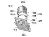
1012‧‧‧流出口 1012‧‧‧ Outflow
1014‧‧‧密封片材 1014‧‧‧sealing sheet
1016‧‧‧垂下部 1016‧‧‧Drop down
1017‧‧‧割開起端部 1017‧‧‧Cut off the end
1018‧‧‧割開終端部 1018‧‧‧Cut off the terminal
1019‧‧‧割開端緣 1019‧‧‧Cut the edge
1020‧‧‧流出口本體 1020‧‧‧Outlet body
1022‧‧‧安裝部 1022‧‧‧Installation Department
1024‧‧‧筒部 1024‧‧‧Cylinder
1026‧‧‧貫通孔 1026‧‧‧Through hole
1028‧‧‧外開口部 1028‧‧‧Outer opening
1030‧‧‧內開口部 1030‧‧‧Inner opening
1032‧‧‧右公螺紋部 1032‧‧‧Right male thread
1034‧‧‧階差部 1034‧‧‧step difference
1036‧‧‧第1凸部 1036‧‧‧The first convex part
1038‧‧‧第2凸部 1038‧‧‧The second convex part
1040‧‧‧突條 1040 ‧‧‧
1042‧‧‧旋轉停止部 1042‧‧‧rotation stop
1042a‧‧‧導引面 1042a‧‧‧Guide surface
1042b‧‧‧擋止面 1042b‧‧‧stop surface
1044‧‧‧開封體收容部 1044‧‧‧ Kaifeng Body Containment Department
1050‧‧‧開封體 1050‧‧‧ Kaifeng body
1052‧‧‧刃部 1052‧‧‧Blade
1054‧‧‧被動軸部 1054‧‧‧ Passive shaft
1056‧‧‧流出貫通孔 1056‧‧‧ Outflow through hole
1058‧‧‧入口 1058‧‧‧ entrance
1060‧‧‧出口 1060‧‧‧Export
1062‧‧‧基礎部 1062‧‧‧Basic Department
1064‧‧‧切刃部 1064‧‧‧Cutting part
1066‧‧‧切刃基底 1066‧‧‧Blade base
1068‧‧‧切刃底部 1068‧‧‧Bottom of cutting edge
1070‧‧‧刃前端部 1070‧‧‧Blade tip
1072‧‧‧刃突部 1072‧‧‧ Blade protrusion
1074‧‧‧密封片材抵接支撐部 1074‧‧‧Seal sheet abuts support
1076‧‧‧第1板狀部 1076‧‧‧The first plate
1077‧‧‧第2板狀部 1077‧‧‧The second plate
1078‧‧‧開封體本軸部 1078‧‧‧Shaft body
1079‧‧‧密封片材固定部 1079‧‧‧Seal sheet fixing part
1080‧‧‧起動體 1080‧‧‧Starter
1082‧‧‧蓋部 1082‧‧‧Cover
1084‧‧‧防止破壞部 1084‧‧‧Destruction Prevention Department
1086‧‧‧葉片按壓部 1086‧‧‧blade pressing part
1088‧‧‧右母螺紋部 1088‧‧‧Right female thread
1090‧‧‧頂部 1090‧‧‧Top
1092‧‧‧垂下部 1092‧‧‧Drop down
1098‧‧‧旋轉停止部 1098‧‧‧rotation stop
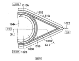
1302‧‧‧開封體收容大徑部 1302‧‧‧ Large diameter part of Kaifeng body
1304‧‧‧開封體收容小徑部 1304‧‧‧The small diameter part of the Kaifeng body
1310‧‧‧左母螺紋部/階差 1310‧‧‧Left female thread part/step difference
1310a‧‧‧左右方向延伸部 1310a‧‧‧ Extension
1310b‧‧‧上下方向延伸部 1310b‧‧‧Upward and downward extension
1310c‧‧‧下端部 1310c‧‧‧Lower end
1310d‧‧‧導引斜面 1310d‧‧‧Guide slope
1312‧‧‧旋轉停止公部 1312‧‧‧Rotation stop public office
1330,1330a,1330b,1330c‧‧‧橫肋部 1330, 1330a, 1330b, 1330c
1332‧‧‧試驗用之孔 1332‧‧‧Test hole
1340,1340a,1340b,1340c,1340d‧‧‧縱肋部 1340, 1340a, 1340b, 1340c, 1340d
1352‧‧‧大徑部 1352‧‧‧ Major Diameter Department
1354‧‧‧小徑部 1354‧‧‧ Small diameter part
1360‧‧‧左公螺紋部/階差 1360‧‧‧Left male thread part/step difference
1360a‧‧‧左右方向延伸部 1360a ‧‧‧ Extension
1360b‧‧‧立起部 1360b
1360c‧‧‧被導引斜面 1360c‧‧‧Guided slope
1360d‧‧‧上端部 1360d‧‧‧Upper end
1360e‧‧‧上下方向延伸部 1360e‧‧‧Upward and downward extension
1362‧‧‧旋轉停止母部 1362‧‧‧rotation stop female part
1370‧‧‧凸緣部 1370‧‧‧Flange
1380‧‧‧缺口部 1380‧‧‧Notch
1380a‧‧‧邊緣部 1380a‧‧‧Edge
1390‧‧‧葉片部 1390‧‧‧Blade Department
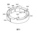
1410‧‧‧連結部 1410‧‧‧Link
1412‧‧‧上面暫時連結部 1412‧‧‧Temporary connection above
1414:側面暫時連結部 1414: Side temporary connection
1420:割開部 1420: Cutaway
1422:刃傾斜部 1422: Blade slope
1424:刃割開部 1424: Blade cut
1426:刃上下延伸部 1426: Blade up and down extension
C:中心軸 C: central axis
圖1是顯示本發明之第1實施形態之附有流出口之容器的概略立體圖。 FIG. 1 is a schematic perspective view showing a container with an outflow port according to the first embodiment of the present invention.
圖2是本發明之第1實施形態之流出口的概略立體圖解圖。 Fig. 2 is a schematic perspective view of the outlet of the first embodiment of the present invention.
圖3是本發明之第1實施形態之流出口的概略立體圖解 圖。 Fig. 3 is a schematic perspective view of the outlet of the first embodiment of the present invention Figure.
圖4A是蓋部的圖解圖,(a)為俯視圖解圖,(b)為側面圖解圖,(c)為側面圖解圖。 FIG. 4A is a diagram of the lid, (a) is a top diagram, (b) is a diagram, and (c) is a diagram.
圖4B是蓋部的圖解圖,(a)為縱截面圖解圖,(b)為頂部附近的端面圖,(c)為底面圖。 FIG. 4B is a diagram of the lid, (a) is a longitudinal sectional diagram, (b) is an end view near the top, and (c) is a bottom view.
圖5A是流出口本體的圖解圖,(a)為俯視圖解圖,(b)為正面圖解圖,(c)為側面圖解圖。 Fig. 5A is a schematic view of the outlet body, (a) is a top view, (b) is a front view, and (c) is a side view.
圖5B是流出口本體的圖解圖,(a)為縱截面圖解圖,(b)為底面圖解圖。 Fig. 5B is a diagrammatic view of the outlet body, (a) is a longitudinal cross-sectional diagram, and (b) is a bottom-surface diagram.
圖6A是開封體的圖解圖,(a)為俯視圖解圖,(b)為正面圖解圖,(c)為側面圖解圖。 FIG. 6A is a diagram of an unsealed body, (a) is a top diagram, (b) is a front diagram, and (c) is a side diagram.
圖6B是開封體的圖解圖,(a)為縱截面圖解圖,(b)為底面圖。 6B is a schematic view of an unsealed body, (a) is a longitudinal cross-sectional schematic view, and (b) is a bottom view.
圖7A是顯示本發明之第1實施形態之流出口之組裝方式的立體圖解圖。 FIG. 7A is a perspective view illustrating the method of assembling the spout in the first embodiment of the present invention.
圖7B是顯示本發明之第1實施形態之流出口之組裝方式的縱截面圖解圖。 7B is a longitudinal cross-sectional schematic diagram showing the assembly method of the outflow port according to the first embodiment of the present invention.
圖8是在本發明之第1實施形態之容器裝設流出口後的圖解圖,(a)為正面圖解圖,(b)為放大側面圖解圖。 Fig. 8 is a schematic view of a container according to a first embodiment of the present invention after an outflow port is installed, (a) is a front view, and (b) is an enlarged side view.
圖9是在本發明之第1實施形態之容器裝設流出口後的放大截面圖,(a)為側面圖解圖,(b)為(a)之H部的放大截面圖解圖,(c)為(a)的I部放大截面圖解圖。 9 is an enlarged cross-sectional view of the container according to the first embodiment of the present invention after an outflow port is installed, (a) is a schematic side view, (b) is an enlarged cross-sectional schematic view of part H of (a), (c) It is an enlarged cross-sectional diagram of part I of (a).
圖10A是將顯示本發明之第1實施形態之附有流出口之容器的使用方法之一部分放大的截面圖解圖,(a)為拿掉 擋止件之圖解圖,(b)為顯示關上蓋部之狀態的圖解圖,(c)為顯示密封片材之割開狀態的圖解圖。 10A is an enlarged cross-sectional schematic view showing a part of the method of using the container with an outflow port according to the first embodiment of the present invention, (a) is removed The diagram of the stopper, (b) is a diagram showing the state of closing the lid, and (c) is a diagram showing the cut state of the sealing sheet.
圖10B是(a)為密封片材的底面圖解圖,(b)為顯示密封片材之割開狀態的底面圖解圖,(c)為擋止件及流出口本體的橫截面圖解圖。 FIG. 10B is (a) a schematic diagram of the bottom surface of the sealing sheet, (b) a schematic diagram of the bottom surface showing the cut state of the sealing sheet, and (c) a schematic diagram of the cross section of the stopper and the outlet body.
圖11A是顯示本發明之第1實施形態之附有流出口之容器的製造方法之圖解圖,(1)是顯示第1步驟、(2)是顯示第2步驟、(3)是顯示第3步驟的圖解圖。 FIG. 11A is a diagram showing a method for manufacturing a container with an outflow port according to the first embodiment of the present invention, (1) shows the first step, (2) shows the second step, and (3) shows the third Graphical diagram of the steps.
圖11B是顯示本發明之第1實施形態之附有流出口之容器的製造方法之圖解圖,(4)是顯示第4步驟、(5)是顯示第5步驟的圖解圖。 FIG. 11B is a diagram showing a method for manufacturing a container with a spout according to the first embodiment of the present invention, (4) is a diagram showing the fourth step, and (5) is a diagram showing the fifth step.
圖11C是顯示本發明之第1實施形態之附有流出口之容器的製造方法之圖解圖,(6)是顯示第6步驟、(7)是顯示第7步驟的圖解圖。 FIG. 11C is a diagram showing a method for manufacturing a container with an outflow port according to the first embodiment of the present invention, (6) is a diagram showing the sixth step, and (7) is a diagram showing the seventh step.
圖12是顯示本發明之第2實施形態之附有流出口之容器的正面圖。 Fig. 12 is a front view showing a container with a spout according to a second embodiment of the present invention.
圖13是顯示本發明之第2實施形態之附有流出口之容器具有的流出口且可看到其底面之狀態的立體圖。 Fig. 13 is a perspective view showing a state in which the outlet port of the container with an outlet port according to the second embodiment of the present invention is visible and the bottom surface thereof can be seen.
圖14是顯示本發明之第2實施形態之附有流出口之容器具有的流出口本體之正面圖。 Fig. 14 is a front view showing an outlet body provided in a container with an outlet according to a second embodiment of the present invention.
圖15是顯示本發明之第2實施形態之附有流出口之容器具有的流出口本體,(A)為俯視圖,(B)為側面圖,(C)為底面圖。 15 is a view showing an outlet body provided in a container with an outlet according to a second embodiment of the present invention, (A) is a plan view, (B) is a side view, and (C) is a bottom view.
圖16是顯示本發明之第2實施形態之附有流出口之容 器具有的流出口本體之圖15(A)之XVI-XVI截面圖。 16 is a diagram showing the second embodiment of the present invention with the outlet The XVI-XVI cross-sectional view of FIG. 15(A) of the outlet body of the device.
圖17是顯示本發明之第2實施形態之附有流出口之容器具有的開封體之正面圖。 Fig. 17 is a front view showing the unsealed body of the container with an outflow port according to the second embodiment of the present invention.
圖18是顯示本發明之第2實施形態之附有流出口之容器具有的開封體,(A)為俯視圖,(B)為側面圖,(C)為底面圖。 Fig. 18 is a diagram showing an unsealed body of a container with a spout according to a second embodiment of the present invention, (A) is a plan view, (B) is a side view, and (C) is a bottom view.
圖19是顯示本發明之第2實施形態之附有流出口之容器具有的開封體之圖18(A)的XIX-XIX截面圖。 Fig. 19 is a XIX-XIX cross-sectional view of Fig. 18(A) showing the unsealed body included in the container with an outflow port according to the second embodiment of the present invention.
圖20是顯示本發明之第2實施形態之附有流出口之容器具有的起動體之正面圖。 Fig. 20 is a front view showing a starter included in a container with a spout according to a second embodiment of the present invention.
圖21是顯示本發明之第2實施形態之附有流出口之容器具有的起動體,(A)為俯視圖,(B)為底面圖。 Fig. 21 is a diagram showing a starter included in a container with a spout according to a second embodiment of the present invention, (A) is a plan view, and (B) is a bottom view.
圖22是顯示本發明之第2實施形態之附有流出口之容器具有的起動體,(A)為圖21(A)的XXIIA-XXIIA截面圖,(B)為圖20的XXIIB-XXIIB截面圖。 Fig. 22 is a diagram showing a starter included in a container with a spout according to a second embodiment of the present invention, (A) is a XXIIA-XXIIA cross-sectional view of Fig. 21(A), and (B) is a XXIIB-XXIIB cross-section of Fig. 20 Figure.
圖23是顯示本發明之第2實施形態之附有流出口之容器具有的起動體之防止破壞部的立體圖。 Fig. 23 is a perspective view showing a damage preventing portion of a starter body included in a container with an outflow port according to a second embodiment of the present invention.
圖24是依照本發明之第2實施形態之附有流出口之容器具有的流出口本體、開封體及起動體組裝之順序排列而從底面側觀察時的立體圖。 FIG. 24 is a perspective view when the outlet body, the unsealing body, and the starter of the container with the outlet are assembled in the order of assembly according to the second embodiment of the present invention, as viewed from the bottom surface side.
圖25是在將密封片材固定於本發明之第2實施形態之附有流出口之容器之方向排列且從底面側觀察時的立體圖。 FIG. 25 is a perspective view when the sealing sheet is fixed in the direction of the container with the outlet port according to the second embodiment of the present invention and viewed from the bottom surface side.
圖26是顯示本發明之第2實施形態之附有流出口之容 器具有的流出口之高度方向的截面圖。 26 is a view showing the second embodiment of the present invention with an outlet The cross-sectional view of the height direction of the outflow port which the device has.
圖27是顯示本發明之第2實施形態之附有流出口之容器具有的流出口,(A)為圖26的XXVII-XXVII截面圖,(B)是顯示使起動體往左旋轉時之葉片按壓部與葉片部的關係之示意圖。 Fig. 27 is a view showing an outflow port of a container with an outflow port according to a second embodiment of the present invention, (A) is a XXVII-XXVII cross-sectional view of Fig. 26, and (B) is a blade showing the starter rotating to the left A schematic diagram of the relationship between the pressing portion and the blade portion.
圖28是顯示本發明之第2實施形態之附有流出口之容器具有的流出口本體之左母螺紋部、與開封體之左公螺紋部螺合之樣子的示意展開圖,(A)顯示旋轉角度0°,(B)顯示旋轉角度150°,(C)顯示旋轉角度300°。 28 is a schematic development view showing a state in which the left female threaded portion of the outflow port body included in the container with the outflow port of the second embodiment of the present invention is screwed with the left male threaded portion of the unsealed body, (A) shows The rotation angle is 0°, (B) shows a rotation angle of 150°, and (C) shows a rotation angle of 300°.
圖29是顯示本發明之第2實施形態之附有流出口之容器具有的密封片材之一部分被割開的樣子的示意俯視圖,(A)顯示旋轉角度0°,(B)顯示旋轉角度150°,(C)顯示旋轉角度300°。 FIG. 29 is a schematic plan view showing a part of the sealing sheet of the container with an outflow port according to the second embodiment of the present invention being cut away, (A) shows a rotation angle of 0°, (B) shows a rotation angle of 150 °, (C) shows a rotation angle of 300°.
圖30是從底面側觀察本發明之第2實施形態之附有流出口之容器具有的密封片材之一部分割開的狀態時之立體圖。 Fig. 30 is a perspective view of a state where one part of the sealing sheet of the container with an outflow port according to the second embodiment of the present invention is divided from the bottom surface side.
圖31是顯示本發明之第2實施形態之附有流出口之容器具有的密封片材之一部分被割開的狀態之高度方向的截面圖。 FIG. 31 is a cross-sectional view in the height direction showing a state where a part of the sealing sheet included in the container with an outflow port according to the second embodiment of the present invention is cut.
圖32是顯示本發明之第2實施形態之流出口本體的圖19之凸緣部附近的截面圖。 32 is a cross-sectional view showing the vicinity of the flange portion of FIG. 19 of the outlet body of the second embodiment of the present invention.
圖33是顯示將本發明之第2實施形態之附有流出口之容器具有的起動體從流出口本體拆下後再次安裝時的葉片按壓部與葉片部之關係的示意圖。 Fig. 33 is a schematic diagram showing the relationship between the blade pressing portion and the blade portion when the starter included in the container with an outlet port according to the second embodiment of the present invention is removed from the outlet port body and then reinstalled.
圖34是顯示本發明之第3實施形態之附有流出口之容器的正面圖。 Fig. 34 is a front view showing a container with a spout according to a third embodiment of the present invention.
圖35是顯示本發明之第3實施形態之附有流出口之容器具有的流出口且可看到其底面之狀態的立體圖。 Fig. 35 is a perspective view showing a state in which the outlet port of the container with an outlet port according to the third embodiment of the present invention is visible and the bottom surface thereof can be seen.
圖36是顯示本發明之第3實施形態之附有流出口之容器具有的流出口本體之正面圖。 Fig. 36 is a front view showing an outlet body provided in a container with an outlet according to a third embodiment of the present invention.
圖37A是顯示本發明之第3實施形態之附有流出口之容器具有的流出口本體的俯視圖。 37A is a plan view showing an outlet body provided in a container with an outlet according to a third embodiment of the present invention.
圖37B是顯示本發明之第3實施形態之附有流出口之容器具有的流出口本體的側面圖。 37B is a side view showing an outlet body provided in a container with an outlet according to a third embodiment of the present invention.
圖37C是顯示本發明之第3實施形態之附有流出口之容器具有的流出口本體的底面圖。 37C is a bottom view showing an outlet body provided in a container with an outlet according to a third embodiment of the present invention.
圖37D是顯示將本發明之第3實施形態之附有流出口之容器具有的流出口本體與開封體組合後之狀態的底面圖。 37D is a bottom view showing a state in which the outlet body provided in the container with the outlet of the third embodiment of the present invention and the unsealing body are combined.
圖38A顯示本發明之第3實施形態之附有流出口之容器具有的流出口本體之圖37A之XXXVIIIA-XXXVIIIA截面圖。 FIG. 38A shows a cross-sectional view taken along the line XXXVIIIA-XXXVIIIA of FIG. 37A of the outlet body provided in the container with the outlet of the third embodiment of the present invention.
圖38B顯示本發明之第3實施形態之附有流出口之容器具有的流出口本體之圖37A之XXXVIIIB-XXXVIIIB截面圖。 FIG. 38B is a cross-sectional view taken along the line XXXVIIIB-XXXVIIIB of FIG. 37A of the outlet body provided in the container with the outlet according to the third embodiment of the present invention.
圖39是在可看到本發明之第3實施形態之附有流出口之容器具有的流出口本體的底面之狀態下,明示第1凸部及第2凸部的部分放大立體圖。 39 is a partially enlarged perspective view showing the first convex portion and the second convex portion in a state where the bottom surface of the spout body included in the container with the spout according to the third embodiment of the present invention can be seen.
圖40是本發明之第3實施形態之附有流出口之容器具 有的流出口本體的底面圖,且是明示第1凸部及第2凸部的部分放大立體圖。 Fig. 40 is a container with a spout according to a third embodiment of the present invention Bottom view of some spout body, and is an enlarged perspective view of a portion showing the first convex portion and the second convex portion.
圖41是沿著本發明之第3實施形態之附有流出口之容器具有的流出口本體之高度方向的截面圖,且為第1凸部及其附近的放大圖。 41 is a cross-sectional view along the height direction of the outlet body of the container with an outlet according to the third embodiment of the present invention, and is an enlarged view of the first convex portion and its vicinity.
圖42是在可看到本發明之第3實施形態之附有流出口之容器具有的開封體其底面之狀態的立體圖。 Fig. 42 is a perspective view showing the bottom surface of the unsealed body of the container with an outflow port according to the third embodiment of the present invention.
圖43是在可看到本發明之第3實施形態之附有流出口之容器具有的開封體其頂面之狀態的立體圖。 Fig. 43 is a perspective view showing the top surface of the unsealing body of the container with an outflow port according to the third embodiment of the present invention.
圖44是顯示本發明之第3實施形態之附有流出口之容器具有的開封體之正面圖。 Fig. 44 is a front view showing an unsealed body included in a container with an outflow port according to a third embodiment of the present invention.
圖45A是顯示本發明之第3實施形態之附有流出口之容器具有的開封體之俯視圖。 Fig. 45A is a plan view showing an unsealed body of a container with an outflow port according to a third embodiment of the present invention.
圖45B是顯示本發明之第3實施形態之附有流出口之容器具有的開封體之側面圖。 Fig. 45B is a side view showing the unsealed body of the container with an outflow port according to the third embodiment of the present invention.
圖45C是顯示本發明之第3實施形態之附有流出口之容器具有的開封體之底面圖。 Fig. 45C is a bottom view showing the unsealed body of the container with a spout according to the third embodiment of the present invention.
圖46是顯示本發明之第3實施形態之附有流出口之容器具有的開封體之圖45A的XLVI-XLVI截面圖。 Fig. 46 is a XLVI-XLVI cross-sectional view of Fig. 45A showing the unsealed body of the container with a spout according to the third embodiment of the present invention.
圖47是顯示本發明之第3實施形態之附有流出口之容器具有的起動體之正面圖。 Fig. 47 is a front view showing a starter included in a container with a spout according to a third embodiment of the present invention.
圖48是顯示本發明之第3實施形態之附有流出口之容器具有的起動體,(A)為俯視圖,(B)為底面圖。 Fig. 48 is a diagram showing a starter included in a container with a spout according to a third embodiment of the present invention, (A) is a plan view, and (B) is a bottom view.
圖49是顯示本發明之第3實施形態之附有流出口之容 器具有的起動體,(A)為圖48(A)的XLIXA-XLVIXA截面圖,(B)為圖47的XLIXB-XLIXB截面圖。 Fig. 49 is a diagram showing the third embodiment of the present invention with an outlet (A) is a XLIXA-XLVIXA cross-sectional view of FIG. 48(A), and (B) is a XLIXB-XLIXB cross-sectional view of FIG. 47.
圖50是顯示本發明之第3實施形態之附有流出口之容器具有的起動體之防止破壞部的立體圖。 Fig. 50 is a perspective view showing a damage preventing portion of a starter body included in a container with an outflow port according to a third embodiment of the present invention.
圖51是依照本發明之第3實施形態之附有流出口之容器具有的流出口本體、開封體及起動體組裝之順序排列而從底面側觀察時的立體圖。 Fig. 51 is a perspective view when the outlet body, the unsealing body, and the starter of the container with the outlet are assembled in the order of assembly according to the third embodiment of the present invention, as viewed from the bottom surface side.
圖52是在將密封片材固定於本發明之第3實施形態之附有流出口之容器之方向排列且從底面側觀察時的立體圖。 Fig. 52 is a perspective view when the sealing sheet is fixed in the direction of the container with the outlet port according to the third embodiment of the present invention and viewed from the bottom surface side.
圖53是顯示本發明之第3實施形態之附有流出口之容器具有的流出口之沿著高度方向的截面圖。 Fig. 53 is a cross-sectional view along the height direction showing the outflow port of the container with an outflow port according to the third embodiment of the present invention.
圖54是顯示本發明之第3實施形態之附有流出口之容器具有的流出口,(A)為圖53的LIVA-LIVA截面圖,(B)是顯示使起動體往左旋轉時之葉片按壓部與葉片部的關係之示意圖。 Fig. 54 is a view showing an outflow port of a container with an outflow port according to a third embodiment of the present invention, (A) is a LIVA-LIVA cross-sectional view of Fig. 53 and (B) is a blade showing the starter rotating to the left A schematic diagram of the relationship between the pressing portion and the blade portion.
圖55是顯示本發明之第3實施形態之附有流出口之容器具有的流出口本體之左母螺紋部、與開封體之左公螺紋部螺合之樣子的示意展開圖,(A)顯示開封體之旋轉角0°,(B)顯示開封體之旋轉角150°,(C)顯示開封體之旋轉角300°。 55 is a schematic development view showing a state in which the left female threaded portion of the outlet body of the third embodiment of the present invention and the left male threaded portion of the unsealed body are screwed together, (A) shows The rotation angle of the unsealed body is 0°, (B) shows the rotation angle of the unsealed body is 150°, and (C) shows the rotation angle of the unsealed body is 300°.
圖56是顯示在本發明之第3實施形態之附有流出口之容器具有的流出口本體之旋轉停止公部1312之高度沿著寬度方向的截面圖(圖53之LVI-LVI截面圖),(A)顯示開封體
之旋轉角0°,(B)顯示開封體之旋轉角150°,(C)顯示開封體之旋轉角300°。
56 is a cross-sectional view showing the height of the rotation stop
圖57是顯示本發明之第3實施形態之附有流出口之容器具有的密封片材之一部分被割開的樣子的示意俯視圖,(A)顯示開封體之旋轉角0°,(B)顯示開封體之旋轉角150°,(C)顯示開封體之旋轉角300°。 Fig. 57 is a schematic plan view showing a part of the sealing sheet of the container with an outflow port according to the third embodiment of the present invention being cut away, (A) shows the rotation angle of the unsealed body 0°, (B) shows The rotation angle of the unsealed body is 150°, (C) shows the rotation angle of the unsealed body is 300°.
圖58是顯示本發明之第3實施形態之附有流出口之容器具有的密封片材之一部分割開的樣子,且為沿著開封體之旋轉角150°時之高度方向的截面圖。 Fig. 58 is a cross-sectional view showing a state in which one part of a sealing sheet included in a container with a spout according to a third embodiment of the present invention is divided, and is a cross-sectional view along the height direction when the rotation angle of the unsealing body is 150°.
圖59是顯示本發明之第3實施形態之附有流出口之容器具有的密封片材之一部分割開的樣子,且為沿著開封體之旋轉角300°時之高度方向的截面圖。 Fig. 59 is a cross-sectional view showing a state where one part of the sealing sheet included in the container with an outflow port according to the third embodiment of the present invention is divided, and is a height direction along the rotation angle of 300° of the unsealing body.
圖60是顯示本發明之第3實施形態之流出口本體的圖59之凸緣部附近的截面圖。 60 is a cross-sectional view showing the vicinity of the flange portion of FIG. 59 of the outlet body of the third embodiment of the present invention.
圖61是從底面側觀察本發明之第3實施形態之附有流出口之容器具有的密封片材之一部分割開的狀態之立體圖。 Fig. 61 is a perspective view of a state where one part of the sealing sheet of the container with an outflow port according to the third embodiment of the present invention is divided from the bottom surface side.
圖62是顯示將本發明之第3實施形態之附有流出口之容器具有的起動體從流出口本體拆下後再次安裝時的圖,(A)是顯示葉片按壓部與葉片部之關係的示意圖,(B)是沿著高度方向的截面圖。 Fig. 62 is a diagram showing a starter body of a container with an outlet port according to a third embodiment of the present invention after being detached from the outlet port body and then reinstalled, (A) shows the relationship between the blade pressing portion and the blade portion Schematic diagram, (B) is a cross-sectional view along the height direction.
圖63(A)至(C)是在本發明之第3實施形態之容器裝設流出口後的放大截面圖。 63(A) to (C) are enlarged cross-sectional views after the outflow port is installed in the container of the third embodiment of the present invention.
圖64是顯示本發明之第4實施形態之附有流出口之容 器具有的開封體之立體圖。 Fig. 64 is a diagram showing a container with an outflow port according to a fourth embodiment of the present invention A perspective view of the unsealed body of the device.
圖65是顯示本發明之第4實施形態之附有流出口之容器具有的開封體之正面圖。 Fig. 65 is a front view showing an unsealed body of a container with an outflow port according to a fourth embodiment of the present invention.
圖66是顯示本發明之第4實施形態之附有流出口之容器具有的開封體,(A)為俯視圖,(B)為側面圖,(C)為底面圖。 66 is a diagram showing an unsealed body of a container with an outflow port according to a fourth embodiment of the present invention, (A) is a plan view, (B) is a side view, and (C) is a bottom view.
圖67是顯示本發明之第4實施形態之附有流出口之容器具有的開封體,(A)為圖66(C)的LXVIIA-LXVIIA截面圖,(B)為圖66(C)的LXVIIB-LXVIIB截面圖。 67 is a diagram showing an unsealed body of a container with an outflow port according to a fourth embodiment of the present invention, (A) is a LXVIIA-LXVIIA cross-sectional view of FIG. 66(C), and (B) is LXVIIB of FIG. 66(C) -LXVIIB cross-sectional view.
圖68是顯示本發明之第5實施形態之附有流出口之容器具有的開封體之立體圖。 Fig. 68 is a perspective view showing an unsealed body of a container with an outflow port according to a fifth embodiment of the present invention.
圖69是顯示本發明之第5實施形態之附有流出口之容器具有的開封體之正面圖。 Fig. 69 is a front view showing an unsealed body included in a container with an outflow port according to a fifth embodiment of the present invention.
圖70是顯示本發明之第5實施形態之附有流出口之容器具有的開封體,(A)為俯視圖,(B)為(C)的LXXB-LXXB截面圖,(C)為底面圖。 Fig. 70 is a diagram showing an unsealed body of a container with an outflow port according to a fifth embodiment of the present invention, (A) is a plan view, (B) is a LXXB-LXXB cross-sectional view of (C), and (C) is a bottom view.
圖71是可看到本發明之第5實施形態之附有流出口之容器具有的流出口之底面的狀態之立體圖。 Fig. 71 is a perspective view showing a state in which the bottom surface of the outflow port of the container with an outflow port according to the fifth embodiment of the present invention can be seen.
圖72是顯示本發明之第6實施形態之附有流出口之容器具有的起動體及開封體之正面圖。 Fig. 72 is a front view showing the starter and the unsealing body of the container with an outflow port according to the sixth embodiment of the present invention.
圖73是顯示本發明之第6實施形態之附有流出口之容器具有的起動體及開封體之底面圖。 Fig. 73 is a bottom view showing a starter body and an unsealing body of a container with an outflow port according to a sixth embodiment of the present invention.
圖74是顯示使本發明之第6實施形態之附有流出口之容器具有的流出口之起動體朝上方移動之前的狀態,(A) 是可看到底面之狀態的立體圖,(B)是沿著軸方向的截面圖。 74 is a view showing a state before the moving body of the outflow port of the container with an outflow port according to the sixth embodiment of the present invention is moved upward, (A) (B) is a cross-sectional view along the axial direction.
圖75是顯示使本發明之第6實施形態之附有流出口之容器具有的流出口之起動體朝上方移動後之狀態,(A)是可看到底面之狀態的立體圖,(B)是沿著軸方向的截面圖。 75 is a view showing a state in which the starting body of the outflow port of the container with an outflow port according to the sixth embodiment of the present invention is moved upward, (A) is a perspective view of a state where the bottom surface can be seen, (B) is A cross-sectional view along the axis.
圖76是顯示本發明之第6實施形態之附有流出口之容器具有的流出口之底面圖。 Fig. 76 is a bottom view showing an outflow port of a container with an outflow port according to a sixth embodiment of the present invention.
圖77是顯示本發明之第6實施形態之附有流出口之容器具有的流出口之變形例的底面圖,(A)顯示在仰視時呈略圓形之密封片材固定部,(B)顯示具有在仰視時呈略四角形之密封片材固定部之附有流出口之容器的變形例之底面圖。 Fig. 77 is a bottom view showing a modification of the outflow port of the container with an outflow port according to the sixth embodiment of the present invention, (A) shows the sealing sheet fixing portion having a slightly circular shape when viewed from above, (B) A bottom view showing a modified example of a container with an outflow port having a sealing sheet fixing portion having a substantially quadrangular shape when viewed from above.
圖78是本發明之附有流出口之容器的立體圖解圖。 Fig. 78 is a perspective illustration of a container with an outflow port of the present invention.
圖79是本發明之附有流出口之容器的說明圖。 Fig. 79 is an explanatory diagram of a container with an outflow port of the present invention.
參考圖式等更詳細說明關於本發明之第1實施形態之立袋型附有流出口之容器。 The vertical bag type container with an outflow port according to the first embodiment of the present invention will be described in more detail with reference to drawings and the like.
本發明人等精心檢討,結果發現:致力於覆蓋插入到容器之收容部內之流出口之內開口部的周邊區域之密封片材的鋁區域與收容部之內部的鋁區域緊密接合,藉此可達成上述目的,終完成了本發明。 The inventors of the present invention conducted a careful review and found that the aluminum area of the sealing sheet dedicated to covering the peripheral area of the inner opening of the outflow port inserted into the receiving portion of the container is tightly joined to the aluminum area inside the receiving portion, whereby Achieving the above objectives, the present invention has been completed.
附有流出口之容器10是用來裝入氫混入水之氫水者,具有裝入氫水之容器10、及安裝於容器10之流出口
12,並具有覆蓋流出口12之流出口本體20中之面臨收容部200之內開口部30的密封片材14。
The
密封片材14之鋁區域與容器10之收容部200之內表面的鋁區域之間是緊密接合的,而氫水中之氫難以從容器10及流出口本體20漏出。
The aluminum area of the sealing
流出口12具有:筒狀之流出口本體20;收納於流出口本體20之筒內的開封體50;使開封體50移動之起動體80;及用以覆蓋流出口本體20中之面臨收容部200之內開口部30的密封片材14。
The
前述開封體50是形成為不會從流出口本體20脫落,且形成為朝密封片材14移動,並且於其中央形成有流出貫通孔56。
The unsealing
前述起動體80安裝於流出口本體20之外開口部28側,且形成為使位於密封片材14側之開封體50朝密封片材14移動。
The
前述密封片材14形成為其一部分藉由開封體50被割開,而容器10之收容部200與流出口本體20之外開口部28經由開封體50之流出貫通孔56而與外部連通,並形成為容器10之收容部200內之收容物是從外開口部28朝外部流出。
The
筒狀之流出口本體20具有:具有與外部連通之貫通孔26的筒部24;挾持在構成容器10之第1容器片材210之端緣與第2容器片材220之端緣之間的安裝部22;及用以將移動體安裝成可自由螺旋轉動的公螺紋部32,前述移動體
是使自由移動地配設在筒部24之貫通孔26內的開封體50移動。
The cylindrical
前述筒部24之設置於容器10之收容部200側的安裝部22具有與開封體50之流出貫通孔56連通之入口58。
The mounting
起動體80具有蓋部82與擋止件84,且藉由將擋止件84從蓋部82分離拆下,形成移動空隙部100,並且形成為壓下開封體50以使開封體50朝密封片材14移動。
The
起動體80朝順時針方向(關閉方向)旋轉,而螺合安裝於流出口本體20之筒部24之吸口。
The
起動體80在蓋部82之內側突出設置用以壓下開封體50之按壓部86,且於蓋部82之內側設置母螺紋部88,並且藉由間隔地設置於蓋部82之下端之連結部96而連結擋止件84。
The
起動體80形成為:在周方向上將蓋部82朝開封方向(逆時針方向)轉開而從蓋部82拆下擋止件84形成移動空隙部100,並且使蓋部82朝在流出口本體20之筒部24之周方向空出的移動空隙部100移動後,按壓部86壓下開封體50。
The
開封體50在密封片材14側具有用以割開密封片材14之刃部52,且於其刃部52具有流出貫通孔56。
The unsealing
開封體50具有用以割開筒狀之滑動軸部54與密封片材14之刃部52。
The unsealing
刃部52在滑動軸部54之端部呈突緣狀伸出地連接設置於滑動軸部54。
The
刃部52形成為與設置在流出口本體20之貫通孔26之周
圍的階差部34或卡合部相接,使開封體50不會朝貫通孔26側移動。
The
密封片材14是形成為:覆蓋安裝部22之開口部地緊貼於安裝部22之容器10之收容部200側面,並與容器10之收容部200緊密接合,且,藉由被開封體50割開而流出口本體20之貫通孔26與容器10之收容部200連通。
The sealing
流出口本體20具有:安裝於構成容器10之容器片材之船形的安裝部22、及連接設置於安裝部22之上部之筒部24。
The
安裝部22及筒部24貫穿設置有貫通孔26。
The mounting
貫通孔26於安裝部22之上部具有外開口部28,且於安裝部22之下部具有內開口部30。
The through
外開口部28是在容器10朝外開口。內開口部30是朝容器10之收容部200開口。
The
流出口本體20是於筒部24之外周面環設有公螺紋部32,且,在公螺紋部32的下方,用以使起動體80停止之起動體停止部36圍繞設置於筒部24之外周面。
The
流出口本體20之起動體停止部36是突出且為具有比起動體80之蓋部82稍長之徑的圓周之突緣狀,以使在起動體80之蓋部82及擋止件84安裝於流出口本體20之安裝部22之吸口時,朝關閉方向(順時針方向)旋轉時,與螺旋轉動而下降之起動體80的擋止件84之下端卡合而使之停止。
The
起動體80具有:自由螺旋轉動地安裝於流出口本
體20之筒部24之蓋部82,及自由拆卸的連結於蓋部82之下方之擋止件84。
The
起動體80被覆於流出口本體20之外開口部28側,當使之朝關閉方向旋轉並且螺旋轉動而下降時,擋止件84之下端會接抵於起動體停止部36之上面而停止。
The
流出口本體20形成有移動限制部102,使得在拆下擋止件84時形成之移動空隙部100之高度範圍內,使起動體80之蓋部82朝下方移動停止在預定位置。
The
蓋部82具有:在俯視時呈圓形之頂部90,及從頂部90之周緣垂下而形成側壁之垂下部92。
The
蓋部82具有從頂部90之內側面在與垂下部92之間設有間隔且與垂下部92平行地垂下之按壓部86。
The
垂下部92之內周面形成有與形成於流出口本體20之筒部24之外周面之螺紋部32螺合之母螺紋部88。
On the inner peripheral surface of the hanging
按壓部86形成為:具有比拆卸擋止件84而形成之移動空隙部100之高度還短的長度,且將開封體50之滑動軸部54下壓比移動空隙部100之高度還短的長度量,使其移動停止。
The
蓋部82構成有移動限制部102,該移動限制部102是形成為:當拆卸擋止件84而下壓以割開密封片材14時,頂部90之內表面(下面)會接抵於流出口本體20之筒部24之上部,使起動體80停止在最適合的位置以割開密封片材14。
The
移動限制部102由起動體80之按壓部86及頂部90所構
成,且構成為:將開封體50下壓蓋部82之按壓部86之長度量,並且蓋部82之頂部90的下面(內表面)抵接於流出口本體20之筒部24的上部(外開口部28之側),限制開封體50之移動量。
The
擋止件84是用以限制蓋部82之螺旋轉動下降幅度者,藉由除去可使蓋部82螺旋轉動下降到預定位置。
The
圖示例中,擋止件84透過易切斷性之連結部96而上端連結到蓋部82之周壁的下面,構成圓環帶狀。
In the example shown in the figure, the
蓋部82藉由擋止件84限制螺旋轉動下降幅度而螺固於筒部24之外周。圖示例中,構成為:形成從垂下部92之上端緣在頂部90延伸設置之下端開口的有頂筒狀,且將圍繞設置於垂下部92之內周之母螺紋部88螺合於前述螺紋部32。又,從頂部90之內表面的周邊垂設用以使開封體50朝密封片材14移動之按壓部86。
The
擋止件84之上下方向(寬度方向)的長度(高度)與按壓部86之上下方向(長邊方向)的長度(高度)大略相同或較其稍長。
The length (height) of the
擋止件84之上下方向(寬度方向)的長度(高度)與下降以藉由開封體50之刃部52將密封片材14割開時之刃部52的移動間隔大略相同或較其稍長。
The length (height) and lowering of the
按壓部86之上下方向(長邊方向)的長度(高度)與下降以藉由開封體50之刃部52將密封片材14割開時之刃部52的移動間隔大略相同或較其稍長。
The length (height) and lowering of the
開封體50具有將密封片材14割開之刃部52,及突
出設置在刃部52之上部的滑動軸部54。
The unsealing
刃部52及連接設置於刃部52之上部之滑動軸部54為圓柱狀。
The
刃部52與滑動軸部54貫穿設置有流出貫通孔56。
The
流出貫通孔56具有面臨流出口本體20之外開口部28的出口60與面臨容器10之收容部200的入口58。
The outflow through
滑動軸部54形成為:可自由滑動地嵌入流出口本體20之筒部24的貫通孔26內,並且被起動體80推壓而朝下方移動。
The sliding
開封體50之滑動軸部54與流出口本體20之筒部24重疊成同心圓之雙重圓筒狀,並且可以朝上下滑動的方式自由滑動地配設在筒部24之筒內。
The sliding
起動體80之蓋部82之垂下部92與流出口本體20之筒部24配設成同心圓之雙重圓筒狀,並且以朝上下螺旋轉動的方式自由螺旋轉動地配設在筒部24之筒外。
The vertical
刃部52具有:圓柱狀之基礎部62、從基礎部62朝下方突出之切刃部64、設置於切刃部64之間之流動口66、及設置於基礎部62之周圍的停止旋轉部68。
The
刃部52具有基礎部62之高度與切刃部64之高度之和比流出口本體20之階差部34與內開口部30之間的長度相同或較其稍短的長度。
The
切刃部64分成前後,具有前面的第1切刃部70與後面的第2切刃部72。
The
第1切刃部70在仰視時呈圓弧狀,又,第2切刃部72在
以仰視時呈圓弧狀,且第1切刃部70與第2切刃部72是對向的。
The first
第1切刃部70及第2切刃部72形成為:在割開密封片材14時,一開始接觸到密封片材14之中央部左右之刃的一部分會隨著朝左右前進而其高度漸漸地變低地來割開密封片材14。
The first
而且,在以第1切刃部70割開的區域、與以第2切刃部72割開區域連接而割開的密閉片材14開口。
Then, the sealed
然而,在以第1切刃部70割開之區域、與以第2切刃部72割開之區域之間,殘留有未被割開的殘存區域,被刃部52割開之密封片材14亦可構成為被割開的周邊成為可動區域,供內容物流動。
However, between the area cut by the first
流出口本體20之筒部24在起動體停止部36之上方,環繞設置有用以限制起動體80之蓋部82及擋止件84之移動並予以保護之突條40。
The
流出口本體20之筒部24在起動體停止部36之略上方處突出設置有旋轉停止部42,旋轉停止部42是在將連結起動體80之蓋部82與擋止件84之連結部96切離時,用以僅使蓋部82旋轉而使擋止件84之旋轉停止。
The
旋轉停止部42構成為:使蓋部82朝用以關閉之關閉方向(順時針方向)旋轉時,會接抵並使擋止件84之旋轉停止。
The
起動體80之擋止件84為圓筒狀,且於其內周面突出設置有用以在切離連結起動體80之蓋部82與擋止件84之
連結部96時,僅使蓋部82旋轉而使擋止件84之旋轉停止的旋轉停止部98。
The
起動體80之旋轉停止部98構造成:朝開封方向(逆時針方向)旋轉以鬆開蓋部82時,會接抵於流出口本體20之旋轉停止部42,並且使擋止件84之旋轉停止。
The
流出口本體20之安裝部22為橫截面呈船形之柱狀體,於其中央穿設用以收容開封體50之刃部52的開封體收容部44。
The mounting
開封體收容部44是與內開口部30及貫通孔26為同心圓之圓筒狀孔。開封體收容部44在與其上方之筒部24的邊界部分的附近形成有階差部34。
The unsealed
開封體收容部44具有可裝入開封體50之刃部52之全體的容積,並且其深度具有與基礎部62之高度與切刃部64之高度之和相同或較其稍長的長度。
The unsealed
開封體收容部44之開封體50的刃部52配設成可自由上下移動。
The
安裝部22及/或筒部24形成有將開封體50之停止旋轉部68卡合或插入後阻止開封體50之旋轉的停止旋轉部68。
The
流出口本體20之停止旋轉部插入孔38構成阻止開封體50之旋轉之停止旋轉部68,且為連接設置於安裝部22之開封體收容部44之細縫狀的長溝。
The stop rotation
當開封體50嵌插於流出口本體20且開封體50之刃部52嵌插於流出口本體20之開封體收容部44時,開封體50之停
止旋轉部68插入流出口本體20之停止旋轉部插入孔38。
When the unsealing
旋轉停止部42是如圖10B(C)所示,相關於將蓋部82開封時之旋轉方向(逆時針方向),於旋轉停止部42之前側形成導引面42a,且於旋轉停止部42之後側形成有擋止面42b。導引面42a是傾斜成使蓋部82朝關閉方向旋轉時,後述之旋轉停止部98在導引面42a滑動,並且蓋部82可朝關閉方向移動的形狀。
As shown in FIG. 10B(C), the
旋轉停止部42之擋止面42b是朝流出口12之筒部24之徑方向立起的形狀。擋止面42b是使蓋部82朝開封方向旋轉時,後述之旋轉停止部98的前端會接抵於擋止面42b。
The
擋止件84具有在施加外力時可做某種程度的撓曲之可撓性。
The
蓋部82與擋止件84藉由例如聚乙烯或者聚丙烯等之合成樹脂而一體成形。
The
擋止件84經由橋狀之連結部96而與蓋部82的下端連接。
The
擋止件84透過在開封時會斷裂且寬度狹小的斷裂預定部而呈圓環狀連接。
The
如後述,在蓋部82開封之前斷裂預定部未斷裂。在蓋部82開封時,斷裂預定部會斷裂。
As described later, the portion to be broken is not broken before the
擋止件84只要由可在蓋部82之周方向上分割之複數個帶狀構件構成即可,因此亦可由例如3個以上之帶狀構件構成。
The
如圖10B(C)所示,於擋止件84之內表面,在
周方向上180°對向之部位,分別形成有一對旋轉停止部98。該等旋轉停止部98使蓋部82朝關閉方向旋轉時,可在前述旋轉停止部42之外表面滑動並朝關閉方向移動。
As shown in FIG. 10B(C), on the inner surface of the
反之,構成斜向立起的形狀,以使蓋部82朝開封方向旋轉時,旋轉停止部98之前端可接抵於旋轉停止部42之擋止面42b。
On the contrary, when the
如圖4所示,於擋止件84形成有鉤部94。鉤部94之周圍具有在蓋部82之關閉時不斷裂,在開封時會斷裂的功能。鉤部94之周邊構成有斷裂預定部。
As shown in FIG. 4, a
藉由將收容物收容於容器10之收容部200,並且將蓋部82螺旋轉入流出口12之筒部24之公螺紋部32,將流出口12之開口端(流出口本體20之外開口部28及開封體50之出口60)關閉。
By accommodating the contents in the
由於使蓋部82朝關閉方向旋轉時,擋止件84之旋轉停止部98會在流出口本體20之旋轉停止部42的導引面42a滑動,並且越過旋轉停止部42,故容許蓋部82朝關閉方向旋轉。
When the
因此,在關閉時,斷裂預定部不會斷裂,且蓋部82與擋止件84成一體,而可將蓋部82螺旋轉入到預定之關閉位置。
Therefore, when closing, the planned breaking portion will not break, and the
由擋止件84拆下蓋部82時,使蓋部82朝開封方向旋轉。如圖10B(C)所示,使蓋部82朝開封方向(逆時針方向)旋轉時,旋轉停止部98之前端會接抵於旋轉停止部42之擋止面42b,藉此可阻止擋止件84之轉動。
When the
在此狀態下,使擋止件84進而朝開封方向旋轉時,相對於停止之擋止件84,蓋部82朝開封方向相對地旋轉。
In this state, when the
在旋轉停止部98之前端接抵於擋止面42b之狀態下,當蓋部82朝開封方向旋轉時,會切離連結部96。
In a state where the end portion abuts against the
其次,當手指(指甲)扣住鉤部94,而使鉤部94之周邊的斷裂預定部斷裂時,圓環狀之鉤部94會分離而從流出口本體20之筒部24拆下。
Next, when the finger (nail) is caught by the
開封體50是在按壓斷裂薄肉斷裂線後,將斷裂之密封片材14固定於安裝部22之內開口部30之周邊,因此可防止割開之密封片材14搖晃而成為妨礙收納物之吸引等之問題,又,可省去另外丟棄密封片材14的步驟。由於藉由可撕除之擋止件84限制螺旋轉動下降幅度而使蓋部82螺固,因此只要不拆下擋止件84則無法開封,可確實地防止不小心地開封。
The unsealing
其次,針對流出口之組裝方式,主要根據圖7進行說明。 Next, the assembly method of the outflow port will be mainly described based on FIG. 7.
開封體50是使停止旋轉部68對準流出口本體20之安裝部22之停止旋轉部插入孔38,而從安裝部22之內開口部30側,插入到安裝部22及筒部24之貫通孔26之內部。
The unsealing
插入到流出口本體20之貫通孔26之內部的開封體50是作成其最下部之切刃部64不會從安裝部22之內開口部30露出到外表面的狀態。
The unsealing
接著,使密封片材14接著於安裝部22之內開口部30的周圍。
Next, the sealing
其次,使起動體80之蓋部82朝順時針方向旋轉而螺旋轉動安裝於流出口本體20之筒部24之吸口。
Next, the
起動體80之擋止件84接抵於起動體停止部36,並且起動體80在流出口本體20之預定位置停止。
The
接著,關於將流出口12安裝於容器10之方法,主要根據圖11進行說明。
Next, the method of attaching the
準備原料片(片狀物),該原料片具有:構成容器10之第1容器片材210、第2容器片材220、及連接設置於第1容器片材210與第2容器片材220之間的底部片材230。
Prepare a raw material sheet (sheet-like material) having a
原料片(片狀物)捲繞重疊成輥狀。 The raw material sheets (sheets) are wound and stacked into a roll shape.
拉出該輥狀原料片(片狀物),將底部片材230彎曲、成形為立袋之底部204,使第1容器片材210與第2容器片材220對向。
The roll-shaped raw material sheet (sheet-like material) is pulled out, and the
其次,將對向之第1容器片材210之左側緣212與第2容器片材220之左側緣222熱熔接而形成左側部206。
Next, the
第1容器片材210及第2容器片材220連接其中一側部(左側部206)與底部204。
The
在與底部204為相反側之上部的第1容器片材210之上側緣216與第2容器片材220之上側緣226之間,插入流出口12之安裝部22。
The mounting
其次,在第1容器片材210之上側緣216的內側面與第2容器片材220之上側緣226的內側面之間夾入安裝部22。
Next, the mounting
在第1容器片材210之上側緣216的內側面與第2容器片材220之上側緣226的內側面之間夾入安裝部22。
The mounting
接著,第1容器片材210之上側緣2162的內側面與第2容器片材220之上側緣226的內側面之間在其周邊區域熔接,並且夾入第1容器片材210之上側緣216的內側面與第2容器片材220之上側緣226的內側面之間的安裝部22之外周面也進行熔接。
Next, the inner side surface of the upper side edge 2162 of the
其次,令熔接之其中一側部(容器10之左側部206)為下面,使構成未熔接之側部(容器10之右側部208)之第1容器片材210的右側緣214與第2容器片材220的右側緣224為上,而在第1容器片材210與第2容器片材220之間插入用以注入收容物(氫水)之注入機的噴嘴,而將收容物(氫水)填充於容器10之流出部202。
Next, let one side of the welding (the
其次,將構成第1容器片材210之另一側部之右側緣214之內側面與構成第2容器片材220之另一側部之右側緣224之內側面在周邊進行熔接,而形成右側部208。
Next, the inner surface of the
在由上部之流出部202、左側部206、右側部208及底部204所圍繞之收容部200封入氫水。
Hydrogen water is enclosed in the
接著,收容物填充於容器10後密閉。
Next, the
複數個容器10並列而製造之容器10的連結體與和上方之容器10的左側部206鄰接之下方之容器10的右側部208連接。
The connecting body of the
將該等並列之各容器10分離時,適當地在上方之容器10的左側部206與下方之容器10的右側部208之間切斷,製造出個別的容器10。
When separating these juxtaposed
構成本發明之流出口12之材料可使用構成容器
10之塑膠膜與具有熱封性之熱塑性樹脂。
The material constituting the
如此之熱塑性樹脂可舉:例如聚丙烯、丙烯-乙烯共聚物、結晶性聚丁烯-1、結晶性聚4-甲基戊烯-1、低-、中-或者高密度聚乙烯、線形低密度聚乙烯、乙烯-醋酸乙烯酯共聚物(EVA)、乙烯-丙烯酸共聚物(EAA)、乙烯-丙烯酸乙酯共聚物(EEA)、離子交聯烯烴共聚物(離子聚合物)等之聚烯烴類;聚苯乙烯、苯乙烯-丁二烯共聚物等之芳香族乙烯基共聚物;聚氯乙烯、二氯亞乙烯樹脂等之鹵化乙烯基聚合物;如丙烯腈-苯乙烯共聚物、丙烯腈-苯乙烯-丁二烯共聚物之腈聚合物;如尼龍6、尼龍66、對或間二甲苯己二酸二醯胺之聚醯胺類;聚對苯二甲酸乙二酯、聚對苯二甲酸丁二酯、聚對苯二甲酸四亞甲酯、聚對苯二甲酸1,4-環己烷二甲酯、聚2,6萘二甲酸乙二酯等之聚酯類;各種聚碳酸酯;聚甲醛等之聚縮醛類等之熱塑性樹脂。
Examples of such thermoplastic resins include polypropylene, propylene-ethylene copolymer, crystalline polybutene-1, crystalline poly4-methylpentene-1, low-, medium- or high-density polyethylene, and linear low Polyolefins such as density polyethylene, ethylene-vinyl acetate copolymer (EVA), ethylene-acrylic acid copolymer (EAA), ethylene-ethyl acrylate copolymer (EEA), ionomer olefin copolymer (ionic polymer), etc. Class; aromatic vinyl copolymers such as polystyrene, styrene-butadiene copolymers; halogenated vinyl polymers such as polyvinyl chloride, vinylidene chloride resins; such as acrylonitrile-styrene copolymers, propylene Nitrile polymers of nitrile-styrene-butadiene copolymers; such as
特別是較佳的材料可舉例如低密度聚乙烯、線形低密度聚乙烯、中密度聚乙烯、高密度聚乙烯、聚丙烯、丙烯-乙烯共聚物等之聚烯烴樹脂。 Particularly preferred materials include polyolefin resins such as low density polyethylene, linear low density polyethylene, medium density polyethylene, high density polyethylene, polypropylene, and propylene-ethylene copolymers.
流出口本體20、開封體50及起動體80可藉由例如射出成形、壓縮成形等之公知方法成形。
The
形成於流出口本體20、開封體50及起動體80內之氣體阻隔層是由聚二氯亞乙烯樹脂、EVA皂化物、尼龍或環狀烯徑聚合物等之氣體阻隔性樹脂層、具有鋁或氧化矽等之金屬氧化物蒸鍍膜之樹脂層、含有黏土礦物之樹脂層、鋁等之金屬箔等所構成。
The gas barrier layer formed in the
氣體阻隔層可藉由例如共射出成形、多層壓縮成形、多色成形、蒸鍍等公知方法形成。 The gas barrier layer can be formed by known methods such as co-injection molding, multilayer compression molding, multi-color molding, and vapor deposition.
構成固定流出口12之容器10的塑膠膜可使用由具有熱封性之熱塑性樹脂構成之單層膜、以具有該等熱封性之熱塑性樹脂膜為袋之內層,並將其他膜積層之具有2層以上之層構成的積層膜。
The plastic film constituting the
具有熱封性之熱塑性樹脂膜可舉:例如聚丙烯、丙烯-乙烯共聚物、結晶性聚丁烯-1、結晶性聚4-甲基戊烯-1、低-、中-或者高密度聚乙烯、線形低密度聚乙烯、乙烯-醋酸乙烯酯共聚物(EVA)、乙烯-丙烯酸共聚物(EAA)、乙烯-丙烯酸乙酯共聚物(EEA)、離子交聯烯烴共聚物(離子聚合物)等之聚烯烴類;聚苯乙烯、苯乙烯-丁二烯共聚物等之芳香族乙烯基共聚物;聚氯乙烯、二氯亞乙烯樹脂等之鹵化乙烯基聚合物;如丙烯腈-苯乙烯共聚物、丙烯腈-苯乙烯-丁二烯共聚物之腈聚合物;如尼龍6、尼龍66、對或間二甲苯己二酸二醯胺之聚醯胺類;聚對苯二甲酸乙二酯、聚對苯二甲酸丁二酯、聚對苯二甲酸四亞甲酯、聚對苯二甲酸1,4-環己烷二甲酯、聚2,6萘二甲酸乙二酯等之聚酯類;各種聚碳酸酯;聚甲醛等之聚縮醛類等之熱塑性樹脂。
Examples of the thermoplastic resin film having heat sealability include polypropylene, propylene-ethylene copolymer, crystalline polybutene-1, crystalline poly4-methylpentene-1, low-, medium- or high-density polymer. Ethylene, linear low density polyethylene, ethylene-vinyl acetate copolymer (EVA), ethylene-acrylic acid copolymer (EAA), ethylene-ethyl acrylate copolymer (EEA), ionomer olefin copolymer (ionic polymer) Polyolefins such as; aromatic vinyl copolymers such as polystyrene and styrene-butadiene copolymer; halogenated vinyl polymers such as polyvinyl chloride and vinylidene chloride resin; such as acrylonitrile-styrene Copolymers, acrylonitrile-styrene-butadiene copolymers, nitrile polymers; such as
特別是較佳的材料可使用:例如低密度聚乙烯、線形低密度聚乙烯、中密度聚乙烯、高密度聚乙烯、聚丙烯、丙烯-乙烯共聚物、乙烯-醋酸乙烯酯共聚物、經乙烯系不飽和羧酸乃至其酸酐接枝改質之烯烴樹脂等之烯烴系樹脂、離子聚合物樹脂、較低融點乃至低軟化點之聚醯胺乃至共 聚醯胺樹脂、聚酯乃至共聚酯樹脂等。 Particularly preferred materials can be used: for example, low density polyethylene, linear low density polyethylene, medium density polyethylene, high density polyethylene, polypropylene, propylene-ethylene copolymer, ethylene-vinyl acetate copolymer, warp ethylene Olefin resins such as unsaturated carboxylic acids and olefin resins modified by acid anhydride grafting, ionic polymer resins, and polyamides with lower melting points or even softening points Polyamide resin, polyester and even copolyester resin.
使用積層膜作為構成容器10之塑膠膜時,可使用以具有上述之熱封性之熱塑性樹脂膜為容器10之內層,並視需要而透過接著劑層積層其他膜的積層膜。
When using a laminated film as the plastic film constituting the
形成接著劑層的材料使用選自於聚乙烯亞胺樹脂、鈦酸烷基酯、聚酯-異氰酸酯系樹脂、胺甲酸酯樹脂、環氧樹脂、聚醚系樹脂、導入極性基之烯烴系樹脂等之接著性樹脂。 The material forming the adhesive layer is selected from polyethyleneimine resins, alkyl titanate, polyester-isocyanate resins, urethane resins, epoxy resins, polyether resins, and olefin-based polar group-introduced Adhesive resin such as resin.
與熱封性樹脂積層之膜沒有特別限制,一般使用於包裝袋者皆可使用。適合如此之膜的材料,作為上述之熱封性樹脂使用之材料皆可使用,但宜選擇熔點高於使用於內層之樹脂的樹脂。 The film laminated with the heat-sealable resin is not particularly limited, and can generally be used by those who use it in packaging bags. The material suitable for such a film can be used as the above-mentioned heat-sealable resin, but it is preferable to select a resin having a melting point higher than that of the resin used in the inner layer.
又,構成容器10之收容部200之區域的膜使用將鋁等之金屬箔與上述之塑膠膜之1種或2種以上貼合者。特別是,為氫水的情況時,宜使用包含鋁等之金屬箔的積層膜。其他亦可為聚二氯亞乙烯樹脂、EVA皂化物、尼龍或環狀烯徑聚合物等之樹脂層、具有鋁或氧化矽等之金屬氧化物蒸鍍膜的樹脂層、含有黏土礦物之樹脂層。
In addition, for the film constituting the area of the
以下,關於該發明之第2實施形態之附有流出口之容器10,參考圖12至32進行說明。圖12是顯示本發明之第2實施形態之附有流出口之容器的正面圖。圖13是顯示本發明之第2實施形態之附有流出口之容器具有的流出口之觀察其底面之狀態的立體圖。
Hereinafter, the
該實施形態之附有流出口之容器10具有:裝
入氫水之容器10;及安裝於容器10之流出口本體1020,更具有覆蓋面臨流出口本體1020之收容部200之內開口部1030的密封片材1014。密封片材14之鋁區域與容器10之收容部200之內表面之鋁區域之間是緊密接合的,氫水中之氫難以從容器10及流出口本體20洩漏。該實施形態之附有流出口之容器10具有用以讓收容於容器10之氫水朝外部流出之流出口1012。流出口1012包含:流出口1020、開封體1050、及起動體1080。密封片材1014固定於流出口本體1020之底面。開封體1050構造成:插入形成於流出口本體1020之貫通孔1026,並朝上下方向(軸方向)移動,並形成為可割開密封片材1014之一部分。起動體1080構造成:螺固於形成在流出口本體1020之貫通孔1026的外開口部1028而密閉容器10,並且在流出時開封,且使開封體1050朝上下方向移動。
The
關於該實施形態之附有流出口之容器10具有之流出口本體,根據圖14至16進行說明。圖14是顯示本發明之第2實施形態之附有流出口之容器具有的流出口本體之正面圖。圖15是顯示本發明之第2實施形態之附有流出口之容器具有的流出口本體,(A)為俯視圖,(B)為側面圖,(C)為底面圖。圖16是顯示本發明之第2實施形態之附有流出口之容器具有的流出口本體之圖15(A)之XVI-XVI截面圖。
The outlet body provided in the
流出口本體1020具有:安裝於容器10之安裝部1022;及筒部1024,在安裝部1022之頂部上面之略中央,朝上方突出設置,並且成為將開封體1050插入氫水流出時
之吸口的部位。安裝部1022、與筒部1024是以例如合成樹脂等之材料一體成形。在流出口本體1020形成朝上下方向貫通其略中央、即從安裝部1020之底面含括貫通到筒部1024之上面且在俯視時呈略圓形之貫通孔1026。貫通孔1026具有:形成於安裝部1020之底面之內開口部1030、及形成於筒部1024之上面之外開口部28。
The
安裝部1022以挾持於構成容器10之第1容器片材1210的端緣、及第2容器片材1220的端緣之間的方式安裝於容器10。安裝部1022具有:在俯視之為略菱形之底部、從底部之端緣立起的側部、及具有與底部大略相同之形狀的頂部。3個橫肋部1330a、1330b、1330c與3個縱肋部1340a、1340b、1340c突出設置於安裝部1022之其中一側的側部。3個橫肋部1330a、1330b、1330c在左右方向(橫向)上呈直線狀延伸。又,3個橫肋部1330a、1330b、1330c互相平行,且在上下方向以等間隔設置。在橫肋部1330b之略中央形成朝寬度方向貫通到上述之貫通孔1026且在俯視時呈略圓形之試驗用的孔1332。
The
3個縱肋部1340a、1340b、1340c在上下方向(縱向)上呈直線狀延伸。3個縱肋部1340a、1340b、1340c是互相平行,且在左右方向上以等間隔設置。再者,安裝部1022之另一側的側部除了未形成有試驗用之孔1332之外,與其中一側之側部相同的構成,因此在此不重複相同的說明。
The three
試驗用之孔1332設置用以在組裝流出口1012後,
插進專用之噴嘴而注入空氣,測定氣壓變化,藉此,可確認藉由密封片材1014是否確實地密閉形成於開封體1050之流出貫通孔1056的入口1058(形成於流出口本體1020之貫通孔1026的內開口部1030),及藉由起動體1080是否確實地密閉流出貫通孔1056的出口1060(貫通孔1026的外開口部1028)。
The
在安裝部1022之略中央,如上所述,形成在俯視時呈略圓形之貫通孔1024。形成於安裝部1022之貫通孔1024形成成為用以收容開封體1050之刃部1052之空間。將該空間作為開封體收容部1044。在開封體收容部1044之內壁(即,貫通孔1026之側壁下部),形成左母螺紋部1310(第2母螺紋部),該左母螺紋部1310是構成當朝俯視左旋轉(逆時針方向)擰緊時(旋回時)行進之螺紋(以下,稱為「左螺紋」)之母部。左母螺紋部1310之下端部(即,左母螺紋之終端部)位於比貫通孔1026之內開口部1030略上方。而且,在該終端部的附近,朝下方(第2方向)突出設置在側視時呈略四角形之旋轉停止公部1312,該旋轉停止公部1312用以使開封體1050之俯視的旋轉運動(俯視往左旋轉及往右旋轉)停止,並且使開封體1050一面旋轉一面上下移動的情況停止。旋轉停止公部1312之側面視圖為略四角形。
At the approximate center of the mounting
筒部1024具有成為吸口之徑及可螺嵌於起動體1080之長度的略圓筒形狀。在筒部1024之外表面突出設置右公螺紋部1032(第1公螺紋部)、突條1040、及旋轉停止
部1042。
The
右公螺紋部1032形成於筒部1024之外表面上部,構成以俯視往右旋轉(順時針方向)擰緊時(旋回時)行進之螺紋(以下,稱為「右螺紋」)之公部。突條1040在右公螺紋部1032之下部,含括筒部1024之外表面全周設置。突條1040之其徑方向的尺寸為從上端朝下端變大之形狀。即,突條1040具有從上端向下端傾斜之形狀。旋轉停止部1042在突條1040之下部,於周方向上以等間隔設置4個。
The right
旋轉停止部1042分別具有導引面1042a、及擋止面1042b。以俯視向右(順時針方向)看筒部1024時,導引面1042a成為先出現的面,擋止面1042b成為後出現的面。導引面1042a以俯視往右旋轉(順時針方向)來看,傾斜成從先出現之端緣朝向後出現之端緣,徑方向之尺寸變大。另一方面,擋止面1042b為朝筒部1024之徑方向延伸的形狀。即,旋轉停止部1042分別為俯視呈略直角三角形。
The
關於該實施形態之附有流出口之容器10之具有的開封體,根據圖17至19進行說明。圖17是顯示本發明之第2實施形態之附有流出口之容器具有的開封體之正面圖。圖18是顯示本發明之第2實施形態之附有流出口之容器具有的開封體,(A)為俯視圖,(B)為側面圖,(C)為底面圖。圖19是顯示本發明之第2實施形態之附有流出口之容器具有的開封體之圖18(A)的XIX-XIX截面圖。
The opening body of the
開封體1050形成為在流出口本體1020之貫通孔1026的內部朝下方移動,而不會從流出口本體1020脫落。
開封體1050具有:刃部1052、及突出設置於刃部1052之頂部上面的略中央之被動軸部1054。刃部1052、被動軸部1054之間是以例如合成樹脂等之材料一體成形。開封體1050之上下方向的尺寸(即,刃部1052與被動軸部1054之上下方向的尺寸之和)比流出口本體1020之尺寸略小。於開封體1050形成在上下方向貫通其略中央、即從刃部1052之底面貫通到被動軸部1054之上面之俯視呈略圓形之流出貫通孔1056。流出貫通孔1056具有:形成於刃部1052之底面之入口1058、及形成於被動軸部1054之上面之出口1060。
The
刃部1052為略圓筒形。刃部1052是其外徑與形成於流出口本體1020之開封體收容部1044的內徑大略相等或較小。又,刃部1052是其上下方向的尺寸與形成於流出口本體1020之開封體收容部1044的內徑大略相等或較小。
The
刃部1052形成為從下端部愈朝上方則其徑方向之尺寸則愈大。刃部1052具有從其上端部到下端部附近之基礎部1062、及形成於其下端部之切刃部1064。在基礎部1062之外表面,形成構成左螺紋之公部之左公螺紋部1360(第2公螺紋部)。該左公螺紋部1360螺合於形成於上述流出口本體1020之內表面的左母螺紋部1310。在左母螺紋部1310之起端部的附近形成旋轉停止母部1362而成為在側視時呈略四角形凹入。該旋轉停止母部1362與形成於上述之左母螺紋部1310之終端部的旋轉停止公部1312協同作動而作用。關於該協同作動之態樣的詳情於後敘述。在基礎部1062之左公螺紋部1310的下部,凸緣部1370含括全周形成徑方向之
尺寸變小的階差。切刃部1064形成為徑方向之尺寸從其上端部朝下端部變小。於切刃部1064形成從其下端部到上端部延伸之側視略呈四角形狀之缺口部1380。缺口部1380俯視時,是形成於與在上述之左公螺紋部1310之起端部附近形成之旋轉停止公部1362偏離約300°的位置。再者,缺口部1380宜為下底的長度尺寸比上底的長度尺寸略大,且下底之兩端的內角形成為彼此相等的梯形。
The
被動軸部1054是其上下方向的尺寸為比流出口本體1020之筒部1024的上下方向尺寸略小之略圓筒形狀。在被動軸部1054之外表面,突出設置有從其上端部到下端部在上下方向延伸之作為被動部的3個葉片部1390。葉片部1390分別具有彼此相同的形狀,並且在被動軸部1054之周方向上以等間隔形成。被動軸部1054在俯視觀察時,連結3個葉片部1390之前端時描繪出之圓的直徑(即,被動軸部1054之包含葉片部1390的外徑)與流出口本體1020之筒部1024的內徑大略相等或較小。葉片部1390具有用以與起動體1080往左旋轉(逆時針方向)連動而開封體1050也往左旋轉的構成。葉片部1390分別形成為在俯視時,以往左旋轉(逆時針方向)來看,先出現之面突出的方向與被動軸部1054之外表面的切線方向構成的角度,小於以往左旋轉來看後出現之面突出之方向與被動軸部1054之外表面的切線方向構成的角度。即,葉片部1390分別在俯視時,以往左旋轉來看時,傾斜成從其基底(即,被動軸部1054與外表面的連接部)朝其前端後退。再者,被動軸部1054之外
表面宜形成為從其上端部朝下端部,徑方向之尺寸會略小。
The
就該實施形態之附有流出口之容器10之具有的起動體,根據圖20至23進行說明。圖20是顯示本發明之第2實施形態之附有流出口之容器具有的起動體之正面圖。圖21是顯示本發明之第2實施形態之附有流出口之容器具有的起動體,(A)為俯視圖,(B)為底面圖。圖22是顯示本發明之第2實施形態之附有流出口之容器具有的起動體,(A)為圖21(A)的XXIIA-XXIIA截面圖,(B)為圖20的XXIIB-XXIIB截面圖。圖23是顯示本發明之第2實施形態之附有流出口之容器具有的起動體之防止破壞部的立體圖。
The starter included in the
起動體1080形成為可拆卸地螺合於流出口本體1020之軸方向的其中一端部,且可使開封體1050在流出口本體1020之貫通孔1026的內部朝下方移動。起動體1080包含:蓋部1082、及用以使初期狀態之蓋部1082被破壞的情況明確化之防止破壞部1084。
The
蓋部1082包含:俯視時呈略圓形之頂部1090、及為從頂部1090之端緣垂下之側壁的垂下部1092。即,蓋部1082為其底面具有開口之略圓柱形狀。頂部1090與垂下部1092是以合成樹脂一體成形。蓋部1082之內徑與流出口本體之1020之筒部1024之外徑大略相等或較大。又,蓋部1082是其上下方向的尺寸與從流出口本體1020之上端部到突條1040之尺寸大略相等。在頂部1090之內表面配設朝與垂下部1092相同之方向垂下且作為3個作動部之葉片按壓部
1086。在垂下部1092之內表面形成構成右螺紋之母部之右母螺紋部1088(第1母螺紋部)。3個葉片按壓部1088分別具有同樣的形狀。又,3個葉片按壓部1088分別形成為在俯視時,呈略圓弧狀。又,3個葉片按壓部1088分別配設成在俯視時彼此連結時描繪出一個圓。又,3個葉片按壓部1088分別以俯視往左旋轉來看,宜形成後出現之端部之徑方向的尺寸比先出現之端部之徑方向的尺寸略大。該右母螺紋部1088螺合於形成於上述之流出口本體1020外表面的右公螺紋部1032。
The
防止破壞部1084是其內徑及外徑形成為與蓋部1082之內徑及外徑大致相同的圓環狀。又,防止破壞部1084是其高度方向之尺寸與流出口本體1020之旋轉停止部1042之高度方向的尺寸大致相同。防止破壞部1084於其上面突出設置2個連結部1410及4個上面暫時連結部1412,且於其側壁之外表面突出設置4個側面暫時連結部1414,於其側壁之內表面突出設置旋轉停止部1098。起動體1080在剛出貨時的初期狀態(即,在密封片材1014固定於流出口本體1020、開封體1050及起動體1080組裝而成之流出口1012之底面的狀態下,將流出口1012安裝於在其收容部200收容氫水之容器10之端緣而密封的狀態)下,其蓋部1082之下端部與其防止破壞部1084之2個連結部1410各自之前端部及4個上面暫時連結部1412各自之前端部是連結的。又,防止破壞部1084在初期狀態中,是藉由4個側面暫時連結部1414,含括其全周而連結。2個連結部1410是側視時呈略L字形。又,4
個上面暫時連結部1412及4個側面暫時連結部1414的連結構成為容易斷裂。該旋轉停止部1098與上述之旋轉停止部1042協同作動作用。該協同作動態樣之詳情於後述。
The
接著,就組裝流出口1012之步驟之一例,根據圖24至26進行說明。圖24是依照本發明之第2實施形態之附有流出口之容器具有的流出口本體、開封體及起動體組裝之順序排列而從底面側觀察時的立體圖。圖25是在將密封片材固定於本發明之第2實施形態之附有流出口之容器之方向排列且從底面側觀察時的立體圖。圖26是顯示本發明之第2實施形態之附有流出口之容器具有的流出口之沿著高度方向的截面圖。
Next, an example of the procedure for assembling the
首先,將起動體1080從流出口本體1020之上面側(筒部1024之上面側)嵌進去,以形成為俯視時,起動體1080之中心與流出口本體1020之筒部1024之中心為同心。
First, the
如此,形成於流出口本體1020之上部(筒部1024)之外表面之右公螺紋部1032的上端部(即,右公螺紋部1032的終端部)接抵於形成於起動體1080之內表面之右母螺紋部1088的下端部(即,右母螺紋部1088的起端部)。
In this way, the upper end portion of the right male screw portion 1032 (that is, the end portion of the right male screw portion 1032) formed on the outer surface of the upper portion (tube portion 1024) of the
由此,藉由將起動體1080以俯視往右旋轉(順時針方向),使右母螺紋部1088與右公螺紋部1032螺合。如此,起動體1080往流出口本體1020之下方行進。
Thus, by rotating the
當使右母螺紋部1088與右公螺紋部1032持續螺合,並且使起動體1080持續往下方行進時,突出設置於防止破壞部1084之側壁之內表面的旋轉停止部1098抵接於突
出設置在流出口本體1020之外表面之旋轉停止部1042的導引面1042a。在此,如上所述,導引面1042a是傾斜成以俯視往右(順向)旋轉(順時針方向)來看流出口本體1020時,徑方向之尺寸從先出現之端緣朝後出現之端緣變大。流出口本體1020之旋轉停止部1042具有如此的形狀,藉此防止破壞部1084之旋轉停止部1098容易越過流出口本體1020之旋轉停止部1042之導引面1042。因此,防止破壞部1084(起動體1080)可繼續往右旋轉(順時針方向)。
When the right female threaded
使起動體1080往右旋轉(順時針方向),朝下方行進,直到起動體1080之頂部1090之內表面與流出口本體1020之上端抵接或幾乎抵接。將起動體1080螺合到最後時,蓋部1082之下端部位於流出口本體1020之突條1040之上部附近,防止破壞部1084位於與流出口本體1020之旋轉停止部1042大致相同的高度。即,蓋部1082之垂下部1092之內表面與流出口本體1020之突條1040較上部之外表面對向,且防止破壞部1084之內表面與流出口本體1020之旋轉停止部1042之外表面對向。如此,使起動體1080螺合於流出口本體1020之上部。
The
其次,從流出口本體1020之貫通孔1026之內開口部1030側(即,流出口本體1020之底面側)插入開封體1050,以形成為俯視時,流出口本體1020之開封體收容部1044之中心與開封體1050之中心為同心。此時,將開封體1050從其被動軸部1054之上端部插入到貫通孔1050。
Next, the unsealing
此時,以形成於流出口本體1020之旋轉停止公部
1312在俯視時,會位於與形成於開封體1050之旋轉停止母部1362偏離約300°的位置的方式,將開封體1050插入流出口本體1020之貫通孔1026。此時,形成於流出口本體1020之旋轉停止公部1312位於與形成於開封體1050之缺口部1360大致相同的位置。
At this time, the male part is stopped by the rotation formed in the
將開封體1050插入流出口本體1020之貫通孔1050,直到形成於開封體1050之左母螺紋部1310接抵於流出口本體1020之旋轉停止公部1312之前端部時,開封體1050之刃部1052完全地收容於流出口本體1020之開封體收容部1044。此時,刃部1052之上面與開封體收容部1044之上壁相接或是彼此位於附近,且刃部1052之底面(即,開封體1050之底面)與開封體收容部1044之底面(即,流出口本體1020之底面)成為大致相同的高度。又,此時,開封體1050是其被動軸部1054在流出口本體1020之筒部1024之內部(即,貫通孔1026之開封體收容部1044較上部)延伸。再者,在俯視時,開封體1050之被動軸部1054之中心與流出口本體1020之筒部1024之中心為同心。進而,此時,突出設置於開封體1050之被動軸部1054之外表面的3個葉片部1390之以俯視往左旋轉(逆時針方向)來看而先出現之面,與從起動體1080之頂部1090朝下方延伸地形成之3個葉片按壓部1086各自之以俯視往左旋轉(逆時針方向)來看而先出現之端部對向。
Insert the unsealing
如上述,起動體1080螺合於流出口本體1020之上部,並將開封體1050插入流出口本體1020之貫通孔1026,
藉此來組裝流出口1012。而且,在流出口1012之底面(即,流出口本體1020之底面)固定密封片材1014。此時,將密封片材1014固定成使貫通孔1026之內開口部1030密閉。再者,就密封片材1014之構成,由於與上述之實施形態相同,因此在此不重複相同的說明。而且,將其底面固定有密封片材1014之流出口1012安裝於容器10。如此所得到的附有流出口之容器10藉由密封片材1014,遮蔽了容器10之收容部200、與形成於流出口1012之貫通孔1026。因此,可防止收容於容器10之收容部200之氫從安裝部1022及流出口1012之貫通孔1026漏出。
As described above, the
接著,就作成藉由將密封片材1014之一部分割開,使容器10之收容部200、與形成於流出口1012之貫通孔1026連通,並可飲用氫水之狀態之態樣的一例,根據圖27至32來進行說明。圖27是顯示本發明之第2實施形態之附有流出口之容器具有的流出口,(A)為圖26的XXVII-XXVII截面圖,(B)是顯示使起動體往左旋轉時之葉片按壓部與葉片部的關係之示意圖。圖28是顯示本發明之第2實施形態之附有流出口之容器具有的流出口本體之左母螺紋部、與開封體之左公螺紋部螺合之樣子的示意展開圖,(A)顯示旋轉角度0°,(B)顯示旋轉角度150°,(C)顯示旋轉角度300°。圖29是顯示本發明之第2實施形態之附有流出口之容器具有的密封片材之一部分被割開的樣子的示意俯視圖,(A)顯示旋轉角度0°,(B)顯示旋轉角度150°,(C)顯示旋轉角度300°。圖30是從底面側觀察本發明之第2實施形態之附
有流出口之容器具有的密封片材之一部分割開的狀態時之立體圖。圖31是顯示本發明之第2實施形態之附有流出口之容器具有的密封片材之一部分被割開的狀態之高度方向的截面圖。圖32是顯示本發明之第2實施形態之流出口本體的圖19之凸緣部附近的截面圖。
Next, an example of a state in which the
抓住其垂下部1092而使起動體1080俯視往左旋轉(逆時針方向),(朝連通旋轉方向旋轉,)使起動體1080朝上方(第1方向)移動。藉此,防止破壞部1084之4個上面暫時連結部1412與蓋部1082之下端部之連結會斷裂。又,與此同時,突出設置於防止破壞部1084之側壁的旋轉停止部1098作成與突出設置於流出口本體1020之外表面的旋轉停止部1042之擋止面1042b抵接,形成欲越過該處之狀態。此時,防止破壞部1084之內徑被流出口本體1020之旋轉停止部1042推展開,因此在周方向上暫時連結防止破壞部1084之4個側面暫時連結部1414也會斷裂。再者,防止破壞部1084之俯視呈略L字形之2個連結部1410保持朝防止破壞部1084之內徑擴展的方向撓曲,並且與蓋部1082之下端部連結之狀態。
Holding the hanging
防止破壞部1084之上面暫時連結部1412及側面暫時連結部1414之連結一斷裂,就能使密閉的蓋部1082被破壞的情況予以明確化。藉此,可確保安全性。進而,防止破壞部1084是即使上面暫時連結部1412及側面暫時連結部1414之連結斷裂,也可保持連結部1410與蓋部1082之下端部連結的狀態。即,蓋部1082與防止破壞部1084是藉由
轉合部1410而為經常連結之狀態,因此在開關流出口1012時之使用方便性變良好。
As soon as the connection between the upper
如上所述,藉由使起動體1080以俯視往左旋轉(逆時針方向),並且朝上方(第1方向)移動,而將防止破壞部1084之上面暫時連結部1412及側面暫時連結部1414的連結斷裂。與此同時,從起動體1080之頂部1090朝下方延伸而形成之3個葉片按壓部1086各自之以俯視往左旋轉(逆時針方向)來看先出現之端部,抵接於突出設置在開封體1050之被動軸部1054之外表面之3個葉片部1390之以往左旋轉(逆時針方向)來看先出現之面,並一面滑動一面推進。藉此,使插入到流出口本體1020之開封體1050也以俯視往左旋轉(逆時針方向)。
As described above, by rotating the
開封體1050以俯視往左旋轉(逆時針方向)時,形成於其外表面下部之公螺紋部1360會被導向而螺旋前進到形成於流出口本體1020之內壁的左母螺紋部1310,往下方(第2方向)行進。即,開封體1050朝與起動體1080移動之上方向(第1方向)相反的下方向(第2方向)移動。
When the
開封體1050在初期狀態中,其底面之高度與流出口本體1020之底面之高度(即,貫通孔1026之內開口部1030之高度)相同或大致相同。開封體1050從該初期狀態藉由俯視往左旋轉(逆時針方向)而漸朝下方移動時,形成於其下端之刃部1052會從流出口本體1020之底面突出。此時,形成於刃部1052之下端部之缺口部1380會一面旋轉一面畫圓地割開固定於流出口本體1020之底面的密封片材1014。
In the initial state, the height of the bottom surface of the unsealed
圖28及圖29顯示此時之作動態樣的示意圖。 28 and 29 show schematic diagrams of the dynamic samples at this time.
開封體1050從初期狀態往左旋轉(逆時針方向)300°時,開封體1050往下方移動,藉此葉片按壓部1086與葉片部1390變得不相接,開封體1050之旋轉停止,並且形成於流出口本體1020之左母螺紋部1310之起端部附近的旋轉停止公部1312嵌合於形成於其左公螺紋部1360之終端部附近的旋轉停止母部1362。藉此,開封體1050在從初期狀態往左旋轉(逆時針方向)300°之狀態下,其旋轉受限制,變得也無法往上下方向移動。如此,藉由使開封體1050左旋轉(逆時針方向)300°,密封片材1014之一部分被割開,容器10之收容部200、與開封體1050之注出貫通孔1056(及流出口本體1020之貫通孔1026)連通。再者,密封片材1014如上所述,只割開300°。即,由於密封片材1014之剩餘60°的部分還連接著其他部分,因此圓狀之切屑成為垂下到密封片材1014之其他部分的狀態。因此,由於切屑不會落下到容器10之收容部200,故可防止誤飲切屑的情況。再者,上述中,是就使開封體1050左旋轉300°作說明,但不限於此種情況,亦可藉由旋轉小於360°之其他角度,成為密封片材1014之切開的部分、與其他部分連接的狀態。
When the
刃部1052形成為從下端部愈朝向上方則其徑方向之尺寸愈大。因此,密封片材1014之其呈圓狀切開之部分之部分之徑方向的尺寸是開封體1050愈朝下方前進,則與推開刃部1052之外表面而漸漸變大。接著,開封體1050左旋轉(逆時針方向)300°後,成為開封體1050之凸緣部1370
的底面載置於密封片材1014之上面(內表面)之呈圓狀切開之部分的外緣部的狀態。藉此,可防止開封體1050落下到容器10之收容部200。
The
如上所述,藉由使起動體1080往俯視左旋轉(逆時針方向),起動體1080朝上方移動。藉此,當防止破壞部1084之暫時連結遭到斷裂,使密閉之蓋部1082被破壞得予以明確化。又,與此同時,開封體1080一面朝俯視左旋轉(逆時針方向)一面朝下方移動。藉此,密封片材1014之一部分切開,容器10之收容部200與流出口本體1020之貫通孔1026(開封體1050之注出貫通孔1056)連通。此時為使起動體1080左旋轉(逆時針方向)約300°後之狀態。若從此狀態使起動體1080在朝俯視左旋轉(逆時針方向),使起動體1080朝上方移動,開放形成於起動體1080之內表面的右母螺紋部1088、與形成於流出口本體1020之外表面的右公螺紋部1032的螺合狀態,從流出口本體1020拆下起動體1080。如此,開放形成於開封體1050之流出貫通孔1056之出口(及形成於流出口本體1020之外開口部1028)。
As described above, by rotating the
再者,由流出口本體1020拆下起動體1080後,藉由再次安裝,可塞住形成於流出口本體1020之貫通孔1026之外開口部1028(形成於被動軸部1054之流出貫通孔1056之出口1060),防止氫水由容器10之收容部200朝外部漏出。由於將起動體1080安裝於流出口本體1020,因此藉由覆蓋流出口本體1020之上端部,並使之俯視右旋轉以螺合時,形成於起動體1080之3個葉片部1390的下端部會接抵於插
入貫通孔1026之被動軸部1054之葉片按壓部1086的上端部。
Furthermore, after the starting
圖33是顯示將本發明之第2實施形態之附有流出口之容器具備之起動體從流出口本體拆下後,再次安裝時之葉片按壓部與葉片部的關係之示意圖。在此,如上所述,形成於起動體1080之3個葉片部1390分別俯視時形成為:以左旋轉(逆時針方向)來看先出現之面突出之方向與被動軸部1054之外表面之切線方向所呈角度比以左旋轉來看後出現之面突出之方向與被動軸部1054之外表面之切線方向所呈角度還小。又,如上所述,形成於起動體1080之3個葉片按壓部1088分別往俯視左旋轉看時,後出現之端部之徑方向的尺寸形成比先出現之端部還大。葉片部1390及葉片按壓部1086具有如此的形狀,藉此將起動體1080安裝完成時會彼此干擾時,會彼此變形而鬆開。
FIG. 33 is a schematic diagram showing the relationship between the blade pressing portion and the blade portion when the starter provided in the container with the outlet port according to the second embodiment of the present invention is removed from the outlet port body and then reinstalled. Here, as described above, the three
該實施形態之附有流出口之容器10是如上所述,可知僅以使起動體1080從初期狀態往俯視左旋轉(逆時針方向)而從流出口本體1020拆下,即可破壞密閉之蓋部1082,且容器10之收容部200與流出口本體1020之貫通孔1026(開封體1050之流出貫通孔1056)連通,成為可飲用氫水之狀態。因此,由於不需要用以割開密封片材1014之特別的手續,可提供一種使用方便性良好的附有流出口之容器10。
The
再者,上述之實施形態中,已就第1公螺紋部及第1母螺紋部是右螺紋(右公螺紋部1032、右母螺紋部1088),第2公螺紋部及第2母螺紋部是左螺紋(左公螺紋部1360、
左母螺紋部1310)的情況作說明。然而,並不限於此種情況,亦可為第1公螺紋部及第1母螺紋部為左螺紋,第2公螺紋部及第2母螺紋部為右螺紋。
Furthermore, in the above-mentioned embodiment, the first male thread portion and the first female thread portion are right threads (right
(第3實施形態之附有流出口之容器10)
(Container with
以下,參照圖34~63說明本發明之第3實施形態之附有流出口之容器10。圖34是顯示本發明之第3實施形態之附有流出口之容器的正面圖。圖35是顯示本發明之第3實施形態之附有流出口之容器具有的流出口且可看到其底面之狀態的立體圖。
Hereinafter, the
該實施形態之附有流出口之容器10具有:可放入氫水之容器10、及安裝於容器10之流出口本體1020,更具有用以覆蓋面臨流出口本體1020之收容部200之內開口部1030的密封片材1014。
The container with an
構成密封片材1014之鋁片與流出口本體1020之底面大略相同大小。
The aluminum sheet constituting the
密封片材1014之鋁區域與容器10之收容部200之內面之鋁區域之間是密接的,氫水中之氫難以從容器10及流出口本體1020洩出。
The aluminum area of the
該實施形態之附有流出口之容器10具有用以將收容於容器10之氫水朝外部流出之流出口1012。
The
再者,附有流出口之容器10可收容之氫水的容量可為150ml、300ml或500ml等,但沒有特別限定。
In addition, the volume of hydrogen water that can be accommodated in the
(流出口1012) (Outlet 1012)
流出口1012包含:流出口本體1020、開封體1050、及
起動體1080。密封片材1014固定於流出口本體1020之底面。開封體1050構造成:插入形成於流出口本體1020之貫通孔1026,並朝上下方向(軸方向)移動,並形成為可割開密封片材1014之一部分。
The
起動體1080構造成:螺固於形成在流出口本體1020之貫通孔1026的外開口部1028而密閉容器10,並且在流出時開封,且使開封體1050朝密封片材1014之方向移動。
The
(流出口本體1020) (Outlet body 1020)
根據圖36~41說明該實施形態之附有流出口之容器10具有之流出口本體。圖36是顯示本發明之第3實施形態之附有流出口之容器具有之流出口本體的正面圖。圖37A是顯示本發明之第3實施形態之附有流出口之容器具有之流出口本體的俯視圖。圖37B是顯示本發明之第3實施形態之附有流出口之容器具有之流出口本體的側面圖。圖37C是顯示本發明之第3實施形態之附有流出口之容器具有之流出口本體的底面圖。圖37D是顯示本發明之第3實施形態之附有流出口之容器具有之流出口本體與開封體組合後之狀態的底面圖。圖38A是顯示於本發明之第3實施形態之附有流出口之容器具有之流出口本體之圖37A的XXXVIIIA-XXXVIIIA截面圖。圖38B是顯示於本發明之第3實施形態之附有流出口之容器具有之流出口本體之圖37A的XXXVIIIB-XXXVIIIB截面圖。圖39是在可看到本發明之第3實施形態之附有流出口之容器具有之流出口本體之底面的狀態下,明示第1凸部及第2凸部之立體部分放圖。圖40是本發明之
第3實施形態之附有流出口之容器具有之流出口本體之底面圖,且是明示第1凸部及第2凸部之部分放大圖。圖41是沿著本發明之第3實施形態之附有流出口之容器具有之流出口本體之高度方向的截面圖,且為第1凸部及其附近的放大圖。
The outlet body of the
流出口本體1020具有:安裝於容器10之安裝部1022;及筒部1024,在安裝部1022之頂部上面之略中央,朝上方突出設置,成為將開封體1050插入氫水流出時之吸口的部位。
The
安裝部1022及筒部1024由例如合成樹脂等之材料一體成形。流出口本體1020形成從上到下貫通其略中央且俯視呈略圓形之貫通孔1026。即,貫通孔1026從安裝部1020之底面貫通到筒部1024之上面。貫通孔1026具有:形成於安裝部1022之底面的內開口部1030、及形成於筒部1024之上面的外開口部1028。
The mounting
安裝部1022安裝於容器10,夾持於構成容器10之第1容器片材1210之端緣、與第2容器片材1220之端緣之間。安裝部1022具有:俯視為略菱形之底部、從底部之端緣立起之側部、及與底部具有大略相同形狀之頂部。
The
在安裝部1022之其中一側的側部突出設置有3個橫肋1330a、橫肋1330b、橫肋1330c、及4個縱肋部1340a、縱肋部1340b、縱肋部1340c、縱肋部1340d。
Three
3個橫肋1330a、橫肋1330b及橫肋1330c朝左右方向(横方向)呈直線狀延伸。又,3個橫肋1330a、橫肋1330b、橫
肋1330c之間是彼此平行,且在上下方向呈等間隔設置。
The three
在橫肋1330b之略中央形成朝幅方向貫通到上述之貫通孔1026之俯視為略圓形之試驗用孔1332。
A
4個縱肋部1340a、1340b、1340c及1340d朝上下方向(縱向)呈直線狀延伸。4個縱肋部1340a、縱肋部1340b、縱肋部1340c與縱肋部1340d是彼此平行的,且朝左右方向呈等間隔地設置。
The four
再者,安裝部1022之另一側的側部是除了未形成試驗用孔1332之外,其他與其中一側部為相同構成,因此在此不重複同樣的說明。
In addition, the side portion on the other side of the mounting
試驗用孔1332是為了在組裝流出口1012後,確認附有流出口之容器之密封狀態而設置的。形成為從試驗用孔1332刺破專用噴嘴而注入空氣,可測定流出口本體1020內部之氣壓變化。
The
藉此,可確認是否藉由密封片材1014確實地密閉形成於開封體1050之流出貫通孔1056之入口1058(形成於流出口本體1020之貫通孔1026的內開口部1030),或是否藉由起動體1080而確實地密閉流出貫通孔1056之出口1060(貫通孔1026之外開口部1028)。
By this, it can be confirmed whether the
在安裝部1022之略中央,如上所述形成有俯視呈略圓形之貫通孔1026。形成於安裝部1022之貫通孔1026形成開封體收容部1044,該開封體收容部1044是成為用以收容開封體1050之刃部1052的空間。
In the approximate center of the mounting
開封體收容部1044的徑及高度與開封體1050之刃部
1052的徑及高度大略相同或者稍大。
The diameter and height of the unsealed
在開封體收容部1044之內壁(即貫通孔1026之側壁下部),形成有形成為螺旋之斜面的導引斜面1310d。導引斜面1310d之下端部(即、導引斜面1310d之終端部)位於貫通孔1026之內開口部1030更上方。
On the inner wall of the unsealed body accommodating portion 1044 (that is, the lower portion of the side wall of the through hole 1026), a
而且,在該終端部附近,從側面看呈略四角形之旋轉停止公部1312朝下方(第2方向)突出設置。旋轉停止公部1312構成流出口本體之旋轉限制卡合部,形成為使開封體1050停止俯視的旋轉運動(俯視為左旋轉及右旋轉),且使開封體1050停止旋轉及上下移動。旋轉停止公部1312從側面看呈略四角形。
Further, in the vicinity of the terminal portion, a rotation
在該實施形態之流出口本體1020之安裝部1022的底面,突出設置第1凸部1036、及第2凸部1038,以確實地固定密封片材1014。圖39及圖40中,第1凸部1036及第2凸部1038是以點描法表示。如圖41之截面圖所示,第1凸部1036是朝下方展開截面半圓弧狀且為低丘陵狀的突部。又,第2凸部1038也是與第1凸部1036同樣形狀的突部。
On the bottom surface of the
第1凸部1036是沿著貫通孔1026之外緣突出設置,並且為從底面看為略圓形之條狀。再者,第1凸部1036是與貫通孔1026之外緣相隔預定距離而形成。
The first
第2凸部1038是沿著流出口本體1014之底面的外緣而突出設置之直線筋狀,且從底面看為略菱形。再者,第2凸部1038與流出口本體1014之底面的外緣分隔預定距離而形成。
The second
第2凸部1038之前端部分與第1凸部1036之前端部分呈切線狀彼此疊合。第2凸部1038之前述疊合部分從底面看的形狀與第1凸部1036從底面看的形狀相同。即,第2凸部1038之前端部分從底面看的形狀是呈朝前方彎曲的形狀。再者,關於第1凸部1036之後端部分及第2凸部1038之後端部分也是同樣的。
The front end portion of the second
筒部1024具有成為吸口之徑及可螺嵌於起動體1080之長度的略圓筒形狀。在筒部1024之外表面突出設置右公螺紋部1032(第1公螺紋部)、突條1040、及旋轉停止部1042。
The
右公螺紋部1032形成於筒部1024之外表面上部,構成以俯視往右旋轉(順時針方向)擰緊時(旋回時)行進之螺紋(以下,稱為「右螺紋」)之公部。突條1040在右公螺紋部1032之下部,含括筒部1024之外表面全周設置。突條1040之其徑方向的尺寸為從上端朝下端變大之形狀。即,突條1040具有從上端向下端傾斜之形狀。旋轉停止部1042在突條1040之下部,於周方向上以等間隔設置4個。
The right
旋轉停止部1042分別具有導引面1042a、及擋止面1042b。以俯視向右(順時針方向)看筒部1024時,導引面1042a成為先出現的面,擋止面1042b成為後出現的面。
The
導引面1042a以俯視往右旋轉(順時針方向)來看,傾斜成從先出現之端緣朝向後出現之端緣,徑方向之尺寸變大。
The
另一方面,擋止面1042b為朝筒部1024之徑方向延伸的
形狀。即,旋轉停止部1042分別為俯視呈略直角三角形。
On the other hand, the
(開封體1050) (Kaifeng 1050)
關於該實施形態之附有流出口之容器10之具有的開封體,根據圖42至46進行說明。圖42是在可看到本發明之第3實施形態之附有流出口之容器具有的開封體其底面之狀態的立體圖。圖43是在可看到本發明之第3實施形態之附有流出口之容器具有的開封體其頂面之狀態的立體圖。圖44是顯示本發明之第3實施形態之附有流出口之容器具有的開封體之正面圖。圖45A是顯示本發明之第3實施形態之附有流出口之容器具有的開封體之俯視圖。圖45B是顯示本發明之第3實施形態之附有流出口之容器具有的開封體之側面圖。圖45C是顯示本發明之第3實施形態之附有流出口之容器具有的開封體之底面圖。圖46是顯示本發明之第3實施形態之附有流出口之容器具有的開封體之圖45A的XLVI-XLVI截面圖。
The unsealed body of the
開封體1050形成為在流出口本體1020之貫通孔1026的內部朝下方移動,而不會從流出口本體1020脫落。開封體1050具有:在軸方向上延伸之被動軸部1054、及形成為覆蓋被動軸部1054之下端部之外壁的刃部1052。刃部1052、被動軸部1054之間是以例如合成樹脂等之材料一體成形。開封體1050之上下方向的尺寸(被動軸部1054之上下方向的尺寸)比流出口本體1020之尺寸略小。於開封體1050形成在上下方向貫通其略中央、即從刃部1052之底面貫通到被動軸部1054之上面之俯視呈略圓形之流出貫通孔
1056。流出貫通孔1056具有:形成於刃部1052之底面之入口1058、及形成於被動軸部1054之上面之出口1060。
The
刃部1052是其外徑與形成於流出口本體1020之開封體收容部1044的內徑大略相等或較小。刃部1052是其上下方向的尺寸與形成於流出口本體1020之開封體收容部1044的內徑大略相等或較小。刃部1052具有從其上端部到下端部附近之基礎部1062、及其下端部之切刃部1064。在基礎部1062之外表面,形成構成左螺紋之公部之被導引斜面1360c。該被導引斜面1360c具有對應於在上述之流出口本體1020之內表面形成之導引斜面1310d之螺旋狀的斜面。
The outer diameter of the
開封體1050之被導引斜面1360c是從初期狀態隨著向左而上昇的向上小道,流出口本體1020之導引斜面1310d是從初期狀態隨著向左而上昇之向下小道(參照圖44及圖45)。
The guided
開封體1050之被導引斜面1360c位於流出口本體1020之導引斜面1310d的下方,被導引斜面1360c之下部區域位於流出口本體1020之旋轉停止公部1312之附近。開封體1050之被導引斜面1360c與流出口本體1020之導引斜面1310d對向。
The guided
開封體1050朝連通旋轉方向(俯視往左旋轉)轉動,藉此其被導引斜面1360c接觸流出口本體1020之導引斜面1310d而被導引到下方(第2方向)。
The
在被導引斜面1360c之起端部的附近形成旋轉停止母
部1362(開封體之旋轉限制卡合部)而成為在側視時呈略四角形凹入。
A rotation stop is formed in the vicinity of the starting end of the guided
該旋轉停止母部1362與形成於上述之導引斜面1310d之終端部的旋轉停止公部1312協同作動而作用。關於該協同作動之態樣的詳情於後敘述。
The rotation stop
在基礎部1062之被導引斜面1360c的下部,凸緣部1370含括全周形成徑方向之尺寸變小的階差。
In the lower part of the guided
切刃部1064具有:從其上端部(與基礎部1062之連接部)沿著軸方向延伸之略圓筒形狀之切刃基底部1066、及從切刃基底部1066之下端部,徑方向之尺寸漸漸變小之切刃底部1068。
The
切刃底部1068於其底面具有刃前端部1070。
The
刃前端部1070在仰視時具有略正圓狀之外形的略圓環狀。
The
該實施形態之切刃部1064之刃前端部1070是愈朝向為左旋轉之起點之割開割開部1420往俯視左旋轉(逆時針方向)之方向,則漸漸地欲往上方、即朝被動軸部1054側緩慢地傾斜。而且,刃前端部1070包含:為前述之俯視左旋轉之起點之割開部1420、由割開部1420連續之刃傾斜部1422、及為刃傾斜部1422之俯視左旋轉之終點之刃終端部1424。
The
割開部1420位於刃前端部1070中最下方,刃傾斜部1422是從割開部1420之位置愈往前述之俯視左旋轉之方向,漸漸地愈向上方緩慢地傾斜,刃終端部1424位於最上方。
The cutting
割開部1422與終端部1424之間形成有刃上下延伸部1426。
A blade
刃上下延伸部1426是彼此接續地朝略上下方向延伸的鉛直狀。
The blade up-and-down extending
割開部1420形成為:俯視時,與形成於上述之被導引斜面1360c之起端部附近之旋轉停止母部1362偏離中心角約300°的位置。
The
被動軸部1054是其上下方向的尺寸為比流出口本體1020之筒部1024的上下方向尺寸略小之略圓筒形狀。
The
在被動軸部1054之外表面,突出設置有從其上端部到下端部在上下方向延伸之作為被動部的3個葉片部1390。
On the outer surface of the
葉片部1390分別具有彼此相同的形狀,並且在被動軸部1054之周方向上以等間隔形成。被動軸部1054在俯視觀察時,連結3個葉片部1390之前端時描繪出之圓的直徑(即,被動軸部1054之包含葉片部1390的外徑)與流出口本體1020之筒部1024的內徑大略相等或較小。葉片部1390具有用以與起動體1080往左旋轉(逆時針方向)連動而開封體1050也往左旋轉的構成。葉片部1390分別形成為在俯視時,以往左旋轉(逆時針方向)來看,先出現之面突出的方向與被動軸部1054之外表面的切線方向構成的角度,小於以往左旋轉來看後出現之面突出之方向與被動軸部1054之外表面的切線方向構成的角度。即,葉片部1390分別在俯視時,以往左旋轉來看時,傾斜成從其基底(即,被動軸部1054與外表面的連接部)朝其前端後退。
The
再者,被動軸部1054之外表面宜形成為從其上端部朝下端部,徑方向之尺寸會略小。
Furthermore, the outer surface of the
(起動體1080) (Starter 1080)
就該實施形態之附有流出口之容器10之具有的起動體,根據圖47至50進行說明。圖47是顯示本發明之第3實施形態之附有流出口之容器具有的起動體之正面圖。圖48是顯示本發明之第3實施形態之附有流出口之容器具有的起動體,(A)為俯視圖,(B)為底面圖。圖49是顯示本發明之第3實施形態之附有流出口之容器具有的起動體,(A)為圖48(A)的XLIXA-XLVIXA截面圖,(B)為圖47的XLIXB-XLIXB截面圖。圖50是顯示本發明之第3實施形態之附有流出口之容器具有的起動體之防止破壞部的立體圖。
The starting body included in the
起動體1080形成為可拆卸地螺合於流出口本體1020之軸方向的其中一端部,且可使開封體1050在流出口本體1020之貫通孔1026的內部朝下方移動。
The
起動體1080包含:蓋部1082、及用以使初期狀態之蓋部1082被破壞的情況明確化之防止破壞部1084。
The
蓋部1082包含:俯視時呈略圓形之頂部1090、及為從頂部1090之端緣垂下之側壁的垂下部1092。即,蓋部1082為其底面具有開口之略圓柱形狀。
The
頂部1090與垂下部1092是以合成樹脂一體成形。蓋部1082之內徑與流出口本體之1020之筒部1024之外徑大略相等或較大。
The
又,蓋部1082是其上下方向的尺寸與從流出口本體1020之上端部到突條1040之尺寸大略相等。
Moreover, the size of the
在頂部1090之內表面配設朝與垂下部1092相同之方向垂下且作為3個作動部之葉片按壓部1086。
On the inner surface of the
在垂下部1092之內表面形成構成右螺紋之母部之右母螺紋部1088(第1母螺紋部)。
A right female screw part 1088 (first female screw part) constituting a female part of the right screw thread is formed on the inner surface of the hanging
3個葉片按壓部1086分別具有同樣的形狀。
The three
又,3個葉片按壓部1086分別形成為在俯視時,呈略圓弧狀。
In addition, the three
又,3個葉片按壓部1086分別配設成在俯視時彼此連結時描繪出一個圓。又,3個葉片按壓部1086分別以俯視往左旋轉來看,宜形成後出現之端部之徑方向的尺寸比先出現之端部之徑方向的尺寸略大。該右母螺紋部1088螺合於形成於上述之流出口本體1020外表面的右公螺紋部1032。
In addition, the three
防止破壞部1084是其內徑及外徑形成為與蓋部1082之內徑及外徑大致相同的圓環狀。又,防止破壞部1084是其高度方向之尺寸與流出口本體1020之旋轉停止部1042之高度方向的尺寸大致相同。
The
防止破壞部1084於其上面突出設置2個連結部1410及4個上面暫時連結部1412,且於其側壁之外表面突出設置4個側面暫時連結部1414,於其側壁之內表面突出設置旋轉停止部1098。
The
起動體1080在剛出貨時的初期狀態(即,在密封片材1014固定於流出口本體1020、開封體1050及起動體1080組
裝而成之流出口1012之底面的狀態下,將流出口1012安裝於在其收容部200收容氫水之容器10之端緣而密封的狀態)下,其蓋部1082之下端部與其防止破壞部1084之2個連結部1410各自之前端部及4個上面暫時連結部1412各自之前端部是連結的。
The initial state of the
又,防止破壞部1084在初期狀態中,是藉由4個側面暫時連結部1414,含括其全周而連結。2個連結部1410是側視時呈略L字形。
In addition, in the initial state, the
又,4個上面暫時連結部1412及4個側面暫時連結部1414的連結構成為容易斷裂。
Moreover, the connection structure of the four top
該旋轉停止部1098與上述之旋轉停止部1042協同作動作用。該協同作動態樣之詳情於後述。
The
(流出口1012之組裝步驟) (Assembly steps of outflow port 1012)
接著,就組裝流出口1012之步驟之一例,根據圖51至53進行說明。
Next, an example of the procedure for assembling the
圖51是依照本發明之第3實施形態之附有流出口之容器具有的流出口本體、開封體及起動體組裝之順序排列而從底面側觀察時的立體圖。圖52是在將密封片材固定於本發明之第3實施形態之附有流出口之容器之方向排列且從底面側觀察時的立體圖。圖53是顯示本發明之第3實施形態之附有流出口之容器具有的流出口之沿著高度方向的截面圖。 Fig. 51 is a perspective view when the outlet body, the unsealing body, and the starter of the container with the outlet are assembled in the order of assembly according to the third embodiment of the present invention, as viewed from the bottom surface side. Fig. 52 is a perspective view when the sealing sheet is fixed in the direction of the container with the outlet port according to the third embodiment of the present invention and viewed from the bottom surface side. Fig. 53 is a cross-sectional view along the height direction showing the outflow port of the container with an outflow port according to the third embodiment of the present invention.
首先,將起動體1080從流出口本體1020之上面側(筒部1024之上面側)嵌進去,以形成為俯視時,起動體
1080之中心與流出口本體1020之筒部1024之中心為同心。
First, the
如此,形成於流出口本體1020之上部(筒部1024)之外表面之右公螺紋部1032的上端部(即,右公螺紋部1032的終端部)接抵於形成於起動體1080之內表面之右母螺紋部1088的下端部(即,右母螺紋部1088的起端部)。
In this way, the upper end portion of the right male screw portion 1032 (that is, the end portion of the right male screw portion 1032) formed on the outer surface of the upper portion (tube portion 1024) of the
由此,藉由將起動體1080以俯視往右旋轉(順時針方向),使右母螺紋部1088與右公螺紋部1032螺合。如此,起動體1080往流出口本體1020之下方行進。
Thus, by rotating the
當使右母螺紋部1088與右公螺紋部1032持續螺合,並且使起動體1080持續往下方行進時,突出設置於防止破壞部1084之側壁之內表面的旋轉停止部1098抵接於突出設置在流出口本體1020之外表面之旋轉停止部1042的導引面1042a。
When the right female threaded
在此,如上所述,導引面1042a是傾斜成以俯視往右旋轉(順時針方向)來看流出口本體1020時,徑方向之尺寸從先出現之端緣朝後出現之端緣變大。流出口本體1020之旋轉停止部1042具有如此的形狀,藉此防止破壞部1084之旋轉停止部1098容易越過流出口本體1020之旋轉停止部1042之導引面1042a。因此,防止破壞部1084(起動體1080)可繼續往右旋轉(順時針方向)。
Here, as described above, the
使起動體1080往右旋轉(順時針方向),朝下方行進,直到起動體1080之頂部1090之內表面與流出口本體1020之上端抵接或幾乎抵接。將起動體1080螺合到最後時,蓋部1082之下端部位於流出口本體1020之突條1040之上部
附近,防止破壞部1084位於與流出口本體1020之旋轉停止部1042大致相同的高度。即,蓋部1082之垂下部1092之內表面與流出口本體1020之突條1040較上部之外表面對向,且防止破壞部1084之內表面與流出口本體1020之旋轉停止部1042之外表面對向。如此,使起動體1080螺合於流出口本體1020之上部。
The
其次,從流出口本體1020之貫通孔1026之內開口部1030側(即,流出口本體1020之底面側)插入開封體1050,以形成為俯視時,流出口本體1020之開封體收容部1044之中心與開封體1050之中心為同心。此時,將開封體1050從其被動軸部1054之上端部插入到貫通孔1026。
Next, the unsealing
此時,以形成於流出口本體1020之旋轉停止公部1312在俯視時,會位於與形成於開封體1050之旋轉停止母部1362偏離中心角約300°的位置的方式,將開封體1050插入流出口本體1020之貫通孔1026。
At this time, the unsealing
將開封體1050插入流出口本體1020之貫通孔1026,直到形成於開封體1050之導引左右方向延伸部1360a接抵於流出口本體1020之旋轉停止公部1312之前端部時,開封體1050之刃部1052完全地收容於流出口本體1020之開封體收容部1044。此時,刃部1052之上面與開封體收容部1044之上壁相接或是彼此位於附近,且刃部1052之底面(即,開封體1050之底面)與開封體收容部1044之底面(即,流出口本體1020之底面)成為大致相同的高度。又,此時,開封體1050是其被動軸部1054在流出口本體1020之筒部
1024之內部(即,貫通孔1026之開封體收容部1044較上部)延伸。
Insert the unsealing
再者,在俯視時,開封體1050之被動軸部1054之中心與流出口本體1020之筒部1024之中心為同心。進而,此時,突出設置於開封體1050之被動軸部1054之外表面的3個葉片部1390之以俯視往左旋轉(逆時針方向)來看而先出現之面,與從起動體1080之頂部1090朝下方延伸地形成之3個葉片按壓部1086各自之以俯視往左旋轉(逆時針方向)來看而先出現之端部對向(參照圖54)。
Furthermore, in a plan view, the center of the
如上述,起動體1080螺合於流出口本體1020之上部,並將開封體1050插入流出口本體1020之貫通孔1026,藉此來組裝流出口1012。
As described above, the
而且,在流出口1012之底面(即,流出口本體1020之底面)固定密封片材1014,以使貫通孔1026之內開口部1030密閉。密封片材1014是藉由例如使用了熱板之熱熔接,固定於流出口本體1020之底面。
Further, a
此時,密封片材1014固定在突出設置於流出口本體1020之底面之第1凸部1036及第2凸部1038。
At this time, the
藉此,可在不受到形成於流出口本體1020之底面之不想要的些微凹凸的影響下,將密封片材1014固定於流出口本體1020之底面。因此,可將密封片材1014確實地固定於流出口本體1020之底面。
Thereby, the
再者,如上述,第1凸部1036與貫通孔1026之外緣分隔預定距離而突出設置。藉此,可防止例如密封片材
1014在熱熔接時變形而進入貫通孔1026之內部。因此,不會妨礙密封片材1014,而可將開封體1050適當地往流出口本體1020之貫通孔1026插入,且可順利地往下方移動。
In addition, as described above, the first
同樣地,由於第2凸部1038與流出口本體1014之底面的外緣分隔預定距離而突出設置,因此可抑制從流出口本體1020之底面往側面捲起等情況。
Similarly, the second
再者,就密封片材1014之構成,由於與上述之實施形態相同,因此在此不重複相同的說明。而且,將其底面固定有密封片材1014之流出口1012安裝於容器10。關於該安裝,也與上述之實施形態相同,因此在此不重複同樣的說明。如此所得到的附有流出口之容器10藉由密封片材1014,遮蔽了容器10之收容部200、與形成於流出口1012之貫通孔1026。因此,可防止收容於容器10之收容部200之氫從安裝部1022及流出口1012之貫通孔1026漏出。上述組裝而成之蓋部1082、流出口本體1020及開封體1050是如圖53所示,沿著軸方向延伸之中心軸C是共通的。即,蓋部1082、流出口本體1020之貫通孔1026及開封體1050為彼此同心之略圓筒狀。
In addition, since the configuration of the
如上述組裝之流出口1012之初期狀態(剛組裝後之流出口本體1020、開封體1050、起動體1080及密封片材1014之位置關係)如下所述。
The initial state of the
流出口本體1020之略圓筒狀之筒部1024及貫通孔1026、開封體1050之略圓筒狀之被動軸部1054及刃部1052以及起動體1080之頂部1090及略圓筒狀之垂下部1092各自配設成
中心軸C為同心。
The slightly
螺合於流出口本體1020之上端部(其中一端部)的起動體1080是其頂部1090之內表面接觸於流出口本體1020之筒部1024之上端部。
The
螺合於流出口本體1020之上端部(其中一端部)之起動體1080,是使其垂下部1092之內表面沿著流出口本體1020之筒部1024之外表面,將形成於流出口本體1020之筒部1024之上端部或形成於垂下部1092之內表面之右母螺紋部1088螺合於形成於流出口本體1020之筒部1024之外表面之右公螺紋部1032,藉此是螺合於流出口本體1020之上端部(其中一端部)。
The
進而,形成於起動體1080之下端部之略圓環狀之防止破壞部1084形成為:在軸方向上,與形成於流出口本體1020之筒部1024之外表面之突條1040之下部的旋轉停止部1098相同的位置。而且,防止破壞部1084之內表面與旋轉停止部1098之外表面對向。
Furthermore, the slightly
插入到流出口本體1020之貫通孔1026之開封體1050從流出口本體1020之貫通孔1026之上端部的附近軸向延伸到下端部。
The unsealed
開封體1050之上端部(即,其被動軸部1054之上端部)位於較流出口本體1020之上端部(即,其筒部1024之上端部)略下方之處。 The upper end of the unsealing body 1050 (ie, the upper end of its passive shaft portion 1054) is located slightly below the upper end of the outlet body 1020 (ie, the upper end of its cylindrical portion 1024).
另一方面,開封體1050之下端部(即,其刃部1052之下端部)位於與流出口本體1020之下端部(即,其安裝部 1022之底面)大致相同的高度。 On the other hand, the lower end of the unsealing body 1050 (ie, the lower end of its blade portion 1052) is located at the lower end of the outlet body 1020 (ie, its mounting portion The bottom surface of 1022) is approximately the same height.
刃部1052之上端部(即,從被動軸部1054之外表面朝徑方突出之上端面)接觸於形成於流出口本體1020之貫通孔1026之內壁的階差部1034之下面。
The upper end portion of the blade portion 1052 (that is, the upper end surface protruding radially from the outer surface of the driven shaft portion 1054) is in contact with the lower portion of the
固定於流出口本體1020之底面之密封片材1014是在其上面(固定於流出口本體1020之底面之側的面)之略中央接觸開封體1050之下端部(即,其刃部1052之下端部)。
The
從起動體1080之頂部1090垂下之葉片按壓部1086各自以俯視時,以往左旋轉(逆時針方向)來看位於前端側之端部會接觸到以開封體1050之葉片部1390之往左旋轉(逆時針方向)來看後出現之面之以徑方向來說的前端側。
The blade
又,從被動軸部1054之外表面突出設置之葉片部1390各自在俯視時,從往左旋轉(逆時針方向)來看後出現之面之以徑方向來說的前端側,與位於從起動體1080之頂部1090垂下之葉片按壓部1086之以往左旋轉(逆時針方向)來看位於前端側之端部接觸。
In addition, the
形成於流出口本體1020之內壁的旋轉停止公部1312、與形成於開封體1050之外壁的旋轉停止母部1362,以俯面視時,以往左旋轉(逆時針方向)來看,彼此在周方向上分隔旋轉角300°。
The rotation stop
開封體1050之被導引斜面1360c是從初期狀態隨著向左而上昇的向上小道,流出口本體1020之導引斜面1310d是從初期狀態隨著向左而上昇之向下小道(參照圖44及圖
45)。
The guided
開封體1050之被導引斜面1360c位於流出口本體1020之導引斜面1310d的下方,被導引斜面1360c之下部區域位於流出口本體1020之旋轉停止公部1312之附近。開封體1050之被導引斜面1360c與流出口本體1020之導引斜面1310d對向。
The guided
開封體1050之旋轉停止母部1362在與流出口本體1020之導引斜面1310d之上方區域大略相同之高度位置,配設於稍微遠離左方之位置。
The rotation stop
開封體1050在初期狀態中,階差1360之左右方向延伸部1360a位於仰視正面側,上下方向延伸部1360e位於仰視略正面側,立起部1360b位於仰視左側。
In the initial state of the unsealed
開封體1050在初期狀態中,旋轉停止母部1362位於仰視右側。
In the initial state of the unsealed
開封體1050在初期狀態中,刃部1052之割開部1420位於仰視正面側。
In the initial state of the unsealed
(用以割開密封片材1014之一部分的步驟) (Step to cut a part of the sealing sheet 1014)
接著,就作成藉由將密封片材1014之一部分割開,使容器10之收容部200、與形成於流出口1012之貫通孔1026連通,並可飲用氫水之狀態之態樣的一例,根據圖54至61來進行說明。圖54是顯示本發明之第3實施形態之附有流出口之容器具有的流出口,(A)為圖53的LIVA-LIVA截面圖,(B)是顯示使起動體往左旋轉時之葉片按壓部與葉片部的關係之示意圖。圖55是顯示本發明之第3實施形態之附有流出口
之容器具有的流出口本體之左母螺紋部、與開封體之左公螺紋部螺合之樣子的示意展開圖,(A)顯示開封體之旋轉角0°,(B)顯示開封體之旋轉角150°,(C)顯示開封體之旋轉角300°。圖56是顯示在本發明之第3實施形態之附有流出口之容器具有的流出口本體之旋轉停止公部1312之高度沿著寬度方向的截面圖(圖53之LVI-LVI截面圖),(A)顯示開封體之旋轉角0°,(B)顯示開封體之旋轉角150°,(C)顯示開封體之旋轉角300°。圖57是顯示本發明之第3實施形態之附有流出口之容器具有的密封片材之一部分被割開的樣子的示意俯視圖,(A)顯示開封體之旋轉角0°,(B)顯示開封體之旋轉角150°,(C)顯示開封體之旋轉角300°。圖58是顯示本發明之第3實施形態之附有流出口之容器具有的密封片材之一部分割開的樣子,且為沿著開封體之旋轉角150°時之高度方向的截面圖。圖59是顯示本發明之第3實施形態之附有流出口之容器具有的密封片材之一部分割開的樣子,且為沿著開封體之旋轉角300°時之高度方向的截面圖。圖60是顯示本發明之第3實施形態之流出口本體的圖59之凸緣部附近的截面圖。圖61是從底面側觀察本發明之第3實施形態之附有流出口之容器具有的密封片材之一部分割開的狀態之立體圖。
Next, an example of a state in which the
抓住其垂下部1092而使起動體1080俯視往左旋轉(逆時針方向),(朝連通旋轉方向旋轉,)使起動體1080朝上方(第1方向)移動。藉此,防止破壞部1084之4個上面暫時連結部1412與蓋部1082之下端部之連結會斷裂。與
此同時,突出設置於防止破壞部1084之側壁的旋轉停止部1098作成與突出設置於流出口本體1020之外表面的旋轉停止部1042之擋止面1042b抵接,形成欲越過該處之狀態。此時,防止破壞部1084之內徑被流出口本體1020之旋轉停止部1042推展開,因此在周方向上暫時連結防止破壞部1084之4個側面暫時連結部1414也會斷裂。再者,防止破壞部1084之俯視呈略L字形之2個連結部1410保持朝防止破壞部1084之內徑擴展的方向撓曲,並且與蓋部1082之下端部連結之狀態。
Holding the hanging
防止破壞部1084之上面暫時連結部1412及側面暫時連結部1414之連結一斷裂,就能使密閉的蓋部1082被破壞的情況予以明確化。藉此,可確保安全性。進而,防止破壞部1084是即使上面暫時連結部1412及側面暫時連結部1414之連結斷裂,也可保持連結部1410與蓋部1082之下端部連結的狀態。即,蓋部1082與防止破壞部1084是藉由轉合部1410而為經常連結之狀態,因此在開關流出口1012時之使用方便性變良好。
As soon as the connection between the upper
如上所述,藉由使起動體1080以俯視往左旋轉(逆時針方向),並且朝上方(第1方向)移動,而將防止破壞部1084之上面暫時連結部1412及側面暫時連結部1414的連結斷裂。與此同時,從起動體1080之頂部1090朝下方延伸而形成之3個葉片按壓部1086各自之以俯視往左旋轉(逆時針方向)來看先出現之端部,抵接於突出設置在開封體1050之被動軸部1054之外表面之3個葉片部1390之以
往左旋轉(逆時針方向)來看先出現之面,並一面滑動一面推進。藉此,使插入到流出口本體1020之開封體1050也以俯視往左旋轉(逆時針方向)。
As described above, by rotating the
開封體1050以俯視往左旋轉(逆時針方向)時,形成於其外表面下部之被導引斜面1360c會被導向而導引至形成於流出口本體1020之內壁的導引斜面1310d,往下方(第2方向)行進。即,開封體1050朝與起動體1080移動之上方向(第1方向)相反的下方向(第2方向)移動。
When the
開封體1050在初期狀態中,其底面之高度與流出口本體1020之底面之高度(即,貫通孔1026之內開口部1030之高度)相同或大致相同。開封體1050從該初期狀態藉由俯視往左旋轉(逆時針方向)而漸朝下方移動時,形成於其下端之刃部1052會從流出口本體1020之底面一面旋轉一面突出來。此時,形成於刃部1052之下端部之割開部1070會一面旋轉一面畫圓地割開固定於流出口本體1020之底面的密封片材1014。即,如圖57(B)(開封體1050往左旋轉中心角150°之狀態圖)所示,將密封片材1014從割開起端部1017畫圓弧地割開。
In the initial state, the height of the bottom surface of the unsealed
開封體1050(邊緣部1380a)藉由往左旋轉(逆時針方向)中心角300°,如圖57(C)所示,將密封片材1014從割開起端部1017到割開終端部1018畫圓弧地割開。如此,形成具有中心角300°之圓弧狀之割開端緣1019的垂下部1016。開封體1050從初期狀態往左旋轉中心角300°時,藉開封體1050往下方移動,葉片按壓部1086與葉片部1390會
漸漸地不相接,開封體1050的旋轉會停止,並且形成於流出口本體1020之導引斜面1310d之起端部附近的旋轉停止公部1312會嵌合於形成在其被導引斜面1360c之終端部附近的旋轉停止母部1362。藉此,開封體1050在從初期狀態往左旋轉(逆時針方向)中心角300°之狀態下限制其旋轉,並且變得無法往上下方向移動。
The unsealed body 1050 (
起動體1080藉以手抓住蓋部1082而以俯視往左旋轉(逆時針方向),沿著流出口本體1020之外壁而往上方(第1方向,即離開密封片材1014的方向)移動。接著,起動體1080以中心軸C為中心而往左旋轉(逆時針方向)旋轉角300°,從形成於其垂下部1092之內表面之右母螺紋部1088的下端部往上方移動5/6圈量(中心角300°圈量)。
The
開封體1050藉由起動體1080之旋轉而藉由葉片部1390推壓,以中心軸C為中心俯視往左旋轉(逆時針方向),藉此在流出口本體1020之貫通孔1026之內部往下方(第2方向,即密封片材1014之側)移動。接著,開封體1050從初期狀態以中心軸C為中心而往左旋轉(逆時針方向)旋轉角300°時,開封體1050之被導引斜面1360c在流出口本體1020之導引斜面1310d滑動,而朝下方移動從其下端部(即,刃部1052之下端部)到凸緣部1370之距離。即,開封體1050從初期狀態以中心軸C為中心而往左旋轉(逆時針方向)旋轉角300°時,從其下端部到凸緣部1370的部分成為從密封片材1014突出的狀態。
The
此時,凸緣部1370之下端面成為載置於彎曲之密封片
材1014之上面的狀態。
At this time, the lower end surface of the
又,從起動體1080之頂部1090垂下之葉片按壓部1086之下端部與開封體1050之上端部(即,其被動軸部1054之上端部)在軸方向上位於大致相同的位置。
In addition, the lower end of the
接著,形成於流出口本體1020之內壁之旋轉停止公部1312與形成於開封體1050之外壁之旋轉停止母部1362互相卡合。
Next, the rotation stop
起動體1080及開封體1050分別一面做俯視往左旋轉(逆時針方向)一面沿著軸方向移動。因此,流出口本體1020之筒部1024、開封體1050及起動體1080,在起動體1080及開封體1050往左旋轉(逆時針方向)旋轉角300°之狀態下,也分別是中心軸C為同心之略圓筒狀。
The
流出口本體1020之筒部1024、開封體1050及起動體1080各自的中心軸C為同心的略圓筒狀。因此,流出口本體1020之筒部1024、開封體1050及起動體1080,在俯視時,各自的中心軸C(中心點)為同心之略正圓狀。
The central axis C of each of the
流出口1012之中心軸C是使在俯視筒部1024及貫通孔1026時之筒部1024及貫通孔1026的中心,以及從正面看筒部1024及貫通孔1026時之流出口1012之及貫通孔1026寬度方向之中央沿著軸方向直線狀延伸。
The central axis C of the
又,流出口1012之中心軸C,在俯視時,(各自為俯視呈略正圓狀)成為流出口本體1020之筒部1024、開封體1050及起動體1080的中心點。
In addition, the center axis C of the
由於起動體1080為略圓筒狀,因此俯視頂部90
及垂下部92時,該等為略正圓狀。而且,起動體1080是握持其外表面,並且以沿著軸方向在頂部90及垂下部92之中心以及垂下部92之寬度方向之中央延伸之中心軸C為假想旋轉軸,而使之做俯視往左旋轉(逆時針方向),藉此沿著軸方向往上方(第1方向)移動。
Since the
由於開封體1050為略圓筒狀,因此俯視滑動軸部54及刃部52時,該等為略正圓狀。而且,開封體1050是其葉片部1390壓向押起動體1080之葉片按壓部1086,以刃部52及滑動軸部54之中心以及刃部52及往滑動軸部54沿著寬度方向之中央延伸之中心軸C為假想旋轉軸,使之做俯視往左旋轉(逆時針方向),藉此,沿著軸方向往下方(第2方向)移動。
Since the unsealed
起動體1080從初期狀態以中心軸C為假想旋轉軸而做俯視往左旋轉(逆時針方向)時,起動體1080之葉片按壓部1086將開封體1050之葉片部1390推進,開封體1050也從初期狀態以中心軸C為假想旋轉軸而做俯視往左旋轉(逆時針方向)。
When the
開封體1050從初期狀態以中心軸C為假想旋轉軸而做俯視往左旋轉(逆時針方向)旋轉角300°時,流出口本體1020之旋轉停止公部1312卡合於其旋轉停止母部1362,使以中心軸C為假想旋轉軸之往左旋轉(及往右旋轉)停止。
When the
開封體1050之刃部1052之基礎部1062具有:徑方向之尺寸與凸緣部1370之尺寸相同且朝凸緣部1370之上方延伸之大徑部1352、及徑方向之尺寸比凸緣部1370之尺寸
略小之小徑部1354、及形成於大徑部1352與小徑部1354之連接部的階差1360。
The
前述階差1360具有:左右方向延伸部1360a,在凸緣部1370之附近,與凸緣部1370平行地(即,沿著周方向朝側視之左右方向)延伸;立起部1360b,從左右方向延伸部1360a之其中一端部朝上方略為立起;被導引斜面1360c,從立起部1360b之上端部朝側視往左抬升傾斜,沿著周方向在側視左右方向上延伸到基礎部1062之上端;及上下方向延伸部1360e,從左右方向延伸部1360a之另一端部略為往右抬升傾斜而往上方延伸直到基礎部1062之上端。
The
被導引斜面1360c之上端部與上下方向延伸部1360e之上端部在周方向上是分開的。即,基礎部1062之上端部之一部分是藉由大徑部1352之上端部而構成。大徑部1352之上端部之周方向的其中一端部為被導引斜面1360c之上端部,另一端部為上下方向延伸部1360e之上端部。旋轉停止母部1362為(構成基礎部1062之上端部的一部分)形成於大徑部1352之上端部之周方向上的略中央部且側視呈略四角形的凹部。
The upper end of the guided
旋轉停止母部1362形成於左右方向延伸部1360a之(俯視)右側附近。
The rotation stop
缺口部1420為左右方向延伸部1360a之下方,且形成於旋轉停止母部1362之(俯視)左側附近。
The
構成流出口本體1020之貫通孔1026之下部的開封體收容部1044具有:具有對應於上述之開封體1050之大
徑部之徑方向尺寸的開封體收容大徑部1302;具有對應於上述之開封體1050之小徑部之徑方向尺寸的開封體收容小徑部1304;及形成於開封體大徑部1302與開封體小徑部1304之連接部的階差1310。
The opening
開封體收容大徑部1302朝內開口部1030之上方延伸,開封體收容小徑部1304朝開封體收容大徑部1302之上方延伸。
The unsealed body accommodating large-
即,開封體收容大徑部1302之側壁位於比開封體收容小徑部1304之側壁靠近貫通孔1026之外徑側。
That is, the side wall of the unopened body accommodating large-
前述階差具有:沿著貫通孔1026之壁面的周方向而朝側視左右方向延伸之左右方向延伸部1310a;從左右方向延伸部1310a之周方向中之其中一端部(左端部)沿著貫通孔1026之壁面往下方延伸之上下方向延伸部1310b;從上下方向延伸部1310b之下端部沿著貫通孔1026之壁面之周方向往側視左方延伸之下端部1310c;及從下端部1310c之左端部朝側視往左抬升傾斜而在貫通孔1026之壁面之周方向延伸之導引斜面1310d。
The aforementioned step difference includes: a left-right
旋轉停止公部1312為形成於前述階差1310之下端部之周方向中之略中央部且側視呈四角形之凸部。旋轉停止公部1312是構成階差1310之下端部1310c中向下突出設置之凸部。
The rotation stop
形成於流出口本體1020之貫通孔1026之旋轉停止公部1312在初期狀態中,接觸或略接觸到形成於開封體1050之刃部1052之階差1360的左右方向延伸部1360a。而且,
流出口本體1020之旋轉停止公部1312是當開封體1050做俯視往左旋轉(逆時針方向)時,對開封體1050相對地旋轉,並且經過形成於開封體1050之刃部1052之階差1360之左右方向延伸部130a、立起部1360b、導引斜面1360c及上端部1360d而卡合於旋轉停止母部1362。
In the initial state, the rotation stop
開封體1050從初期狀態俯視往左旋轉(逆時針方向),藉此往下方(第2方向)移動。此時,開封體1050從底面側看時,為往右旋轉(順時針方向)。
The unsealed
即,從底面側看流出口1012之初期狀態時,開封體1050之旋轉停止母部1362以比流出口本體1020之旋轉停止公部1312更往右旋轉來看,以中心軸C為中心而後退中心角300°之位置(與形成於開封體收容大徑部1302與開封體收容小徑部1304之連接部之階差1310的左右方向延伸部1310a對向之位置),從該處以中心軸C為中心從底面側看往右旋轉中心角300°(以俯視中心軸C為中心而往左旋轉中心角300°),藉此經過構成形成於開封體收容部1044之階差1310的導引斜面1310d、下端部1310c,而卡合於旋轉停止公部1312。
That is, when the initial state of the
如上所述,藉由使開封體1050往左旋轉(逆時針方向)中心角300°,密封片材1014之一部分會割開,容器10之收容部200與開封體1050之流出貫通孔1056(及流出口本體1020之貫通孔1026)連通。再者,密封片材1014藉由如上述之割開部1420,僅割開中心角300°。即,密封片材1014之剩餘的60°的部分保持與其他部分連繫,因此圓弧狀
之垂下部1016會成為朝密封片材1014之其他部分垂下的狀態。因此,藉由割開密封片材1014,不會產生切屑。其結果是,由於不會落下到容器10之收容部200,因此可防止誤飲切屑。再者,上述中,是以開封體1050往左旋轉中心角300°來作說明,但不限於此態樣,亦可藉由使之朝小於中心角360°旋轉之其他角度,成為密封片材1014之已割開部分與其他部分連繫的狀態。
As described above, by rotating the
刃部1052形成為從下端部愈朝向上方,其徑方向之尺寸會變大。因此,密封片材1014是其割開成圓狀之部分之徑方向的尺寸是開封體1050愈往下方,則愈朝刃部1052之外表面推展而漸漸地變大。而且,在開封體1050往左旋轉(逆時針方向)中心角300°後,成為開封體1050之凸緣部1370之底面載置於密封片材1014之上面(內表面)之割開成圓狀之部分之外緣部的狀態。密封片材1014具有充分的張力。因此,被刃部1052割開時,垂下部1016從其他部分垂下,但是除了垂下部1016之其他部分(特別是割開端緣1019之附近)維持所謂的撐開狀態。開封體1050由於其凸緣部1370抵接於除了如此之密封片材1014之垂下部1016的其他部分,因此可防止在割開密封片材1014之一部分後落下到容器10之收容部200。
The
進而,該實施形態之開封體1050之刃前端部1070如上所述,從割開部1420愈往俯視左旋轉(逆時針方向)之方向,漸漸地朝向上方而緩慢地傾斜。藉此,開封體1050從初期狀態開始旋轉後藉由切刃部1064切開密封片材1014,
進一步一面左旋轉(逆時針方向)一面往下方移動時,則不會勾住密封片材1014而可順利地漸漸切開密封片材1014。
Furthermore, as described above, the
如上所述,使起動體1080做俯視往左旋轉(逆時針方向)時,藉此起動體1080朝上方移動。藉此,防止破壞部1084之暫時連結會斷裂,可知道密閉蓋部1082已被破壞的情況。又,與此同時,開封體1050一面做俯視往左旋轉(逆時針方向)一面朝下方移動。藉此,密封片材1014之一部分會被割開,使容器10之收容部200與流出口本體1020之貫通孔1026(開封體1050之流出貫通孔1056)連通。此時,為使起動體1080往左旋轉(逆時針方向)中心角約300°的狀態。藉由從此處更進一步使起動體1080做俯視往左旋轉(逆時針方向),使起動體1080朝上方移動,解除形成於起動體1080之內表面之右母螺紋部1088、及形成於流出口本體1020之外表面之右公螺紋部1032的螺合狀態,從流出口本體1020拆下起動體1080。如此,使形成於開封體1050之流出貫通孔1056的出口1060(及形成於流出口本體1020之外開口部1028)開放。
As described above, when the
(將起動體1080再次安裝於流出口本體1020時之態樣)
(When the
再者,將起動體1080從流出口本體1020拆下後,藉由再次安裝,塞住形成於流出口本體1020之貫通孔1026的外開口部1028(形成於被動軸部1054之流出貫通孔1056的出口1060),可防止氫水從容器10之收容部200漏出到外部。
由於將起動體1080安裝於流出口本體1020,因此當藉由被覆於流出口本體1020之上端部,使之做俯視往右旋轉而漸漸螺合時,形成於起動體1080之3個葉片部1390的下端部會接抵於插入到貫通孔1026之被動軸部1054之葉片按壓部1086的上端部。
Furthermore, after the
圖62是顯示將本發明之第3實施形態之附有流出口之容器具有的起動體從流出口本體拆下後再次安裝時的圖,(A)是顯示葉片按壓部與葉片部之關係的示意圖,(B)是沿著高度方向的截面圖。在此,葉片按壓部1086之下端部(前端部)之寬度尺寸形成比其上端部(基底部)小。因此,將起動體1080從初期狀態拆下而再次安裝時,其葉片按壓部1086會變得難以接觸到開封體150之葉片部1390。再者,如上所述,形成於起動體1080之3個葉片部1390各自形成為:俯視時,以往左旋轉(逆時針方向)來看先出現之面突出之方向與被動軸部1054之外表面之切線方向構成的角度比以左旋轉來看後出現之面突出之方向與被動軸部1054之外表面之切線方向構成的角度小。又,如上所述,形成於起動體1080之3個葉片按壓部1086各自形成為:以俯視往左旋轉來看時,後出現之端部之徑方向的尺寸比先出現之端部之徑方向的尺寸略大。葉片部1390及葉片按壓部1086具有如此的形狀,藉此,在將起動體1080安裝結束時,即使暫時互為干擾,也可彼此變形而鬆開。
Fig. 62 is a diagram showing a starter body of a container with an outlet port according to a third embodiment of the present invention after being detached from the outlet port body and then reinstalled, (A) shows the relationship between the blade pressing portion and the blade portion Schematic diagram, (B) is a cross-sectional view along the height direction. Here, the width dimension of the lower end portion (front end portion) of the
(效果) (effect)
該實施形態之附有流出口之容器10是如上所述,光是
以從初期狀態使起動體1080做俯視往左旋轉(逆時針方向)而從流出口本體1020拆下,即可確實地破壞密閉之蓋部1082,且容器10之收容部200與流出口本體1020之貫通孔1026(開封體1050之流出貫通孔1056)連通,成為可喝氫水的狀態。因此,由於不需要用以割開密封片材1014之特別的步驟,因此可提供使用方便性良好的附有流出口之容器10。
The
就本發明之實施例進行說明。圖9是在本發明之第1實施形態之容器裝設流出口後的放大截面圖。附有流出口之容器為於容器10安裝流出口12之具有吸口的立袋。
The embodiments of the present invention will be described. Fig. 9 is an enlarged cross-sectional view of the container according to the first embodiment of the present invention after an outflow port is installed. The container with the outflow port is a stand-up bag with a suction port installed with the
容器10是準備:對於將俯視呈略長方形之第1容器片材210及俯視呈略長方形之第2容器片材220與船形之底片材以周緣熔接,並且以與底部204正交之左側部206熔接者,在與底部204相反側之吸口側之上緣即第1容器片材210之上側緣216與第2容器片材220之上側緣226之間安裝流出口12,且將上緣熔接者。
The
其次,容器10從與底部204正交之第1容器片材210之右側緣214與第2容器片材220之右側緣224之間,即第1容器片材210與第2容器片材220分離之間,讓氫水(使氫混入水者)流入其收容部200後,熔接第1容器片材210之右側緣214與第2容器片材220之右側緣224,並將氫水封入收容部200內。
Next, the
第1容器片材210與第2容器片材220是具有相同之層構
造者,外側之第1層為聚對苯二甲酸乙二酯(PET),其內側之第2層為尼龍(NY),其內側之第3層為鋁(AL),其內側之第4層為線形低密度聚乙烯(LLDPE)之4層構造。
The
最內側之第4層之線形低密層聚乙烯(LLDPE)與收容部200內之氫水接觸。
The innermost fourth-layer linear low-density polyethylene (LLDPE) is in contact with the hydrogen water in the
密封片材14(厚度0.0006mm以上且0.2mm以下)在第1層側熱熔接於流出口12之流出口本體20,密封片材14之第1層與第1容器片材210及第2容器片材220熔接而密合。
The sealing sheet 14 (with a thickness of 0.0006 mm or more and 0.2 mm or less) is thermally welded to the
流出口12由聚乙烯成形。
The
接著於流出口12之流出口本體20之密封片材14之最靠近流出口本體20側之第1層為聚對苯二甲酸乙二酯(PET),其上之第2層為低密度聚乙烯(PE),其上之第3層為鋁(AL),其上之第4為低密度聚乙烯(PE)之4層構造。
Next, the first layer of the sealing
密封片材14之第1層形成構成接著劑層之熱熔接層,第2層是中間層且為保護第3層之鋁層,第3層是氫水之氫等防止從容器10通過流出口12而漏出等之具有氣體隔絕性之層,第4層是用以保持使密封片材14被割開時所割開的區域圍繞之部分從密封片材14切離而保持不脫落的層。
The first layer of the sealing
密封片材14與容器10之第1容器片材210之第4層及第2容器片材220之第4層緊密接合。
The sealing
最下側之第4層與收容部200之氫水接觸。
The fourth layer on the lowermost side is in contact with the hydrogen water in the
容器之大小為高度210mm、寬度120mm、底部之厚度40mm。構成密封片材14之鋁片材為與流出口本體1020之底面大致相同的尺寸大小。收容於容器10之氫水為300ml。
The size of the container is 210mm in height, 120mm in width, and 40mm in thickness at the bottom. The aluminum sheet constituting the sealing
該容器10是如表1所示,相對於在未貼附鋁片材之比較例中氫濃度降低,長期間氫水不會漏出。
The
【表1】

該附有流出口之容器收納氫水、菜汁、果汁、湯汁、燉菜、果凍、咖啡等食品等之液體的內容物、使用者可從流出口取出內容物。 The container with an outflow port stores the contents of liquids such as hydrogen water, vegetable juice, fruit juice, soup, stew, jelly, coffee, etc. The user can take out the contents from the outflow port.
特別是即使是如果菜汁、果汁等之容易氧化之物,亦 可藉由加入氫而保持氫濃度、藉由氫之還元作用而難以氧化。 Especially if it is easily oxidized by vegetable juice, fruit juice, etc., It is possible to maintain hydrogen concentration by adding hydrogen, and it is difficult to oxidize by hydrogen reduction.
就第2實施形態及第3實施型態之實施例進行說明。圖63是在本發明之第2實施形態及第3實施形態之容器裝設流出口後的放大截面圖。 Examples of the second embodiment and the third embodiment will be described. Fig. 63 is an enlarged cross-sectional view of the container of the second and third embodiments of the present invention after an outflow port is installed.
附有流出口之容器是於容器10安裝流出口1012之具有吸口的立袋。
The container with an outflow port is a standing pouch with a suction port installed in the
容器10是準備:對於將俯視呈略長方形之第1容器片材210及俯視略長方形之第2容器片材220與船形之底片材以周緣熔接,並且以與底部204正交之左側部206熔接者,在與底部204相反側之吸口側之上緣即第1容器片材210之上側緣216與第2容器片材220之上側緣226之間安裝流出口1012,且將上緣熔接者。
The
其次,容器10從與底部204正交之第1容器片材210的右側緣214與第2容器片材220的右側緣224之間,即第1容器片材210與第2容器片材220分離之間,將氫水(使氫混入水者)流入其收容部200後,將第1容器片材210之右側緣214與第2容器片材220之右側緣224熔接,將氫水封入收容部200內。
Next, the
第1容器片材210與第2容器片材220是具有相同的層構造,外側之第1層為聚對苯二甲酸乙二酯(PET),其內側之第2層為鋁(AL),其內側之第3層為尼龍(NY),其內側之第4層為線形低密度聚乙烯(LLDPE)之4層構造。
The
最內側之第4層之線形低密層聚乙烯(LLDPE)與收容部200內之氫水接觸。
The innermost fourth-layer linear low-density polyethylene (LLDPE) is in contact with the hydrogen water in the
接著於流出口1012之流出口本體1020之密封片材1014(厚度0.0006mm以上0.2mm以下)是最靠近流出口本體1020側之第1層為低密度聚乙烯(PE),其上之第2層為鋁(AL),其上之第3層為低密度聚乙烯(PE),其上之第4層為聚對苯二甲酸乙二酯(PET)之4層構造。
Next, the sealing sheet 1014 (thickness 0.0006 mm or more and 0.2 mm or less) at the
密封片材1014在第1層側熱熔接於流出口1012之流出口本體1020,密封片材1014之第1層與第1容器片材210及第2容器片材220熔接而密合。
The
流出口1012由聚乙烯成形。
The
密封片材1014是第1層形成構成接著劑層之熱熔接層,第2層是用以防止氫水之氫等從容器10通過流出口1012而漏出等具有氣體隔絕性之層,第3層及第4層是用以使在密封片材1014割開時由被割開之區域圍繞之部分從密封片材1014切離而保持不脫落之層。
The
密封片材1014與容器10之第1容器片材210之第4層及第2容器片材220之第4層緊密接合。
The
最下側之第4層與收容部200之氫水相接。
The fourth layer on the bottom side is in contact with the hydrogen water of the
容器之大小是高度210mm、寬度120mm、底部之厚度40mm。構成密封片材1014之鋁片材為與流出口本體1020之底面大致相同的大小。收容於容器10之氫水為300ml。
The size of the container is 210mm in height, 120mm in width, and 40mm in thickness at the bottom. The aluminum sheet constituting the
(第4實施形態之附有流出口之容器10)
(Container with
其次,關於該發明之第4實施形態之附有流出口之容器,根據圖64至67進行說明。再者,該實施形態之附有流出口之容器除了開封體之刃部,具有與上述之第2實施形態之附
有流出口之容器同樣的構成。(即,容器10、流出口本體1020、蓋部1082及密封片材1014、以及開封體1050之刃部1052更上部與上述之第2實施形態之構件相同。)因此,在同一部分賦與相同參考編號,不重複同樣的說明。圖64是顯示本發明之第4實施形態之附有流出口之容器具有的開封體之立體圖。圖65是顯示本發明之第4實施形態之附有流出口之容器具有的開封體之正面圖。圖66是顯示本發明之第4實施形態之附有流出口之容器具有的開封體,(A)為俯視圖,(B)為側面圖,(C)為底面圖。圖67是顯示本發明之附有流出口之容器具有的開封體,(A)為圖66(C)的LXVIIA-LXVIIA截面圖,(B)為圖66(C)的LXVIIB-LXVIIB截面圖。
Next, the container with an outflow port according to the fourth embodiment of the invention will be described based on FIGS. 64 to 67. FIG. In addition, the container with an outflow port of this embodiment has an attachment to the second embodiment described above in addition to the blade portion of the unsealing body.
The container with the outlet has the same structure. (That is, the upper part of the
該實施形態之刃部1052具有從與其下端之刃前端部1070之缺口部1380鄰接之位置朝下方突出設置且側視呈略四角形之刃突部1072(在連通旋轉方向上之前頭部用以切入前述密封片材之銳利的刃口)。刃突部1072之右端邊形成為與缺口部1380之左端邊連接而朝上下方向呈一直線狀延伸。刃突部1072之下端邊在側視時,與刃前端部1070平行。與上述之第2實施形態之刃部1052同樣地,藉由開封體1050朝下方(密封片材1014之側)旋轉並移動,藉由刃突部1072之右端邊與下端邊所形成之角部割開密封片材1014。該實施形態之刃部1052藉由如此之刃突部1072而使得很好切。因此,該實施形態之附有流出口之容器10容易割開密封片材1014,且密封片材1014之垂下部1016難以落下到容器10之收容部200。
The
(第5實施形態之附有流出口之容器10)
(Container with
其次,就該發明之第5實施形態之附有流出口之容器,根據圖68至71進行說明。再者,該實施形態之附有流出口之容器除了開封體,具有與上述之第2實施形態及第3實施型態之附有流出口之容器同樣的構成。(即,容器10、流出口本體1020、蓋部1082及密封片材1014與上述之實施形態之構件相同。)因此,在同一部分賦與相同參考編號,不重複同樣的說明。圖68是顯示本發明之第5實施形態之附有流出口之容器具有的開封體之立體圖。圖69是顯示本發明之第5實施形態之附有流出口之容器具有的開封體之正面圖。圖70是顯示本發明之第5實施形態之附有流出口之容器具有的開封體,(A)為俯視圖,(B)為(C)的LXXB-LXXB截面圖,(C)為底面圖。圖71是可看到本發明之第5實施形態之附有流出口之容器具有的流出口之底面的狀態之立體圖。
Next, a container with an outflow port according to the fifth embodiment of the invention will be described based on FIGS. 68 to 71. In addition, the container with an outflow port of this embodiment has the same structure as the container with an outflow port of the above-mentioned second and third embodiments except for the unsealed body. (That is, the
上述之第2實施形態及第3實施形態之開封體1050之被動軸部1054是沿著軸方向之形狀從其上端部到下端部為大致相同的形狀。即,上述之第2實施形態及第3實施形態之被動軸部1054在軸方向之任一方向,沿著與軸方向正交之平面(與流出口本體1020之底面平行地延伸之平面)之截面形狀是大致相同的。另一方面,該實施形態之被動軸部1054在其下端部之形狀與其他部分的形狀不同。具體而言,該實施形態之被動軸部1054從其上端部到刃部1052之軸方向中之略中央部附近與上述之第2實施形態及
第3實施形態之被動軸部1054相同的形狀,且為從刃部1052之軸方向上之略中央部附近到下端部形成為從底面側看呈略十字形狀之密封片材抵接支撐部1074。密封片材抵接支撐部1074具有:沿著軸方向延伸之平板狀的第1板狀部1076;及為沿著軸方向延伸之平板狀,且從底面側看時,與第1板狀部1076正交之第2板狀部1077。第1板狀部1076與第2板狀部1077是彼此相同的形狀。第1板狀部1076及第2板狀部1077,從底面側看時,彼此之略中央部之間會交錯,並且在其交錯部分彼此一體的形成。而且,密封片材抵接支撐部1074之下端部(即,第1板狀部1076及第2板狀部1077之下端面)在初期狀態中抵接於密封片材1014之上面。
The
該實施形態之流出口容器10具有如上述之密封片材抵接支撐部1074,藉此在初期狀態中,可從其上面支持密封片材1014,因此可防止密封片材1014不小心破裂。又,密封片材抵接支撐部1074具有從底面側看時呈略十字形狀,藉此在密封片材抵接支撐部1074之周邊(第1板狀部1076與第2板狀部1077交錯之部分的周邊等)形成具有足夠大小的空間。藉此,由於確保開封體1050之包含流出貫通孔1056之軸方向的貫通,因此密封片材抵接支撐部1074從容器10之收容部200流出氫水時不會妨礙。
The
(第6實施形態之附有流出口之容器10)
(Container with
其次,就該發明之第6實施形態之附有流出口之容器,根據圖72至76進行說明。圖72是顯示本發明之第6實施形態之附有流出口之容器具有的起動體及開封體之正面圖。圖 73是顯示本發明之第6實施形態之附有流出口之容器具有的起動體及開封體之底面圖。圖74是顯示使本發明之第6實施形態之附有流出口之容器具有的流出口之起動體朝上方移動之前的狀態,(A)是可看到底面之狀態的立體圖,(B)是沿著軸方向的截面圖。圖75是顯示使本發明之第6實施形態之附有流出口之容器具有的流出口之起動體朝上方移動後之狀態,(A)是可看到底面之狀態的立體圖,(B)是沿著軸方向的截面圖。圖76是顯示本發明之第6實施形態之附有流出口之容器具有的流出口之底面圖。 Next, the container with an outflow port according to the sixth embodiment of the invention will be described based on FIGS. 72 to 76. FIG. Fig. 72 is a front view showing the starter and the unsealing body of the container with an outflow port according to the sixth embodiment of the present invention. Fig 73 is a bottom view showing the starter and the unsealing body of the container with an outflow port according to the sixth embodiment of the present invention. 74 is a view showing the state before the moving body of the outflow port of the container with the outflow port according to the sixth embodiment of the present invention is moved upward, (A) is a perspective view of the state where the bottom surface can be seen, (B) is A cross-sectional view along the axis. 75 is a view showing a state in which the starting body of the outflow port of the container with an outflow port according to the sixth embodiment of the present invention is moved upward, (A) is a perspective view of a state where the bottom surface can be seen, (B) is A cross-sectional view along the axis. Fig. 76 is a bottom view showing an outflow port of a container with an outflow port according to a sixth embodiment of the present invention.
該實施形態之附有流出口之容器10是起動體1080與開封體1050一體地形成。具體而言,起動體1080之頂部1090的內表面(底面)、與開封體1050之上端部(軸方向之其中一端部)是一體地形成。而且,開封體1050之下端部(軸方向之另一端部)在初期狀態中固定於密封片材1014之上面。再者,從開封體1050之上端部到下端部之附近,形成略圓柱形狀之開封體本軸部1078,並且在開封體1050之下端部形成從底面側看時呈略十字形狀之密封片材固定部1079。即,密封片材1014之上面固定於密封片材固定部1079之下端面。
The
該實施形態之流出口容器10是起動體1080朝連通旋轉方向轉動,起動體1080及開封體1050從流出口本體1020拆下地朝上方(第1方向)移動,藉此其上面固定於起動體1080之密封片材1014的一部分會被穿過,容器10之收容部200與流出口本體1020之貫通孔1026連通。
In the
上述之第2實施形態及第3實施形態之流出口1012具有用以使開封體1050旋轉之構成(流出口本體1020之導引斜面1310d、起動體1080之葉片按壓部1086、以及開封體1050之被導引斜面1360c及葉片部1390)。進而,上述之實施形態之起動體1080具有朝軸方向貫通之流出貫通孔1056。另一方面,該實施形態之流出口1012不具有該等構成(不需要有),因此可為簡單的構造,容易進行其形成。
The
圖77是顯示本發明之第6實施形態之附有流出口之容器具有的流出口之變形例的底面圖,(A)顯示在仰視時呈略圓形之密封片材固定部,(B)顯示具有在仰視時呈略四角形之密封片材固定部之附有流出口之容器的變形例之底面圖。上述之第6實施形態之流出口容器10具有之開封體1050的密封片材固定部1079不限於從底面側看時呈略十字形狀。即,亦可為如圖77(A)所示之從底面側看時呈略圓形的密封片材固定部1079,亦可為如圖77(B)所示之從底面側看呈略四角形的密封片材固定部1079。如此形狀之密封片材固定部1079是固定於密封片材1014之面積會變更大,因此可整齊地割開密封片材1014。
Fig. 77 is a bottom view showing a modification of the outflow port of the container with an outflow port according to the sixth embodiment of the present invention, (A) shows the sealing sheet fixing portion having a slightly circular shape when viewed from above, (B) A bottom view showing a modified example of a container with an outflow port having a sealing sheet fixing portion having a substantially quadrangular shape when viewed from above. The sealing
再者,上述之實施形態中,公螺紋部及母螺紋部為右螺紋(右公螺紋部1032、右母螺紋部1088),就導引斜面及被導引斜面為左旋(導引斜面1310d及被導引斜面1360c)之態樣進行說明。然而,不限於此態樣,公螺紋部及母螺紋部為左螺紋,導引斜面及被導引斜面亦可為右旋。
Furthermore, in the above-mentioned embodiment, the male thread portion and the female thread portion are right threads (the right
再者,上述之實施形態中,就流出口本體1020之旋轉限制卡合部為公部(旋轉停止公部1312),且開封體1050之旋轉限制卡合部為母部(旋轉停止母部1362)之態樣進行說明。然而,不限於此態樣,亦可為流出口本體1020之旋轉限制卡合部為母部(旋轉停止公部1312),且開封體1050之旋轉限制卡合部為公部(旋轉停止母部1362)。
Furthermore, in the above embodiment, the rotation restricting engagement portion of the
12‧‧‧流出口 12‧‧‧ Outflow
14‧‧‧密封片材 14‧‧‧sealing sheet
20‧‧‧流出口本體 20‧‧‧ Outlet body
22‧‧‧安裝部 22‧‧‧Installation Department
30‧‧‧內開口部 30‧‧‧Inner opening
36‧‧‧起動體停止部 36‧‧‧Starting body stop section
38‧‧‧停止旋轉部插入孔 38‧‧‧stop rotating part insertion hole
80‧‧‧起動體 80‧‧‧Starter
82‧‧‧蓋部 82‧‧‧Cap
84‧‧‧擋止件 84‧‧‧stop
90‧‧‧頂部 90‧‧‧Top
92‧‧‧垂下部 92‧‧‧Drop down
94‧‧‧鉤部 94‧‧‧Hook
96‧‧‧連結部 96‧‧‧Link
Claims (12)
Applications Claiming Priority (4)
| Application Number | Priority Date | Filing Date | Title |
|---|---|---|---|
| JP2015-115552 | 2015-06-08 | ||
| JP2015115552 | 2015-06-08 | ||
| JP2016048856 | 2016-03-11 | ||
| JP2016-048856 | 2016-03-11 |
Publications (2)
| Publication Number | Publication Date |
|---|---|
| TW201708060A TW201708060A (en) | 2017-03-01 |
| TWI687352B true TWI687352B (en) | 2020-03-11 |
Family
ID=57504768
Family Applications (1)
| Application Number | Title | Priority Date | Filing Date |
|---|---|---|---|
| TW105117590A TWI687352B (en) | 2015-06-08 | 2016-06-03 | Container with outflow port and manufacturing method thereof |
Country Status (10)
| Country | Link |
|---|---|
| US (1) | US10696457B2 (en) |
| EP (2) | EP3305685A4 (en) |
| JP (1) | JP6633629B2 (en) |
| KR (1) | KR102571002B1 (en) |
| CN (2) | CN107922097B (en) |
| MY (1) | MY182988A (en) |
| PH (1) | PH12017502235A1 (en) |
| SG (1) | SG11201709884UA (en) |
| TW (1) | TWI687352B (en) |
| WO (1) | WO2016199734A1 (en) |
Families Citing this family (10)
| Publication number | Priority date | Publication date | Assignee | Title |
|---|---|---|---|---|
| TWI687352B (en) * | 2015-06-08 | 2020-03-11 | 日商美樂迪安股份有限公司 | Container with outflow port and manufacturing method thereof |
| JP7071063B2 (en) * | 2017-05-01 | 2022-05-18 | 藤森工業株式会社 | Packaging bag |
| DE102018120136A1 (en) * | 2018-08-17 | 2020-02-20 | Rickard Nilsson | Pushing device for exerting a compressive force against goods of a goods presentation device, shelf unit and goods presentation device |
| IT201900004141A1 (en) * | 2019-03-21 | 2020-09-21 | Guala Pack Spa | FLEXIBLE THIN-WALL PACKAGING (POUCH) |
| MX2021002445A (en) * | 2020-03-02 | 2021-10-01 | Fna Group Inc | FLUID FILLING SYSTEM. |
| IT202000019939A1 (en) * | 2020-08-11 | 2022-02-11 | Guala Pack Spa | CLOSURE FOR A STRAW OF THIN-WALLED PACKAGING |
| EP4238883A4 (en) * | 2020-10-30 | 2024-12-25 | Fujimori Kogyo Co., Ltd. | PACKAGING BAG WITH POURING SPOUT AND METHOD FOR PRODUCING PACKAGING BAG WITH POURING SPOUT |
| IT202100029978A1 (en) * | 2021-11-26 | 2023-05-26 | Guala Pack Spa | CLOSURE FOR A STRAW OF A THIN-WALLED FLEXIBLE PACKAGING |
| US20240180741A1 (en) * | 2022-12-05 | 2024-06-06 | Brian Zimmerman | Ostomy bag and method of using same |
| CN116124381A (en) * | 2022-12-21 | 2023-05-16 | 中国科学院工程热物理研究所 | Air tightness test device and method for adjustable mechanism of air compressor |
Citations (3)
| Publication number | Priority date | Publication date | Assignee | Title |
|---|---|---|---|---|
| JPS649128U (en) * | 1987-07-06 | 1989-01-18 | ||
| JP2001106249A (en) * | 1999-10-01 | 2001-04-17 | Tetra Laval Holdings & Finance Sa | Closable opening device for sealed packages of pourable food products |
| JP2008162668A (en) * | 2006-12-28 | 2008-07-17 | Yoshino Kogyosho Co Ltd | Sealed cap |
Family Cites Families (36)
| Publication number | Priority date | Publication date | Assignee | Title |
|---|---|---|---|---|
| US4378069A (en) * | 1981-04-21 | 1983-03-29 | Magna Technologies, Inc. | Pouch with pour spout |
| JPS60163253U (en) * | 1984-04-09 | 1985-10-30 | 三笠産業株式会社 | Container or bottle spout |
| US4658434A (en) * | 1986-05-29 | 1987-04-14 | Grain Security Foundation Ltd. | Laminates and laminated articles |
| JPH0234455U (en) * | 1988-08-26 | 1990-03-05 | ||
| JPH03129227U (en) * | 1990-02-05 | 1991-12-25 | ||
| AU639379B2 (en) * | 1990-11-07 | 1993-07-22 | Otsuka Pharmaceutical Factory, Inc. | Multi-chamber vessel |
| US5960992A (en) * | 1995-10-03 | 1999-10-05 | International Paper Company | Aseptic brick package spout |
| US6241132B1 (en) * | 1998-05-13 | 2001-06-05 | The Testor Corporation | Fluid dispensing apparatus with fitment spout and valve |
| DE19940713A1 (en) * | 1999-02-23 | 2001-03-01 | Boehringer Ingelheim Int | Diffusion resistant cartridge for storing and dosing liquids, especially for producing drug-containing inhalable aerosols, has three-shell structure with collapsible bag, container and rigid housing |
| NL1011960C2 (en) * | 1999-05-04 | 2000-11-07 | Itsac Nv | Container, in particular a flexible container, with a closable opening and method for filling such a container. |
| EP1219545B1 (en) * | 2000-12-27 | 2010-05-05 | Toyo Seikan Kaisya, Ltd. | Pouring mouth member for container |
| US6851576B2 (en) * | 2001-06-27 | 2005-02-08 | Terxo Ag | Closing device with a piercing element |
| US7261226B2 (en) * | 2001-12-12 | 2007-08-28 | Portola Packaging, Inc. | Closure having rotatable spout and axially movable stem |
| EA006671B1 (en) * | 2002-06-20 | 2006-02-24 | Сиг Текнолоджи Лтд. | SELF-DISPOSING SEALING DEVICE FOR COMPOSITE PACKAGES OR FOR MINS OF PACKAGES OR BOTTLES CLOSED WITH FILM MATTER |
| CN2611310Y (en) * | 2002-11-13 | 2004-04-14 | 陈永康 | Vessel |
| JP2004315067A (en) | 2003-04-18 | 2004-11-11 | Dainippon Printing Co Ltd | Pouch, pouch with spout |
| JP2006082826A (en) * | 2004-09-15 | 2006-03-30 | Toppan Printing Co Ltd | Mouthed pouch |
| US7841484B2 (en) * | 2004-09-30 | 2010-11-30 | Tetra Laval Holdings & Finance S.A. | Capped container |
| DE102005011770A1 (en) * | 2005-03-11 | 2006-09-14 | Georg Menshen Gmbh & Co. Kg | Kunststoffausgiesser-welding part |
| ATE516217T1 (en) * | 2005-11-07 | 2011-07-15 | Deltona Innovations Ag | LOCKABLE OPENING DEVICE MADE WITH A SEMI-MANUFACTURED PRODUCT AND METHOD FOR INSTALLING THE SAME |
| JP2007161254A (en) | 2005-12-09 | 2007-06-28 | Dainippon Printing Co Ltd | Spouted container |
| JP5085986B2 (en) * | 2007-06-19 | 2012-11-28 | 株式会社ファンケル | Bottle container |
| WO2009096585A1 (en) * | 2008-01-29 | 2009-08-06 | Hosokawa Yoko Co., Ltd. | Mouth plug unit, packing container with mouth plug and manufacturing method therefor |
| JP2009227300A (en) * | 2008-03-21 | 2009-10-08 | Makino Sogo Kenkyusho:Kk | Pouch with straw cap for hydrogen-containing beverage |
| JP2009292511A (en) * | 2008-06-06 | 2009-12-17 | Makino Sogo Kenkyusho:Kk | Hydrogen preservation structure of pouch for beverage containing hydrogen |
| US8906187B2 (en) * | 2008-06-25 | 2014-12-09 | Colgate-Palmolive Company | Method of making shoulder/nozzles with film barrier liners |
| JP5679676B2 (en) * | 2010-02-24 | 2015-03-04 | 日本クロージャー株式会社 | Spout integrally molded from synthetic resin |
| JP2011240959A (en) * | 2010-05-18 | 2011-12-01 | Shefco Co Ltd | Packing container with spout |
| US8733600B2 (en) * | 2011-01-20 | 2014-05-27 | Fres-Co System Usa, Inc. | Dispensing closure system, flexible package with a dispensing closure system, method of filling the same by a form-fill-seal machine and method of dispensing a flowable product from said package |
| JP6141646B2 (en) * | 2012-05-10 | 2017-06-07 | 押尾産業株式会社 | Manufacturing method of spout tool |
| DE102012212769A1 (en) * | 2012-07-20 | 2014-01-23 | Robert Bosch Gmbh | Reclosable spout for a bag made of elastic film |
| DE202013012702U1 (en) * | 2013-05-24 | 2018-09-10 | Georg Menshen Gmbh & Co. Kg | Welded part with barrier layer |
| US11046505B2 (en) * | 2014-02-24 | 2021-06-29 | Guala Pack S.P.A. | Oxygen impermeable spout for a flexible pouch |
| US9809370B2 (en) * | 2014-08-14 | 2017-11-07 | Scholle Ipn Corporation | Barrier spout for a flexible bag and a flexible bag having a barrier spout |
| CN107072256A (en) * | 2014-09-25 | 2017-08-18 | 雪福克股份有限公司 | Hydrogen-containing water products for beverages |
| TWI687352B (en) * | 2015-06-08 | 2020-03-11 | 日商美樂迪安股份有限公司 | Container with outflow port and manufacturing method thereof |
-
2016
- 2016-06-03 TW TW105117590A patent/TWI687352B/en active
- 2016-06-06 CN CN201680033854.7A patent/CN107922097B/en active Active
- 2016-06-06 CN CN202010937049.5A patent/CN112224657B/en active Active
- 2016-06-06 EP EP16807441.7A patent/EP3305685A4/en not_active Ceased
- 2016-06-06 SG SG11201709884UA patent/SG11201709884UA/en unknown
- 2016-06-06 KR KR1020177031323A patent/KR102571002B1/en active Active
- 2016-06-06 JP JP2017523632A patent/JP6633629B2/en active Active
- 2016-06-06 WO PCT/JP2016/066806 patent/WO2016199734A1/en not_active Ceased
- 2016-06-06 MY MYPI2017001488A patent/MY182988A/en unknown
- 2016-06-06 EP EP21209563.2A patent/EP3978385A1/en not_active Withdrawn
-
2017
- 2017-10-19 US US15/788,274 patent/US10696457B2/en active Active
- 2017-12-07 PH PH12017502235A patent/PH12017502235A1/en unknown
Patent Citations (3)
| Publication number | Priority date | Publication date | Assignee | Title |
|---|---|---|---|---|
| JPS649128U (en) * | 1987-07-06 | 1989-01-18 | ||
| JP2001106249A (en) * | 1999-10-01 | 2001-04-17 | Tetra Laval Holdings & Finance Sa | Closable opening device for sealed packages of pourable food products |
| JP2008162668A (en) * | 2006-12-28 | 2008-07-17 | Yoshino Kogyosho Co Ltd | Sealed cap |
Also Published As
| Publication number | Publication date |
|---|---|
| EP3305685A4 (en) | 2019-02-20 |
| SG11201709884UA (en) | 2017-12-28 |
| CN112224657B (en) | 2022-06-07 |
| HK1253781A1 (en) | 2019-07-05 |
| JPWO2016199734A1 (en) | 2018-03-29 |
| CN107922097B (en) | 2021-02-09 |
| MY182988A (en) | 2021-02-05 |
| WO2016199734A1 (en) | 2016-12-15 |
| PH12017502235A1 (en) | 2018-06-11 |
| JP6633629B2 (en) | 2020-01-22 |
| US10696457B2 (en) | 2020-06-30 |
| US20180105332A1 (en) | 2018-04-19 |
| EP3978385A1 (en) | 2022-04-06 |
| KR102571002B1 (en) | 2023-08-24 |
| CN112224657A (en) | 2021-01-15 |
| KR20180016343A (en) | 2018-02-14 |
| CN107922097A (en) | 2018-04-17 |
| EP3305685A1 (en) | 2018-04-11 |
| TW201708060A (en) | 2017-03-01 |
Similar Documents
| Publication | Publication Date | Title |
|---|---|---|
| TWI687352B (en) | Container with outflow port and manufacturing method thereof | |
| TWI673210B (en) | Container with flow outlet and method of manufacturing same | |
| JP2009255959A (en) | Packaging bag | |
| JPWO2015072404A1 (en) | Container body, container and container manufacturing method | |
| JP2014023772A (en) | Dual-chamber container | |
| CN101139022A (en) | Packaging container, its manufacturing method and manufacturing device | |
| JP3622465B2 (en) | Pouch with a branched chamber | |
| JP2017114546A (en) | Spout union and container with spout union | |
| JP2006087670A (en) | Outer bag for transfusion bag | |
| HK40040619A (en) | Spout-equipped container and method for manufacturing same | |
| HK40040619B (en) | Spout-equipped container and method for manufacturing same | |
| JP4079123B2 (en) | Pouch with a branched chamber | |
| HK1232509B (en) | Container with spout and manufacturing method therefor | |
| JP2021130482A (en) | Inlet tool | |
| WO2021153227A1 (en) | Package body for pouch container and pouch container package | |
| HK1253781B (en) | Spout-equipped container and method for manufacturing same | |
| JP2021130481A (en) | Spout tool | |
| HK1232509A1 (en) | Container with spout and manufacturing method therefor | |
| JP2009040479A (en) | Pouch container | |
| JP4730182B2 (en) | Cap outlet with cap | |
| JP2020142811A (en) | Packaging bag |