TW202310975A - Polishing device and polishing method - Google Patents
Polishing device and polishing method Download PDFInfo
- Publication number
- TW202310975A TW202310975A TW111114758A TW111114758A TW202310975A TW 202310975 A TW202310975 A TW 202310975A TW 111114758 A TW111114758 A TW 111114758A TW 111114758 A TW111114758 A TW 111114758A TW 202310975 A TW202310975 A TW 202310975A
- Authority
- TW
- Taiwan
- Prior art keywords
- film thickness
- aforementioned
- polishing
- substrate
- pressure chamber
- Prior art date
Links
Images


Classifications
-
- B—PERFORMING OPERATIONS; TRANSPORTING
- B24—GRINDING; POLISHING
- B24B—MACHINES, DEVICES, OR PROCESSES FOR GRINDING OR POLISHING; DRESSING OR CONDITIONING OF ABRADING SURFACES; FEEDING OF GRINDING, POLISHING, OR LAPPING AGENTS
- B24B37/00—Lapping machines or devices; Accessories
- B24B37/005—Control means for lapping machines or devices
- B24B37/013—Devices or means for detecting lapping completion
-
- B—PERFORMING OPERATIONS; TRANSPORTING
- B24—GRINDING; POLISHING
- B24B—MACHINES, DEVICES, OR PROCESSES FOR GRINDING OR POLISHING; DRESSING OR CONDITIONING OF ABRADING SURFACES; FEEDING OF GRINDING, POLISHING, OR LAPPING AGENTS
- B24B37/00—Lapping machines or devices; Accessories
- B24B37/005—Control means for lapping machines or devices
-
- B—PERFORMING OPERATIONS; TRANSPORTING
- B24—GRINDING; POLISHING
- B24B—MACHINES, DEVICES, OR PROCESSES FOR GRINDING OR POLISHING; DRESSING OR CONDITIONING OF ABRADING SURFACES; FEEDING OF GRINDING, POLISHING, OR LAPPING AGENTS
- B24B37/00—Lapping machines or devices; Accessories
- B24B37/27—Work carriers
- B24B37/30—Work carriers for single side lapping of plane surfaces
-
- B—PERFORMING OPERATIONS; TRANSPORTING
- B24—GRINDING; POLISHING
- B24B—MACHINES, DEVICES, OR PROCESSES FOR GRINDING OR POLISHING; DRESSING OR CONDITIONING OF ABRADING SURFACES; FEEDING OF GRINDING, POLISHING, OR LAPPING AGENTS
- B24B49/00—Measuring or gauging equipment for controlling the feed movement of the grinding tool or work; Arrangements of indicating or measuring equipment, e.g. for indicating the start of the grinding operation
- B24B49/02—Measuring or gauging equipment for controlling the feed movement of the grinding tool or work; Arrangements of indicating or measuring equipment, e.g. for indicating the start of the grinding operation according to the instantaneous size and required size of the workpiece acted upon, the measuring or gauging being continuous or intermittent
- B24B49/04—Measuring or gauging equipment for controlling the feed movement of the grinding tool or work; Arrangements of indicating or measuring equipment, e.g. for indicating the start of the grinding operation according to the instantaneous size and required size of the workpiece acted upon, the measuring or gauging being continuous or intermittent involving measurement of the workpiece at the place of grinding during grinding operation
-
- B—PERFORMING OPERATIONS; TRANSPORTING
- B24—GRINDING; POLISHING
- B24B—MACHINES, DEVICES, OR PROCESSES FOR GRINDING OR POLISHING; DRESSING OR CONDITIONING OF ABRADING SURFACES; FEEDING OF GRINDING, POLISHING, OR LAPPING AGENTS
- B24B49/00—Measuring or gauging equipment for controlling the feed movement of the grinding tool or work; Arrangements of indicating or measuring equipment, e.g. for indicating the start of the grinding operation
- B24B49/12—Measuring or gauging equipment for controlling the feed movement of the grinding tool or work; Arrangements of indicating or measuring equipment, e.g. for indicating the start of the grinding operation involving optical means
-
- H—ELECTRICITY
- H10—SEMICONDUCTOR DEVICES; ELECTRIC SOLID-STATE DEVICES NOT OTHERWISE PROVIDED FOR
- H10P—GENERIC PROCESSES OR APPARATUS FOR THE MANUFACTURE OR TREATMENT OF DEVICES COVERED BY CLASS H10
- H10P52/00—Grinding, lapping or polishing of wafers, substrates or parts of devices
Landscapes
- Engineering & Computer Science (AREA)
- Mechanical Engineering (AREA)
- Mechanical Treatment Of Semiconductor (AREA)
- Finish Polishing, Edge Sharpening, And Grinding By Specific Grinding Devices (AREA)
Abstract
本發明係關於研磨裝置及研磨方法者。研磨裝置具備個別地控制複數個壓力室之各個壓力的動作控制部(9)。動作控制部(9)係以減少控制對象膜厚值與整個基板之平均膜厚值的差分之方式,控制對應於特定位置之研磨頭(1)的壓力室內之壓力。The present invention relates to a grinding device and a grinding method. The polishing device includes an operation control unit (9) for individually controlling the respective pressures of the plurality of pressure chambers. The operation control unit (9) controls the pressure in the pressure chamber of the polishing head (1) corresponding to a specific position in such a way that the difference between the film thickness value of the control object and the average film thickness value of the entire substrate is reduced.
Description
本發明係關於一種研磨裝置及研磨方法。The invention relates to a grinding device and a grinding method.
作為在半導體元件之製造工序中的技術,習知有化學機械研磨(CMP:Chemical Mechanical Polishing)。用於進行CMP之研磨裝置具備:支撐研磨墊之研磨台;及用於保持晶圓之研磨頭。Chemical Mechanical Polishing (CMP:Chemical Mechanical Polishing) is known as a technique in the manufacturing process of semiconductor elements. A polishing apparatus for performing CMP includes: a polishing table supporting a polishing pad; and a polishing head for holding a wafer.
使用此種研磨裝置進行晶圓之研磨情況下,係藉由研磨頭保持晶圓,並以指定之壓力將該晶圓對研磨墊的研磨面按壓。此時,藉由使研磨台與研磨頭相對運動,晶圓滑動接觸於研磨面來研磨晶圓之表面。When polishing a wafer using such a polishing apparatus, the wafer is held by the polishing head, and the wafer is pressed against the polishing surface of the polishing pad with a specified pressure. At this time, by relatively moving the grinding table and the grinding head, the wafer slides in contact with the grinding surface to grind the surface of the wafer.
再者,藉由膜厚檢測器檢測對應晶圓膜厚之信號,而取得晶圓之膜厚分布。依據晶圓之膜厚分布決定研磨終點,或是控制同心圓狀地設於研磨頭之複數個氣囊的壓力。膜厚檢測器與研磨台一起旋轉,保持晶圓之研磨頭亦旋轉。Furthermore, the film thickness distribution of the wafer is obtained by detecting the signal corresponding to the film thickness of the wafer by the film thickness detector. Determine the grinding end point according to the film thickness distribution of the wafer, or control the pressure of multiple airbags concentrically arranged on the grinding head. The film thickness detector rotates together with the grinding table, and the grinding head holding the wafer also rotates.
因此,研磨台每旋轉一圈穿過晶圓表面上之膜厚檢測器的移動路徑不同。作為用於控制各氣囊之壓力的指標值,通常係將在同心圓狀之各氣囊的不同量測點所量測的膜厚加以平均化,來計算各氣囊內之代表膜厚的數值。晶圓之膜厚分布依據從圓周上之不同量測點獲得的信號計算,作為在圓周方向平均化之值。 [先前技術文獻] [專利文獻] Therefore, the moving path of the film thickness detector on the surface of the wafer is different for each rotation of the polishing table. As an index value for controlling the pressure of each airbag, the film thickness measured at different measurement points of each concentric airbag is usually averaged to calculate the value of the representative film thickness in each airbag. The film thickness distribution of the wafer is calculated from the signals obtained from different measurement points on the circumference as the averaged value in the circumferential direction. [Prior Technical Literature] [Patent Document]
[專利文獻1]國際公開第2015/163164號 [專利文獻2]日本特開2005-11977號公報 [Patent Document 1] International Publication No. 2015/163164 [Patent Document 2] Japanese Unexamined Patent Publication No. 2005-11977
(發明所欲解決之問題)(Problem to be solved by the invention)
近年來,對膜厚均勻性程度的要求提高。在對應於1個同心圓狀配置之氣囊的晶圓區域內,膜厚在晶圓半徑方向之變異程度增大,因而存在即使調整對應於該區域之氣囊的壓力,仍無法實現提高膜厚均勻性達一定程度以上的問題。In recent years, demands on the degree of film thickness uniformity have increased. In the area of the wafer corresponding to one concentric airbag, the degree of variation of the film thickness in the radial direction of the wafer increases, so even if the pressure of the airbag corresponding to this area is adjusted, the film thickness uniformity cannot be achieved. Problems beyond a certain level.
近年來,對膜厚均勻性程度的要求提高。因而,需要進一步考慮因成膜裝置之特性等因素所造成的,諸如晶圓之初期膜厚在圓周方向的變異程度,以及藉由研磨而產生之研磨量在圓周方向的變異程度等因素,來管理及控制研磨工序(例如,宜積極性研磨晶圓之膜厚的部位,或是積極性研磨晶圓之膜薄的部位以外之部位,以提高晶圓之膜厚的均勻性)。此外,習知的方法難以將晶圓面內之最大膜厚與最小膜厚的差分保持在容許範圍內。In recent years, demands on the degree of film thickness uniformity have increased. Therefore, it is necessary to further consider factors such as the variation degree of the initial film thickness of the wafer in the circumferential direction due to the characteristics of the film forming device, and the variation degree of the grinding amount generated by grinding in the circumferential direction. Manage and control the grinding process (for example, it is advisable to actively grind the thick film parts of the wafer, or actively grind the parts other than the thin film parts of the wafer, so as to improve the uniformity of the film thickness of the wafer). In addition, it is difficult to keep the difference between the maximum film thickness and the minimum film thickness within the allowable range in the conventional method.
因此,本發明之目的為提供一種可使晶圓膜厚之均勻性提高的研磨裝置及研磨方法。 (解決問題之技術手段) Therefore, an object of the present invention is to provide a polishing device and a polishing method capable of improving the uniformity of wafer film thickness. (technical means to solve the problem)
一個樣態提供一種研磨裝置,係具備:研磨台,其係支撐研磨墊;研磨頭,其係具有用於將基板按壓於前述研磨墊之研磨面的分割成同心圓狀之複數個壓力室;複數個壓力調整器,其係連結於前述複數個壓力室;膜厚檢測器,其係埋入前述研磨台,輸出依前述基板之膜厚的信號;及動作控制部,其係通過前述複數個壓力調整器個別地控制前述複數個壓力室之各個壓力。前述動作控制部取得關於前述基板在圓周上之一部分的特定位置之資訊,且算出在包含前述特定位置之控制對象區域的控制對象膜厚值、與整個前述基板之平均膜厚值,並以減少前述控制對象膜厚值與整個前述基板之平均膜厚值的差分之方式,控制對應於前述特定位置之前述研磨頭的壓力室內之壓力。One aspect provides a polishing device comprising: a polishing table supporting a polishing pad; a polishing head having a plurality of pressure chambers divided into concentric circles for pressing a substrate against the polishing surface of the polishing pad; A plurality of pressure regulators, which are connected to the aforementioned plurality of pressure chambers; a film thickness detector, which is embedded in the aforementioned grinding table, and outputs a signal according to the film thickness of the aforementioned substrate; and an action control unit, which is passed through the aforementioned plurality of The pressure regulator individually controls the pressures of the aforementioned plurality of pressure chambers. The operation control unit obtains information on a specific position of a part of the circumference of the substrate, and calculates the control target film thickness value in the control target area including the specific position and the average film thickness value of the entire substrate, and reduces the The method of controlling the difference between the film thickness value of the control object and the average film thickness value of the entire substrate controls the pressure in the pressure chamber of the polishing head corresponding to the specific position.
一個樣態係前述動作控制部依據研磨前所量測之前述基板的膜厚來特定前述特定位置。 一個樣態係前述動作控制部依據研磨前所量測之前述基板的膜厚,決定獲得最大膜厚值之最大膜厚位置、與獲得最小膜厚值之最小膜厚位置,並將前述最大膜厚位置及前述最小膜厚位置中之至少1個決定為前述特定位置。 一個樣態係前述動作控制部依據研磨前所量測之前述基板的膜厚,決定最大膜厚值、與最小膜厚值,並算出整個前述基板之平均膜厚值與前述最大膜厚值的差分、及整個前述基板之平均膜厚值與前述最小膜厚值的差分,而將獲得差分最大之膜厚值的前述基板上之位置決定為前述特定位置。 One aspect is that the motion control unit specifies the specific position according to the film thickness of the substrate measured before polishing. One mode is that the aforementioned action control unit determines the maximum film thickness position for obtaining the maximum film thickness value and the minimum film thickness position for obtaining the minimum film thickness value according to the film thickness of the aforementioned substrate measured before polishing, and sets the maximum film thickness At least one of the thick position and the minimum film thickness position is determined as the specific position. One mode is that the aforementioned action control unit determines the maximum film thickness value and the minimum film thickness value according to the film thickness of the aforementioned substrate measured before polishing, and calculates the average film thickness value of the entire aforementioned substrate and the aforementioned maximum film thickness value. difference, and the difference between the average film thickness value of the entire aforementioned substrate and the aforementioned minimum film thickness value, and the position on the aforementioned substrate where the film thickness value with the largest difference is obtained is determined as the aforementioned specific position.
一個樣態係前述控制對象膜厚值相當於依據研磨前所量測之前述基板膜厚所決定的最大膜厚值及最小膜厚值中之至少1個。 一個樣態係前述控制對象膜厚值係在前述控制對象區域中之複數個膜厚值的平均值。 一個樣態係前述動作控制部依據從前述膜厚檢測器所輸出之信號,量測在研磨中包含前述特定位置之前述控制對象區域的膜厚,並依據前述所量測之膜厚控制對應於前述特定位置之前述研磨頭的壓力室內之壓力。 One aspect is that the film thickness value of the control object is equivalent to at least one of the maximum film thickness value and the minimum film thickness value determined based on the film thickness of the substrate measured before polishing. One mode is the average value of the plurality of film thickness values in the aforementioned control object area. One aspect is that the operation control unit measures the film thickness of the control target area including the specific position during polishing based on the signal output from the film thickness detector, and controls the corresponding area according to the measured film thickness. The pressure in the pressure chamber of the aforementioned grinding head at the aforementioned specific position.
一個樣態係前述動作控制部將依前述複數個壓力室而分割之前述基板上的複數個按壓區域分割成包含前述控制對象區域之特定按壓區域、及除前述特定按壓區域之其他按壓區域,並依據前述基板之膜厚算出在前述其他按壓區域之平均膜厚值,以減少前述其他按壓區域之平均膜厚值與整個前述基板之平均膜厚值的差分之方式,控制對應於前述其他按壓區域之壓力室內的壓力。 一個樣態係前述動作控制部取得關於與前述基板不同之參考基板在圓周上的一部分之參考位置的資訊,在前述參考基板研磨中,藉由前述膜厚檢測器檢測依包含前述參考位置之前述基板上的區域之膜厚的物理量,並依據從前述膜厚檢測器送來之複數個信號,取得依前述參考基板之膜厚的複數個資料,而將前述複數個資料之各個、與取得前述複數個資料之各個時的前述參考基板之膜厚相關連。 一個樣態係前述動作控制部依據研磨前所量測之前述參考基板的膜厚來決定前述參考位置。 One aspect is that the operation control unit divides the plurality of pressing areas on the substrate divided by the plurality of pressure chambers into a specific pressing area including the control target area and other pressing areas except the specific pressing area, and According to the film thickness of the aforementioned substrate, calculate the average film thickness value in the aforementioned other pressing area, and control the difference corresponding to the aforementioned other pressing area by reducing the difference between the aforementioned average film thickness value of the aforementioned other pressing area and the average film thickness value of the entire aforementioned substrate. The pressure in the pressure chamber. One aspect is that the operation control unit acquires information on a reference position of a part of the circumference of a reference substrate different from the aforementioned substrate, and in grinding the reference substrate, the film thickness detector detects the reference position according to the reference position that includes the reference position. The physical quantity of the film thickness of the region on the substrate, and according to the plurality of signals sent from the aforementioned film thickness detector, obtain the plurality of data according to the film thickness of the aforementioned reference substrate, and combine each of the aforementioned plurality of data with the aforementioned The film thickness of the aforementioned reference substrate at each time of the plurality of data is related. One aspect is that the motion control unit determines the reference position according to the film thickness of the reference substrate measured before polishing.
一個樣態係前述動作控制部以前述膜厚檢測器穿過前述控制對象區域之方式,控制前述研磨頭之旋轉速度及前述研磨台之旋轉速度的至少一方。 一個樣態係前述動作控制部依據前述基板在周方向之角度的基準位置、與前述研磨頭之旋轉角度的關係,決定前述基準位置及前述研磨頭之相對角度,並依據前述所決定之相對角度控制前述研磨頭之旋轉速度及前述研磨台之旋轉速度的至少一方。 One aspect is that the operation control unit controls at least one of the rotation speed of the polishing head and the rotation speed of the polishing table so that the film thickness detector passes through the control target area. One aspect is that the operation control unit determines the reference position and the relative angle of the grinding head based on the relationship between the reference position of the substrate in the circumferential direction and the rotation angle of the grinding head, and based on the determined relative angle At least one of the rotational speed of the aforementioned grinding head and the rotational speed of the aforementioned grinding table is controlled.
一個樣態提供一種研磨方法,係藉由具有同心圓狀地分割之複數個壓力室的研磨頭將基板按壓於研磨墊之研磨面。研磨方法取得關於前述基板在圓周上之一部分的特定位置之資訊,且算出在包含前述特定位置之控制對象區域的控制對象膜厚值、與整個前述基板之平均膜厚值,並以減少前述控制對象膜厚值與整個前述基板之平均膜厚值的差分之方式,控制對應於前述特定位置之前述研磨頭的壓力室內之壓力。One aspect provides a polishing method in which a substrate is pressed against a polishing surface of a polishing pad by a polishing head having a plurality of concentrically divided pressure chambers. The polishing method obtains information on a specific position of a part of the circumference of the aforementioned substrate, and calculates the control target film thickness value in the control target area including the aforementioned specific position, and the average film thickness value of the entire aforementioned substrate, and reduces the aforementioned control. The pressure in the pressure chamber of the aforementioned polishing head corresponding to the aforementioned specific position is controlled by means of the difference between the target film thickness value and the average film thickness value of the entire aforementioned substrate.
一個樣態係依據研磨前所量測之前述基板的膜厚,特定前述特定位置。 一個樣態係依據研磨前所量測之前述基板的膜厚,決定獲得最大膜厚值之最大膜厚位置、與獲得最小膜厚值之最小膜厚位置,並將前述最大膜厚位置及前述最小膜厚位置中之至少1個決定為前述特定位置。 一個樣態係依據研磨前所量測之前述基板的膜厚,決定最大膜厚值、與最小膜厚值,並算出整個前述基板之平均膜厚值與前述最大膜厚值的差分、及整個前述基板之平均膜厚值與前述最小膜厚值的差分,而將獲得差分最大之膜厚值的前述基板上之位置決定為前述特定位置。 One mode is to specify the aforementioned specific position according to the film thickness of the aforementioned substrate measured before polishing. One mode is to determine the maximum film thickness position for obtaining the maximum film thickness value and the minimum film thickness position for obtaining the minimum film thickness value according to the film thickness of the aforementioned substrate measured before polishing, and combine the aforementioned maximum film thickness position and the aforementioned At least one of the minimum film thickness positions is determined as the aforementioned specific position. One mode is to determine the maximum film thickness value and the minimum film thickness value according to the film thickness of the aforementioned substrate measured before polishing, and calculate the difference between the average film thickness value of the entire aforementioned substrate and the aforementioned maximum film thickness value, and the entire The difference between the average film thickness value of the aforementioned substrate and the aforementioned minimum film thickness value, and the position on the aforementioned substrate where the film thickness value with the largest difference is obtained is determined as the aforementioned specific position.
一個樣態係前述控制對象膜厚值相當於依據研磨前所量測之基板膜厚所決定的最大膜厚值及最小膜厚值中之至少1個。 一個樣態係前述控制對象膜厚值係在前述控制對象區域中之複數個膜厚值的平均值。 一個樣態係依據前述膜厚檢測器之輸出信號,量測在研磨中包含前述特定位置之前述控制對象區域的膜厚,並依據前述所量測之膜厚控制對應於前述特定位置之前述研磨頭的壓力室內之壓力。 One aspect is that the film thickness value of the aforementioned control object is equivalent to at least one of the maximum film thickness value and the minimum film thickness value determined according to the substrate film thickness measured before polishing. One mode is the average value of the plurality of film thickness values in the aforementioned control object area. One mode is to measure the film thickness of the aforementioned control target area including the aforementioned specific position during polishing based on the output signal of the aforementioned film thickness detector, and control the aforementioned polishing corresponding to the aforementioned specific position according to the aforementioned measured film thickness The pressure in the pressure chamber of the head.
一個樣態係將依前述複數個壓力室而分割之前述基板上的複數個按壓區域分割成包含前述控制對象區域之特定按壓區域、及除前述特定按壓區域之其他按壓區域,並依據前述基板之膜厚算出在前述其他按壓區域之平均膜厚值,以減少前述其他按壓區域之平均膜厚值與整個前述基板之平均膜厚值的差分之方式,控制對應於前述其他按壓區域之壓力室內的壓力。 一個樣態係取得關於與前述基板不同之參考基板在圓周上的一部分之參考位置的資訊,在前述參考基板研磨中,藉由前述膜厚檢測器檢測依包含前述參考位置之前述基板上的區域之膜厚的物理量,並依據從前述膜厚檢測器送來之複數個信號,取得依前述參考基板之膜厚的複數個資料,而將前述複數個資料之各個、與取得前述複數個資料之各個時的前述參考基板之膜厚相關連。 一個樣態係依據研磨前所量測之前述參考基板的膜厚來決定前述參考位置。 One aspect is to divide the plurality of pressing areas on the aforementioned substrate divided by the aforementioned plurality of pressure chambers into specific pressing areas including the aforementioned controlled target areas and other pressing areas except the aforementioned specific pressing areas, and according to the aforementioned substrate Calculate the average film thickness in the aforementioned other pressing areas, and control the pressure in the pressure chamber corresponding to the aforementioned other pressing areas by reducing the difference between the average film thickness of the aforementioned other pressing areas and the average film thickness of the entire aforementioned substrate. pressure. One aspect is to obtain information on a reference position of a part of a circumference of a reference substrate different from the aforementioned substrate, and in grinding the aforementioned reference substrate, the area on the aforementioned substrate that includes the aforementioned reference position is detected by the aforementioned film thickness detector. The physical quantity of the film thickness, and according to the plurality of signals sent from the aforementioned film thickness detector, obtain the plurality of data according to the film thickness of the aforementioned reference substrate, and combine each of the aforementioned plurality of data with the acquisition of the aforementioned plurality of data The film thickness of the aforementioned reference substrate at each time is related. One mode is to determine the aforementioned reference position according to the film thickness of the aforementioned reference substrate measured before polishing.
一個樣態係藉由支撐前述研磨墊之研磨台的旋轉,以前述膜厚檢測器穿過前述控制對象區域之方式,控制前述研磨頭之旋轉速度及前述研磨台之旋轉速度的至少一方。 一個樣態係依據前述基板在周方向之角度的基準位置、與前述研磨頭之旋轉角度的關係,決定前述基準位置及前述研磨頭之相對角度,並依據前述所決定之相對角度控制前述研磨頭之旋轉速度及前述研磨台之旋轉速度的至少一方。 One aspect is to control at least one of the rotational speed of the polishing head and the rotational speed of the polishing table so that the film thickness detector passes through the controlled area by rotation of the polishing table supporting the polishing pad. One mode is to determine the aforementioned reference position and the relative angle of the aforementioned grinding head based on the relationship between the reference position of the angle of the substrate in the circumferential direction and the rotation angle of the aforementioned grinding head, and control the aforementioned grinding head according to the determined relative angle At least one of the rotation speed of the above-mentioned grinding table and the rotation speed of the aforementioned grinding table.
一個樣態提供一種研磨裝置,係具備:研磨台,其係支撐研磨墊;研磨頭,其係具有用於將基板按壓於前述研磨墊之研磨面的分割成同心圓狀之複數個壓力室;複數個壓力調整器,其係連結於前述複數個壓力室;膜厚檢測器,其係埋入前述研磨台,輸出依前述基板之膜厚的信號;及動作控制部,其係通過前述複數個壓力調整器個別地控制前述複數個壓力室之各個壓力。前述動作控制部藉由前述膜厚檢測器從前述基板研磨中獲得之前述基板的膜厚特定最大膜厚值及最小膜厚值,並特定對應於檢測出前述最大膜厚值之前述基板位置的壓力室、與對應於檢測出前述最小膜厚值之前述基板位置的壓力室之至少1個,控制有關前述最大膜厚值之壓力室的壓力時,係以對應於有關前述最大膜厚值之壓力室的前述基板之平均膜厚值低於整個前述基板之平均膜厚值的方式,控制有關前述最大膜厚值之壓力室的壓力,控制有關前述最小膜厚值之壓力室的壓力時,係以對應於有關前述最小膜厚值之壓力室的前述基板之平均膜厚值高於整個前述基板之平均膜厚值的方式,控制有關前述最小膜厚值之壓力室的壓力。One aspect provides a polishing device comprising: a polishing table supporting a polishing pad; a polishing head having a plurality of pressure chambers divided into concentric circles for pressing a substrate against the polishing surface of the polishing pad; A plurality of pressure regulators, which are connected to the aforementioned plurality of pressure chambers; a film thickness detector, which is embedded in the aforementioned grinding table, and outputs a signal according to the film thickness of the aforementioned substrate; and an action control unit, which is passed through the aforementioned plurality of The pressure regulator individually controls the pressures of the aforementioned plurality of pressure chambers. The operation control unit specifies a maximum film thickness value and a minimum film thickness value from the film thickness of the substrate obtained from the substrate grinding by the film thickness detector, and specifies a position corresponding to the position of the substrate at which the maximum film thickness value is detected. At least one of the pressure chamber and the pressure chamber corresponding to the position of the aforementioned substrate where the aforementioned minimum film thickness value is detected, when controlling the pressure of the pressure chamber related to the aforementioned maximum film thickness value, is to correspond to the position corresponding to the aforementioned maximum film thickness value When the average film thickness value of the aforementioned substrate in the pressure chamber is lower than the average film thickness value of the entire aforementioned substrate, when the pressure of the pressure chamber related to the aforementioned maximum film thickness value is controlled, and the pressure of the pressure chamber related to the aforementioned minimum film thickness value is controlled, The pressure of the pressure chamber related to the minimum film thickness value is controlled in such a way that the average film thickness value of the substrate corresponding to the pressure chamber related to the minimum film thickness value is higher than the average film thickness value of the entire substrate.
一個樣態係前述動作控制部在前述基板研磨中,依據以一定時間間隔所獲得之前述基板的膜厚,特定前述最大膜厚值及前述最小膜厚值。 一個樣態係前述動作控制部從藉由前述膜厚檢測器所取得之前述基板的膜厚算出在研磨中之研磨速度,並依據前述研磨速度算出在前述基板之各量測點以前述膜厚檢測器取得前述基板之膜厚的取得時間與基準時間之間的前述基板膜厚之變化量,將前述變化量作為修正值,在前述時間間隔修正前述基板研磨中所獲得之前述基板的膜厚,並依據修正後之前述基板的膜厚特定前述最大膜厚值及前述最小膜厚值。 In one aspect, the operation control unit specifies the maximum film thickness value and the minimum film thickness value based on the film thickness of the substrate obtained at constant time intervals during the polishing of the substrate. One aspect is that the operation control unit calculates the polishing speed during polishing from the film thickness of the substrate obtained by the film thickness detector, and calculates the film thickness at each measurement point of the substrate according to the polishing speed. The detector obtains the change amount of the film thickness of the substrate between the acquisition time of the film thickness of the substrate and the reference time, uses the change amount as a correction value, and corrects the film thickness of the substrate obtained in the polishing of the substrate at the time interval , and specify the aforementioned maximum film thickness value and the aforementioned minimum film thickness value according to the corrected film thickness of the aforementioned substrate.
一個樣態係前述動作控制部於有關前述最大膜厚值之壓力室與有關前述最小膜厚值的壓力室係同一個壓力室時,預先藉由設定處理方案(Recipe)來決定以對應於有關前述最大膜厚值之壓力室的前述基板之平均膜厚值低於整個前述基板之平均膜厚值的方式,控制有關前述最大膜厚值之壓力室的壓力;或是以對應於有關前述最小膜厚值之壓力室的前述基板之平均膜厚值高於整個前述基板之平均膜厚值的方式,控制有關前述最小膜厚值之壓力室的壓力。 一個樣態係前述動作控制部於有關前述最大膜厚值之壓力室與有關前述最小膜厚值的壓力室係同一個壓力室時,比較前述最大膜厚值與整個前述基板之平均膜厚值的第一差分、以及前述最小膜厚值與整個前述基板之平均膜厚值的第二差分,於前述第一差分比前述第二差分大情況下,以對應於有關前述最大膜厚值之壓力室的前述基板之平均膜厚值低於整個前述基板之平均膜厚值的方式,控制有關前述最大膜厚值之壓力室的壓力,於前述第二差分比前述第一差分大情況下,以對應於有關前述最小膜厚值之壓力室的前述基板之平均膜厚值高於整個前述基板之平均膜厚值的方式,控制有關前述最小膜厚值之壓力室的壓力。 一個樣態係前述動作控制部於有關前述最大膜厚值之壓力室與有關前述最小膜厚值的壓力室係同一個壓力室時,比較前述最大膜厚值與對應於前述最大膜厚值之按壓區域內的平均膜厚值之第一差分、以及前述最小膜厚值與對應於前述最小膜厚值之按壓區域內的平均膜厚值之第二差分,於前述第一差分比前述第二差分大情況下,以對應於有關前述最大膜厚值之壓力室的前述基板之平均膜厚值低於整個前述基板之平均膜厚值的方式,控制有關前述最大膜厚值之壓力室的壓力,於前述第二差分比前述第一差分大情況下,以對應於有關前述最小膜厚值之壓力室的前述基板之平均膜厚值高於整個前述基板之平均膜厚值的方式,控制有關前述最小膜厚值之壓力室的壓力。 One state is that the aforementioned action control unit pre-determines by setting the processing plan (Recipe) to correspond to the relevant Control the pressure of the pressure chamber related to the aforementioned maximum film thickness in such a way that the average film thickness of the aforementioned substrate in the aforementioned maximum film thickness value is lower than the average film thickness of the entire aforementioned substrate; or control the pressure corresponding to the aforementioned minimum film thickness The pressure of the pressure chamber with respect to the minimum film thickness value is controlled in such a manner that the average film thickness value of the aforementioned substrate of the film thickness value is higher than the average film thickness value of the entire aforementioned substrate. One mode is that the operation control unit compares the maximum film thickness value with the average film thickness value of the entire substrate when the pressure chamber related to the aforementioned maximum film thickness value and the pressure chamber related to the aforementioned minimum film thickness value are the same pressure chamber. and the second difference between the aforementioned minimum film thickness value and the average film thickness value of the entire aforementioned substrate, when the aforementioned first difference is greater than the aforementioned second difference, the pressure corresponding to the aforementioned maximum film thickness value In such a way that the average film thickness value of the aforementioned substrate in the chamber is lower than the average film thickness value of the entire aforementioned substrate, the pressure of the pressure chamber related to the aforementioned maximum film thickness value is controlled. When the aforementioned second difference is greater than the aforementioned first difference, the The pressure of the pressure chamber related to the minimum film thickness value is controlled in such a manner that the average film thickness value of the substrate corresponding to the pressure chamber related to the minimum film thickness value is higher than the average film thickness value of the entire substrate. One mode is that the operation control unit compares the maximum film thickness value with the pressure chamber corresponding to the maximum film thickness value when the pressure chamber related to the maximum film thickness value and the pressure chamber related to the minimum film thickness value are the same pressure chamber. The first difference of the average film thickness value in the pressing area, and the second difference between the aforementioned minimum film thickness value and the average film thickness value in the pressing area corresponding to the aforementioned minimum film thickness value, when the aforementioned first difference is greater than the aforementioned second When the difference is large, the pressure of the pressure chamber with respect to the aforementioned maximum film thickness value is controlled in such a way that the average film thickness value of the substrate corresponding to the pressure chamber with the aforementioned maximum film thickness value is lower than the average film thickness value of the entire aforementioned substrate. , in the case where the aforementioned second difference is larger than the aforementioned first difference, control the relevant The pressure of the pressure chamber of the aforementioned minimum film thickness.
一個樣態提供一種研磨方法,係藉由具有同心圓狀地分割之複數個壓力室的研磨頭將基板按壓於研磨墊之研磨面。從前述基板研磨中所獲得之前述基板的膜厚特定最大膜厚值及最小膜厚值,並特定對應於檢測出前述最大膜厚值之前述基板位置的壓力室、與對應於檢測出前述最小膜厚值之前述基板位置的壓力室之至少1個,控制有關前述最大膜厚值之壓力室的壓力時,係以對應於有關前述最大膜厚值之壓力室的前述基板之平均膜厚值低於整個前述基板之平均膜厚值的方式,控制有關前述最大膜厚值之壓力室的壓力,控制有關前述最小膜厚值之壓力室的壓力時,係以對應於有關前述最小膜厚值之壓力室的前述基板之平均膜厚值高於整個前述基板之平均膜厚值的方式,控制有關前述最小膜厚值之壓力室的壓力。One aspect provides a polishing method in which a substrate is pressed against a polishing surface of a polishing pad by a polishing head having a plurality of concentrically divided pressure chambers. The film thickness of the aforementioned substrate obtained from the aforementioned substrate grinding specifies the maximum film thickness value and the minimum film thickness value, and specifies the pressure chamber corresponding to the position of the aforementioned substrate where the aforementioned maximum film thickness value is detected, and the pressure chamber corresponding to the detected minimum film thickness value. For at least one of the pressure chambers at the position of the aforementioned substrate with the film thickness value, when controlling the pressure of the pressure chamber with the aforementioned maximum film thickness value, the average film thickness value of the aforementioned substrate corresponding to the pressure chamber with the aforementioned maximum film thickness value When controlling the pressure of the pressure chamber related to the above-mentioned maximum film thickness value and controlling the pressure of the pressure chamber related to the above-mentioned minimum film thickness value, it is corresponding to the above-mentioned minimum film thickness value. In the pressure chamber, the average film thickness value of the aforementioned substrate is higher than the average film thickness value of the entire aforementioned substrate, and the pressure of the pressure chamber related to the aforementioned minimum film thickness value is controlled.
一個樣態係在前述基板研磨中,依據以一定時間間隔所獲得之前述基板的膜厚,特定前述最大膜厚值及前述最小膜厚值。 一個樣態係從前述基板的膜厚算出在研磨中之研磨速度,並依據前述研磨速度算出在前述基板之各量測點取得前述基板之膜厚的取得時間與基準時間之間的前述基板膜厚之變化量,將前述變化量作為修正值,在前述時間間隔修正前述基板研磨中所獲得之前述基板的膜厚,並依據修正後之前述基板的膜厚特定前述最大膜厚值及前述最小膜厚值。 One aspect is to specify the maximum film thickness value and the minimum film thickness value based on the film thickness of the substrate obtained at certain time intervals during the polishing of the substrate. One mode is to calculate the polishing speed during polishing from the film thickness of the aforementioned substrate, and calculate the aforementioned substrate film between the acquisition time of the film thickness of the aforementioned substrate at each measurement point of the aforementioned substrate and the reference time based on the aforementioned polishing rate. The amount of change in thickness, using the aforementioned amount of change as a correction value, corrects the film thickness of the aforementioned substrate obtained during the aforementioned substrate grinding at the aforementioned time interval, and specifies the aforementioned maximum film thickness value and the aforementioned minimum film thickness based on the corrected film thickness of the aforementioned substrate film thickness value.
一個樣態係有關前述最大膜厚值之壓力室與有關前述最小膜厚值的壓力室係同一個壓力室時,預先藉由設定處理方案來決定以對應於有關前述最大膜厚值之壓力室的前述基板之平均膜厚值低於整個前述基板之平均膜厚值的方式,控制有關前述最大膜厚值之壓力室的壓力;或是以對應於有關前述最小膜厚值之壓力室的前述基板之平均膜厚值高於整個前述基板之平均膜厚值的方式,控制有關前述最小膜厚值之壓力室的壓力。 一個樣態係有關前述最大膜厚值之壓力室與有關前述最小膜厚值的壓力室係同一個壓力室時,比較前述最大膜厚值與整個前述基板之平均膜厚值的第一差分、以及前述最小膜厚值與整個前述基板之平均膜厚值的第二差分,於前述第一差分比前述第二差分大情況下,以對應於有關前述最大膜厚值之壓力室的前述基板之平均膜厚值低於整個前述基板之平均膜厚值的方式,控制有關前述最大膜厚值之壓力室的壓力,於前述第二差分比前述第一差分大情況下,以對應於有關前述最小膜厚值之壓力室的前述基板之平均膜厚值高於整個前述基板之平均膜厚值的方式,控制有關前述最小膜厚值之壓力室的壓力。 一個樣態係有關前述最大膜厚值之壓力室與有關前述最小膜厚值的壓力室係同一個壓力室時,比較前述最大膜厚值與對應於前述最大膜厚值之按壓區域內的平均膜厚值之第一差分、以及前述最小膜厚值與對應於前述最小膜厚值之按壓區域內的平均膜厚值之第二差分,於前述第一差分比前述第二差分大情況下,以對應於有關前述最大膜厚值之壓力室的前述基板之平均膜厚值低於整個前述基板之平均膜厚值的方式,控制有關前述最大膜厚值之壓力室的壓力,於前述第二差分比前述第一差分大情況下,以對應於有關前述最小膜厚值之壓力室的前述基板之平均膜厚值高於整個前述基板之平均膜厚值的方式,控制有關前述最小膜厚值之壓力室的壓力。 When the pressure chamber related to the aforementioned maximum film thickness value and the pressure chamber related to the aforementioned minimum film thickness value are the same pressure chamber, it is determined by setting the processing plan in advance to correspond to the pressure chamber related to the aforementioned maximum film thickness value. In such a way that the average film thickness value of the aforementioned substrate is lower than the average film thickness value of the entire aforementioned substrate, the pressure of the pressure chamber related to the aforementioned maximum film thickness value is controlled; or the pressure of the pressure chamber corresponding to the aforementioned minimum film thickness value is controlled. The pressure of the pressure chamber relative to the aforementioned minimum film thickness is controlled in such a way that the average film thickness of the substrate is higher than the average film thickness of the entire aforementioned substrate. When a state is that the pressure chamber related to the aforementioned maximum film thickness value and the pressure chamber related to the aforementioned minimum film thickness value are the same pressure chamber, compare the first difference between the aforementioned maximum film thickness value and the average film thickness value of the entire aforementioned substrate, And the second difference between the aforementioned minimum film thickness value and the average film thickness value of the entire aforementioned substrate, in the case where the aforementioned first difference is larger than the aforementioned second difference, to correspond to the aforementioned maximum film thickness value of the pressure chamber of the aforementioned substrate In such a way that the average film thickness value is lower than the average film thickness value of the entire aforementioned substrate, the pressure of the pressure chamber related to the aforementioned maximum film thickness value is controlled to correspond to the aforementioned minimum film thickness value when the aforementioned second difference is greater than the aforementioned first difference. The pressure of the pressure chamber with respect to the minimum film thickness value is controlled in such a manner that the average film thickness value of the aforementioned substrate of the film thickness value is higher than the average film thickness value of the entire aforementioned substrate. When a state refers to the pressure chamber related to the aforementioned maximum film thickness value and the pressure chamber related to the aforementioned minimum film thickness value are the same pressure chamber, compare the aforementioned maximum film thickness value with the average value in the pressing area corresponding to the aforementioned maximum film thickness value. The first difference of the film thickness value, and the second difference between the above-mentioned minimum film thickness value and the average film thickness value in the pressing area corresponding to the above-mentioned minimum film thickness value, when the above-mentioned first difference is larger than the above-mentioned second difference, Control the pressure of the pressure chamber related to the aforementioned maximum film thickness value in such a way that the average film thickness value of the aforementioned substrate corresponding to the aforementioned maximum film thickness value of the pressure chamber is lower than the average film thickness value of the entire aforementioned substrate, in the aforementioned second When the difference is larger than the first difference, the minimum film thickness value is controlled so that the average film thickness value of the substrate in the pressure chamber corresponding to the minimum film thickness value is higher than the average film thickness value of the entire substrate. The pressure of the pressure chamber.
一個樣態提供一種研磨方法,係藉由具有包含特定壓力室之複數個壓力室的研磨頭將基板按壓於研磨墊之研磨面。前述研磨方法包含:第一研磨工序,其係以第一研磨條件研磨前述基板;及第二研磨工序,其係以預先藉由以前述第一研磨條件研磨與前述基板不同之基板而獲得的依據對應於前述特定壓力室之前述基板的特定區域之沿著半徑方向的第一研磨形貌所決定之第二研磨條件研磨前述基板;前述第二研磨條件包含以形成具有與前述第一研磨形貌之分布相反分布的第二研磨形貌之方式而預定的研磨條件,並在前述第一研磨工序之後進行前述第二研磨工序。One aspect provides a polishing method in which a substrate is pressed against a polishing surface of a polishing pad by a polishing head having a plurality of pressure chambers including specific pressure chambers. The aforementioned grinding method includes: a first grinding process of grinding the aforementioned substrate under the first grinding condition; The second grinding condition determined by the first grinding shape along the radial direction of the specific area of the aforementioned substrate corresponding to the aforementioned specific pressure chamber grinds the aforementioned substrate; the aforementioned second grinding condition includes forming a The grinding conditions are predetermined in the manner of the second grinding shape whose distribution is opposite to the distribution, and the aforementioned second grinding process is performed after the aforementioned first grinding process.
一個樣態係前述特定之壓力室包含按壓前述基板之最外周的邊緣壓力室。 一個樣態係前述第二研磨條件包含調整前述特定壓力室以外之壓力室的壓力而決定之研磨條件。 一個樣態係前述第二研磨條件包含調整鄰接於按壓前述基板之最外周的邊緣壓力室之鄰接壓力室的壓力而決定之研磨條件。 One aspect is that the specific pressure chamber includes an edge pressure chamber that presses the outermost periphery of the substrate. One mode is that the aforementioned second grinding condition includes the grinding condition determined by adjusting the pressure of a pressure chamber other than the aforementioned specific pressure chamber. In one aspect, the second polishing condition includes polishing conditions determined by adjusting the pressure of an adjacent pressure chamber that presses the outermost peripheral edge pressure chamber of the substrate.
一個樣態係前述第二研磨條件包含以包圍前述基板之最外周的方式所配置之扣環的調整對前述研磨面之按壓力而決定的研磨條件。 一個樣態係前述第一研磨條件包含依據在研磨中使用膜厚檢測器所量測之對應於前述複數個壓力室之各個的前述基板之膜厚,反饋控制前述複數個壓力室之各個壓力,並研磨前述基板之研磨條件。 一個樣態係以前述第一研磨條件研磨前述基板,在滿足指定之切換條件後,以前述第二研磨條件研磨前述基板。 One aspect is that the second polishing condition includes polishing conditions determined by adjusting the pressing force of the retaining ring arranged to surround the outermost periphery of the substrate on the polishing surface. One aspect is that the aforementioned first polishing condition includes feedback control of each pressure of the aforementioned plurality of pressure chambers according to the film thickness of the aforementioned substrate corresponding to each of the aforementioned plurality of pressure chambers measured by using a film thickness detector during polishing, And grind the grinding conditions of the aforementioned substrate. One mode is to polish the aforementioned substrate with the aforementioned first polishing condition, and then polish the aforementioned substrate with the aforementioned second polishing condition after satisfying the specified switching condition.
一個樣態係前述切換條件為前述特定區域之膜厚的最大值與最小值之差大幅超過指定的臨限值時,從前述第一研磨條件切換成前述第二研磨條件。 一個樣態係前述切換條件為依據為了藉由以前述第二研磨條件研磨來消除前述特定區域之膜厚的最大值與最小值之差所需的時間、與到達最後目標膜厚前剩餘的研磨時間,而從前述第一研磨條件切換成前述第二研磨條件。 一個樣態係前述特定之壓力室包含按壓前述基板之最外周的邊緣壓力室,並依據前述第二研磨條件控制前述邊緣壓力室之壓力,而且依據前述第一研磨條件控制除前述邊緣壓力室之其他壓力室的壓力。 (發明之功效) One mode is that the switching condition is that the first polishing condition is switched to the second polishing condition when the difference between the maximum value and the minimum value of the film thickness of the specific region greatly exceeds a specified threshold value. One mode is that the aforementioned switching condition is based on the time required to eliminate the difference between the maximum value and the minimum value of the film thickness of the aforementioned specific region by grinding with the aforementioned second grinding condition, and the remaining grinding time before reaching the final target film thickness. time, and switch from the aforementioned first grinding condition to the aforementioned second grinding condition. One mode is that the aforementioned specific pressure chamber includes an edge pressure chamber that presses the outermost periphery of the aforementioned substrate, and the pressure of the aforementioned edge pressure chamber is controlled according to the aforementioned second polishing condition, and the pressure of the aforementioned edge pressure chamber is controlled according to the aforementioned first polishing condition. Pressure in other pressure chambers. (Efficacy of Invention)
藉由控制研磨頭之壓力室內的壓力,由於其係與包含用以將晶圓之膜厚平坦化的特定位置之控制對象區域相對應,因此可使晶圓膜厚之均勻性提高。By controlling the pressure in the pressure chamber of the polishing head, it is possible to improve the uniformity of the film thickness of the wafer because it corresponds to the control target area including the specific position for flattening the film thickness of the wafer.
研磨方法包含以第二研磨條件研磨基板之第二研磨工序。藉由以第二研磨工序研磨基板,可使晶圓特定區域之膜厚的均勻性提高。The grinding method includes a second grinding process of grinding the substrate under the second grinding condition. By grinding the substrate in the second grinding process, the uniformity of the film thickness in the specific area of the wafer can be improved.
以下,參照圖式詳細說明本發明之實施形態。
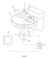
圖1係顯示研磨裝置之一種實施形態的模式圖。如圖1所示,研磨裝置具備:支撐研磨墊2之研磨台3;將具有膜之晶圓W(基板等)按壓於研磨墊2的研磨頭1;使研磨台3旋轉之台馬達6;用於在研磨墊2上供給漿液等之研磨液的研磨液供給噴嘴5;量測晶圓W之膜厚的膜厚檢測器40(本實施形態係光學式膜厚檢測器40);及用於控制研磨裝置之動作的動作控制部9。研磨墊2之上面構成研磨晶圓W的研磨面2a。
Hereinafter, embodiments of the present invention will be described in detail with reference to the drawings.
Fig. 1 is a schematic view showing an embodiment of a grinding device. As shown in FIG. 1 , the polishing device includes: a polishing table 3 supporting a
研磨頭1連結於頭軸桿10,頭軸桿10經由皮帶等連結機構而連結於無圖示之研磨頭馬達。研磨頭馬達使研磨頭1與頭軸桿10一起在箭頭指示之方向旋轉。研磨台3連接於台馬達6,台馬達6係以使研磨台3及研磨墊2在箭頭指示之方向旋轉的方式而構成。The grinding
晶圓W如下方式被研磨。使研磨台3及研磨頭1在圖1之箭頭指示的方向旋轉,而且從研磨液供給噴嘴5將研磨液供給至研磨台3上之研磨墊2的研磨面2a。晶圓W藉由研磨頭1以頭軸桿10為中心而旋轉,並在研磨墊2上存在研磨液狀態下,晶圓W藉由研磨頭1按壓於研磨墊2之研磨面2a。研磨台3將其中心CP作為中心而旋轉。晶圓W之表面藉由研磨液之化學性作用、與研磨液所含之研磨粒或是研磨墊2的機械性作用而被研磨。Wafer W was ground as follows. The polishing table 3 and the polishing
動作控制部9至少由1台電腦構成。動作控制部9具備:儲存有程式之記憶裝置9a;與按照程式中所含之命令執行運算的運算裝置9b。運算裝置9b包含按照儲存於記憶裝置9a之程式中所含的命令進行運算的CPU(中央處理裝置)或是GPU(圖形處理單元)等。記憶裝置9a具備:運算裝置9b可存取之主記憶裝置(例如隨機存取記憶體);與儲存資料及程式之輔助記憶裝置(例如,硬碟機或固態硬碟)。The
動作控制部9電性連接於膜厚檢測器40。本實施形態之膜厚檢測器40係將光引導至晶圓W表面,檢測來自晶圓W之反射光,並將依晶圓W之膜厚的信號輸出至動作控制部9。動作控制部9依據從膜厚檢測器40送來之信號(更具體而言,係來自晶圓W之反射光的強度量測資料)量測晶圓W之膜厚。The
本實施形態之膜厚檢測器40係光學式的膜厚檢測器,不過,只要可藉由動作控制部9量測晶圓W之膜厚,亦可係其他膜厚檢測器。換言之,膜厚檢測器40係檢測關於晶圓W之膜厚的物理量之檢測器。膜厚檢測器40之一例亦可係渦電流檢測器。渦電流檢測器係藉由其檢測器線圈使磁通通過晶圓W的導電性膜內而產生渦電流,檢測依晶圓W之膜厚的渦電流,並輸出渦電流信號。動作控制部9依據該渦電流信號量測晶圓W之膜厚。The
本實施形態之膜厚檢測器40係具備:發出光之光源44;分光器47;及連結於光源44及分光器47之光學檢測器頭7。光學檢測器頭7、光源44、及分光器47安裝於研磨台3,並與研磨台3及研磨墊2一體地旋轉。光學檢測器頭7之位置係研磨台3及研磨墊2每旋轉一圈時穿過研磨墊2上之晶圓W表面的位置。The
記憶裝置9a在其內部儲存有用於執行生成後述之光譜及檢測晶圓W的膜厚之程式。從光源44發出之光傳送至光學檢測器頭7,並從光學檢測器頭7引導至晶圓W表面。光在晶圓W表面反射,來自晶圓W表面之反射光藉由光學檢測器頭7接收,並送至分光器47。分光器47按照波長分解反射光。如此,膜厚檢測器40檢測各波長之反射光強度,並將反射光之強度量測資料送至動作控制部9。The memory device 9 a stores therein a program for executing the generation of a spectrum to be described later and the detection of the film thickness of the wafer W. The light emitted from the
圖2係研磨頭之剖面圖。如圖2所示,研磨頭1具備:用於對研磨墊2之研磨面2a按壓晶圓W之彈性膜65;保持彈性膜65之頭本體21;配置於頭本體21下方之環狀的驅動環62;及固定於驅動環62下面之環狀的扣環60。Figure 2 is a cross-sectional view of the grinding head. As shown in Figure 2, the polishing
彈性膜65安裝於頭本體21之下部。頭本體21固定於頭軸桿10之端部,頭本體21、彈性膜65、驅動環62、及扣環60係以藉由頭軸桿10之旋轉而一體地旋轉的方式構成。扣環60及驅動環62係構成可對頭本體21相對地上下移動。頭本體21藉由工程塑膠(例如,PEEK)等之樹脂而形成。The
彈性膜65之下面構成對研磨墊2之研磨面2a按壓晶圓W的基板按壓面65a。扣環60以包圍基板按壓面65a之方式配置,晶圓W藉由扣環60包圍。在彈性膜65與頭本體21之間設有4個壓力室70、71、72、73。The lower surface of the
壓力室70係位於中央之圓形狀的中央壓力室,壓力室73係位於最外周之環狀的邊緣壓力室,壓力室71、72分別係位於壓力室70與壓力室73之間的中間壓力室。The
壓力室70、71、72、73藉由彈性膜65與頭本體21而形成。中央之壓力室70係圓形,其他之壓力室71、72、73係環狀。此等壓力室70、71、72、73同心圓狀地排列(分割)。本實施形態係彈性膜65形成4個壓力室70~73,不過上述之壓力室的數量係例示,亦可適切變更。The
壓力室70、71、72、73中分別連接有氣體輸送管線F1、F2、F3、F4。氣體輸送管線F1、F2、F3、F4之一端連接在設於設置有研磨裝置之工廠作為公用設施的壓縮氣體供給源(無圖示)。壓縮空氣等之壓縮氣體通過氣體輸送管線F1、F2、F3、F4可分別供給至壓力室70、71、72、73。藉由在壓力室70~73中供給壓縮氣體,彈性膜65膨脹,壓力室70~73中之壓縮氣體經由彈性膜65將晶圓W按壓於研磨墊2的研磨面2a。壓力室70~73發揮用於將晶圓W按壓於研磨墊2之研磨面2a的致動器之功能。The
扣環60配置於彈性膜65之周圍,且係與研磨墊2之研磨面2a接觸的環狀構件。扣環60係以包圍晶圓W之最外周(周緣部)的方式而配置,防止在晶圓W研磨中,晶圓從研磨頭1彈出,並且調整研磨墊2之彈性動作(回彈(Rebound)),可調整晶圓W最外周之膜厚分布。The retaining
驅動環62之上部連接於環狀的扣環按壓裝置80。扣環按壓裝置80經由驅動環62對扣環60之整個上面60b賦予向下的負重,藉此,將扣環60之下面60a按壓於研磨墊2的研磨面2a。The top of the
扣環按壓裝置80具備:固定於驅動環62上部之環狀的活塞81;及連接於活塞81之上面的環狀之滾動隔膜82。在滾動隔膜82內部形成有扣環壓力室83。該扣環壓力室83經由氣體輸送管線F5而連結於上述壓縮氣體供給源。壓縮氣體通過氣體輸送管線F5而供給至扣環壓力室83中。The buckle
從上述壓縮氣體供給源供給壓縮氣體至扣環壓力室83時,滾動隔膜82將活塞81壓入下方,活塞81壓入驅動環62,進一步驅動環62將整個扣環60壓入下方。如此,扣環按壓裝置80將扣環60之下面60a按壓於研磨墊2的研磨面2a。驅動環62可裝卸地連結於扣環按壓裝置80。一種實施形態係扣環按壓裝置80亦可具有藉由使研磨頭1之下降力作用於扣環60,而將扣環60之下面60a按壓於研磨墊2的研磨面2a之構造。When compressed gas is supplied from the above-mentioned compressed gas supply source to the
氣體輸送管線F1、F2、F3、F4、F5經由安裝於頭軸桿10之旋轉接頭25而延伸。研磨裝置進一步具備壓力調整器R1、R2、R3、R4、R5,壓力調整器R1、R2、R3、R4、R5分別設於氣體輸送管線F1、F2、F3、F4、F5。來自壓縮氣體供給源之壓縮氣體通過壓力調整器R1~R5而分別獨立地供給至壓力室70~73、及扣環壓力室83內。壓力調整器R1~R5係以調節壓力室70~73及扣環壓力室83內之壓縮氣體壓力的方式而構成。壓力調整器R1~R5連接於動作控制部9。The gas delivery lines F1 , F2 , F3 , F4 , F5 extend through the rotary joint 25 installed on the
壓力調整器R1~R5可使壓力室70~73及扣環壓力室83之內部壓力彼此獨立變化,藉此,可獨立地調整在晶圓W對應之4個區域,亦即,中央部、內側中間部、外側中間部、及邊緣部之晶圓W對研磨面2a的按壓力、及扣環60對研磨墊2的按壓力。氣體輸送管線F1、F2、F3、F4、F5亦分別連接有大氣開放閥(無圖示),亦可將壓力室70~73及扣環壓力室83開放於大氣。本實施形態係彈性膜65形成4個壓力室70~73,不過,一種實施形態係彈性膜65亦可形成比4個少、或比4個多之壓力室。The pressure regulators R1-R5 can change the internal pressures of the pressure chambers 70-73 and the
圖3係顯示藉由動作控制部所生成之光譜的一例圖。圖3中,橫軸表示從晶圓反射之光的波長,縱軸表示從反射之光的強度導出的相對反射率。所謂相對反射率,係表示反射光之強度的指標值,且係光強度與指定的基準強度之比。在各波長中,藉由將光之強度(實測強度)除以指定的基準強度,可從實測強度除去裝置之光學系統及光源固有的強度變異等不需要之雜訊。Fig. 3 is a graph showing an example of a spectrum generated by a motion control unit. In FIG. 3 , the horizontal axis represents the wavelength of light reflected from the wafer, and the vertical axis represents the relative reflectance derived from the intensity of the reflected light. The relative reflectance is an index value representing the intensity of reflected light, and is the ratio of light intensity to a specified reference intensity. In each wavelength, by dividing the intensity of light (actually measured intensity) by the specified reference intensity, unnecessary noise such as intensity variation inherent in the optical system of the device and the light source can be removed from the measured intensity.
基準強度係就各波長預先量測的光強度,相對反射率係在各波長中算出。具體而言,藉由將各波長之光強度(實測強度)除以對應的基準強度而求出相對反射率。The reference intensity is the light intensity measured in advance for each wavelength, and the relative reflectance is calculated for each wavelength. Specifically, the relative reflectance was obtained by dividing the light intensity (measured intensity) of each wavelength by the corresponding reference intensity.
動作控制部9係以從反射光之強度量測資料生成反射光的光譜之方式而構成。反射光之光譜作為顯示反射光之波長與強度的關係之曲線(亦即分光波形)來表示。反射光之強度亦可作為反射率或相對反射率等之相對值來表示。The
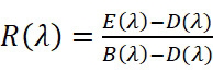
實際研磨時,係從實測強度減去黑位準(在遮蔽光之條件下獲得的背景強度)而求出修正實測強度,進一步從基準強度減去上述黑位準而求出修正基準強度,而後,藉由將修正實測強度除以修正基準強度而求出相對反射率。具體而言,相對反射率R(λ)可使用下列公式(1)求出。
[數學式1]
動作控制部9從反射光之強度量測資料生成如圖3所示的光譜。進一步,動作控制部9從反射光之光譜決定晶圓W的膜厚。反射光之光譜隨晶圓W的膜厚而變化。因此,動作控制部9可從反射光之光譜決定晶圓W的膜厚。以下,本說明書中,係將從來自研磨之晶圓W的反射光所生成之光譜稱為量測光譜。The
動作控制部9係以從量測光譜(亦即,量測資料)與複數個參考光譜(亦即,參考資料)之比較來決定膜厚的方式而構成。動作控制部9藉由比較在研磨中所生成之量測光譜與複數個參考光譜,決定形狀最接近量測光譜之參考光譜,而取得與該決定之參考光譜相關連的膜厚。形狀最接近量測光譜之參考光譜係參考光譜與量測光譜之間的相對反射率之差為最小的光譜。The
複數個參考光譜係藉由研磨與研磨對象之晶圓(以下,在本說明書中,晶圓W相當於研磨對象之晶圓)相同,或是具有同等初期膜厚之參考晶圓而預先取得者。研磨對象之晶圓係與參考晶圓不同的晶圓,且係執行膜厚之平坦化工序的晶圓。參考晶圓係執行將參考光譜與對應之膜厚相關連的工序之晶圓。A plurality of reference spectra are pre-acquired by polishing the same wafer as the wafer to be polished (hereinafter, in this specification, wafer W corresponds to the wafer to be polished), or a reference wafer having the same initial film thickness . The wafer to be polished is a wafer different from the reference wafer, and is a wafer on which a film thickness flattening process is performed. The reference wafer is the wafer on which the process of correlating the reference spectrum to the corresponding film thickness is performed.
各參考光譜可與取得其參考光譜時之膜厚相關連。亦即,各參考光譜係在不同膜厚時取得者,且複數個參考光譜對應於複數個不同的膜厚。因此,藉由決定形狀最接近量測光譜之參考光譜,即可估計現在的膜厚。Each reference spectrum can be associated with the film thickness at which the reference spectrum was obtained. That is, each reference spectrum is obtained at different film thicknesses, and multiple reference spectra correspond to multiple different film thicknesses. Therefore, by determining the reference spectrum whose shape is closest to the measured spectrum, the current film thickness can be estimated.
圖4係顯示取得複數個參考光譜之工序的一例圖。首先,準備與晶圓W相同或是具有同等膜厚之參考晶圓。參考晶圓被搬送至膜厚量測器170(參考圖1),參考晶圓之初期膜厚藉由膜厚量測器170而量測(參考步驟S101)。膜厚量測器170電性連接於動作控制部9。Fig. 4 is a diagram showing an example of the process of obtaining a plurality of reference spectra. First, a reference wafer that is the same as the wafer W or has the same film thickness is prepared. The reference wafer is transported to the film thickness measuring device 170 (refer to FIG. 1 ), and the initial film thickness of the reference wafer is measured by the film thickness measuring device 170 (refer to step S101 ). The film
其次,將作為研磨液之漿液供給至研磨頭1,而且研磨參考晶圓(參考步驟S102)。參考晶圓研磨中,在參考晶圓之表面照射光,而取得來自參考晶圓之反射光的光譜(亦即參考光譜)(參考步驟S103)。Next, a slurry as a polishing liquid is supplied to the polishing
參考光譜於研磨台3每旋轉一圈時取得。因此,在參考晶圓研磨中取得複數個參考光譜。參考晶圓之研磨結束後,參考晶圓再度被搬送至膜厚量測器170,來量測研磨後之參考晶圓的膜厚(亦即最後膜厚)(參考步驟S104)。The reference spectrum is obtained every time the grinding table 3 rotates once. Therefore, a plurality of reference spectra are obtained during reference wafer grinding. After the reference wafer is polished, the reference wafer is again transported to the film
參考晶圓之研磨率一定時,膜厚與研磨時間一起直線性減少。研磨率可藉由初期膜厚與最後膜厚之差除以到達最後膜厚的研磨時間而算出。參考光譜如上述,由於係研磨台3每旋轉一圈時週期性取得,因此,在取得各個參考光譜時之研磨時間可從研磨台3的旋轉速度算出。如此,動作控制部9決定對應於各參考光譜之膜厚(參考步驟S105)。When the polishing rate of the reference wafer is constant, the film thickness decreases linearly with the polishing time. The polishing rate can be calculated by dividing the difference between the initial film thickness and the final film thickness by the polishing time to reach the final film thickness. As mentioned above, the reference spectrum is obtained periodically when the grinding table 3 rotates once. Therefore, the grinding time when each reference spectrum is obtained can be calculated from the rotation speed of the grinding table 3 . In this way, the
各參考光譜可與對應之膜厚相關連(可相結合)。因此,動作控制部9藉由在晶圓W研磨中決定形狀最接近量測光譜之參考光譜,即可從與其參考光譜相關連之膜厚決定晶圓W現在的膜厚。Each reference spectrum can be associated (can be combined) with the corresponding film thickness. Therefore, the
以下,說明研磨研磨對象之晶圓W的工序。首先,需要決定研磨對象之晶圓W的膜厚均勻性保持在指定之容許範圍內的第一研磨條件(換言之,即最後目標膜厚平坦條件)。Hereinafter, the process of polishing the wafer W to be polished will be described. First, it is necessary to determine the first polishing condition (in other words, the final target flat film thickness condition) for maintaining the film thickness uniformity of the wafer W to be polished within a specified allowable range.
第一研磨條件亦可係以最後目標膜厚形成平坦之方式而預先決定的研磨條件(控制複數個壓力室70、71、72、73、83之各個壓力)。動作控制部9係以依據第一研磨條件控制複數個壓力室70、71、72、73、83之各個壓力,並研磨晶圓W之方式而構成。The first polishing condition may be a predetermined polishing condition (controlling the respective pressures of the plurality of
圖5係顯示依複數個壓力室所分割之晶圓的複數個按壓區域之圖。如圖5所示,動作控制部9依複數個壓力室70、71、72、73而分割成晶圓W上之複數個按壓區域A1~A4。此等按壓區域A1~A4與晶圓W之中心CPW同心圓狀地配置。在晶圓W之外緣形成有凹槽Nt。FIG. 5 is a diagram showing a plurality of pressing regions of a wafer divided according to a plurality of pressure chambers. As shown in FIG. 5 , the
一種實施形態係第一研磨條件亦可係依據在晶圓W研磨中藉由膜厚檢測器40所量測之膜厚,以晶圓W之各區域A1~A4的膜厚(平均膜厚)變成整個晶圓W之平均膜厚的方式,實時反饋控制各壓力室70~73之壓力的研磨條件(CLC:閉環控制)。更具體而言,動作控制部9依據從膜厚檢測器40輸出之信號所量測的晶圓W之膜厚,算出在各個按壓區域A1~A4的平均膜厚值。然後,動作控制部9以減少按壓區域A1~A4之各個平均膜厚值與整個晶圓W的平均膜厚值之差分的方式,藉由控制各個壓力調整器R1~R4來控制對應於按壓區域A1~A4之壓力室70~73內的壓力。One embodiment is that the first polishing condition can also be based on the film thickness measured by the
動作控制部9亦可依據與上述方法同樣之方法,藉由控制壓力調整器R5,來控制扣環壓力室83內之壓力。The
圖6係顯示以第一研磨條件研磨晶圓時之晶圓的研磨形貌圖。圖6中橫軸表示晶圓W之半徑方向的距離,縱軸表示晶圓W之膜厚分布。圖6中之粗線表示位於晶圓W最外周之對應於壓力室73的按壓區域A4、與按壓區域A4內側之按壓區域的邊界線。圖6所示之實施形態關於晶圓W之研磨形貌,係說明以指定時間研磨晶圓W時在研磨後之晶圓W的半徑方向之膜厚分布,不過,晶圓W之研磨形貌亦可包含在晶圓W半徑方向之研磨率分布。FIG. 6 is a graph showing the grinding topography of the wafer when the wafer is ground under the first grinding condition. In FIG. 6 , the horizontal axis represents the distance in the radial direction of the wafer W, and the vertical axis represents the film thickness distribution of the wafer W. The thick line in FIG. 6 indicates the boundary line between the pressing area A4 corresponding to the
以第一研磨條件研磨晶圓W時,包含晶圓W之中央部的其他區域(亦即,除了最外周之區域)係晶圓W之膜厚的均勻性保持在指定之容許範圍內,另外,包含晶圓W最外周之特定區域係晶圓W之殘留膜(研磨後之膜厚)在半徑方向的變異程度大。亦即,在包含晶圓W最外周之特定區域內,膜厚大之部分與小之部分的膜厚差變大。晶圓W之最外周因為研磨墊2之回彈的影響等,研磨形貌容易急遽地變成不對稱,僅調整包含晶圓W最外周之特定區域的壓力室之壓力,不易獲得平坦之膜厚分布。在包含晶圓W最外周之特定區域內的研磨後之膜厚的變異程度(即所謂殘留膜範圍),在第一研磨條件下有研磨時間愈長而變異程度愈大的趨勢。When the wafer W is ground under the first grinding condition, the uniformity of the film thickness of the wafer W in other areas including the central part of the wafer W (that is, the area except the outermost periphery) is kept within the specified allowable range, and in addition , the specific region including the outermost periphery of the wafer W has a large variation in the radial direction of the residual film (film thickness after polishing) of the wafer W. That is, in a specific region including the outermost periphery of the wafer W, the difference in film thickness between a portion with a large film thickness and a portion with a small film thickness becomes large. The outermost periphery of the wafer W is likely to rapidly become asymmetrical due to the impact of the rebound of the
因此,本實施形態係動作控制部9以依據使在晶圓W最外周之晶圓W半徑方向的膜厚之變異程度減少的第二研磨條件來研磨晶圓W之方式而構成。以下所示之實施形態,作為晶圓W之特定區域的一例,係說明使在晶圓W之膜厚最外周的晶圓W之膜厚的變異程度減少之實施形態,不過,晶圓W之特定區域不限定於晶圓W的最外周。即使在除了晶圓W最外周之其他區域,仍有可能發生晶圓W之膜厚的變異。Therefore, in this embodiment, the
圖7係顯示第二研磨條件之圖。圖7中橫軸表示晶圓W之半徑方向的距離,縱軸表示晶圓W之膜厚分布。圖7所示之實施形態關於晶圓W的研磨形貌,係說明指定時間研磨晶圓W時,研磨後在晶圓W之半徑方向的膜厚分布,不過晶圓W之研磨形貌亦可包含在晶圓W之半徑方向的研磨率分布。Figure 7 is a graph showing the second milling conditions. In FIG. 7 , the horizontal axis represents the distance in the radial direction of the wafer W, and the vertical axis represents the film thickness distribution of the wafer W. The embodiment shown in FIG. 7 is about the grinding shape of wafer W, which is to explain the film thickness distribution in the radial direction of wafer W after grinding when wafer W is ground for a specified time, but the grinding shape of wafer W can also be The polishing rate distribution in the radial direction of the wafer W is included.
動作控制部9依據第一研磨條件研磨與研磨對象之晶圓W相同,或是具有同等初期膜厚之晶圓。然後,動作控制部9依據藉由以第一研磨條件研磨而獲得之第一研磨形貌(研磨後之晶圓W的膜厚分布或研磨率分布)來決定第二研磨條件。第二研磨條件係以形成具有與第一研磨形貌之分布(更具體而言,係對應於特定壓力室之晶圓W上的按壓區域分布)相反分布的第二研磨形貌之方式而預先決定(調整)的研磨條件。The
換言之,第二研磨條件係更積極地研磨在以第一研磨條件研磨之研磨後的晶圓W最外周之膜厚為厚的部分,而抑制在研磨後之晶圓W最外周的膜厚為薄之部分的研磨之研磨條件。第二研磨形貌對第一研磨形貌之分布,具有表示晶圓W之膜厚厚度或研磨率之數值的正負符號顛倒之分布。顯示第二研磨形貌之分布的曲線與顯示第一研磨形貌之分布的曲線理想上係彼此線對稱。In other words, the second polishing condition is to more actively polish the portion where the film thickness of the outermost periphery of the polished wafer W polished under the first polishing condition is thicker, and suppress the film thickness of the outermost periphery of the polished wafer W from Grinding conditions for grinding thin parts. The distribution of the second polishing topography to the first polishing topography has a distribution in which the positive and negative signs of the values representing the film thickness of the wafer W or the polishing rate are reversed. The curve showing the distribution of the second abrasive topography and the curve showing the distribution of the first abrasive topography are ideally line-symmetric to each other.
圖7所示之實施形態係從晶圓W之半徑方向的距離、與對應於距離之晶圓W的膜厚,在特定座標系統上之膜厚分布中,顯示晶圓W最外周之膜厚分布的曲線(顯示第二研磨形貌之分布的曲線),將基準線作為中心,對顯示以第一研磨條件所研磨之晶圓W最外周的膜厚分布之曲線(參考圖7之一點鏈線)係線對稱。另外,圖7所示之實施形態係顯示第二研磨形貌之分布的曲線作為理想之曲線來描繪。The embodiment shown in FIG. 7 is the distance from the radial direction of the wafer W and the film thickness of the wafer W corresponding to the distance. In the film thickness distribution on a specific coordinate system, the film thickness of the outermost periphery of the wafer W is displayed. The curve of the distribution (the curve showing the distribution of the second grinding morphology), with the reference line as the center, is compared with the curve showing the film thickness distribution of the outermost periphery of the wafer W ground with the first grinding condition (refer to the dot chain in Figure 7 line) is line-symmetric. In addition, in the embodiment shown in FIG. 7 , the curve showing the distribution of the second polished morphology is drawn as an ideal curve.
第二研磨條件藉由研磨與研磨對象之晶圓W相同,或是具有同等初期膜厚之晶圓來決定。首先,預先以第一研磨條件研磨晶圓W,並確認第一研磨形貌。然後,進一步研磨另外的晶圓,以研磨結束後之研磨形貌具有與第一研磨形貌之分布相反分布之方式,實驗性地決定第二研磨條件。或是,一種實施形態首先以第一研磨條件研磨晶圓W,然後,繼續從第一研磨條件切換研磨條件來研磨晶圓W。並以研磨結束後之研磨形貌具有平坦的分布之方式,來實驗性決定來自第一研磨條件之切換條件的第二研磨條件。一種實施形態係第二研磨條件亦可從由預先儲存於記憶裝置9a中之研磨條件與研磨形貌構成的資料庫選擇最佳者,及/或是藉由研磨模擬來決定。The second polishing condition is determined by polishing the same wafer W as the polishing object, or a wafer having the same initial film thickness. First, the wafer W is ground in advance under the first grinding condition, and the first grinding shape is confirmed. Then, another wafer was further polished, and the second polishing conditions were experimentally determined so that the polished morphology after polishing had a distribution opposite to that of the first polished morphology. Alternatively, in one embodiment, the wafer W is ground first under the first grinding condition, and then the wafer W is ground continuously by switching the grinding condition from the first grinding condition. In addition, the second grinding condition from the switching condition of the first grinding condition was experimentally determined in such a way that the grinding morphology after grinding had a flat distribution. One embodiment is that the second grinding condition can also be selected from a database consisting of grinding conditions and grinding shapes pre-stored in the memory device 9a, and/or determined by grinding simulation.
動作控制部9係在其記憶裝置9a中儲存有第二研磨條件,並依據第二研磨條件研磨晶圓W之方式而構成。更具體而言,動作控制部9係以依據第二研磨條件在複數個壓力室70、71、72、73、83中預先決定特定壓力室之壓力的固定值進行控制,並研磨晶圓W。第二研磨條件包含以依據第二研磨形貌預先決定特定壓力室之壓力的固定值進行控制,並研磨晶圓W的研磨條件。The
本實施形態之特定壓力室包含:按壓晶圓W最外周之邊緣壓力室73;及鄰接於邊緣壓力室73之鄰接壓力室。鄰接壓力室包含中間壓力室72及扣環壓力室83之至少1個壓力室。本實施形態之鄰接壓力室係中間壓力室72及扣環壓力室83兩者。一種實施形態係特定壓力室亦可僅係邊緣壓力室73。The specific pressure chamber of this embodiment includes: an
第二研磨條件包含調整特定壓力室之壓力而決定的研磨條件。一種實施形態係第二研磨條件亦可包含調整特定壓力室以外之壓力室的壓力而決定之研磨條件。例如,特定壓力室係邊緣壓力室73時,第二研磨條件包含調整鄰接於邊緣壓力室73之鄰接壓力室的壓力而決定之研磨條件。The second grinding condition includes the grinding condition determined by adjusting the pressure of a specific pressure chamber. One embodiment is that the second polishing conditions may also include polishing conditions determined by adjusting the pressure of pressure chambers other than the specific pressure chamber. For example, when the specific pressure chamber is the
一種實施形態係第二研磨條件亦可包含調整以包圍晶圓W最外周之方式而配置的扣環60之對研磨面2a的按壓力而決定之研磨條件。此時,動作控制部9依據第二研磨條件控制使研磨頭1之下降力作用於扣環60的扣環按壓裝置80。In one embodiment, the second polishing conditions may also include polishing conditions determined by adjusting the pressing force of the retaining
本實施形態係動作控制部9依據第二研磨條件控制邊緣壓力室73及鄰接壓力室72、83之各個壓力,同時依據第一研磨條件反饋控制除去此等邊緣壓力室73及鄰接壓力室72、83之其他壓力室70、71的各個壓力。In this embodiment, the
第一研磨條件係在研磨中,依據從膜厚檢測器40所輸出之信號,以減少對應於各個其他壓力室70、71之區域的平均膜厚值與整個晶圓W之平均膜厚值的差分之方式,反饋控制壓力室70、71之各個壓力的研磨條件。The first polishing condition is to reduce the difference between the average film thickness value of the area corresponding to each
圖8係顯示以第一研磨條件及第二研磨條件所研磨之晶圓的研磨率之圖。圖8中,橫軸表示晶圓W之半徑方向的距離,縱軸表示晶圓W之研磨率。圖8放大顯示晶圓W之外側部分的研磨率。如圖8所示,第一研磨條件下在晶圓W上之按壓區域A4的研磨率與第二研磨條件下在晶圓W上之按壓區域A4的研磨率彼此顛倒。因此,動作控制部9藉由組合第一研磨條件及第二研磨條件來研磨晶圓W,可使晶圓W最外周之膜厚的均勻性提高。FIG. 8 is a graph showing the polishing rates of wafers polished under the first polishing condition and the second polishing condition. In FIG. 8 , the horizontal axis represents the distance in the radial direction of the wafer W, and the vertical axis represents the polishing rate of the wafer W. FIG. 8 shows an enlarged view of the polishing rate of the outer portion of the wafer W. As shown in FIG. As shown in FIG. 8 , the polishing rate of the pressing region A4 on the wafer W under the first polishing condition and the polishing rate of the pressing region A4 on the wafer W under the second polishing condition are reversed. Therefore, the
圖9係顯示研磨研磨對象之晶圓的工序之一例圖。如圖9之步驟S201所示,動作控制部9以第一研磨條件研磨晶圓W(第一研磨工序)。然後,動作控制部9判斷是否滿足指定之切換條件(參考步驟S202),未滿足切換條件時(參考步驟S202之「否(No)」),繼續進行步驟S201。滿足切換條件時(參考步驟S202之「是(Yes)」),動作控制部9將研磨條件從第一研磨條件切換成第二研磨條件(參考步驟S203),並以第二研磨條件研磨晶圓W(第二研磨工序)。FIG. 9 is a diagram showing an example of a process of polishing a wafer to be polished. As shown in step S201 of FIG. 9 , the
在晶圓W最外周(亦即,特定區域)之殘留膜厚的變異程度(更具體而言,係膜厚的最大值與最小值之差)相當大狀態下,即使將研磨條件從第一研磨條件切換成第二研磨條件,可能仍無法消除晶圓W最外周之膜厚的變異。因此,動作控制部9關於上述切換條件,亦可在第一研磨條件下,於晶圓W研磨中,晶圓W最外周之膜厚的最大值與最小值之差(即所謂殘留膜範圍)大幅超過指定的臨限值時,將研磨條件從第一研磨條件切換成第二研磨條件(第一切換條件)。In the state where the degree of variation of the residual film thickness (more specifically, the difference between the maximum value and the minimum value of the film thickness) at the outermost periphery of the wafer W (that is, a specific region) is quite large, even if the polishing conditions are changed from the first Switching the polishing condition to the second polishing condition may not eliminate the variation of the film thickness at the outermost periphery of the wafer W. Therefore, the
對應於特定壓力室之晶圓W在特定區域內的膜厚變異程度大時,即使調整特定壓力室之壓力,可能仍無法消除膜厚的變異。因此,上述實施形態係動作控制部9在第一研磨條件下之晶圓W的殘留膜範圍大幅超過指定之臨限值時,將研磨條件從第一研磨條件切換成第二研磨條件。When the film thickness variation of the wafer W corresponding to a specific pressure chamber is large in a specific region, even if the pressure of the specific pressure chamber is adjusted, the variation of the film thickness may not be eliminated. Therefore, in the above embodiment, the
剩餘之研磨時間相當短狀態下,即使將研磨條件從第一研磨條件切換成第二研磨條件,可能仍無法消除晶圓W之特定區域的膜厚變異。因此,動作控制部9關於上述切換條件,亦可依據為了藉由以第二研磨條件研磨來消除晶圓W最外周之膜厚的最大值與最小值之差的需要時間、與到達最後目標膜厚的剩餘研磨時間,而將研磨條件從第一研磨條件切換成第二研磨條件(第二切換條件)。When the remaining polishing time is relatively short, even if the polishing condition is switched from the first polishing condition to the second polishing condition, the film thickness variation in a specific region of the wafer W may still not be eliminated. Therefore, the
藉由決定第二研磨條件之過程預先瞭解在第二研磨條件下研磨晶圓W時的研磨率。因此,動作控制部9在第二研磨條件下研磨晶圓W時,可算出為了減少(消除)在第一研磨條件下於晶圓W研磨中晶圓W之殘留膜範圍的需要時間。因此,一種實施形態係動作控制部9亦可在第二研磨條件下需要研磨時間到達或是接近指定的剩餘時間時,將研磨條件從第一研磨條件切換成第二研磨條件。指定之剩餘時間,例如與切換時機以後,在第二研磨條件下研磨晶圓W時,晶圓W之膜厚變成最後目標膜厚的需要時間相同。The polishing rate when the wafer W is polished under the second polishing condition is known in advance through the process of determining the second polishing condition. Therefore, when the wafer W is polished under the second polishing condition, the
更具體而言,動作控制部9算出在第一研磨條件下研磨晶圓W中,為了以第二研磨條件減少晶圓W之殘留膜範圍而需要的時間(亦即,上述需要研磨時間)、與剩餘的研磨時間(亦即,上述剩餘時間)。剩餘之研磨時間依據下列計算公式算出。剩餘研磨時間=(晶圓W之現在膜厚-晶圓W之目標膜厚)/第二研磨條件之假設研磨率More specifically, the
需要研磨時間比剩餘時間小時(需要研磨時間<<剩餘時間),以第二研磨條件之研磨時間變長,導致晶圓W之殘留膜形貌惡化。需要研磨時間與剩餘時間相同時(需要研磨時間=剩餘時間),消除晶圓W之殘留膜範圍,晶圓W之膜厚到達目標膜厚(理想狀態)。需要研磨時間比剩餘時間大時(需要研磨時間>剩餘時間),在消除殘留膜範圍之前,晶圓W之膜厚即變成目標膜厚,而無法消除殘留膜範圍。如此情況下繼續研磨時導致過度研磨。因此,動作控制部9於需要研磨時間與剩餘時間相同時,應將研磨條件從第一研磨條件切換成第二研磨條件。The required polishing time is shorter than the remaining time (required polishing time<<remaining time), and the polishing time under the second polishing condition becomes longer, resulting in deterioration of the remaining film morphology of the wafer W. When the required grinding time is the same as the remaining time (required grinding time = remaining time), the remaining film range of wafer W is eliminated, and the film thickness of wafer W reaches the target film thickness (ideal state). When the required grinding time is greater than the remaining time (required grinding time > remaining time), the film thickness of wafer W becomes the target film thickness before the remaining film range is eliminated, and the remaining film range cannot be eliminated. Continuing to grind in this condition results in overgrinding. Therefore, the
若採用第二切換條件,總研磨量有差異時,由於可變更可容許以第一研磨條件研磨的殘留膜範圍,因此,例如晶圓W之初期膜厚有差異時,可依其最佳化。另外,所謂「達到最後目標膜厚的需要時間」,是指除去晶圓W上之膜而研磨情況下,最後目標膜厚為零,亦即為了清除多餘膜的需要時間。If the second switching condition is adopted, when there is a difference in the total polishing amount, since the range of the residual film that can be polished with the first polishing condition can be changed, for example, when there is a difference in the initial film thickness of the wafer W, it can be optimized accordingly. . In addition, the "required time to reach the final target film thickness" refers to the time required to remove the excess film when the final target film thickness is zero when the film on the wafer W is removed and polished.
一種實施形態係動作控制部9亦可依據第一切換條件及第二切換條件,而將研磨條件從第一研磨條件切換成第二研磨條件。一種實施形態係動作控制部9亦可於整個晶圓W之平均膜厚變成指定膜厚時,將研磨條件從第一研磨條件切換成第二研磨條件。一種實施形態係動作控制部9亦可在晶圓W之研磨時間到達指定的研磨時間時,將研磨條件從第一研磨條件切換成第二研磨條件。One embodiment is that the
動作控制部9執行圖9之步驟S203後,藉由從膜厚檢測器40收到表示整個晶圓W之平均膜厚到達目標膜厚,或是形成於晶圓W上之材料到達與不同材料之界面的終點檢測信號(參考步驟S204之「是」),而結束晶圓W的研磨(參考步驟S205)。未收到終點檢測信號時(參考步驟S204之「否」),動作控制部9繼續以第二研磨條件研磨晶圓W。動作控制部9在收到終點檢測信號時,而在特定區域內殘留膜範圍並非在指定值以下時,亦可繼續以第二研磨條件研磨晶圓W。此外,動作控制部9在收到終點檢測信號時,而在特定區域內之殘留膜範圍並非在指定值以下時,亦可發出警報。After the
上述實施形態中,研磨頭1具有複數個壓力室(氣囊),不過,用於按壓晶圓W之按壓元件不限於此。在晶圓W之半徑方向排列有複數個對晶圓W賦予相同壓力之按壓元件時,可適用本發明之技術性思想。按壓元件例如有壓電元件。In the above embodiment, the polishing
圖10係顯示將參考光譜與對應之膜厚相關連的工序之一例圖。首先,準備與晶圓W相同,或是具有同等膜厚之參考晶圓。參考晶圓被搬送至膜厚量測器170(參考圖1),藉由膜厚量測器170量測參考晶圓之初期膜厚(參考步驟S301)。膜厚量測器170電性連接於動作控制部9。動作控制部9依據藉由膜厚量測器170所量測之參考晶圓的膜厚(分布),決定用於取得在廣泛膜厚範圍中之參考光譜的參考位置(參考步驟S302)。Fig. 10 is a diagram showing an example of a process of correlating reference spectra with corresponding film thicknesses. First, a reference wafer that is the same as the wafer W or has the same film thickness is prepared. The reference wafer is transported to the film thickness measuring device 170 (refer to FIG. 1 ), and the initial film thickness of the reference wafer is measured by the film thickness measuring device 170 (refer to step S301 ). The film
如此,動作控制部9從膜厚量測器170取得關於參考晶圓之圓周上的一部分之特定位置的資訊。膜厚量測器170亦可配置於研磨裝置內部。此時,膜厚量測器170構成研磨裝置之構成元件的一部分。一種實施形態係膜厚量測器170亦可配置於研磨裝置的外部。In this way, the
參考晶圓為了獲得對應於各種膜厚之參考光譜而被研磨。動作控制部9依據量測之參考晶圓的膜厚,決定獲得最大膜厚值之最大膜厚位置(亦即,參考晶圓之膜厚為厚的部位)、與獲得最小膜厚值之最小膜厚位置(亦即,參考晶圓之膜厚為薄的部位),並將最大膜厚位置及最小膜厚位置中之其中一個決定為參考位置。一種實施形態係動作控制部9亦可將最大膜厚位置及最小膜厚位置兩者決定為參考位置。A reference wafer is ground to obtain reference spectra corresponding to various film thicknesses. The
一種實施形態係動作控制部9亦可依據量測之參考晶圓的膜厚,決定最大膜厚值、與最小膜厚值,並算出整個參考晶圓之平均膜厚值與最大膜厚值的差分、及整個參考晶圓之平均膜厚值與最小膜厚值的差分,並將獲得差分最大之膜厚值的參考晶圓上之位置決定為參考位置。One embodiment is that the
其次,將作為研磨液之漿液供給至研磨頭1並且研磨參考晶圓(參考步驟S303)。參考晶圓研磨中,在參考晶圓表面照射光,而取得來自參考晶圓之反射光的光譜(亦即參考光譜)(參考步驟S304)。Next, the slurry as a polishing liquid is supplied to the polishing
動作控制部9於研磨台3每旋轉一圈取得在參考晶圓上之各量測點的參考光譜。動作控制部9於研磨中,以膜厚檢測器40穿過參考晶圓上之參考位置的方式,控制研磨頭1之旋轉速度及研磨台3的旋轉速度之至少一方。藉由如此控制,膜厚檢測器40檢測參考位置之反射光,動作控制部9取得包含參考位置之參考光譜。The
動作控制部9藉由取得包含參考位置之參考光譜,可取得膜厚值之廣泛範圍中的參考光譜。因此,動作控制部9可更確實地決定形狀最接近研磨中所生成之量測光譜的參考光譜,結果可量測(取得)具有所有膜厚之晶圓W的膜厚。The
研磨台3每旋轉一圈即取得參考光譜。因此,在研磨參考晶圓中取得複數個參考光譜。參考晶圓之研磨結束後,將參考晶圓再度搬送至膜厚量測器170,量測研磨後之參考晶圓的膜厚(亦即最後膜厚)(參考步驟S305)。The reference spectrum is obtained every time the grinding table 3 rotates once. Therefore, a plurality of reference spectra are taken on a ground reference wafer. After the grinding of the reference wafer is finished, the reference wafer is transported to the film
參考晶圓之研磨率一定時,膜厚與研磨時間一起直線性減少。研磨率可藉由將初期膜厚與最後膜厚之差除以到達最後膜厚的研磨時間而算出。參考光譜如上述,由於係研磨台3每旋轉一圈時週期性取得,因此,可從研磨台3之旋轉速度算出取得各個參考光譜時的研磨時間。如此,動作控制部9決定對應於各參考光譜之膜厚(參考步驟S306)。When the polishing rate of the reference wafer is constant, the film thickness decreases linearly with the polishing time. The polishing rate can be calculated by dividing the difference between the initial film thickness and the final film thickness by the polishing time to reach the final film thickness. As mentioned above, the reference spectrum is obtained periodically when the polishing table 3 rotates once, so the polishing time for obtaining each reference spectrum can be calculated from the rotation speed of the polishing table 3 . In this way, the
各參考光譜可與對應之膜厚相關連(可相結合)。因此,動作控制部9藉由在晶圓W研磨中決定形狀最接近量測光譜之參考光譜,即可從與其參考光譜相關連之膜厚決定晶圓W現在的膜厚。Each reference spectrum can be associated (can be combined) with the corresponding film thickness. Therefore, the
圖11係顯示研磨研磨對象之晶圓的工序之一例圖。為了提高研磨對象之晶圓W的膜厚均勻性,需要決定晶圓W圓周上之一部分的特定位置。因此,如圖11之步驟S401所示,晶圓W被搬送至膜厚量測器170,並藉由膜厚量測器170量測晶圓W之初期膜厚。FIG. 11 is a diagram showing an example of a process of polishing a wafer to be polished. In order to improve the film thickness uniformity of the wafer W to be polished, it is necessary to determine a specific position of a part of the circumference of the wafer W. Therefore, as shown in step S401 of FIG. 11 , the wafer W is transported to the film
然後,與圖10之步驟S302同樣地,動作控制部9依據藉由膜厚量測器170所量測之晶圓W的膜厚,來決定晶圓W之特定位置(參考步驟S402)。Then, similarly to step S302 in FIG. 10 , the
特定位置之決定方法與參考位置的決定方法同樣。動作控制部9依據研磨前所量測之晶圓W的膜厚,決定獲得最大膜厚值之最大膜厚位置(亦即,晶圓W之膜厚為厚的部位)、與獲得最小膜厚值之最小膜厚位置(亦即,晶圓W之膜厚為薄的部位),並將最大膜厚位置及最小膜厚位置中之至少1個決定為特定位置。The determination method of the specific position is the same as that of the reference position. The
一種實施形態係動作控制部9亦可依據研磨前所量測之晶圓W的膜厚來決定最大膜厚值、與最小膜厚值,並算出整個晶圓W之平均膜厚值與最大膜厚值的差分、及整個晶圓W之平均膜厚值與最小膜厚值的差分,而將獲得差分最大之膜厚值的晶圓W上之位置決定為特定位置。One embodiment is that the
動作控制部9取得藉由膜厚量測器170所量測之晶圓W的膜厚分布資訊,來決定晶圓W之特定位置。一種實施形態為將膜厚量測器170配置於研磨裝置外部時,動作控制部9亦可從晶圓W之膜厚分布僅取得所指定之特定位置的位置資訊。The
動作控制部9決定了晶圓W之特定位置後,開始研磨晶圓W(參考步驟S403)。該研磨中,在晶圓W表面照射光,動作控制部9取得來自晶圓W之反射光的光譜(亦即,量測光譜)。動作控制部9決定形狀最接近所取得之量測光譜的參考光譜,而取得與決定之參考光譜相關連的膜厚(參考步驟S404)。After determining the specific position of the wafer W, the
動作控制部9藉由控制壓力調整器R1、R2、R3、R4,而依據晶圓W之膜厚來調整晶圓W對研磨面2a的按壓力。本實施形態係動作控制部9將晶圓W上之區域依複數個壓力室70、71、72、73而區分成複數個按壓區域A1、A2、A3、A4(參考圖12)。The
圖12係顯示晶圓被區分成複數個按壓區域之圖。圖12係將晶圓W上之區域區分成對應於壓力室70之按壓區域A1;對應於壓力室71之按壓區域A2;對應於壓力室72之按壓區域A3、及對應於壓力室73之按壓區域A4。按壓區域A1具有圓形狀,按壓區域A2~A4分別具有環狀形狀。此等按壓區域A1~A4與晶圓W之中心CPW同心狀地配置。動作控制部9係以複數個按壓區域分別獨立地調整晶圓W之按壓力的方式而構成。FIG. 12 is a diagram showing that a wafer is divided into a plurality of pressing regions. FIG. 12 divides the area on the wafer W into the pressing area A1 corresponding to the
如圖12所示,在晶圓W之按壓區域A4中存在特定位置IP。圖12所示之實施形態,特定位置IP係晶圓W上的一點,不過,在晶圓W上之狹窄區域也存在複數個點時,特定位置IP亦為晶圓W上寬廣區域中存在的複數個點。因此,動作控制部9決定包含特定位置IP之控制對象區域CA。此外,將包含特定位置IP之某種程度大小的區域作為控制對象區域時,可穩定地進行以下說明之膜厚均勻性的調整。本實施形態之控制對象區域CA係在周方向範圍(亦即,屬於區域A1~A4之其中一個的範圍)內決定。一種實施形態於特定位置IP係晶圓W上之一點時,控制對象區域CA亦可係晶圓W上的一點。As shown in FIG. 12 , there is a specific position IP in the pressing area A4 of the wafer W. In the embodiment shown in FIG. 12, the specific position IP is a point on the wafer W. However, when there are multiple points in a narrow area on the wafer W, the specific position IP also exists in a wide area on the wafer W. Plural dots. Therefore, the
動作控制部9決定控制對象區域CA中之控制對象膜厚值,且依據藉由膜厚檢測器40所量測之晶圓W的膜厚算出整個晶圓W之平均膜厚值。控制對象膜厚值亦可相當於依據藉由膜厚檢測器40所量測之晶圓W的膜厚所決定之最大膜厚值或最小膜厚值,亦可係最大膜厚值及最小膜厚值兩者。一種實施形態係控制對象膜厚值亦可係控制對象區域CA中之複數個膜厚值的平均值。The
動作控制部9係以膜厚檢測器40穿過晶圓W上之控制對象區域CA的方式,來控制研磨頭1之旋轉速度及研磨台3的旋轉速度之至少一方。為了進行該控制,動作控制部9在晶圓W研磨中需要決定控制對象區域CA之位置。The
決定控制對象區域CA之位置的方法之一例為動作控制部9在晶圓W研磨中,特定晶圓W周方向之角度(亦即,晶圓角度)的基準位置(例如,圖12之凹槽位置Nt),並決定控制對象區域CA之位置作為晶圓角度。One example of a method of determining the position of the control target area CA is that the
假定晶圓W對研磨頭1在圓周方向無偏差時,在開始研磨時刻晶圓W對研磨頭1之安裝角度始終保持一定,藉由掌握研磨頭1藉由旋轉編碼器152(參照圖13)之旋轉角度,動作控制部9特定凹槽位置Nt,並決定控制對象區域CA之位置。即使不特定凹槽位置Nt之位置,因為預先決定了凹槽位置Nt與控制對象區域CA之位置關係,所以仍可從研磨頭1之旋轉角度決定控制對象區域CA的位置。Assuming that there is no deviation between the wafer W and the grinding
另外,晶圓W藉由作用於晶圓W與研磨頭1之間的摩擦力,可能對研磨頭1在圓周方向偏差。此時,因為凹槽位置Nt與研磨頭1之相對角度亦偏差,所以動作控制部9在晶圓W研磨中,實時特定晶圓W之凹槽位置Nt,並依據凹槽位置Nt決定控制對象區域CA的位置。In addition, the wafer W may deviate from the polishing
圖13係顯示凹槽檢測裝置之圖。如圖13所示,研磨裝置亦可具備檢測晶圓W之凹槽位置Nt的凹槽檢測裝置151。凹槽檢測裝置151亦可由渦電流檢測器、光學式檢測器、或影像檢測器等之檢測器構成。圖13所示之實施形態係將凹槽檢測裝置151配置於研磨台3的側方。研磨頭1移動至保持於研磨頭1之晶圓W的周緣部(更具體而言,係凹槽位置Nt)從研磨墊2擠出的位置,並使晶圓W旋轉。Fig. 13 is a diagram showing a groove detecting device. As shown in FIG. 13 , the polishing apparatus may include a
凹槽檢測裝置151檢測從研磨墊2擠出狀態下旋轉之晶圓W的凹槽位置Nt,並將檢測信號輸出至動作控制部9。旋轉編碼器152檢測依研磨頭1之旋轉角度的信號,並將檢測信號輸出至動作控制部9。如此,動作控制部9取得凹槽位置Nt與研磨頭1之旋轉角度的關係,可實時決定凹槽位置Nt與研磨頭1之相對角度。一種實施形態係動作控制部9亦可依據從膜厚檢測器40輸出之信號來特定凹槽位置Nt。此時,膜厚檢測器40相當於凹槽檢測裝置。The
圖14A及圖14B係顯示穿過晶圓表面上之膜厚檢測器的移動路徑圖。圖14A及圖14B係以5條虛線顯示膜厚檢測器40的移動路徑。圖14A及圖14B所示之實施形態係膜厚檢測器40在研磨台3旋轉第1圈時穿過特定位置IP。14A and 14B are diagrams showing the path of movement through a film thickness detector on the surface of a wafer. 14A and 14B show the moving path of the
如圖14A及圖14B所示,動作控制部9藉由控制研磨頭1之旋轉速度及研磨台3之旋轉速度的至少一方,可控制膜厚檢測器40之移動路徑。因此,動作控制部9係以膜厚檢測器40穿過晶圓W表面上之特定位置IP的方式,依據所決定之相對角度,控制研磨頭1之旋轉速度及研磨台3之旋轉速度的至少一方。As shown in FIGS. 14A and 14B , the
例如,動作控制部9藉由決定研磨頭1之旋轉速度與研磨台3的旋轉速度之間的旋轉速度比,可決定膜厚檢測器40之移動路徑。圖14A所示之實施形態中的旋轉速度比、與圖14B所示之實施形態中的旋轉速度比彼此不同。因此,變更凹槽位置Nt與研磨頭1之相對角度時,動作控制部9係以膜厚檢測器40穿過晶圓W表面上之特定位置IP的方式,決定研磨頭1之旋轉速度與研磨台3的旋轉速度之間的旋轉速度比。For example, the
如此,動作控制部9依據從膜厚檢測器40輸出之信號,量測在研磨中包含特定位置IP之控制對象區域CA的膜厚,並藉由依據量測之膜厚控制壓力調整器R1~R4,來控制對應於控制對象區域CA之研磨頭1的壓力室70~73中之壓力。In this way, the
更具體而言,如圖11之步驟S405所示,動作控制部9係以減少控制對象膜厚值與整個晶圓W之平均膜厚值的差分之方式,控制對應於特定位置IP(或是控制對象區域CA)之研磨頭1的壓力室70~73中之壓力。圖12所示之實施形態係控制對象區域CA存在於晶圓W之對應於按壓區域A4的位置,區域A4對應於壓力室73。因此,動作控制部9控制壓力調整器R4來控制壓力室73中的壓力。More specifically, as shown in step S405 of FIG. 11 , the
動作控制部9將依複數個壓力室70~73所分割之晶圓W上的複數個按壓區域A1~A4,分割成包含特定位置IP之特定按壓區域;與除了特定按壓區域之其他按壓區域。本實施形態之特定按壓區域相當於按壓區域A4,其他按壓區域相當於按壓區域A1~A3。The
動作控制部9依據藉由膜厚檢測器40所量測之晶圓W的膜厚,算出在其他各個按壓區域A1~A3中之平均膜厚值。然後,動作控制部9以減少其他各個按壓區域A1~A3之平均膜厚值與整個晶圓W之平均膜厚值的差分之方式,藉由控制各個壓力調整器R1~R3,來控制對應於其他按壓區域A1~A3之壓力室70~72中的壓力。The
圖15A及圖15B係用於說明本實施形態之研磨工序的效果之圖。圖15A係藉由作為比較例之研磨工序來顯示於研磨前後晶圓W之平均膜厚的形貌,圖15B係藉由本實施形態之研磨工序來顯示於研磨前後晶圓W之平均膜厚的形貌。圖15A及圖15B中,各個橫軸表示與晶圓W之中心CPW的距離,縱軸表示晶圓W之膜厚。圖15A及圖15B中,晶圓W之膜厚作為按壓區域A1~A4中之各量測點的膜厚而以箱形圖表示。15A and 15B are diagrams for explaining the effect of the polishing step of this embodiment. FIG. 15A shows the morphology of the average film thickness of the wafer W before and after grinding by the polishing process as a comparative example, and FIG. 15B shows the average film thickness of the wafer W before and after grinding by the grinding process of the present embodiment. shape. In FIGS. 15A and 15B , each horizontal axis represents the distance from the center CPW of the wafer W, and the vertical axis represents the film thickness of the wafer W. In FIGS. 15A and 15B , the film thickness of the wafer W is represented by a box plot as the film thickness at each measurement point in the pressing regions A1 to A4 .
如圖15A所示,在研磨前之晶圓W的膜厚中,按壓區域A3之最小膜厚值,比其他按壓區域A1、A2、A4之膜厚特別小(或薄)。此外,按壓區域A4之最大膜厚值比其他按壓區域A1、A2、A3之膜厚特別大(或厚)。作為比較例之研磨工序,係動作控制部9依據藉由膜厚檢測器40所檢測之信號算出在各個按壓區域A1~A4之平均膜厚值、與整個晶圓W的平均膜厚值。因此,因為動作控制部9算出按壓區域A3、A4的各個平均膜厚值,所以有時按壓區域A1、A2之各個平均膜厚值與按壓區域A3、A4的各個平均膜厚值之間的差分小。As shown in FIG. 15A , among the film thicknesses of the wafer W before polishing, the minimum film thickness value of the pressing area A3 is particularly smaller (or thinner) than the film thicknesses of the other pressing areas A1, A2, and A4. In addition, the maximum film thickness of the pressing area A4 is particularly larger (or thicker) than the film thicknesses of the other pressing areas A1 , A2 , and A3 . In the polishing process as a comparative example, the
即使是如此情況,動作控制部9仍係以減少按壓區域A1~A4之各個平均膜厚值與整個晶圓W之平均膜厚值的差分之方式,控制壓力室70~73之各個壓力來研磨晶圓W。因此,研磨後之晶圓W有時整個晶圓W中之膜厚的厚度並未保持在指定(希望)之容許範圍內。Even in this case, the
採用本實施形態時,動作控制部9係以與其他按壓區域不同之壓力個別地控制特定按壓區域的壓力。更具體而言,動作控制部9係以減少在各個按壓區域A3、A4中之控制對象膜厚值與整個晶圓W之平均膜厚值的差分之方式,控制壓力室72、73中的壓力,並以減少其他各個按壓區域A1、A2之平均膜厚值與整個晶圓W之平均膜厚值的差分之方式,控制各個壓力室70、71之壓力。如圖15B所示,動作控制部9亦可決定複數個特定按壓區域,並個別地控制所決定之複數個特定按壓區域的壓力。In this embodiment, the
圖15B所示之實施形態,因為在按壓區域A3之控制對象膜厚值比平均膜厚值小,所以壓力室72之壓力比比較例中的壓力減少。結果,按壓區域A3之研磨量與比較例中的研磨量比較整體為小。因為在按壓區域A4之控制對象膜厚值比平均膜厚值大,所以壓力室73之壓力比比較例中的壓力增加。結果,按壓區域A4之研磨量與比較例中之研磨量比較整體為大。藉由如此構成,研磨頭1可將整個晶圓W中膜厚最厚部位之厚度及膜厚最薄部位之厚度保持在希望的容許範圍內(參照圖15B)。結果,可使整個晶圓W之膜厚的均勻性提高。In the embodiment shown in FIG. 15B, since the thickness of the film to be controlled in the pressed area A3 is smaller than the average film thickness, the pressure of the
上述實施形態中,研磨頭具有複數個壓力室(氣囊),不過只要是具有同心圓狀地配置之按壓元件的研磨頭,即可適用本發明之技術性思想。依據在包含特定位置之控制對象區域之控制對象膜厚值,控制同心圓狀地配置之按壓元件賦予基板的按壓力。按壓元件例如有壓電元件。In the above embodiment, the polishing head has a plurality of pressure chambers (air cells), but the technical idea of the present invention can be applied to any polishing head having concentrically arranged pressing elements. The pressing force applied to the substrate by the pressing elements arranged in concentric circles is controlled according to the control target film thickness value in the control target area including the specific position. The pressing element is, for example, a piezoelectric element.
上述實施形態中,係採用藉由決定形狀最接近量測光譜之參考光譜來估計膜厚的方法,不過,亦可採用其他運算法來估計膜厚。In the above-mentioned embodiment, the method of estimating the film thickness by determining the reference spectrum whose shape is closest to the measured spectrum is adopted, but other algorithms may also be used to estimate the film thickness.
上述實施形態中,動作控制部9係以依據藉由膜厚量測器170所量測之晶圓W的膜厚,決定晶圓W之特定位置,來控制對應於特定位置之研磨頭1的壓力室內之壓力的方式而構成。一種實施形態係動作控制部9亦可事前不量測晶圓W之膜厚,而控制研磨頭1之壓力室內的壓力之方式而構成。以下,就此種動作控制部9之構成參考圖式作說明。In the above embodiment, the
圖16係顯示藉由動作控制部實施壓力室內之壓力控制的流程圖。如圖16之步驟S501所示,動作控制部9從藉由膜厚檢測器40於晶圓W研磨中獲得之整個晶圓W的膜厚中特定最大膜厚值及最小膜厚值。更具體而言,動作控制部9係從膜厚檢測器40所輸出之信號特定整個晶圓W中的最大膜厚值及最小膜厚值。Fig. 16 is a flow chart showing the pressure control in the pressure chamber by the motion control unit. As shown in step S501 of FIG. 16 , the
動作控制部9將晶圓W上之區域依複數個壓力室70、71、72、73而區分成複數個按壓區域A1、A2、A3、A4。換言之,動作控制部9係按照膜厚檢測器40穿過晶圓W表面時之軌跡,各按壓區域A1、A2、A3、A4區分膜厚檢測器40取得之各量測資料。動作控制部9除了最大膜厚值及最小膜厚值之外,還特定複數個按壓區域A1、A2、A3、A4之各個平均膜厚值。進一步,動作控制部9亦特定整個晶圓W之平均膜厚值。The
如圖16之步驟S502所示,動作控制部9判定整個晶圓W中之最大膜厚值與最小膜厚值的差分(亦即,膜厚範圍)是否在希望(指定)之容許範圍內。膜厚範圍在容許範圍內時(參考步驟S502之「是」),動作控制部9以減少各按壓區域之平均膜厚值與整個晶圓W之平均膜厚值的差分之方式,藉由控制各個壓力調整器,來控制各壓力室中的壓力(參考步驟S503)。As shown in step S502 of FIG. 16 , the
膜厚範圍超出容許範圍時(參考步驟S502之「否」),動作控制部9特定對應於檢測出最大膜厚值之晶圓W位置的壓力室、與對應於檢測出最小膜厚值之晶圓W位置的壓力室之至少1個(參考步驟S504)。When the film thickness range exceeds the allowable range (refer to "No" in step S502), the
控制與最大膜厚值有關之壓力室的壓力時,動作控制部9係以對應於成為對象之壓力室的晶圓W之平均膜厚值低於整個晶圓W的平均膜厚值之方式,控制壓力室的壓力(參考步驟S505A)。控制與最小膜厚值有關之壓力室的壓力時,動作控制部9係以對應於成為對象之壓力室的晶圓W之平均膜厚值高於整個晶圓W的平均膜厚值之方式,控制壓力室的壓力(參考步驟S505B)。When controlling the pressure of the pressure chamber related to the maximum film thickness value, the
具體而言,控制與最大膜厚值有關之壓力室的壓力時,動作控制部9係計算對整個晶圓W之平均膜厚值以指定量或指定比率而減少的目標膜厚值,並以最大膜厚值之量測點所屬的按壓區域之平均膜厚值接近目標膜厚值的方式,調整成為對象之壓力室的壓力。更具體而言,當最大膜厚值之量測點所屬的按壓區域之平均膜厚值超過目標膜厚值時,動作控制部9使最大膜厚值之量測點所屬的按壓區域有關之壓力室的壓力增加。Specifically, when controlling the pressure of the pressure chamber related to the maximum film thickness value, the
為了縮小膜厚範圍,動作控制部9亦可如上述僅控制與最大膜厚值有關之壓力室的壓力,亦可如上述僅控制與最小膜厚值有關之壓力室的壓力,或是,亦可如上述控制與最大膜厚值有關之壓力室的壓力、以及與最小膜厚值有關之壓力室的壓力兩者。另外,關於其他壓力室,動作控制部9係以減少對應之按壓區域的平均膜厚值與整個晶圓W之平均膜厚值的差分之方式來控制其他壓力室。In order to narrow the film thickness range, the
藉由如此構成,當膜厚範圍超出容許範圍時,對應於最大膜厚值之按壓區域的研磨量或是在一定期間內之研磨速度,比不適用本發明時大,對應於最小膜厚值之按壓區域的研磨量或是在一定期間內之研磨速度比不適用本發明時小。結果,研磨頭1可將整個晶圓W中膜厚最厚部位之厚度與膜厚最薄部位之厚度的差分保持在希望之容許範圍內。With such a configuration, when the film thickness range exceeds the allowable range, the grinding amount of the pressing area corresponding to the maximum film thickness value or the grinding speed within a certain period of time is greater than when the present invention is not applicable, corresponding to the minimum film thickness value The amount of grinding in the pressing area or the grinding speed in a certain period of time are smaller than when the present invention is not applicable. As a result, the polishing
圖17係用於說明其他實施形態之研磨工序的效果之圖。圖17所示之實施形態係在晶圓W研磨中,按壓區域A1、A2中之最大膜厚值及最小膜厚值在容許範圍內。因此,動作控制部9係以減少按壓區域A1、A2之各個平均膜厚值與整個晶圓W之平均膜厚值的差分之方式,控制對應於各個按壓區域A1、A2之各個壓力室70、71的壓力。Fig. 17 is a diagram for explaining the effect of the polishing step of another embodiment. In the embodiment shown in FIG. 17 , the maximum and minimum film thickness values in the pressing regions A1 and A2 are within the allowable range during polishing of the wafer W. Therefore, the
因為按壓區域A3中之最小膜厚值超出容許範圍,所以動作控制部9係以按壓區域A3之平均膜厚值高於整個晶圓W之平均膜厚值的方式控制壓力室72的壓力。結果,按壓區域A3之研磨量變小,研磨頭1可將按壓區域A3之膜厚的厚度保持在容許範圍內。Since the minimum film thickness in the pressing area A3 exceeds the allowable range, the
因為按壓區域A4中之最大膜厚值超出容許範圍,所以動作控制部9係以按壓區域A4之平均膜厚值低於整個晶圓W之平均膜厚值的方式控制壓力室73之壓力。結果,按壓區域A4之研磨量變大,研磨頭1可將按壓區域A4之膜厚的厚度保持在容許範圍內。Since the maximum film thickness in the pressing area A4 exceeds the allowable range, the
採用本實施形態時,動作控制部9並非事前量測晶圓W之膜厚,而可依據晶圓W研磨中藉由膜厚檢測器40所量測之晶圓W的膜厚,將在晶圓W面內之膜厚的差分保持在容許範圍內。When adopting the present embodiment, the
另外,即使在除了對應於最大膜厚值之晶圓W上的按壓區域與對應於最小膜厚值之晶圓W上的按壓區域之晶圓W上的按壓區域中,膜厚範圍仍超出容許範圍時,動作控制部9亦可與上述同樣地進行該按壓區域之壓力控制。In addition, even in the pressing area on wafer W other than the pressing area on wafer W corresponding to the maximum film thickness value and the pressing area on wafer W corresponding to the minimum film thickness value, the film thickness range exceeds the allowable In the range, the
一種實施形態係動作控制部9在晶圓W研磨中,亦可依據一定時間間隔所獲得之晶圓W的膜厚,來特定晶圓W中之最大膜厚值及最小膜厚值。例如,研磨台3與研磨頭1之間的旋轉速度比(研磨台3之旋轉速度/研磨頭1之旋轉速度)係100/90min
- 1時,研磨台3以60秒鐘對研磨頭1多旋轉10圈。
One embodiment is that the
為上述旋轉速度比時,因為研磨台3以6秒鐘旋轉10圈,而研磨頭1以6秒鐘旋轉9圈,所以研磨台3及研磨頭1之相對位置每6秒鐘返回原來位置1次。因為膜厚檢測器40被埋入研磨台3,所以膜厚檢測器40穿過晶圓W表面上之次數取決於研磨台3的旋轉。因此,膜厚檢測器40之移動路徑以6秒鐘1次之頻率返回原來位置。如此,動作控制部9亦可依據膜厚檢測器40之移動路徑返回原來位置的時間間隔所獲得之晶圓W的膜厚來特定最大膜厚值及最小膜厚值。When the rotation speed ratio is the above, since the grinding table 3 rotates 10 times in 6 seconds, and the grinding
一種實施形態係動作控制部9亦可在研磨台3每旋轉1圈(亦即,膜厚檢測器40每次通過1條移動路徑),特定複數個按壓區域A1、A2、A3、A4之各個最大膜厚值及最小膜厚值,來控制壓力室70、71、72、73之各個壓力。One embodiment is that the
膜厚檢測器40每通過1條移動路徑,即控制壓力室70、71、72、73之各個壓力時,藉由被控制(調整)之壓力進行研磨,在反映到晶圓W之膜厚變化前,動作控制部9可能會開始下一個壓力調整。Every time the
此外,按照在一定期間內進行之膜厚的量測結果計算最大膜厚值與最小膜厚值之差分,依此相當頻繁地進行有關壓力室之壓力調整時,彈性膜之壓力反應性等可能連帶無法正常地控制。因此,動作控制部9應該空出壓力室之壓力調整效果出現的期間,而以某種間隔進行下一個膜厚範圍的確認。此外,動作控制部9即使在進行壓力調整後,仍可再度於相同量測點量測膜厚,來確認壓力調整之效果。In addition, the difference between the maximum film thickness and the minimum film thickness is calculated according to the measurement results of the film thickness within a certain period of time, and when the pressure of the pressure chamber is adjusted quite frequently, the pressure responsiveness of the elastic film may be affected. Jointly cannot be controlled normally. Therefore, the
動作控制部9特定最大膜厚值及最小膜厚值時,研磨台3及研磨頭1照常旋轉,照常進行晶圓W之研磨。因此,例如,將時間間隔決定為6秒鐘時,在第1秒所取得之晶圓W的膜厚、與在第5秒所取得之晶圓W的膜厚之關係中,動作控制部9會求出第5秒所取得之膜厚比第1秒所取得之膜厚薄,而無法精確評估實際膜厚之均勻性。因此,動作控制部9係以依據晶圓W之研磨速度來修正在各取得時機(Timing)之晶圓W的膜厚值之方式而構成。When the
圖18係顯示藉由動作控制部修正膜厚值之流程的圖。如圖18之步驟S601所示,動作控制部9從藉由膜厚檢測器40所取得之晶圓W的膜厚算出晶圓W在研磨中之研磨速度。然後,動作控制部9依據晶圓W之研磨速度算出在晶圓W各量測點,膜厚檢測器40取得晶圓W之膜厚的取得時間與指定基準時間之間的晶圓W之膜厚變化量(參考步驟S602)。Fig. 18 is a diagram showing the flow of correcting the film thickness value by the motion control unit. As shown in step S601 of FIG. 18 , the
動作控制部9將膜厚變化量作為修正值,於一定時間間隔修正晶圓W研磨中所獲得之晶圓W的膜厚(參考步驟S603)。例如,指定之基準時間為上述時間間隔之開始時刻,亦即為0秒情況下,因為晶圓W之膜厚從基準時間起會逐漸減少,所以動作控制部9將作為修正值之膜厚的減少量加進在研磨中所獲得之晶圓W的膜厚,來修正晶圓W之膜厚。The
反之,將指定之基準時間作為上述時間間隔之結束時刻(上述實施形態係6秒)情況下,因為晶圓W之膜厚量測出比在基準時間的膜厚為厚,所以動作控制部9從研磨中所獲得之晶圓W的膜厚減去作為修正值之膜厚變化量,來修正晶圓W的膜厚。可將基準時間任意決定成上述時間間隔之開始時刻或是其中間時刻。Conversely, when the specified reference time is used as the end time of the above-mentioned time interval (the above embodiment is 6 seconds), since the film thickness of the wafer W is measured to be thicker than the film thickness at the reference time, the
於步驟S603後,動作控制部9依據修正後之晶圓W的膜厚特定最大膜厚值及最小膜厚值(參考步驟S604)。步驟S604後,動作控制部9與圖16所示之壓力控制流程同樣地控制壓力室70、71、72、73的壓力。After step S603 , the
上述實施形態係說明有關最大膜厚值之壓力室、與有關最小膜厚值的壓力室為另外(或不同)之壓力室的情況,不過,有時有關最大膜厚值之壓力室、與有關最小膜厚值的壓力室係同一個壓力室。此時,動作控制部9亦可預先藉由設定研磨方案來決定以對應於該壓力室之晶圓W的平均膜厚值低於整個晶圓W之平均膜厚值的方式,控制成為對象之壓力室的壓力,或是以對應於該壓力室之晶圓W的平均膜厚值高於整個晶圓W之平均膜厚值的方式,控制成為對象之壓力室的壓力。The above-mentioned embodiment describes the case where the pressure chamber related to the maximum film thickness and the pressure chamber related to the minimum film thickness are different (or different) pressure chambers. However, sometimes the pressure chamber related to the maximum film thickness and the pressure chamber related to the minimum film thickness The pressure chamber with the smallest film thickness value is the same pressure chamber. At this time, the
一種實施形態係有關最大膜厚值之壓力室、與有關最小膜厚值之壓力室為同一個壓力室時,動作控制部9亦可算出最大膜厚值與整個晶圓W之平均膜厚值的第一差分、以及最小膜厚值與整個晶圓W之平均膜厚值的第二差分。One embodiment is that when the pressure chamber related to the maximum film thickness value and the pressure chamber related to the minimum film thickness value are the same pressure chamber, the
動作控制部9比較第一差分與第二差分,於第一差分比第二差分大情況下,亦可以對應於有關最大膜厚值之壓力室的晶圓W之平均膜厚值低於整個晶圓W之平均膜厚值的方式,控制成為對象之壓力室的壓力。第二差分比第一差分大情況下,動作控制部9亦可以對應於有關最小膜厚值之壓力室的晶圓W之平均膜厚值高於整個晶圓W之平均膜厚值的方式,控制成為對象之壓力室的壓力。The
上述實施形態係將最大膜厚值與整個晶圓W的平均膜厚值之差設為第一差分,並將最小膜厚值與整個晶圓W的平均膜厚值之差設為第二差分,不過,亦可將最大膜厚值與對應於最大膜厚值之按壓區域內的平均膜厚之差設為第一差分,並將最小膜厚值與對應於最小膜厚值之按壓區域內的平均膜厚之差設為第二差分。In the above embodiment, the difference between the maximum film thickness value and the average film thickness value of the entire wafer W is set as the first difference, and the difference between the minimum film thickness value and the average film thickness value of the entire wafer W is set as the second difference. , however, the difference between the maximum film thickness value and the average film thickness in the pressing area corresponding to the maximum film thickness value can also be set as the first difference, and the minimum film thickness value and the average film thickness in the pressing area corresponding to the minimum film thickness value The difference of the average film thickness of is set as the second difference.
上述實施形態係動作控制部9判定最大膜厚值與最小膜厚值之差分(膜厚範圍)是否在希望(指定)之容許範圍內,超出容許範圍時,調整有關最大膜厚值之壓力室及/或有關最小膜厚值之壓力室的壓力。一種實施形態係動作控制部9亦可不進行最大膜厚值與最小膜厚值之差分與容許範圍的比較,而調整有關最大膜厚值之壓力室及/或有關最小膜厚值之壓力室的壓力。藉此,由於仍係以有關最大膜厚值之按壓區域的平均膜厚值低於整個晶圓W之平均膜厚值的方式控制壓力室之壓力,或是以有關最小膜厚值之按壓區域的平均膜厚值高於整個晶圓W之平均膜厚值的方式控制壓力室之壓力,結果,可減少最大膜厚值與最小膜厚值之差分,而使晶圓W之膜厚的均勻性提高。In the above-mentioned embodiment, the
上述實施形態係以具有本發明所屬之技術領域的一般知識者可實施本發明為目的而記載者。熟悉本技術之業者當然可形成上述實施形態之各種修改例,本發明之技術性思想亦可適用於其他實施形態。因此,本發明不限定於記載之實施形態,而係在按照藉由申請專利範圍所定義之技術性思想的最廣範圍作解釋者。 [產業上之可利用性] The above-mentioned embodiments are described for the purpose that the present invention can be practiced by those having ordinary knowledge in the technical field to which the present invention belongs. Those who are familiar with the technology can of course create various modifications of the above-mentioned embodiments, and the technical idea of the present invention can also be applied to other embodiments. Therefore, the present invention is not limited to the described embodiments, but interpreted in the widest range of technical ideas defined by the claims. [Industrial availability]
本發明可應用於研磨裝置及研磨方法。The invention can be applied to a grinding device and a grinding method.
1:研磨頭
2:研磨墊
2a:研磨面
3:研磨台
5:研磨液供給噴嘴
6:台馬達
7:光學檢測器頭
9:動作控制部
9a:記憶裝置
9b:運算裝置
10:頭軸桿
21:頭本體
25:旋轉接頭
40:膜厚檢測器
44:光源
47:分光器
60:扣環
60a:下面
60b:上面
62:驅動環
65:彈性膜
65a:基板按壓面
70,71,72,73,83:壓力室
80:扣環按壓裝置
81:活塞
82:滾動隔膜
83:扣環壓力室
151:凹槽檢測裝置
152:旋轉編碼器
170:膜厚量測器
A1~A4:按壓區域
CA:控制對象區域
CP,CPW:中心
F1~F5:氣體輸送管線
IP:特定位置
R1~R5:壓力調整器
Nt:凹槽位置
W:晶圓
1: Grinding head
2: Grinding
圖1係顯示研磨裝置之一種實施形態的模式圖。 圖2係研磨頭之剖面圖。 圖3係顯示藉由動作控制部所生成之光譜的一例圖。 圖4係顯示取得複數個參考光譜之工序的一例圖。 圖5係顯示依複數個壓力室所分割之晶圓的複數個按壓區域之圖。 圖6係顯示以第一研磨條件研磨晶圓時之晶圓的研磨形貌圖。 圖7係顯示第二研磨條件之圖。 圖8係顯示以第一研磨條件及第二研磨條件所研磨之晶圓的研磨率之圖。 圖9係顯示研磨研磨對象之晶圓的工序之一例圖。 圖10係顯示將參考光譜與對應之膜厚相關連的工序之一例圖。 圖11係顯示研磨研磨對象之晶圓的工序之一例圖。 圖12係顯示晶圓被區分成複數個按壓區域之圖。 圖13係顯示凹槽檢測裝置之圖。 圖14A係顯示穿過晶圓表面上之膜厚檢測器的移動路徑圖。 圖14B係顯示穿過晶圓表面上之膜厚檢測器的移動路徑圖。 圖15A係用於說明本實施形態之研磨工序的效果之圖。 圖15B係用於說明本實施形態之研磨工序的效果之圖。 圖16係顯示藉由動作控制部實施壓力室內之壓力控制的流程圖。 圖17係用於說明其他實施形態之研磨工序的效果之圖。 圖18係顯示藉由動作控制部修正膜厚值之流程的圖。 Fig. 1 is a schematic view showing an embodiment of a grinding device. Figure 2 is a cross-sectional view of the grinding head. Fig. 3 is a graph showing an example of a spectrum generated by a motion control unit. Fig. 4 is a diagram showing an example of the process of obtaining a plurality of reference spectra. FIG. 5 is a diagram showing a plurality of pressing regions of a wafer divided according to a plurality of pressure chambers. FIG. 6 is a graph showing the grinding topography of the wafer when the wafer is ground under the first grinding condition. Figure 7 is a graph showing the second milling conditions. FIG. 8 is a graph showing the polishing rates of wafers polished under the first polishing condition and the second polishing condition. FIG. 9 is a diagram showing an example of a process of polishing a wafer to be polished. Fig. 10 is a diagram showing an example of a process of correlating reference spectra with corresponding film thicknesses. FIG. 11 is a diagram showing an example of a process of polishing a wafer to be polished. FIG. 12 is a diagram showing that a wafer is divided into a plurality of pressing regions. Fig. 13 is a diagram showing a groove detecting device. Figure 14A is a diagram showing the path of movement through a film thickness detector on the surface of a wafer. Figure 14B is a diagram showing the path of movement through a film thickness detector on the wafer surface. Fig. 15A is a diagram for explaining the effect of the polishing step of the present embodiment. Fig. 15B is a diagram for explaining the effect of the polishing step of the present embodiment. Fig. 16 is a flow chart showing the pressure control in the pressure chamber by the motion control unit. Fig. 17 is a diagram for explaining the effect of the polishing step of another embodiment. Fig. 18 is a diagram showing the flow of correcting the film thickness value by the motion control unit.
1:研磨頭 1: Grinding head
2:研磨墊 2: Grinding pad
2a:研磨面 2a: Grinding surface
3:研磨台 3: Grinding table
5:研磨液供給噴嘴 5: Grinding liquid supply nozzle
6:台馬達 6: Taiwan motor
7:光學檢測器頭 7: Optical detector head
9:動作控制部 9:Motion control department
9a:記憶裝置 9a: memory device
9b:運算裝置 9b: computing device
10:頭軸桿 10: Head shaft
40:膜厚檢測器 40: Film thickness detector
44:光源 44: light source
47:分光器 47: Optical splitter
170:膜厚量測器 170: Film thickness measuring device
CP:中心 CP: center
W:晶圓 W: Wafer
Claims (46)
Applications Claiming Priority (6)
| Application Number | Priority Date | Filing Date | Title |
|---|---|---|---|
| JP2021-076023 | 2021-04-28 | ||
| JP2021-076022 | 2021-04-28 | ||
| JP2021076023A JP7590913B2 (en) | 2021-04-28 | 2021-04-28 | Polishing Method |
| JP2021076022 | 2021-04-28 | ||
| JP2022-046364 | 2022-03-23 | ||
| JP2022046364A JP7783104B2 (en) | 2021-04-28 | 2022-03-23 | Polishing apparatus and polishing method |
Publications (1)
| Publication Number | Publication Date |
|---|---|
| TW202310975A true TW202310975A (en) | 2023-03-16 |
Family
ID=83847508
Family Applications (1)
| Application Number | Title | Priority Date | Filing Date |
|---|---|---|---|
| TW111114758A TW202310975A (en) | 2021-04-28 | 2022-04-19 | Polishing device and polishing method |
Country Status (4)
| Country | Link |
|---|---|
| US (1) | US20240238934A1 (en) |
| KR (1) | KR20230175244A (en) |
| TW (1) | TW202310975A (en) |
| WO (1) | WO2022230646A1 (en) |
Families Citing this family (2)
| Publication number | Priority date | Publication date | Assignee | Title |
|---|---|---|---|---|
| JP7425411B2 (en) * | 2020-10-12 | 2024-01-31 | 株式会社Sumco | Carrier measurement device, carrier measurement method, and carrier management method |
| WO2022265967A2 (en) * | 2021-06-15 | 2022-12-22 | Axus Technology, Llc | Method and apparatus for in-situ monitoring of chemical mechanical planarization (cmp) processes |
Family Cites Families (4)
| Publication number | Priority date | Publication date | Assignee | Title |
|---|---|---|---|---|
| JP2005011977A (en) | 2003-06-18 | 2005-01-13 | Ebara Corp | Substrate polishing apparatus and substrate polishing method |
| CN106457507B (en) | 2014-04-22 | 2019-04-09 | 株式会社荏原制作所 | Grinding method |
| JP7117171B2 (en) * | 2018-06-20 | 2022-08-12 | 株式会社荏原製作所 | Polishing apparatus, polishing method, and polishing control program |
| JP7145084B2 (en) * | 2019-01-11 | 2022-09-30 | 株式会社荏原製作所 | SUBSTRATE PROCESSING APPARATUS AND METHOD FOR SPECIFYING REGION TO BE POLISHED IN SUBSTRATE PROCESSING APPARATUS |
-
2022
- 2022-04-11 US US18/557,069 patent/US20240238934A1/en active Pending
- 2022-04-11 WO PCT/JP2022/017484 patent/WO2022230646A1/en not_active Ceased
- 2022-04-11 KR KR1020237039560A patent/KR20230175244A/en active Pending
- 2022-04-19 TW TW111114758A patent/TW202310975A/en unknown
Also Published As
| Publication number | Publication date |
|---|---|
| US20240238934A1 (en) | 2024-07-18 |
| KR20230175244A (en) | 2023-12-29 |
| WO2022230646A1 (en) | 2022-11-03 |
Similar Documents
| Publication | Publication Date | Title |
|---|---|---|
| CN101511539B (en) | Polishing apparatus and polishing method | |
| KR101873074B1 (en) | Polishing method and polishing apparatus | |
| JP6447472B2 (en) | Wafer polishing method | |
| US9999956B2 (en) | Polishing device and polishing method | |
| CN108515447B (en) | Method and apparatus for polishing substrates | |
| KR102094274B1 (en) | Polishing method and polishing apparatus | |
| TWI780253B (en) | Polishing method and polishing apparatus | |
| US11260496B2 (en) | Polishing method and polishing apparatus | |
| TWI706828B (en) | Grinding device, control method and storage medium | |
| TW202310975A (en) | Polishing device and polishing method | |
| JP6181622B2 (en) | Polishing apparatus and polishing method | |
| CN111993266B (en) | Chemical mechanical polishing method and device | |
| TWI901646B (en) | Polishing method, polishing device, and computer-readable recording medium having program recorded thereon | |
| KR20220103048A (en) | Polishing apparatus, polishing method and method for outputting visualization information of film thickness distribution on substrate | |
| US11389922B2 (en) | Polishing measurement device and abrasion time controlling method thereof, and polishing control system including same | |
| US12183642B2 (en) | Film-thickness measuring method, method of detecting notch portion, and polishing apparatus | |
| JP7783104B2 (en) | Polishing apparatus and polishing method | |
| JP7590913B2 (en) | Polishing Method | |
| CN117222497A (en) | Grinding device and grinding method | |
| US20240278380A1 (en) | Polishing method and polishing apparatus | |
| KR101655070B1 (en) | Chemical mechanical polishing apparatus and method | |
| US20240066658A1 (en) | Polishing head system and polishing method | |
| KR101619043B1 (en) | Chemical mechanical polishing apparatus and method | |
| TWI870905B (en) | Control of platen shape in chemical mechanical polishing and methods of locally polishing substrates | |
| WO2026084689A1 (en) | Control of head sweep |