TW202234924A - Obtaining a location of a reference user equipment for location determination of one or more other user equipments - Google Patents
Obtaining a location of a reference user equipment for location determination of one or more other user equipments Download PDFInfo
- Publication number
- TW202234924A TW202234924A TW110148544A TW110148544A TW202234924A TW 202234924 A TW202234924 A TW 202234924A TW 110148544 A TW110148544 A TW 110148544A TW 110148544 A TW110148544 A TW 110148544A TW 202234924 A TW202234924 A TW 202234924A
- Authority
- TW
- Taiwan
- Prior art keywords
- location
- positioning
- rtt
- measurement
- target
- Prior art date
Links
- 238000005259 measurement Methods 0.000 claims abstract description 300
- 238000000034 method Methods 0.000 claims description 162
- 230000008569 process Effects 0.000 claims description 45
- 230000004044 response Effects 0.000 claims description 31
- 230000001960 triggered effect Effects 0.000 claims description 17
- 230000000977 initiatory effect Effects 0.000 claims description 3
- 238000013461 design Methods 0.000 description 88
- 238000004891 communication Methods 0.000 description 75
- 230000006870 function Effects 0.000 description 65
- 238000012545 processing Methods 0.000 description 46
- 230000005540 biological transmission Effects 0.000 description 37
- 230000000875 corresponding effect Effects 0.000 description 32
- 238000010586 diagram Methods 0.000 description 25
- 238000007726 management method Methods 0.000 description 20
- 230000011664 signaling Effects 0.000 description 14
- 239000000969 carrier Substances 0.000 description 11
- 238000001228 spectrum Methods 0.000 description 10
- 238000001514 detection method Methods 0.000 description 8
- 238000005516 engineering process Methods 0.000 description 8
- 230000001413 cellular effect Effects 0.000 description 7
- 230000009471 action Effects 0.000 description 6
- 238000004422 calculation algorithm Methods 0.000 description 6
- 230000009977 dual effect Effects 0.000 description 6
- 238000013507 mapping Methods 0.000 description 6
- 230000008901 benefit Effects 0.000 description 5
- 238000012937 correction Methods 0.000 description 5
- 230000001934 delay Effects 0.000 description 5
- 230000000694 effects Effects 0.000 description 5
- 230000033001 locomotion Effects 0.000 description 5
- 230000002441 reversible effect Effects 0.000 description 5
- 230000003068 static effect Effects 0.000 description 5
- 238000004364 calculation method Methods 0.000 description 4
- 210000001520 comb Anatomy 0.000 description 4
- 230000006837 decompression Effects 0.000 description 4
- 238000012913 prioritisation Methods 0.000 description 4
- 238000007670 refining Methods 0.000 description 4
- 241001061260 Emmelichthys struhsakeri Species 0.000 description 3
- 238000003491 array Methods 0.000 description 3
- 230000006835 compression Effects 0.000 description 3
- 238000007906 compression Methods 0.000 description 3
- 230000001419 dependent effect Effects 0.000 description 3
- 230000006872 improvement Effects 0.000 description 3
- 230000003287 optical effect Effects 0.000 description 3
- 230000005855 radiation Effects 0.000 description 3
- 230000002829 reductive effect Effects 0.000 description 3
- 238000000926 separation method Methods 0.000 description 3
- 230000007704 transition Effects 0.000 description 3
- 238000012795 verification Methods 0.000 description 3
- 101150069124 RAN1 gene Proteins 0.000 description 2
- 101100355633 Salmo salar ran gene Proteins 0.000 description 2
- 230000006978 adaptation Effects 0.000 description 2
- 230000002776 aggregation Effects 0.000 description 2
- 238000004220 aggregation Methods 0.000 description 2
- 230000003466 anti-cipated effect Effects 0.000 description 2
- 230000008859 change Effects 0.000 description 2
- 125000004122 cyclic group Chemical group 0.000 description 2
- 235000019800 disodium phosphate Nutrition 0.000 description 2
- 230000005284 excitation Effects 0.000 description 2
- 239000000835 fiber Substances 0.000 description 2
- 239000006249 magnetic particle Substances 0.000 description 2
- 239000000463 material Substances 0.000 description 2
- 230000007246 mechanism Effects 0.000 description 2
- 230000004048 modification Effects 0.000 description 2
- 238000012986 modification Methods 0.000 description 2
- 239000002245 particle Substances 0.000 description 2
- 230000000737 periodic effect Effects 0.000 description 2
- 230000002085 persistent effect Effects 0.000 description 2
- 230000010363 phase shift Effects 0.000 description 2
- 238000013468 resource allocation Methods 0.000 description 2
- 230000011218 segmentation Effects 0.000 description 2
- 238000012546 transfer Methods 0.000 description 2
- 101001128460 Homo sapiens Myosin light polypeptide 6 Proteins 0.000 description 1
- 230000027311 M phase Effects 0.000 description 1
- 102100031829 Myosin light polypeptide 6 Human genes 0.000 description 1
- 241000700159 Rattus Species 0.000 description 1
- 230000004913 activation Effects 0.000 description 1
- 230000000386 athletic effect Effects 0.000 description 1
- 230000003190 augmentative effect Effects 0.000 description 1
- 238000013475 authorization Methods 0.000 description 1
- 230000002457 bidirectional effect Effects 0.000 description 1
- 230000000903 blocking effect Effects 0.000 description 1
- 230000003139 buffering effect Effects 0.000 description 1
- 238000006243 chemical reaction Methods 0.000 description 1
- 230000002301 combined effect Effects 0.000 description 1
- 238000004590 computer program Methods 0.000 description 1
- 239000012141 concentrate Substances 0.000 description 1
- 239000004020 conductor Substances 0.000 description 1
- 230000008094 contradictory effect Effects 0.000 description 1
- 230000001276 controlling effect Effects 0.000 description 1
- 239000013256 coordination polymer Substances 0.000 description 1
- 230000002596 correlated effect Effects 0.000 description 1
- 239000013078 crystal Substances 0.000 description 1
- 230000002708 enhancing effect Effects 0.000 description 1
- 230000007613 environmental effect Effects 0.000 description 1
- 238000005562 fading Methods 0.000 description 1
- 239000011521 glass Substances 0.000 description 1
- 230000001976 improved effect Effects 0.000 description 1
- 238000007689 inspection Methods 0.000 description 1
- 239000012212 insulator Substances 0.000 description 1
- 230000002452 interceptive effect Effects 0.000 description 1
- 230000000670 limiting effect Effects 0.000 description 1
- 230000004807 localization Effects 0.000 description 1
- 239000011159 matrix material Substances 0.000 description 1
- 238000010295 mobile communication Methods 0.000 description 1
- 230000001902 propagating effect Effects 0.000 description 1
- 230000009467 reduction Effects 0.000 description 1
- 230000008054 signal transmission Effects 0.000 description 1
- 230000009131 signaling function Effects 0.000 description 1
- 239000000779 smoke Substances 0.000 description 1
- 230000003595 spectral effect Effects 0.000 description 1
- 230000008093 supporting effect Effects 0.000 description 1
- 230000001360 synchronised effect Effects 0.000 description 1
- 238000012360 testing method Methods 0.000 description 1
- 230000001131 transforming effect Effects 0.000 description 1
- 238000012384 transportation and delivery Methods 0.000 description 1
- 230000000007 visual effect Effects 0.000 description 1
- 230000001755 vocal effect Effects 0.000 description 1
- XLYOFNOQVPJJNP-UHFFFAOYSA-N water Substances O XLYOFNOQVPJJNP-UHFFFAOYSA-N 0.000 description 1
Images


Classifications
-
- G—PHYSICS
- G01—MEASURING; TESTING
- G01S—RADIO DIRECTION-FINDING; RADIO NAVIGATION; DETERMINING DISTANCE OR VELOCITY BY USE OF RADIO WAVES; LOCATING OR PRESENCE-DETECTING BY USE OF THE REFLECTION OR RERADIATION OF RADIO WAVES; ANALOGOUS ARRANGEMENTS USING OTHER WAVES
- G01S13/00—Systems using the reflection or reradiation of radio waves, e.g. radar systems; Analogous systems using reflection or reradiation of waves whose nature or wavelength is irrelevant or unspecified
- G01S13/87—Combinations of radar systems, e.g. primary radar and secondary radar
- G01S13/878—Combination of several spaced transmitters or receivers of known location for determining the position of a transponder or a reflector
-
- H—ELECTRICITY
- H04—ELECTRIC COMMUNICATION TECHNIQUE
- H04W—WIRELESS COMMUNICATION NETWORKS
- H04W64/00—Locating users or terminals or network equipment for network management purposes, e.g. mobility management
-
- G—PHYSICS
- G01—MEASURING; TESTING
- G01S—RADIO DIRECTION-FINDING; RADIO NAVIGATION; DETERMINING DISTANCE OR VELOCITY BY USE OF RADIO WAVES; LOCATING OR PRESENCE-DETECTING BY USE OF THE REFLECTION OR RERADIATION OF RADIO WAVES; ANALOGOUS ARRANGEMENTS USING OTHER WAVES
- G01S5/00—Position-fixing by co-ordinating two or more direction or position line determinations; Position-fixing by co-ordinating two or more distance determinations
- G01S5/02—Position-fixing by co-ordinating two or more direction or position line determinations; Position-fixing by co-ordinating two or more distance determinations using radio waves
- G01S5/0205—Details
- G01S5/0218—Multipath in signal reception
-
- G—PHYSICS
- G01—MEASURING; TESTING
- G01S—RADIO DIRECTION-FINDING; RADIO NAVIGATION; DETERMINING DISTANCE OR VELOCITY BY USE OF RADIO WAVES; LOCATING OR PRESENCE-DETECTING BY USE OF THE REFLECTION OR RERADIATION OF RADIO WAVES; ANALOGOUS ARRANGEMENTS USING OTHER WAVES
- G01S5/00—Position-fixing by co-ordinating two or more direction or position line determinations; Position-fixing by co-ordinating two or more distance determinations
- G01S5/02—Position-fixing by co-ordinating two or more direction or position line determinations; Position-fixing by co-ordinating two or more distance determinations using radio waves
- G01S5/0252—Radio frequency fingerprinting
- G01S5/02521—Radio frequency fingerprinting using a radio-map
-
- G—PHYSICS
- G01—MEASURING; TESTING
- G01S—RADIO DIRECTION-FINDING; RADIO NAVIGATION; DETERMINING DISTANCE OR VELOCITY BY USE OF RADIO WAVES; LOCATING OR PRESENCE-DETECTING BY USE OF THE REFLECTION OR RERADIATION OF RADIO WAVES; ANALOGOUS ARRANGEMENTS USING OTHER WAVES
- G01S5/00—Position-fixing by co-ordinating two or more direction or position line determinations; Position-fixing by co-ordinating two or more distance determinations
- G01S5/02—Position-fixing by co-ordinating two or more direction or position line determinations; Position-fixing by co-ordinating two or more distance determinations using radio waves
- G01S5/0273—Position-fixing by co-ordinating two or more direction or position line determinations; Position-fixing by co-ordinating two or more distance determinations using radio waves using multipath or indirect path propagation signals in position determination
-
- H—ELECTRICITY
- H04—ELECTRIC COMMUNICATION TECHNIQUE
- H04B—TRANSMISSION
- H04B17/00—Monitoring; Testing
- H04B17/20—Monitoring; Testing of receivers
- H04B17/25—Monitoring; Testing of receivers taking multiple measurements
- H04B17/252—Monitoring; Testing of receivers taking multiple measurements measuring signals from different transmission points or directions of arrival, e.g. in multi RAT or dual connectivity
-
- H—ELECTRICITY
- H04—ELECTRIC COMMUNICATION TECHNIQUE
- H04L—TRANSMISSION OF DIGITAL INFORMATION, e.g. TELEGRAPHIC COMMUNICATION
- H04L5/00—Arrangements affording multiple use of the transmission path
- H04L5/003—Arrangements for allocating sub-channels of the transmission path
- H04L5/0048—Allocation of pilot signals, i.e. of signals known to the receiver
-
- H—ELECTRICITY
- H04—ELECTRIC COMMUNICATION TECHNIQUE
- H04W—WIRELESS COMMUNICATION NETWORKS
- H04W24/00—Supervisory, monitoring or testing arrangements
- H04W24/08—Testing, supervising or monitoring using real traffic
Landscapes
- Engineering & Computer Science (AREA)
- Computer Networks & Wireless Communication (AREA)
- Signal Processing (AREA)
- Radar, Positioning & Navigation (AREA)
- Remote Sensing (AREA)
- Physics & Mathematics (AREA)
- General Physics & Mathematics (AREA)
- Electromagnetism (AREA)
- Mobile Radio Communication Systems (AREA)
- Position Fixing By Use Of Radio Waves (AREA)
Abstract
Description
本專利申請要求2021年1月13日提交的、題為“OBTAINING A LOCATION OF A REFERENCE USER EQUIPMENT FOR LOCATION DETERMINATION OF ONE OR MORE OTHER USER EQUIPMENTS”的希臘專利申請第20210100023號的優先權,該專利申請被轉讓給本專利申請的受讓人,並通過引用以其整體明確地併入本文。This patent application claims priority from Greek Patent Application No. 20210100023, filed on January 13, 2021, entitled "OBTAINING A LOCATION OF A REFERENCE USER EQUIPMENT FOR LOCATION DETERMINATION OF ONE OR MORE OTHER USER EQUIPMENTS", which is Assigned to the assignee of this patent application and expressly incorporated herein by reference in its entirety.
本公開的各個方面大體上涉及無線通信,並且更具體地涉及獲得參考用戶設備(UE)的位置以用於一個或多個其他UE的位置確定。Aspects of the present disclosure relate generally to wireless communications, and more particularly to obtaining a location of a reference user equipment (UE) for location determination of one or more other UEs.
無線通信系統已經發展了許多代,包括第一代類比無線電話服務(1G)、第二代(2G)數位無線電話服務(包括中間的2.5G網路)、第三代(3G)高速資料、支持互聯網功能的無線服務,以及第四代(4G)服務(例如,LTE或WiMax)。當前有很多不同類型的無線通信系統處於使用中,包括蜂巢式和個人通信服務(PCS)系統。已知的蜂巢式系統的示例包括蜂巢式類比高級行動電話系統(AMPS)、以及基於分碼多工存取(CDMA)、分頻多工存取(FDMA)、分時多工存取(TDMA)、TDMA的全球行動存取系統(GSM)變型等的數位蜂巢式系統。Wireless communication systems have evolved over many generations, including first generation analog wireless telephone service (1G), second generation (2G) digital wireless telephone service (including 2.5G networks in between), third generation (3G) high-speed data, Internet-enabled wireless services, and fourth-generation (4G) services (eg, LTE or WiMax). There are many different types of wireless communication systems in use today, including cellular and personal communication service (PCS) systems. Examples of known cellular systems include cellular analog Advanced Mobile Phone System (AMPS), and based on code division multiple access (CDMA), frequency division multiple access (FDMA), time division multiple access (TDMA) ), the Global System for Mobile Access (GSM) variant of TDMA, and other digital cellular systems.
被稱為新無線電(NR)的第五代(5G)無線標準能夠實現更高的資料傳輸速度、更多的連接數量和更好的覆蓋範圍、以及其他改進。根據下一代行動網路聯盟,5G標準被設計為向數以萬計的用戶中的每一個用戶提供每秒數十兆位元的資料速率,具有到辦公室樓層中的數十名員工的每秒1吉位元(gigabit)的資料速率。為了支持大型無線感測器部署,應該支持數十萬個同時連接。因此,與當前的4G標準相比,5G行動通信的頻譜效率應顯著提高。此外,與當前標準相比,信令效率應得到增強且等待時間應大幅減少。The fifth-generation (5G) wireless standard, known as New Radio (NR), enables higher data speeds, more connections and better coverage, among other improvements. According to the Next Generation Mobile Network Alliance, the 5G standard is designed to deliver data rates of tens of megabits per second to each of tens of thousands of users, with data rates to dozens of employees per second on an
下面呈現與本文公開的一個或多個方面有關的簡化概要。因此,以下概要不應被認為是與所有預期方面有關的廣泛概述,也不應被認為是為了識別與所有預期方面有關的關鍵或重要要素或描述與任何特定方面有關的範圍。因此,以下概述的唯一目的是在下文呈現的詳細描述之前,以簡化的形式呈現與本文公開的機制有關的一個或多個方面的某些概念。The following presents a simplified summary related to one or more aspects disclosed herein. Accordingly, the following summary should not be considered as an extensive overview in relation to all anticipated aspects, nor should it be considered as an attempt to identify key or important elements in relation to all anticipated aspects or to describe the scope in relation to any particular aspect. Thus, the sole purpose of the summary below is to present some concepts of one or more aspects related to the mechanisms disclosed herein in a simplified form prior to the detailed description presented below.
在一個方面,一種對定位估計實體進行操作的方法包括:獲得參考用戶設備(UE)的位置;基於目標UE與第一無線節點之間的第一往返時間(RTT)測量和目標UE與第二無線節點之間的第二RTT測量,獲得第一差分RTT測量;基於參考UE與第一無線節點之間的第三RTT測量和參考UE與第二無線節點之間的第四RTT測量,獲得第二差分RTT測量;以及至少部分地基於第一差分RTT測量和第二差分RTT測量以及所獲得的參考UE的位置來確定對目標UE的定位估計。In one aspect, a method of operating a location estimation entity includes obtaining a location of a reference user equipment (UE); based on a first round trip time (RTT) measurement between a target UE and a first wireless node and a The second RTT measurement between the wireless nodes obtains the first differential RTT measurement; based on the third RTT measurement between the reference UE and the first wireless node and the fourth RTT measurement between the reference UE and the second wireless node, the first differential RTT measurement is obtained. two differential RTT measurements; and determining a positioning estimate for the target UE based at least in part on the first differential RTT measurement and the second differential RTT measurement and the obtained location of the reference UE.
在一些方面,響應於確定估計目標UE的定位而觸發獲得參考UE的位置。In some aspects, obtaining the location of the reference UE is triggered in response to determining the location of the estimated target UE.
在一些方面,該第一、第二、第三和第四RTT測量在彼此的閾值時間段內執行。In some aspects, the first, second, third and fourth RTT measurements are performed within a threshold time period of each other.
在一些方面,該閾值時間段小於獲得參考UE的位置的迭代之間的間隔。In some aspects, the threshold period of time is less than the interval between iterations to obtain the location of the reference UE.
在一些方面,參考UE的位置經由新無線電(NR)定位技術或非NR定位技術獲得。In some aspects, the location of the reference UE is obtained via new radio (NR) positioning techniques or non-NR positioning techniques.
在一些方面,該方法包括部分地基於以下中的一個或多個或其任何組合來細化參考UE的位置:第一和/或第二差分RTT測量、第一、第二、第三和/或第四RTT測量、對目標UE的定位估計。In some aspects, the method includes refining the location of the reference UE based in part on one or more or any combination of: first and/or second differential RTT measurements, first, second, third, and/or Or the fourth RTT measurement, the positioning estimation of the target UE.
在一些方面,該方法包括:將目標UE轉換到另一參考UE,其中,該另一參考UE被用於一個或多個其他目標UE的基於雙差分RTT的定位。In some aspects, the method includes switching the target UE to another reference UE, wherein the other reference UE is used for double differential RTT-based positioning of one or more other target UEs.
在一些方面,該轉換響應於對目標UE的定位估計精度超過閾值、來自目標UE的指示測量品質或通道狀況的測量資訊或其任何組合。In some aspects, the transition is in response to the accuracy of the location estimate for the target UE exceeding a threshold, measurement information from the target UE indicating measurement quality or channel conditions, or any combination thereof.
在一些方面,迭代獲得參考UE的位置,並且基於最近迭代獲得的參考UE的位置確定對目標UE的定位估計。In some aspects, the location of the reference UE is obtained iteratively, and a location estimate for the target UE is determined based on the most recently iteratively obtained location of the reference UE.
在一些方面,該方法包括:響應於至少一個觸發事件,停止對參考UE的位置的迭代獲得。In some aspects, the method includes, in response to at least one trigger event, ceasing to iteratively obtain the location of the reference UE.
在一些方面,該至少一個觸發事件包括:達到閾值迭代數量、對參考UE的定位估計精度提高到高於精度閾值、目標UE和參考UE的定位估計收斂、確定從參考UE切換到另一參考UE,或其任何組合。In some aspects, the at least one triggering event comprises: reaching a threshold number of iterations, improving the accuracy of the positioning estimate for the reference UE above an accuracy threshold, converging the positioning estimates of the target UE and the reference UE, determining to handover from the reference UE to another reference UE , or any combination thereof.
在一些方面,至少一個觸發事件包括確定從參考UE切換到另一參考UE,還包括:結合該停止,迭代獲得另一參考UE的位置。In some aspects, the at least one triggering event includes determining to handover from the reference UE to the other reference UE, and further includes, in conjunction with the stopping, iteratively obtaining the location of the other reference UE.
在一些方面,該方法包括:在迭代獲得參考UE的位置的同時迭代獲得另一參考UE的位置,還包括:基於另一參考UE與第一無線節點之間的第五RTT測量和另一參考UE與第二無線節點之間的第六RTT測量來獲得第三差分往返時間(RTT)測量,其中,對目標UE的定位估計還至少部分地基於該第三差分RTT測量。In some aspects, the method includes iteratively obtaining a location of another reference UE while iteratively obtaining a location of another reference UE, and further comprising: based on a fifth RTT measurement between the another reference UE and the first radio node and the further reference A sixth RTT measurement between the UE and the second wireless node obtains a third differential round trip time (RTT) measurement, wherein the location estimate for the target UE is also based at least in part on the third differential RTT measurement.
在一些方面,第一和第二無線節點在確定定位估計之前與相應的已知位置相關聯。In some aspects, the first and second wireless nodes are associated with respective known positions prior to determining the positioning estimate.
在一些方面,第一和第二無線節點包括一個或多個基站、一個或多個錨UE或其組合。In some aspects, the first and second wireless nodes include one or more base stations, one or more anchor UEs, or a combination thereof.
在一些方面,第一和第二無線節點各自對應於相應的基站。In some aspects, the first and second wireless nodes each correspond to respective base stations.
在一些方面,第一和第二無線節點各自對應於相應的UE。In some aspects, the first and second wireless nodes each correspond to respective UEs.
在一些方面,分配用於確定所獲得的參考UE的位置的定位資源大於用於確定該UE的定位估計的定位資源。In some aspects, the positioning resources allocated for determining the obtained position of the reference UE are larger than the positioning resources used for determining the UE's positioning estimate.
在一些方面,第一、第二、第三和第四RTT測量和/或第一差分RTT測量和第二差分RTT測量經由一個或多個測量報告在定位估計實體處被接收。In some aspects, the first, second, third and fourth RTT measurements and/or the first and second differential RTT measurements are received at the positioning estimation entity via one or more measurement reports.
在一些方面,對於相應的測量,一個或多個測量報告各自指示發送接收點(TRP)識別碼、定位參考信號(PRS)源識別碼、PRS資源集ID、頻率層ID、時間戳或其任何組合。In some aspects, for a corresponding measurement, the one or more measurement reports each indicate a transmit receive point (TRP) identity, a positioning reference signal (PRS) source identity, a PRS resource set ID, a frequency layer ID, a timestamp, or any of these combination.
在一些方面,第一差分RTT測量基於目標UE與至少一個附加無線節點之間的至少一個附加RTT測量,其中第二差分RTT測量基於參考UE與一個或多個附加無線節點之間的一個或多個附加RTT測量,或其組合。In some aspects, the first differential RTT measurement is based on at least one additional RTT measurement between the target UE and the at least one additional wireless node, wherein the second differential RTT measurement is based on one or more additional RTT measurements between the reference UE and the one or more additional wireless nodes additional RTT measurements, or a combination thereof.
在一個方面,一種對定位估計實體進行操作的方法包括:從多個參考用戶設備(UE)中選擇主參考UE,該多個參考UE能夠執行與目標UE的定位估計過程相關聯的差分往返時間(RTT)測量;獲得主參考UE的位置;以及至少部分地基於所獲得的主參考UE的位置來確定該多個參考UE中的一個或多個其他參考UE的位置。In one aspect, a method of operating a location estimation entity includes selecting a primary reference UE from a plurality of reference user equipments (UEs) capable of performing a differential round trip time associated with a location estimation procedure of a target UE (RTT) measurements; obtaining a location of a primary reference UE; and determining a location of one or more other reference UEs of the plurality of reference UEs based at least in part on the obtained location of the primary reference UE.
在一些方面,獨立於目標UE的位置估計的發起而觸發對主參考UE的位置的獲得。In some aspects, obtaining the location of the primary reference UE is triggered independently of initiation of a location estimate for the target UE.
在一些方面,基於多個差分RTT測量來確定一個或多個其他參考UE的位置,該多個差分RTT測量減少或消除與該多個差分RTT測量相關聯的第一和第二無線節點之間的硬體群組延遲。In some aspects, the location of one or more other reference UEs is determined based on a plurality of differential RTT measurements that reduce or eliminate the gap between the first and second wireless nodes associated with the plurality of differential RTT measurements hardware group delay.
在一些方面,主參考UE的位置經由新無線電(NR)定位技術或非NR定位技術獲得。In some aspects, the location of the primary reference UE is obtained via new radio (NR) positioning techniques or non-NR positioning techniques.
在一些方面,該方法包括:部分地基於與一個或多個其他參考UE的位置的確定相關聯的測量資訊來細化主參考UE的位置。In some aspects, the method includes refining the location of the primary reference UE based in part on measurement information associated with the determination of the location of one or more other reference UEs.
在一些方面,迭代獲得主參考UE的位置,並且基於最近迭代獲得的主參考UE的位置來確定一個或多個其他參考UE的定位估計。In some aspects, the location of the primary reference UE is obtained iteratively, and a position estimate of one or more other reference UEs is determined based on the most recently iteratively obtained location of the primary reference UE.
在一些方面,該方法包括:響應於至少一個觸發事件,停止對主參考UE的位置的迭代獲得。In some aspects, the method includes, in response to at least one trigger event, ceasing to iteratively obtain the location of the primary reference UE.
在一些方面,至少一個觸發事件包括:達到閾值迭代數量、對主參考UE的定位估計精度提高到高於精度閾值、主參考UE和一個或多個其他參考UE的定位估計收斂、確定將不同的參考UE提升到主參考UE,或其任何組合。In some aspects, the at least one triggering event includes reaching a threshold number of iterations, improving the accuracy of the positioning estimate for the primary reference UE above an accuracy threshold, convergence of the positioning estimates for the primary reference UE and one or more other reference UEs, determining that different The reference UE is promoted to the primary reference UE, or any combination thereof.
在一些方面,至少一個觸發事件包括確定將不同的參考UE提升到主參考UE,還包括:結合所述停止,迭代獲得所提升的主參考UE的位置。In some aspects, the at least one triggering event includes determining to promote a different reference UE to a primary reference UE, and further comprising, in conjunction with the stopping, iteratively obtaining the location of the promoted primary reference UE.
在一些方面,該方法包括確定多個參考UE的子集能夠按群組進行定位估計收斂,其中,只有屬該子集的參考UE被用於與目標UE的定位估計過程相關聯的差分RTT測量。In some aspects, the method includes determining that a subset of the plurality of reference UEs is capable of location estimation convergence by group, wherein only reference UEs belonging to the subset are used for differential RTT measurements associated with the target UE's location estimation process .
在一個方面,一種定位估計實體包括:記憶體;至少一個收發器;以及通信地耦合到該記憶體和該至少一個收發器的至少一個處理器,該至少一個處理器被配置為:獲得參考用戶設備(UE)的位置;基於目標UE與第一無線節點之間的第一往返時間(RTT)測量和目標UE與第二無線節點之間的第二RTT測量,獲得第一差分RTT測量;基於參考UE與第一無線節點之間的第三RTT測量和參考UE與第二無線節點之間的第四RTT測量,獲得第二差分RTT測量;以及至少部分地基於第一差分RTT測量和第二差分RTT測量以及所獲得的參考UE的位置來確定對目標UE的定位估計。In one aspect, a location estimation entity includes: memory; at least one transceiver; and at least one processor communicatively coupled to the memory and the at least one transceiver, the at least one processor configured to: obtain a reference user a location of a device (UE); a first differential RTT measurement is obtained based on a first round trip time (RTT) measurement between the target UE and the first wireless node and a second RTT measurement between the target UE and the second wireless node; based on obtaining a second differential RTT measurement with reference to the third RTT measurement between the UE and the first wireless node and with reference to the fourth RTT measurement between the UE and the second wireless node; and based at least in part on the first differential RTT measurement and the second differential RTT measurement The differential RTT measurements and the obtained position of the reference UE determine the positioning estimate for the target UE.
在一些方面,迭代獲得參考UE的位置,並且基於最近迭代獲得的參考UE的位置確定對目標UE的定位估計。In some aspects, the location of the reference UE is obtained iteratively, and a location estimate for the target UE is determined based on the most recently iteratively obtained location of the reference UE.
在一個方面,一種定位估計實體包括:記憶體;至少一個收發器;以及通信地耦合到該記憶體和該至少一個收發器的至少一個處理器,該至少一個處理器被配置為:從多個參考用戶設備(UE)中選擇主參考UE,該多個參考UE能夠執行與目標UE的定位估計過程相關聯的差分往返時間(RTT)測量;獲得主參考UE的位置;以及至少部分地基於所獲得的主參考UE的位置來確定該多個參考UE中的一個或多個其他參考UE的位置。In one aspect, a position estimation entity includes: memory; at least one transceiver; and at least one processor communicatively coupled to the memory and the at least one transceiver, the at least one processor configured to: retrieve data from a plurality of selecting a primary reference UE in a reference user equipment (UE), the plurality of reference UEs capable of performing differential round trip time (RTT) measurements associated with a location estimation process of the target UE; obtaining a location of the primary reference UE; and based at least in part on the The obtained position of the primary reference UE determines the position of one or more other reference UEs in the plurality of reference UEs.
在一些方面,迭代獲得主參考UE的位置,並且基於最近迭代獲得的主參考UE的位置來確定一個或多個其他參考UE的定位估計。In some aspects, the location of the primary reference UE is obtained iteratively, and a position estimate of one or more other reference UEs is determined based on the most recently iteratively obtained location of the primary reference UE.
在一個方面,一種定位估計實體包括:用於獲得參考用戶設備(UE)的位置的構件;用於基於目標UE與第一無線節點之間的第一往返時間(RTT)測量和目標UE與第二無線節點之間的第二RTT測量,獲得第一差分RTT測量的構件;用於基於參考UE與第一無線節點之間的第三RTT測量和參考UE與第二無線節點之間的第四RTT測量,獲得第二差分RTT測量的構件;以及用於至少部分地基於第一差分RTT測量和第二差分RTT測量以及所獲得的參考UE的位置來確定對目標UE的定位估計的構件。In one aspect, a location estimation entity includes: means for obtaining a location of a reference user equipment (UE); for obtaining a location based on a first round trip time (RTT) measurement between a target UE and a first wireless node and a A second RTT measurement between the two radio nodes, a means for obtaining a first differential RTT measurement; for a third RTT measurement between the reference UE and the first radio node and a fourth RTT measurement between the reference UE and the second radio node RTT measurements, means for obtaining a second differential RTT measurement; and means for determining a location estimate for the target UE based at least in part on the first and second differential RTT measurements and the obtained location of the reference UE.
在一些方面,迭代獲得參考UE的位置,並且基於最近迭代獲得的參考UE的位置確定對目標UE的定位估計。In some aspects, the location of the reference UE is obtained iteratively, and a location estimate for the target UE is determined based on the most recently iteratively obtained location of the reference UE.
在一個方面,一種定位估計實體包括:用於從多個參考用戶設備(UE)中選擇主參考UE的構件,該多個參考UE能夠執行與目標UE的定位估計過程相關聯的差分往返時間(RTT)測量;用於獲得主參考UE的位置的構件;以及用於至少部分地基於所獲得的主參考UE的位置來確定該多個參考UE中的一個或多個其他參考UE的位置的構件。In one aspect, a location estimation entity includes means for selecting a primary reference UE from a plurality of reference user equipments (UEs) capable of performing differential round-trip times ( RTT) measurements; means for obtaining a location of a primary reference UE; and means for determining a location of one or more other reference UEs of the plurality of reference UEs based at least in part on the obtained location of the primary reference UE .
在一些方面,迭代獲得主參考UE的位置,並且基於最近迭代獲得的主參考UE的位置來確定一個或多個其他參考UE的定位估計。In some aspects, the location of the primary reference UE is obtained iteratively, and a position estimate of one or more other reference UEs is determined based on the most recently iteratively obtained location of the primary reference UE.
在一個方面,一種儲存指令集的非暫態計算機可讀媒體包括一個或多個指令,當由定位估計實體的一個或多個處理器執行時,該指令使該定位估計實體:獲得參考用戶設備(UE)的位置;基於目標UE與第一無線節點之間的第一往返時間(RTT)測量和目標UE與第二無線節點之間的第二RTT測量,獲得第一差分RTT測量;基於參考UE與第一無線節點之間的第三RTT測量和參考UE與第二無線節點之間的第四RTT測量,獲得第二差分RTT測量;以及至少部分地基於第一差分RTT測量和第二差分RTT測量以及所獲得的參考UE的位置來確定對目標UE的定位估計。In one aspect, a non-transitory computer-readable medium storing a set of instructions includes one or more instructions that, when executed by one or more processors of a position estimation entity, cause the position estimation entity to: obtain a reference user equipment (UE) location; obtaining a first differential RTT measurement based on a first round trip time (RTT) measurement between the target UE and the first radio node and a second RTT measurement between the target UE and the second radio node; based on the reference a third RTT measurement between the UE and the first wireless node and a fourth RTT measurement between the UE and the second wireless node, obtaining a second differential RTT measurement; and based at least in part on the first differential RTT measurement and the second differential The RTT measurements and the obtained location of the reference UE determine the location estimate for the target UE.
在一些方面,迭代獲得參考UE的位置,並且基於最近迭代獲得的參考UE的位置確定對目標UE的定位估計。In some aspects, the location of the reference UE is obtained iteratively, and a location estimate for the target UE is determined based on the most recently iteratively obtained location of the reference UE.
在一個方面,一種儲存指令集的非暫態計算機可讀媒體包括一個或多個指令,當由定位估計實體的一個或多個處理器執行時,該指令使該定位估計實體:從多個參考用戶設備(UE)中選擇主參考UE,該多個參考UE能夠執行與目標UE的定位估計過程相關聯的差分往返時間(RTT)測量;獲得主參考UE的位置;以及至少部分地基於所獲得的主參考UE的位置來確定該多個參考UE中的一個或多個其他參考UE的位置。In one aspect, a non-transitory computer-readable medium storing a set of instructions includes one or more instructions that, when executed by one or more processors of a position estimation entity, cause the position estimation entity to: selecting a primary reference UE in a user equipment (UE), the plurality of reference UEs capable of performing differential round trip time (RTT) measurements associated with a positioning estimation process of the target UE; obtaining a location of the primary reference UE; and based at least in part on the obtained The location of one or more other reference UEs in the plurality of reference UEs is determined by the location of the primary reference UE.
在一些方面,迭代獲得主參考UE的位置,並且基於最近迭代獲得的主參考UE的位置來確定一個或多個其他參考UE的定位估計。In some aspects, the location of the primary reference UE is obtained iteratively, and a position estimate of one or more other reference UEs is determined based on the most recently iteratively obtained location of the primary reference UE.
基於附圖和詳細描述,與本文公開的方面相關聯的其它目的和優點對於本領域技術人員將是顯而易見的。Other objects and advantages associated with the aspects disclosed herein will be apparent to those skilled in the art based on the drawings and detailed description.
在針對為說明目的提供的各種示例的以下描述和相關附圖中提供本公開的各方面。在不脫離本公開的範圍的情況下,可以設計可替代方面。另外,將不詳細描述本公開的公知元素,或者將省略本公開的公知元素,以避免模糊本公開的相關細節。Aspects of the present disclosure are provided in the following description and associated drawings for various examples provided for illustrative purposes. Alternative aspects may be devised without departing from the scope of the present disclosure. Additionally, well-known elements of the present disclosure will not be described in detail or will be omitted so as not to obscure the relevant details of the present disclosure.
詞語“示例性”和/或“示例”在本文中用於表示“用作示例、實例或說明”。本文描述為“示例性”和/或“示例”的任何方面不一定被解釋為比其他方面優選或有利。同樣,術語“本公開的方面”並不要求本公開的所有方面包括所討論的特徵、優點或操作模式。The words "exemplary" and/or "example" are used herein to mean "serving as an example, instance, or illustration." Any aspect described herein as "exemplary" and/or "exemplary" is not necessarily to be construed as preferred or advantageous over other aspects. Likewise, the term "aspects of the disclosure" does not require that all aspects of the disclosure include the discussed feature, advantage, or mode of operation.
本領域技術人員將理解,可以使用各種不同技術和方法中的任何一種來表示下面描述的資訊和信號。例如,可以通過電壓、電流、電磁波、磁場或磁粒子、光場或粒子、或其任何組合來表示可在以下整個說明書中引用的資料、指令、命令、資訊、信號、位元、符號和晶片,這部分取決於特定應用,部分取決於期望的設計,部分取決於相應技術等。Those of skill in the art would understand that the information and signals described below may be represented using any of a variety of different technologies and techniques. For example, the data, instructions, commands, information, signals, bits, symbols and chips that may be referenced throughout the following specification may be represented by voltages, currents, electromagnetic waves, magnetic fields or magnetic particles, optical fields or particles, or any combination thereof , which depends partly on the specific application, partly on the desired design, partly on the respective technology, etc.
此外,根據將由例如計算設備的元件執行的動作序列來描述很多方面。將認識到的是,本文描述的各種動作可由特定電路(例如專用積體電路(ASIC))、由一個或多個處理器執行的程一指令或由兩者的組合來執行。另外,本文所述的動作的(一個或多個)序列可以被認為完全體現在其中儲存有相應的計算機指令集的任何形式的非暫態計算機可讀儲存媒體中,在被執行時,該計算機指令集將致使或指示設備的相關處理器執行本文所述的功能。因此,本公開的各個方面可以以若干不同形式來體現,所有這些形式都被設想處於所要求保護的主題的範圍內。另外,對於本文描述的各個方面,任何這些方面的對應形式可以在本文描述為例如“被配置為”執行所描述的動作的“邏輯”。Furthermore, many aspects are described in terms of sequences of actions to be performed by elements such as computing devices. It will be appreciated that the various actions described herein may be performed by specific circuits (eg, application specific integrated circuits (ASICs)), program-instructions executed by one or more processors, or by a combination of the two. Additionally, the sequence(s) of actions described herein may be considered fully embodied in any form of non-transitory computer-readable storage medium having a corresponding set of computer instructions stored therein that, when executed, the computer The set of instructions will cause or instruct the associated processor of the device to perform the functions described herein. Accordingly, various aspects of the present disclosure may be embodied in several different forms, all of which are contemplated to be within the scope of the claimed subject matter. Additionally, for the various aspects described herein, corresponding forms of any of these aspects may be described herein as, eg, "logic" that is "configured to" perform the described actions.
如本文所使用的,除非另有說明,否則術語“用戶設備”(UE)和“基站”並不意在特定於或以其他方式限制於任何特定的無線電存取技術(RAT)。通常,UE可以是用戶用於通過無線通信網路通信的任何無線通信設備(例如,行動電話、路由器、平板計算機、膝上型計算機、消費者或消費者資產跟蹤設備、可穿戴設備(例如,智慧型手錶、眼鏡、擴增實境(AR)/虛擬實境(VR)耳機等)、車輛(例如,汽車、摩托車、自行車等)、物聯網(IoT)設備等)。UE可以是行動的或者可以(例如,在某些時間)是靜止的,並且可以與無線電存取網路(RAN)通信。如本文所使用的,術語“UE”可互換地被稱為“存取終端”或“AT”、“客戶端設備”、“無線設備”、“訂戶設備”、“訂戶終端”、“訂戶站”、“用戶終端”或UT、“行動終端”、“行動站”或其變型。通常,UE可以經由RAN與核心網路通信,並且通過核心網路,UE可以與比如互聯網的外部網路以及與其他UE連接。當然,對於UE,諸如通過有線存取網路、無線局域網(WLAN)網路(例如,基於IEEE 802.11等)等等連接到核心網路和/或互聯網的其他機制也是可能的。As used herein, unless otherwise stated, the terms "user equipment" (UE) and "base station" are not intended to be specific or otherwise limited to any particular radio access technology (RAT). In general, a UE may be any wireless communication device (eg, mobile phone, router, tablet, laptop, consumer or consumer asset tracking device, wearable device (eg, smart watches, glasses, augmented reality (AR)/virtual reality (VR) headsets, etc.), vehicles (eg, cars, motorcycles, bicycles, etc.), Internet of Things (IoT) devices, etc.). The UE may be mobile or may be stationary (eg, at certain times) and may communicate with a radio access network (RAN). As used herein, the term "UE" is interchangeably referred to as "access terminal" or "AT", "client device", "wireless device", "subscriber equipment", "subscriber terminal", "subscriber station" ", "User Terminal" or UT, "Mobile Terminal", "Mobile Station" or variations thereof. Typically, the UE can communicate with the core network via the RAN, and through the core network the UE can connect with external networks such as the Internet and with other UEs. Of course, other mechanisms are also possible for the UE to connect to the core network and/or the Internet, such as through a wired access network, a wireless local area network (WLAN) network (eg, based on IEEE 802.11, etc.), and the like.
基站可以根據與UE通信的若干RAT中的一個來操作,這取決於其部署在其中的網路,並且基站可以替代地被稱為存取點(AP)、網路節點、節點B、演進型節點B(eNB)、新無線電(NR)節點B(也被稱為gNB或gNodeB)等。另外,在某些系統中,基站可以純粹提供邊緣節點信令功能,而在其他系統中,基站可以提供附加的控制和/或網路管理功能。在一些系統中,基站可以對應於客戶端設備(CPE)或路側單元(RSU)。在一些設計中,基站可以對應於可提供有限的某些基礎設施功能的高功率UE(例如,車輛UE或VUE)。UE可以通過其向基站發送信號的通信鏈路被稱為上行鏈路(UL)通道(例如,反向流量通道、反向控制通道、存取通道等)。基站可以通過其向UE發送信號的通信鏈路被稱為下行鏈路(DL)或前向鏈路通道(例如,尋呼通道、控制通道、廣播通道、前向流量通道等)。如本文所使用的,術語流量通道(TCH)可以指UL/反向或DL/前向流量通道。A base station may operate according to one of several RATs that communicate with the UE, depending on the network in which it is deployed, and may alternatively be referred to as an access point (AP), network node, Node B, Evolved Node B (eNB), New Radio (NR) Node B (also known as gNB or gNodeB), etc. Additionally, in some systems, the base station may provide purely edge node signaling functions, while in other systems, the base station may provide additional control and/or network management functions. In some systems, a base station may correspond to a customer premises equipment (CPE) or roadside unit (RSU). In some designs, a base station may correspond to a high-power UE (eg, a vehicle UE or VUE) that may provide limited certain infrastructure functions. The communication link over which the UE may send signals to the base station is referred to as an uplink (UL) channel (eg, reverse traffic channel, reverse control channel, access channel, etc.). The communication link over which the base station may send signals to the UE is referred to as a downlink (DL) or forward link channel (eg, paging channel, control channel, broadcast channel, forward traffic channel, etc.). As used herein, the term traffic channel (TCH) may refer to the UL/reverse or DL/forward traffic channel.
術語“基站”可以是指單個實體發送接收點(TRP),或者可以是或可以不是並置的多個實體TRP。例如,在術語“基站”指的是單個實體TRP的情況下,該實體TRP可以是與基站的小區相對應的基站的天線。在術語“基站”指的是多個並置的實體TRP的情況下,該實體TRP可以是基站的天線陣列(例如,如在多輸入多輸出(MIMO)系統中或基站採用波束成形的情況中)。在術語“基站”指的是多個非並置的實體TRP的情況下,該實體TRP可以是分布式天線系統(DAS)(經由傳輸介質連接到公共源的空間分離天線的網路)或遠程無線電頭(RRH)(連接到服務基站的遠程基站)。替代地,非並置的實體TRP可以是從UE接收測量報告的服務基站和UE正在測量其參考RF信號的相鄰基站。如本文所使用的,因為TRP是基站發送和接收無線信號的點,因此對來自基站的發送或在基站處的接收的引用應被理解為指代基站的特定TRP。The term "base station" may refer to a single entity Transmit Receive Point (TRP), or multiple entity TRPs that may or may not be collocated. For example, where the term "base station" refers to a single entity TRP, the entity TRP may be the antenna of the base station corresponding to the cell of the base station. Where the term "base station" refers to multiple collocated entity TRPs, the entity TRP may be the antenna array of the base station (eg, as in a multiple-input multiple-output (MIMO) system or where the base station employs beamforming) . Where the term "base station" refers to multiple non-collocated entity TRPs, the entity TRP may be a distributed antenna system (DAS) (a network of spatially separated antennas connected via a transmission medium to a common source) or a long-range radio Head (RRH) (remote base station connected to serving base station). Alternatively, the non-collocated entity TRP may be the serving base station that receives the measurement report from the UE and the neighbor base station whose reference RF signal the UE is measuring. As used herein, because a TRP is the point at which a base station transmits and receives wireless signals, references to transmission from or reception at a base station should be understood to refer to the particular TRP of the base station.
“RF信號”包括通過發送器和接收器之間的空間傳輸資訊的給定頻率的電磁波。如本文所使用的,發送器可以向接收器發送單個“RF信號”或多個“RF信號”。然而,由於RF信號通過多徑通道的傳播特性,接收器可以接收與每個發送的RF信號相對應的多個“RF信號”。在發送器和接收器之間的不同路徑上發送的相同RF信號可稱為“多徑”RF信號。"RF signals" include electromagnetic waves of a given frequency that transmit information through the space between a transmitter and a receiver. As used herein, a transmitter may transmit a single "RF signal" or multiple "RF signals" to a receiver. However, due to the propagation characteristics of RF signals through multipath channels, a receiver may receive multiple "RF signals" corresponding to each transmitted RF signal. The same RF signal sent on different paths between the transmitter and receiver may be referred to as a "multipath" RF signal.
根據各方面,圖1示出了示例性無線通信系統100。無線通信系統100(也可以被稱為無線廣域網(WWAN))可以包括各種基站102和各種UE 104。基站102可以包括大型小區基站(高功率蜂巢式基站)和/或小小區基站(低功率蜂巢式基站)。在一個方面,大型小區基站可以包括其中無線通信系統100對應於LTE網路的eNB、或者其中無線通信系統100對應於NR網路的gNB、或者上述的組合,並且小小區基站可以包括毫微微小區、微微小區、微小區等。1 illustrates an example
基站102可以共同形成RAN,並且通過回程鏈路122與核心網路170(例如,演進分組核心(EPC)或下一代核心(NGC))介面,並且通過核心網路170介面到一個或多個位置伺服器172。除了其他功能之外,基站102可以執行與以下一個或多個有關的功能:傳輸用戶資料、無線電通道加密和解密、完整性保護、標頭壓縮、行動性控制功能(例如,切換、雙連接)、小區間干擾協調、連接建立和釋放、負載均衡、非存取層(NAS)訊息的分發、NAS節點選擇、同步、RAN共享、多媒體廣播多播服務(MBMS)、訂戶和設備跟蹤、RAN資訊管理(RIM)、尋呼、定位和警告訊息的遞送。基站102可以通過回程鏈路134直接或間接(例如,通過EPC/NGC)彼此通信,回程鏈路134可以是有線或無線的。The
基站102可以與UE 104無線通信。每個基站102可以為相應的地理覆蓋區域110提供通信覆蓋。在一個方面,基站102可以在每個覆蓋區域110中支持一個或多個小區。“小區”是用於(例如,在被稱為載波頻率、分量載波、載波、頻帶等的某個頻率資源上)與基站通信的邏輯通信實體,並且可以與用於區分經由相同或不同載波頻率操作的小區的識別碼(例如,實體小區識別碼(PCI)、虛擬小區識別碼(VCI))相關聯。在某些情況下,可以根據不同協定類型(例如,機器類型通信(MTC)、窄頻IoT(NB-IoT)、增強型行動寬頻(eMBB)或其他)來配置不同的小區,不同協定類型可以為不同類型的UE提供存取。因為小區由特定基站支持,所以根據上下文,術語“小區”可以指邏輯通信實體和支持它的基站之一或兩者。在某些情況下,術語“小區”還可以指基站的地理覆蓋區域(例如,扇區),只要載波頻率可以被檢測到並用於地理覆蓋區域110的某些部分內的通信。
雖然相鄰大型小區基站102的地理覆蓋區域110可以部分重疊(例如,在切換區域中),但某些地理覆蓋區域110可以與更大的地理覆蓋區域110基本重疊。例如,小小區基站102’可以具有與一個或多個大型小區基站102的覆蓋區域110基本重疊的覆蓋區域110’。包括小小區和大型小區基站兩者的網路可以被稱為異構網路。異構網路還可以包括家庭eNB(HeNB),其可以向被稱為封閉訂戶組(CSG)的受限組提供服務。While the
基站102與UE 104之間的通信鏈路120可以包括從UE 104到基站102的UL(也稱為反向鏈路)傳輸和/或從基站102到UE 104的下行鏈路(DL)(也稱為前向鏈路)傳輸。通信鏈路120可以使用MIMO天線技術,包括空間多工、波束成形和/或發送分集。通信鏈路120可以通過一個或多個載波頻率。載波的分配相對於DL和UL可以是不對稱的(例如,可以為DL分配比為UL分配的載波更多或更少的載波)。The
無線通信系統100可以還包括無線局域網(WLAN)存取點(AP)150,其經由通信鏈路154在未許可頻譜(例如,5GHz)中與WLAN站(STA)152通信。當在未許可頻譜中進行通信時,WLAN STA 152和/或WLAN AP 150可以在通信之前執行空閒通道評估(CCA)或先聽後講(LBT)過程,以確定該通道是否可用。The
小小區基站102’可以在許可頻譜和/或未許可頻譜中操作。當在未許可頻譜中操作時,小小區基站102’可以採用LTE或NR技術,並且使用與WLAN AP 150所使用的相同的5GHz未許可頻譜。在未許可頻譜中使用LTE/5G的小小區基站102’可以增強到存取網的覆蓋和/或增加存取網的容量。未許可頻譜中的NR可以被稱為NR-U。未許可頻譜中的LTE可以被稱為LTE-U、許可輔助存取(LAA)或MulteFire。Small cell base stations 102' may operate in licensed and/or unlicensed spectrum. When operating in unlicensed spectrum, small cell base station 102' The use of LTE/5G small cell base stations 102' in unlicensed spectrum may enhance coverage and/or increase the capacity of the access network. NR in unlicensed spectrum may be referred to as NR-U. LTE in unlicensed spectrum may be referred to as LTE-U, Licensed Assisted Access (LAA), or MulteFire.
無線通信系統100可以還包括毫米波(mmW)基站180,其可以在與UE 182通信的mmW頻率和/或近mmW頻率下操作。極高頻(EHF)是電磁頻譜中的RF的一部分。EHF的頻率範圍為30 GHz至300 GHz,波長為1毫米至10毫米。這個頻帶的無線電波可以被稱為毫米波。近mmW可向下延伸至頻率為3 GHz,波長為100毫米。超高頻(SHF)頻帶在3 GHz到30 GHz之間延伸,也被稱為釐米波。使用mmW/近mmW無線電頻帶的通信具有高路徑損耗和相對較短的距離。mmW基站180和UE 182可以利用mmW通信鏈路184上的波束成形(發送和/或接收)來補償極高的路徑損耗和短距離。此外,應該瞭解的是,在替代配置中,一個或多個基站102還可以使用mmW或近mmW以及波束成形進行發送。因此,應該瞭解的是,前述說明僅僅是示例,並且不應被解釋為限制本文所公開的各個方面。The
發送波束成形是一種將RF信號聚焦在特定方向的技術。傳統地,當網路節點(例如,基站)廣播RF信號時,它在所有方向(全向)廣播信號。利用發送波束成形,網路節點確定給定目標設備(例如,UE)(相對於發送網路節點)所處的位置,並在該特定方向上投射更強的下行鏈路RF信號,從而為接收設備提供更快(就資料速率而言)和更強的RF信號。為了在發送時改變RF信號的方向性,網路節點可以在廣播RF信號的一個或多個發送器中的每一個發送器處控制RF信號的相位和相對幅度。例如,網路節點可以使用天線陣列(稱為“相控陣列”或“天線陣列”),該天線陣列在無需實際上移動天線的情況下產生可“被導引”以指向不同方向的RF波的波束。具體地,來自發送器的RF電流以正確的相位關係被饋送到各個天線,使得來自單獨天線的無線電波相加在一起以增加所需方向上的輻射,同時抵消以抑制不需要的方向上的輻射。Transmit beamforming is a technique to focus RF signals in a specific direction. Traditionally, when a network node (eg, a base station) broadcasts an RF signal, it broadcasts the signal in all directions (omnidirectional). Using transmit beamforming, a network node determines where a given target device (eg, a UE) is located (relative to the transmitting network node) and projects a stronger downlink RF signal in that particular direction, thereby providing a signal for reception Devices provide faster (in terms of data rate) and stronger RF signals. In order to change the directivity of the RF signal while transmitting, the network node may control the phase and relative amplitude of the RF signal at each of the one or more transmitters that broadcast the RF signal. For example, network nodes can use an antenna array (called a "phased array" or "antenna array") that generates RF waves that can be "steered" to point in different directions without actually moving the antenna beam. Specifically, the RF current from the transmitter is fed to the individual antennas in the correct phase relationship such that the radio waves from the individual antennas add together to increase radiation in the desired direction, while canceling to suppress the radiation in the unwanted direction radiation.
發送波束可以是准並置的,意味著它們對接收器(例如,UE)來說看起來具有相同的參數,而不管網路節點本身的發送天線是否實體並置。在NR中,有四種類型的准並置(QCL)關係。具體地,給定類型的QCL關係意味著可以從關於源波束上的源參考RF信號的資訊導出關於第二波束上的第二參考RF信號的某些參數。因此,如果源參考RF信號是QCL類型A,則接收器可以使用源參考RF信號來估計在同一通道上發送的第二參考RF信號的多普勒頻移、多普勒擴展、平均延遲和延遲擴展。如果源參考RF信號是QCL類型B,則接收器可以使用源參考RF信號來估計在同一通道上發送的第二參考RF信號的多普勒頻移和多普勒擴展。如果源參考RF信號是QCL類型C,則接收器可以使用源參考RF信號來估計在同一通道上發送的第二參考RF信號的多普勒頻移和平均延遲。如果源參考RF信號是QCL類型D,則接收器可以使用源參考RF信號來估計在同一通道上發送的第二參考RF信號的空間接收參數。The transmit beams may be quasi-collocated, meaning that they appear to a receiver (eg, UE) to have the same parameters, regardless of whether the transmit antennas of the network node itself are physically collocated. In NR, there are four types of Quasi Collocated (QCL) relationships. In particular, a given type of QCL relationship means that certain parameters about the second reference RF signal on the second beam can be derived from information about the source reference RF signal on the source beam. Therefore, if the source reference RF signal is QCL type A, the receiver can use the source reference RF signal to estimate the Doppler shift, Doppler spread, average delay and delay of the second reference RF signal transmitted on the same channel extension. If the source reference RF signal is QCL type B, the receiver can use the source reference RF signal to estimate the Doppler shift and Doppler spread of the second reference RF signal transmitted on the same channel. If the source reference RF signal is QCL type C, the receiver can use the source reference RF signal to estimate the Doppler shift and average delay of a second reference RF signal transmitted on the same channel. If the source reference RF signal is QCL type D, the receiver can use the source reference RF signal to estimate the spatial reception parameters of the second reference RF signal transmitted on the same channel.
在接收波束成形中,接收器使用接收波束來放大在給定通道上檢測到的RF信號。例如,接收器可以在特定方向上增加增益設置和/或調整天線陣列的相位設置,以放大(例如,增加增益級別)從該方向接收的RF信號。因此,當認為接收器在某一方向上波束成形時,這意味著該方向上的波束增益相對於沿其他方向的波束增益高,或者該方向上的波束增益相較於接收器可用的所有其他接收波束在該方向上的波束增益是最高的。這導致從該方向接收的RF信號的接收信號強度(例如,參考信號接收功率(RSRP)、參考信號接收品質(RSRQ)、信號與干擾噪比(SINR)等)更強。In receive beamforming, a receiver uses a receive beam to amplify RF signals detected on a given channel. For example, the receiver may increase the gain setting and/or adjust the phase setting of the antenna array in a particular direction to amplify (eg, increase the gain level) the RF signal received from that direction. So when a receiver is considered to be beamforming in a certain direction, it means that the beam gain in that direction is high relative to the beam gain in other directions, or the beam gain in that direction is relative to all other receptions available to the receiver The beam gain in this direction is the highest. This results in a stronger received signal strength (eg, Reference Signal Received Power (RSRP), Reference Signal Received Quality (RSRQ), Signal to Interference and Noise Ratio (SINR), etc.) of the RF signal received from that direction.
接收波束可以是空間相關的。空間關係意味著可以從關於第一參考信號的接收波束的資訊導出第二參考信號的發送波束的參數。例如,UE可以使用特定接收波束從基站接收參考下行鏈路參考信號(例如,同步信號區塊(SSB))。然後,UE可以基於接收波束的參數形成用於向該基站發送上行鏈路參考信號(例如,探測參考信號(SRS))的發送波束。The receive beams may be spatially correlated. The spatial relationship means that the parameters of the transmit beam of the second reference signal can be derived from information about the receive beam of the first reference signal. For example, a UE may receive a reference downlink reference signal (eg, a synchronization signal block (SSB)) from a base station using a particular receive beam. The UE may then form a transmit beam for transmitting an uplink reference signal (eg, a sounding reference signal (SRS)) to the base station based on the parameters of the receive beam.
注意,“下行鏈路”波束可以是發送波束或接收波束,這取決於形成它的實體。例如,如果基站正在形成下行鏈路波束以向UE發送參考信號,則下行鏈路波束是發送波束。然而,如果UE正在形成下行鏈路波束,則下行鏈路波束是用於接收下行鏈路參考信號的接收波束。類似地,“上行鏈路”波束可以是發送波束或接收波束,這取決於形成它的實體。例如,如果基站正在形成上行鏈路波束,則該上行鏈路波束是上行鏈路接收波束,並且如果UE正在形成上行鏈路波束,則上行鏈路波束是上行鏈路發送波束。Note that a "downlink" beam can be a transmit beam or a receive beam, depending on the entity that forms it. For example, if the base station is forming a downlink beam to transmit reference signals to the UE, the downlink beam is the transmit beam. However, if the UE is forming a downlink beam, the downlink beam is a receive beam for receiving downlink reference signals. Similarly, an "uplink" beam can be a transmit beam or a receive beam, depending on the entity that forms it. For example, if the base station is forming an uplink beam, the uplink beam is an uplink receive beam, and if the UE is forming an uplink beam, the uplink beam is an uplink transmit beam.
在5G中,無線節點(例如,基站102/180、UE 104/182)在其中運行的頻譜被劃分為多個頻率範圍,FR1(從450到6000 MHz)、FR2(從24250到52600 MHz)、FR3(52600 MHz以上)和FR4(在FR1和FR2之間)。在諸如5G之類的多載波系統中,載波頻率之一被稱為“主載波”或“錨載波”或“主服務小區”或“PCell”,而剩餘的載波頻率被稱為“輔載波”或“輔服務小區”或“SCell”。在載波聚合中,錨載波是在由UE 104/182使用的主頻率(例如,FR1)上操作的載波和UE 104/182在其中執行初始無線電資源控制(RRC)連接建立過程或發起RRC連接重新建立過程的小區。主載波承載所有公共的和UE特定的控制通道,並且可以是許可頻率中的載波(然而,並不總是這樣)。輔載波是在第二頻率(例如,FR2)上工作的載波,一旦在UE 104與錨載波之間建立了RRC連接,就可以配置輔載波,並且該輔載波可以用於提供額外的無線電資源。在某些情況下,輔載波可以是未許可頻率中的載波。輔載波可以僅包含必要的信令資訊和信號,並且由於主上行鏈路和下行鏈路載波通常都是特定於UE的,因此例如那些特定於UE的信號可能不存在于輔載波中。這意味著小區中的不同UE 104/182可以具有不同的下行鏈路主載波。上行鏈路主載波也是如此。網路能夠在任何時間改變任何UE 104/182的主載波。例如,這樣做是為了均衡不同載體上的負載。因為“服務小區”(無論是PCell還是SCell)對應於某個基站在其上通信的載波頻率/分量載波,所以術語“小區”、“服務小區”、“分量載波”、“載波頻率”等可以互換使用。In 5G, the spectrum in which wireless nodes (eg,
例如,仍然參考圖1,大型小區基站102使用的頻率之一可以是錨載波(或“PCell”),並且大型小區基站102和/或mmW基站180使用的其他頻率可以是輔載波(“SCell”)。多個載波的同時發送和/或接收使得UE 104/182能夠顯著增加其資料發送和/或接收速率。例如,與單個20 MHz載波所達到的資料速率相比,多載波系統中的兩個20 MHz聚合載波理論上會導致資料速率的兩倍增長(即40 MHz)。For example, still referring to FIG. 1, one of the frequencies used by macro
無線通信系統100還可以包括經由一個或多個設備到設備(D2D)對等(P2P)鏈路間接連接到一個或多個通信網路的一個或多個UE,諸如UE 190。在圖1的示例中,UE 190與連接到基站102之一的UE 104之一具有D2D P2P鏈路192(例如,UE 190可以通過其間接獲得蜂巢式連接),以及與連接到WLAN AP 150的WLAN STA 152具有D2D P2P鏈路194(UE 190可以通過其間接獲得基於WLAN的互聯網連接)。在示例中,D2D P2P鏈路192和194可以由任何習知的D2D RAT(諸如LTE直接(LTE-D)、WiFi直接(WiFi-D)、藍牙(Bluetooth®)等)來支持。
無線通信系統100可以還包括UE 164,其可以在通信鏈路120上與大型小區基站102通信和/或在mmW通信鏈路184上與mmW基站180通信。例如,大型小區基站102可以支持用於UE 164的PCell和一個或多個SCell,並且mmW基站180可以支持用於UE 164的一個或多個SCell。
根據各方面,圖2A示出了示例無線網路結構200。例如,NGC 210(也稱為“5GC”)可以在功能上被視為控制平面功能214(例如,UE註冊、認證、網路存取、閘道選擇等)和用戶平面功能212(例如,UE閘道功能、對資料網路的存取、IP路由等),它們協同操作以形成核心網路。用戶平面介面(NG-U)213和控制平面介面(NG-C)215將gNB 222連接到NGC 210,並且具體連接到控制平面功能214和用戶平面功能212。在另外的配置中,eNB 224還可以經由到控制平面功能214的NG-C 215,以及到用戶平面功能212的NG-U 213連接到NGC 210。此外,eNB 224可以經由回程連接223直接與gNB 222通信。在某些配置中,新RAN 220可以僅具有一個或多個gNB 222,而其他配置包括eNB 224和gNB 222二者中的一個或多個。gNB 222或者eNB 224可以與UE 204(例如,圖1中所描述的任一UE)通信。另一可選方面可以包括位置伺服器(LMF )230,其可以與NGC 260通信以為UE 204提供位置輔助。位置伺服器230可以被實現為多個分離的伺服器(例如,實體上分離的伺服器、單個伺服器上的不同軟體模組、分佈在多個實體伺服器上的不同軟體模組等),或者替代地可以每個對應於單個伺服器。位置伺服器230可以被配置為支持UE 204的一個或多個位置服務,UE 204可以經由核心網路、NGC 210和/或經由互聯網(未示出)連接到位置伺服器230。此外,位置伺服器230可以積體到核心網路的組件中,或者替代地可以在核心網路外部。In accordance with various aspects, FIG. 2A illustrates an example
根據各方面,圖2B示出了另一示例無線網路結構250。例如,NGC 260(也稱為“5GC”)可以在功能上被視為由存取和行動性管理功能(AMF)/用戶平面功能(UPF)264,以及由會話管理功能(SMF)266提供的用戶平面功能,它們協同操作以形成核心網路(即,NGC 260)。用戶平面介面263和控制平面介面265將eNB 224分別連接到NGC 260,並且具體分別連接到SMF 262和AMF/UPF 264。在另外的配置中,gNB 222還可以經由到AMF/UPF 264的控制平面介面265和到SMF 262的用戶平面介面263而連接到NGC 260。此外,eNB 224可以在具有或不具有到NGC 260的gNB直接連接的情況下,經由回程連接223直接與gNB 222通信。在某些配置中,新RAN 220可以僅具有一個或多個gNB 222,而其他配置包括eNB 224和gNB 222二者中的一個或多個。gNB 222或者eNB 224可以與UE 204(例如,圖1中所描述的任一UE)通信。新RAN 220的基站通過N2介面與AMF/UPF 264的AMF側通信,並且通過N3介面與AMF/UPF 264的UPF側通信。2B illustrates another example
AMF的功能包括註冊管理、連接管理、可達性管理、行動性管理、合法偵聽、UE 204與SMF 262之間的會話管理(SM)訊息的傳輸、用於路由SM訊息的透明代理服務、存取認證和存取授權、UE 204與短訊息服務功能(SMSF)(未示出)之間的短訊息服務(SMS)訊息的傳輸以及安全錨功能性(SEAF)。AMF還與認證伺服器功能(AUSF)(未示出)和UE 204進行交互,並且接收作為UE 204認證過程的結果而建立的中間密鑰。在基於UMTS(通用行動電信系統)訂戶識別模組(USIM)的認證的情況下,AMF從AUSF取回安全材料。AMF的功能還包括安全上下文管理(SCM)。SCM從SEAF接收密鑰,用於導出特定於存取網路的密鑰。AMF的功能還包括用於監管服務的位置服務管理、UE 204與位置管理功能(LMF)270之間以及新RAN 220與LMF 270之間的位置服務訊息的發送、用於與EPS互聯的演進封包系統(EPS)承載識別碼分配,以及UE 204行動性事件通知。另外,AMF還支持用於非3GPP存取網路的功能。The functions of AMF include registration management, connection management, reachability management, mobility management, lawful interception, transmission of session management (SM) messages between
UPF的功能包括作為RAT內/RAT間行動性的錨點(如果適用)、作為與資料網路(未示出)互連的外部協定資料單元(PDU)會話點、提供封包路由和轉發、封包檢查、用戶平面策略規則實施(例如,閘控、重定向、流量引導)、合法偵聽(用戶平面收集)、流量使用報告、用戶平面的服務品質(QoS)處理(例如,UL/DL速率實施、DL中的反射QoS標記)、UL流量驗證(流量資料流(SDF)到QoS流映射)、UL和DL中的傳輸級封包標記、DL封包緩衝和DL資料通知觸發,以及向源RAN節點發送和轉發一個或多個“結束標記”。UPF functions include serving as an anchor point for intra/inter-RAT mobility (if applicable), serving as an external protocol data unit (PDU) session point interconnecting a data network (not shown), providing packet routing and forwarding, packet Inspection, user plane policy rule enforcement (e.g. gating, redirection, traffic steering), lawful interception (user plane collection), traffic usage reporting, user plane Quality of Service (QoS) handling (e.g. UL/DL rate enforcement) , reflective QoS marking in DL), UL traffic verification (traffic data flow (SDF) to QoS flow mapping), transport level packet marking in UL and DL, DL packet buffering and DL data notification triggering, and sending to source RAN node and forward one or more "end tags".
SMF 262的功能包括會話管理、UE互聯網協定(IP)地址分配和管理、用戶平面功能的選擇和控制、在UPF處配置流量導向以將流量路由到適當目的地、控制部分策略執行和QoS、以及下行鏈路資料通知。SMF 262與AMF/UPF 264的AMF側通信所通過的介面被稱為N11介面。The functions of the
另一可選方面可以包括LMF 270,其可以與NGC 260通信以為UE 204提供位置輔助。LMF 270可以被實現為多個分離的伺服器(例如,實體上分離的伺服器、單個伺服器上的不同軟體模組、分佈在多個實體伺服器上的不同軟體模組等),或者替代地可以每個對應於單個伺服器。LMF 270可以被配置為支持用於UE 204的一個或多個位置服務,該UE 204可以經由核心網路、NGC 260和/或經由互聯網(未示出)連接到LMF 270。Another optional aspect may include the
圖3A、3B和3C示出了幾個示例組件(由對應方塊表示),這些組件可以併入UE 302(其可以對應于本文所述的任何UE)、基站304(其可以對應于本文所述的任何基站)和網路實體306(其可以對應于或體現本文所述的任何網路功能,包括位置伺服器230和LMF 270)以支持本文所述的文件傳輸操作。應該理解,這些組件可以在不同實現方式中實現在不同類型的裝置中(例如,在ASIC、在片上系統(SoC)等中)。所示的組件也可以併入通信系統中的其他裝置中。例如,系統中的其他裝置可以包括與所描述的組件類似的組件,以提供類似的功能。並且,給定的裝置可以包含一個或多個組件。例如,裝置可以包括多個收發器組件,這些組件使得該裝置能夠在多個載波上操作和/或經由不同技術進行通信。Figures 3A, 3B, and 3C illustrate several example components (represented by corresponding blocks) that may be incorporated into UE 302 (which may correspond to any UE described herein), base station 304 (which may correspond to those described herein) any of the base stations) and network entity 306 (which may correspond to or embody any of the network functions described herein, including
UE 302和基站304各自分別包括無線廣域網(WWAN)收發器310和350,其被配置為經由諸如NR網路、LTE網路、GSM網路和/或類似網路的一個或多個無線通信網路(未示出)進行通信。WWAN收發器310和350可以分別連接到一個或多個天線316和356,用於在感興趣的無線通信媒體(例如,特定頻譜中的某組時間/頻率資源)上經由至少一個指定的RAT(例如,NR、LTE、GSM等)與諸如其他UE、存取點、基站(例如,eNB、gNB)等的其他網路節點進行通信。WWAN收發器310和350可以根據指定的RAT不同地分別配置用於對信號318和358(例如,訊息、指示、資訊等)進行發送和編碼,以及相反地分別配置用於對信號318和358(例如,訊息、指示、資訊、導頻等)進行接收和解碼。具體地說,收發器310和350分別包括用於分別地對信號318和358進行發送和編碼的一個或多個發送器314和354,並且分別包括用於分別地對信號318和358進行接收和解碼的一個或多個接收器312和352。
UE 302和基站304還至少在某些情況下分別包括無線局域網(WLAN)收發器320和360。WLAN收發器320和360可以分別連接到一個或多個天線326和366,用於在感興趣的無線通信媒體上經由至少一個指定的RAT(例如,WiFi、LTE-D、藍牙(Bluetooth®)等)與諸如其他UE、存取點、基站等的其他網路節點進行通信。WLAN收發器320和360可以根據指定的RAT不同地分別配置用於對信號328和368(例如,訊息、指示、資訊等)進行發送和編碼,以及相反地分別配置用於對信號328和368(例如,訊息、指示、資訊、導頻等)進行接收和解碼。具體地說,收發器320和360分別包括用於分別地對信號328和368進行發送和編碼的一個或多個發送器324和364,並且分別包括用於分別地對信號328和368進行接收和解碼的一個或多個接收器322和362。
包括發送器和接收器的收發器電路在一些實現中可以包括積體設備(例如,體現為單個通信設備的發送器電路和接收器電路),在一些實現中可以包括單獨的發送器設備和單獨的接收器設備,或者在其他實現中可以以其他方式體現。在一個方面,發送器可以包括或者耦合到諸如天線陣列的多個天線(例如,天線316、336和376),這允許相應的裝置執行如本文所述的發送“波束成形”。類似地,接收器可以包括或者耦合到諸如天線陣列的多個天線(例如,天線316、336和376),這允許相應的裝置執行如本文所述的接收波束成形。在一個方面,發送器和接收器可以共享相同的多個天線(例如,天線316、336和376),使得相應的裝置只能在給定時間進行接收或發送,而不是同時進行接收或發送兩者。裝置302和/或304的無線通信設備(例如,收發器310和320和/或350和360中的一個或兩個)還可以包括用於執行各種測量的網路監聽模組(NLM)等。A transceiver circuit including a transmitter and a receiver may in some implementations include an integrated device (eg, a transmitter circuit and a receiver circuit embodied as a single communication device), in some implementations may include a separate transmitter device and a separate receiver device, or may be embodied in other ways in other implementations. In one aspect, a transmitter may include or be coupled to multiple antennas, such as antenna arrays (eg,
裝置302和304至少在某些情況下還包括衛星定位系統(SPS)接收器330和370。SPS接收器330和370可以分別連接到一個或多個天線336和376,用於分別接收SPS信號338和378,諸如全球定位系統(GPS)信號、全球導航衛星系統(GLONASS)信號、伽利略信號、北斗信號、印度區域導航衛星系統(NAVIC)、准天頂衛星系統(QZSS)等。SPS接收器330和370可以分別包括用於接收和處理SPS信號338和378的任何合適的硬體和/或軟體。SPS接收器330和370酌情從其他系統請求資訊和操作,並使用通過任何適當的SPS算法獲得的測量結果執行確定設備302和304位置所需的計算。
基站304和網路實體306各自包括用於與其他網路實體進行通信的至少一個網路介面380和390。例如,網路介面380和390(例如,一個或多個網路存取端口)可以被配置為經由基於有線或無線回程連接與一個或多個網路實體進行通信。在一些方面,網路介面380和390可以被實現為配置為支持基於有線或無線信號通信的收發器。例如,這種通信可能涉及發送和接收:訊息、參數或其他類型的資訊。
裝置302、304和306還包括可與本文公開的操作結合使用的其他組件。UE 302包括實現處理系統332的處理器電路,該處理系統用於提供例如與本文公開的假基站(FBS)檢測相關的功能以及用於提供其他處理功能。基站304包括處理系統384,該處理系統用於提供與例如本文公開的FBS檢測相關的功能以及用於提供其他處理功能。網路實體306包括處理系統394,該處理系統用於提供與例如本文公開的FBS檢測相關的功能以及用於提供其他處理功能。在一個方面,處理系統332、384和394可以包括例如一個或多個通用處理器、多核處理器、ASIC、數位信號處理器、現場可程程式設計閘陣列(FPGA)或其他可程式設計邏輯器件或處理電路。
裝置302、304和306分別包括實現記憶體組件340、386和396(例如,每個包括記憶體設備)的記憶體電路,所述記憶體組件用於維護資訊(例如,指示保留資源、閾值、參數等的資訊)。在某些情況下,裝置302、304和306可以分別包括定位模組342、388和389。定位模組342、388和389可以是分別是作為處理系統332、384和394的一部分或耦合到處理系統332、384和394的硬體電路,當被執行時,這些處理系統使裝置302、304和306執行本文描述的功能。可替代地,定位模組342、388和389可以分別是儲存在記憶體組件340、386和396中的記憶體模組(如圖3A-3C所示),當由處理系統332、384和394執行時,所述記憶體模組使裝置302、304和306執行本文描述的功能。
UE 302可以包括耦合到處理系統332的一個或多個感測器344,以提供獨立於從WWAN收發器310、WLAN收發器320和/或GPS接收器330接收的信號導出的運動資料的移動和/或方向資訊。作為示例,(一個或多個)感測器344可以包括加速度計(例如,微機電系統(MEMS)設備)、陀螺儀、地磁感測器(例如,羅盤)、高度計(例如,氣壓高度計)和/或任何其他類型的行動檢測感測器。此外,(一個或多個)感測器344可以包括多個不同類型的設備並將它們的輸出組合起來以提供運動資訊。例如,(一個或多個)感測器344可以使用多軸加速度計和方向感測器的組合來提供計算2D和/或3D坐標系中的定位的能力。
此外,UE 302包括用戶介面346,用於向用戶提供指示(例如,可聽和/或可視指示)和/或用於接收用戶輸入(例如,在用戶激活諸如小鍵盤、觸摸屏、麥克風等的感測設備時)。儘管未示出,但裝置304和306也可以包括用戶介面。Additionally, the
更詳細地參考處理系統384,在下行鏈路中,可以將來自網路實體306的IP封包提供給處理系統384。處理系統384可以實現RRC層、封包資料彙聚協定(PDCP)層、無線電鏈路控制(RLC)層和媒體存取控制(MAC)層的功能。處理系統384可以提供與系統資訊(例如,主機資訊區塊(MIB)、系統資訊區塊(SIB))的廣播、RRC連接控制(例如,RRC連接尋呼、RRC連接建立、RRC連接修改和RRC連接釋放)、RAT間行動性以及用於UE測量報告的測量配置相關聯的RRC層功能;與標頭壓縮/解壓縮、安全(加密、解密、完整性保護、完整性驗證)和切換支持功能相關聯的PDCP層功能;與上層封包資料單元(PDU)的傳輸,通過ARQ的糾錯,RLC服務資料單元的串聯、分段和重組(SDU),RLC資料PDU的重新分段和RLC資料PDU的重新排序相關聯的RLC層功能;以及與邏輯通道和傳輸通道之間的映射、排程資訊報告、糾錯、優先級處理和邏輯通道優先級確定相關聯的MAC層功能。Referring to
發送器354和接收器356可以實現與各種信號處理功能相關聯的層1功能。包括實體(PHY)層的層1可以包括傳輸通道上的錯誤檢測、傳輸通道的前向糾錯(FEC)編碼/解碼、交織、速率匹配、到實體通道的映射、實體通道的調變/解調以及MIMO天線處理。發送器354基於各種調變方案(例如,二進制相移鍵控(BPSK)、正交相移鍵控(QPSK)、M-相移鍵控(M-PSK)、M-正交幅度調變(M-QAM))處理到信號星座的映射。然後可以將編碼和調變的符號拆分為並行流。然後可以將每個流映射到分頻正交多工(OFDM)子載波,在時域和/或頻域中與參考信號(例如,導頻)進行多工,然後使用逆快速傅立葉變換(IFFT)組合在一起,以產生攜帶時域OFDM符號流的實體通道。對OFDM流進行空間預編碼以產生多個空間流。來自通道估計器的通道估計可以用於確定編碼和調變方案以及用於空間處理。可以從UE 302發送的參考信號和/或通道狀況反饋導出通道估計。然後,每個空間流可以被提供給一個或多個不同天線356。發送器354可以用相應的空間流調變RF載波以用於傳輸。
在UE 302處,接收器312通過其相應的(一個或多個)天線316接收信號。接收器312恢復調變到RF載波上的資訊,並且將該資訊提供給處理器332。發送器314和接收器312實現與各種信號處理功能相關聯的層1功能。接收器312可以對該資訊執行空間處理以恢復目的地為UE 302的任何空間流。如果多個空間流是以UE 302為目的地,則它們可以由接收器312組合成單個OFDM符號流。然後,接收器312使用快速傅立葉變換(FFT)將OFDM符號流從時域轉換到頻域。頻域信號包括用於OFDM信號的每個子載波的單獨的OFDM符號流。通過確定由基站304發送的最可能的信號星座點,對每個子載波上的符號和參考信號進行恢復和解調。這些軟決策可以基於由通道估計器計算出的通道估計。然後對該軟決策進行解碼和解交織,以恢復最初由基站304在實體通道上發送的資料和控制信號。然後將資料和控制信號提供給實現層3和層2功能的處理系統332。At
在UL中,處理系統332提供傳輸通道和邏輯通道之間的解多工、封包重組、解密、標頭解壓縮和控制信號處理,以恢復來自核心網路的IP封包。處理系統332還負責錯誤檢測。In the UL, the
與結合基站304的DL傳輸描述的功能相似,處理系統332提供與系統資訊(例如,MIB、SIB)獲得、RRC連接和測量報告相關聯的RRC層功能;與標頭壓縮/解壓縮,以及安全性(加密、解密、完整性保護、完整性驗證)相關聯的PDCP層功能;與上層PDU的傳輸,通過ARQ的糾錯,RLC SDU的串聯、分段和重組,RLC資料PDU的重新分段和RLC資料PDU的重新排序相關聯的RLC層功能;以及與邏輯通道和傳輸通道之間的映射、MAC SDU到傳輸區塊(TB)的多路多工、MAC SDU從TB的解多工、排程資訊報告、通過HARQ的糾錯、優先級處理和邏輯通道優先級確定相關聯的MAC層功能。Similar to the functions described in connection with the DL transmission of the
由通道估計器從基站304發送的參考信號或反饋導出的通道估計可以由發送器314用於選擇適當的編碼和調變方案,並促進空間處理。由發送器314生成的空間流可以被提供給不同的(一個或多個)天線316。發送器314可以用相應的空間流調變RF載波以用於傳輸。Channel estimates derived by the channel estimator from reference signals or feedback sent by
在基站304處以類似於結合在UE 302處的接收器功能所描述的方式處理UL傳輸。每個接收器352通過其相應的(一個或多個)天線356接收信號。接收器352恢復調變到RF載波上的資訊,並且將該資訊提供給處理器384。UL transmissions are processed at
在UL中,處理系統384提供傳輸通道和邏輯通道之間的解多工、封包重組、解密、標頭解壓縮、控制信號處理,以從UE 302恢復IP封包。可以將來自處理系統384的IP封包提供給核心網路。處理系統384還負責錯誤檢測。In the UL, the
為了方便起見,裝置302、裝置304和/或裝置306在圖3A-圖3C中被示為包括根據本文描述的各種示例配置的各種組件。然而,應該理解,所示的方塊可以在不同的設計中具有不同的功能。For convenience,
裝置302、裝置304和裝置306的各種組件可以分別通過資料匯流排334、資料匯流排382和資料匯流排392彼此通信。圖3A-圖3C的組件可以以各種方式實現。在一些實現中,圖3A-圖3C的組件可以在一個或多個電路中實現,例如一個或多個處理器和/或一個或多個ASIC(其可以包括一個或多個處理器)。這裡,每個電路可以使用和/或併入至少一個記憶體組件,用於儲存由電路用於提供該功能的資訊或可執行代碼。例如,由方塊310至方塊346表示的部分或全部功能可以由UE 302的(一個或多個)處理器和記憶體組件(例如,通過執行適當的代碼和/或通過處理器組件的適當配置)來實現。類似地,由方塊350至方塊388表示的部分或全部功能可以由基站304的(一個或多個)處理器和記憶體組件(例如,通過執行適當的代碼和/或通過處理器組件的適當配置)來實現。並且,由方塊390至方塊396表示的部分或全部功能可以由網路實體306的(一個或多個)處理器和記憶體組件(例如,通過執行適當的代碼和/或通過處理器組件的適當配置)來實現。為了簡單起見,本文將各種操作、動作和/或功能描述為“由UE、”“由基站、”“由定位實體”等執行。然而,應該理解,這樣的操作、動作和/或功能實際上可以由UE、基站、定位實體等的特定組件或組件的組合執行,例如處理系統332、處理系統384、處理系統394、收發器310、收發器320、收發器350和收發器360、記憶體組件340、記憶體組件386和記憶體組件396、定位模組342、定位模組388和定位模組389等。The various components of
圖4A是示出根據本公開的方面的DL幀結構的示例的示意圖400。圖4B是示出根據本公開的方面的DL幀結構內的通道的示例的示意圖430。其他無線通信技術可以具有不同的幀結構和/或不同的通道。4A is a diagram 400 illustrating an example of a DL frame structure in accordance with aspects of the present disclosure. 4B is a diagram 430 illustrating an example of a channel within a DL frame structure in accordance with aspects of the present disclosure. Other wireless communication technologies may have different frame structures and/or different channels.
LTE 以及在某些情況下的NR在下行鏈路上利用OFDM,而在上行鏈路上利用單載波分頻多工(SC-FDM)。然而,與LTE不同,NR具有在上行鏈路上也使用OFDM的選項。OFDM和SC-FDM將系統頻寬劃分為多個(K個)正交子載波,這些子載波通常也被稱為頻調(tone)、頻段(bin)等。每個子載波可以用資料進行調變。通常,調變符號在頻域中用OFDM發送,在時域中用SC-FDM發送。相鄰子載波之間的間隔可以是固定的,並且子載波的總數(K)可以取決於系統頻寬。舉例來說,子載波的間隔可以是15 kHz,並且最小資源分配(資源區塊)可以是12個子載波(或180 kHz)。因此,對於1.25、2.5、5、10或20兆赫(MHz)的系統頻寬,標稱FFT大小可以分別等於128、256、512、1024或2048。系統頻寬也可以被劃分為子頻帶。舉例來說,子頻帶可以覆蓋1.08 MHz(即6個資源區塊),並且針對1.25、2.5、5、10或20 MHz的系統頻寬,可以分別有1、2、4、8或16個子頻帶。LTE, and in some cases NR, utilizes OFDM on the downlink and single-carrier frequency division multiplexing (SC-FDM) on the uplink. However, unlike LTE, NR has the option of using OFDM on the uplink as well. OFDM and SC-FDM divide the system bandwidth into multiple (K) orthogonal sub-carriers, which are also commonly referred to as tones, bins, and so on. Each subcarrier can be modulated with data. Typically, modulation symbols are sent with OFDM in the frequency domain and SC-FDM in the time domain. The spacing between adjacent subcarriers may be fixed, and the total number (K) of subcarriers may depend on the system bandwidth. For example, the spacing of subcarriers may be 15 kHz, and the minimum resource allocation (resource block) may be 12 subcarriers (or 180 kHz). Thus, for a system bandwidth of 1.25, 2.5, 5, 10, or 20 megahertz (MHz), the nominal FFT size may be equal to 128, 256, 512, 1024, or 2048, respectively. The system bandwidth can also be divided into sub-bands. For example, a sub-band may cover 1.08 MHz (
LTE支持單個參數集(numerology)(子載波間隔、符號長度等)。相反,NR可以支持多種參數集,例如15 kHz、30 kHz、60 kHz、120 kHz和204 kHz或更大的子載波間隔都是可用的。下面提供的表1列出了不同NR參數集的一些不同參數。
在圖4A和圖4B的示例中,使用15 kHz的參數集。因此,在時域中,一幀(例如,10毫秒)被劃分成每個1毫秒的10個大小相等的子幀,並且每個子幀包括一個時隙。在圖4A和圖4B中,以水平方向(例如,在X軸上)表示時間,其中時間從左到右遞增,並且以垂直方向(例如,在Y軸上)表示頻率,其中頻率從下到上遞增(或遞減)。In the examples of Figures 4A and 4B, a parameter set of 15 kHz is used. Thus, in the time domain, a frame (eg, 10 milliseconds) is divided into 10 equally sized subframes of 1 millisecond each, and each subframe includes one slot. In Figures 4A and 4B, time is represented horizontally (eg, on the X-axis), where time increases from left to right, and frequency is represented vertically (eg, on the Y-axis), where frequency goes from bottom to bottom Increment (or decrement) up.
資源網格可用于表示時隙,每個時隙包括頻域中的一個或多個時間併發資源區塊(也稱為實體RB(PRB))。資源網格被進一步劃分成多個資源元素(RE)。一個RE可以對應于時域中的一個符號長度和頻域中的一個子載波。在圖4A和圖4B的參數集中,對於普通循環前綴,一個RB可以包含頻域中的12個連續子載波和時域中的7個連續符號(對於DL,OFDM符號;對於UL,SC-FDMA符號),總共84個RE。對於擴展循環前綴,一個RB可以包含頻域中的12個連續子載波和時域中的6個連續符號,總共72個RE。每個RE所攜帶的位元數取決於調變方案。A resource grid can be used to represent time slots, each time slot including one or more time concurrent resource blocks (also known as physical RBs (PRBs)) in the frequency domain. The resource grid is further divided into resource elements (REs). One RE may correspond to one symbol length in the time domain and one subcarrier in the frequency domain. In the parameter sets of Figures 4A and 4B, for a normal cyclic prefix, one RB can contain 12 consecutive subcarriers in the frequency domain and 7 consecutive symbols in the time domain (for DL, OFDM symbols; for UL, SC-FDMA symbol), a total of 84 REs. For the extended cyclic prefix, one RB can contain 12 consecutive subcarriers in the frequency domain and 6 consecutive symbols in the time domain, for a total of 72 REs. The number of bits carried by each RE depends on the modulation scheme.
如圖4A中所示,一些RE攜帶用於UE處的通道估計的DL參考(導頻)信號(DL-RS)。DL-RS可以包括解調參考信號(DMRS)和通道狀態資訊參考信號(CSI-RS),它們的示例位置在圖4A中被標記為“R”。As shown in Figure 4A, some REs carry DL reference (pilot) signals (DL-RS) for channel estimation at the UE. The DL-RS may include a demodulation reference signal (DMRS) and a channel state information reference signal (CSI-RS), example locations of which are marked "R" in Figure 4A.
圖4B示出了幀的DL子幀內的各種通道的示例。實體下行鏈路控制通道(PDCCH)在一個或多個控制通道元素(CCE)內攜帶DL控制資訊(DCI),每個CCE包括九個RE群組(REG),每個REG包括OFDM符號中的四個連續RE。DCI攜帶關於UL資源分配(持續性(persistent)和非持續性)的資訊和關於向UE發送的DL資料的描述。可以在PDCCH中配置多個(例如,多達8個)DCI,並且這些DCI可以具有多種格式之一。例如,存在用於UL排程、用於非MIMO DL排程、用於MIMO DL排程和用於UL功率控制的不同DCI格式。Figure 4B shows an example of various channels within a DL subframe of a frame. The Physical Downlink Control Channel (PDCCH) carries DL Control Information (DCI) within one or more Control Channel Elements (CCEs), each CCE includes nine RE Groups (REGs), each REG includes Four consecutive REs. DCI carries information about UL resource allocation (persistent and non-persistent) and description about DL data sent to the UE. Multiple (eg, up to 8) DCIs may be configured in the PDCCH, and these DCIs may have one of several formats. For example, there are different DCI formats for UL scheduling, for non-MIMO DL scheduling, for MIMO DL scheduling, and for UL power control.
UE使用主同步信號(PSS)來確定子幀/符號定時和實體層識別。UE使用輔同步信號(SSS)來確定實體層小區識別群組號和無線電幀定時。基於實體層識別和實體層小區識別群組號,UE可以確定PCI。基於PCI,UE可以確定上述DL-RS的位置。攜帶MIB的實體廣播通道(PBCH)可以與PSS和SSS在邏輯上分組以形成SSB(也稱為SS/PBCH)。MIB提供在DL系統頻寬中的RB的數量和系統幀號(SFN)。實體下行鏈路共享通道(PDSCH)攜帶用戶資料、未通過PBCH發送的廣播系統資訊(諸如系統資訊區塊(SIB)),以及尋呼訊息。The UE uses the Primary Synchronization Signal (PSS) to determine subframe/symbol timing and physical layer identification. The UE uses the Secondary Synchronization Signal (SSS) to determine the physical layer cell identification group number and radio frame timing. Based on the physical layer identification and the physical layer cell identification group number, the UE may determine the PCI. Based on the PCI, the UE can determine the location of the above-mentioned DL-RS. A physical broadcast channel (PBCH) carrying MIB can be logically grouped with PSS and SSS to form SSB (also called SS/PBCH). MIB provides the number of RBs and System Frame Number (SFN) in the DL system bandwidth. The Physical Downlink Shared Channel (PDSCH) carries user data, broadcast system information (such as System Information Blocks (SIBs)) not sent over the PBCH, and paging messages.
在某些情況下,圖4A中所示的DL RS可以是定位參考信號(PRS)。圖5示出了用於由無線節點(諸如基站102)支持的小區的示例性PRS配置500。圖5示出了如何通過系統幀號(SFN)、小區特定子幀偏移(Δ
PRS)552和PRS週期(
T PRS)520確定PRS定位時機。典型地,小區特定PRS子幀配置由在觀察到的到達時間差(OTDOA)輔助資料中包括的“PRS配置索引”
I PRS來定義。PRS週期(
T PRS)520和小區特定子幀偏移(Δ
PRS)是基於PRS配置索引
I PRS來定義的,如下表2所示。


參考發送PRS的小區的SFN來定義PRS配置。對於包括第一PRS定位時機的
N PRS個下行鏈路子幀中的第一子幀,PRS實例可以滿足:

如圖5所示,小區特定子幀偏移Δ
PRS552可以依照從系統幀號0(‘0號’時隙,標記為時隙550)開始到第一(後續)PRS定位時機的開始所發送的子幀的數量來定義。在圖5中的示例中,在每個連續的PRS定位時機518a、518b和518c中的連續定位子幀的數量(
N
PRS )等於4。也就是,表示PRS定位時機518a、518b和518c的每個陰影區塊表示四個子幀。
As shown in FIG. 5, the cell-specific subframe offset ΔPRS 552 may be sent from the start of system frame number 0 (slot '0', labeled as time slot 550 ) to the start of the first (subsequent) PRS positioning occasion defined by the number of subframes. In the example in FIG. 5, the number of consecutive positioning subframes (NPRS) in each consecutive PRS positioning occasion 518a, 518b, and 518c is equal to four. That is, each shaded block representing
在一些方面,當UE在特定小區的OTDOA輔助資料中接收到PRS配置索引
I PRS時,UE可以使用表2來確定PRS週期
T PRS520和PRS子幀偏移Δ
PRS。然後,當在小區中排程PRS時,UE可以確定無線幀、子幀和時隙(例如,使用等式(1))。OTDOA輔助資料可以由例如位置伺服器(例如,位置伺服器230、LMF 270)確定,並且包括用於由各個基站支持的參考小區和多個相鄰小區的輔助資料。
In some aspects, when the UE receives the PRS configuration index I PRS in the OTDOA assistance profile of a particular cell, the UE may use Table 2 to determine the
典型地,來自網路中使用相同頻率的所有小區的PRS時機在時間上對準,並且相對於網路中使用不同頻率的其他小區可以具有固定的已知時間偏移(例如,小區特定子幀偏移552)。在SFN同步網路中,所有無線節點(例如,基站102)可以在幀邊界和系統幀號上對準。因此,在SFN同步網路中,各種無線節點支持的所有小區可以對任何特定頻率的PRS傳輸使用相同的PRS配置索引。另一方面,在SFN異步網路中,不同的無線節點可以在幀邊界上對準,而不是在系統幀號上對準。因此,在SFN異步網路中,每個小區的PRS配置索引可以由網路單獨配置,使得PRS時機在時間上對準。Typically, the PRS occasions from all cells in the network using the same frequency are aligned in time and may have a fixed known time offset relative to other cells in the network using different frequencies (e.g. cell-specific subframes) offset 552). In an SFN synchronous network, all wireless nodes (eg, base stations 102) may be aligned on frame boundaries and system frame numbers. Therefore, in an SFN synchronization network, all cells supported by various radio nodes can use the same PRS configuration index for PRS transmissions on any particular frequency. On the other hand, in an SFN asynchronous network, different wireless nodes can be aligned on frame boundaries instead of system frame numbers. Therefore, in an SFN asynchronous network, the PRS configuration index of each cell can be individually configured by the network, so that the PRS occasions are aligned in time.
如果UE可以獲得至少一個小區(例如,參考小區或服務小區)的小區定時(例如,SFN),則UE可以確定用於OTDOA定位的參考小區和相鄰小區的PRS時機的定時。然後,例如,UE可以基於來自不同小區的PRS時機重疊的假設,來導出其他小區的定時。If the UE can obtain the cell timing (eg, SFN) of at least one cell (eg, the reference cell or the serving cell), the UE can determine the timing of the PRS occasions of the reference cell and neighboring cells for OTDOA positioning. Then, for example, the UE may derive timings for other cells based on the assumption that PRS occasions from different cells overlap.
用於PRS傳輸的資源元素的集合被稱為“PRS資源”。資源元素的集合可以跨越頻域中的多個PRB,以及時域中的時隙內的N個(例如,1個或更多個)連續符號。在給定OFDM符號中,PRS資源佔用連續PRB。PRS資源至少由以下參數描述:PRS資源識別碼(ID)、序列ID、梳大小-N、頻域中的資源元素偏移、開始時隙和開始符號、每個PRS資源的符號數(即,PRS資源的持續時間)和QCL資訊(例如,具有其他DL參考信號的QCL)。在一些設計中,支持一個天線端口。梳大小指示每個符號中攜帶PRS的子載波的數量。例如,comb-4的梳大小意味著給定符號的每第四個子載波攜帶PRS。The set of resource elements used for PRS transmission is called "PRS resource". A set of resource elements may span multiple PRBs in the frequency domain, and N (eg, 1 or more) consecutive symbols within a slot in the time domain. In a given OFDM symbol, PRS resources occupy consecutive PRBs. PRS resources are described by at least the following parameters: PRS resource identification code (ID), sequence ID, comb size-N, resource element offset in frequency domain, start slot and start symbol, number of symbols per PRS resource (i.e., duration of PRS resources) and QCL information (eg, QCL with other DL reference signals). In some designs, one antenna port is supported. The comb size indicates the number of subcarriers carrying PRS in each symbol. For example, a comb size of comb-4 means that every fourth subcarrier of a given symbol carries PRS.
“PRS資源集”是用於PRS信號的發送的PRS資源集,其中每個PRS資源具有PRS資源ID。另外,PRS資源集中的PRS資源與相同的發送-接收點(TRP)相關聯。PRS資源集中的PRS資源ID與從單個TRP發送的單個波束相關聯(其中TRP可以發送一個或多個波束)。也就是,PRS資源集中的每個PRS資源可以在不同的波束上發送,並因此,“PRS資源”也可以被稱為“波束”。注意,這對UE是否知道在其上發送PRS的TRP和波束沒有任何影響。“PRS時機”是預期在其中發送PRS的週期性重複時間窗口(例如,一個或多個連續時隙的群組)的一個實例。PRS時機也可以稱為“PRS定位時機”、“定位時機”或簡單的“時機”。A "PRS resource set" is a PRS resource set used for transmission of PRS signals, wherein each PRS resource has a PRS resource ID. In addition, the PRS resources in the PRS resource set are associated with the same transmit-receive point (TRP). A PRS resource ID in a PRS resource set is associated with a single beam transmitted from a single TRP (where a TRP can transmit one or more beams). That is, each PRS resource in the PRS resource set may be transmitted on a different beam, and thus, "PRS resources" may also be referred to as "beams". Note that this has no effect on whether the UE knows the TRP and beam on which the PRS is sent. A "PRS occasion" is one example of a periodically repeating time window (eg, a group of one or more consecutive time slots) in which the PRS is expected to be sent. PRS occasions may also be referred to as "PRS positioning occasions", "positioning occasions" or simply "opportunities".
注意,術語“定位參考信號”和“PRS”有時可指用於LTE或NR系統中的定位的特定參考信號。然而,如本文所使用的,除非另有指示,否則術語“定位參考信號”和“PRS”是指可用於定位的任何類型的參考信號,諸如但不限於LTE或NR中的PRS信號、5G中的導航參考信號(NRS)、發送器參考信號(TRS)、小區特定參考信號(CRS)、通道狀態資訊參考信號(CSI-RS)、主同步信號(PSS)、輔同步信號(SSS)、SSB等。Note that the terms "positioning reference signal" and "PRS" may sometimes refer to specific reference signals used for positioning in LTE or NR systems. However, as used herein, unless otherwise indicated, the terms "positioning reference signal" and "PRS" refer to any type of reference signal that can be used for positioning, such as, but not limited to, PRS signals in LTE or NR, Navigation Reference Signal (NRS), Transmitter Reference Signal (TRS), Cell-Specific Reference Signal (CRS), Channel State Information Reference Signal (CSI-RS), Primary Synchronization Signal (PSS), Secondary Synchronization Signal (SSS), SSB Wait.
SRS是UE為幫助基站獲得每個用戶的通道狀態資訊(CSI)而發送的僅上行鏈路信號。通道狀態資訊描述RF信號如何從UE傳播到基站,並表示散射、衰落和功率隨距離衰減的組合效應。系統使用SRS進行資源排程、鏈路自適應、大規模MIMO、波束管理等。The SRS is an uplink-only signal sent by the UE to help the base station obtain Channel State Information (CSI) for each user. Channel state information describes how the RF signal propagates from the UE to the base station and represents the combined effects of scattering, fading, and power attenuation over distance. The system uses SRS for resource scheduling, link adaptation, massive MIMO, beam management, etc.
對於用於定位的SRS(SRS-P)已經提出了對SRS的先前定義的若干增強,諸如SRS資源內的新交錯樣式、SRS的新梳類型、SRS的新序列、每個分量載波的更高數量的SRS資源集以及每個分量載波的更高數量的SRS資源。另外,參數“SpatialRelationInfo”和“PathLossReference”將基於來自相鄰TRP的DL RS進行配置。此外,一個SRS資源可以在活動頻寬部分(BWP)之外被發送,並且一個SRS資源可以跨越多個分量載波。最後,UE可以針對UL-AOA通過來自多個SRS資源的相同發送波束進行發送。所有這些都是當前SRS框架的附加特徵,該框架通過RRC更高層信令配置(並且潛在地通過MAC控制元素(CE)或下行鏈路控制資訊(DCI)觸發或激活)。Several enhancements to the previously defined SRS have been proposed for SRS for positioning (SRS-P), such as new interleaving patterns within SRS resources, new comb types for SRS, new sequences for SRS, higher per component carrier number of SRS resource sets and a higher number of SRS resources per component carrier. Additionally, the parameters "SpatialRelationInfo" and "PathLossReference" will be configured based on DL RSs from neighboring TRPs. Also, one SRS resource may be sent outside the active bandwidth part (BWP), and one SRS resource may span multiple component carriers. Finally, the UE may transmit over the same transmit beam from multiple SRS resources for UL-AOA. All of these are additional features of the current SRS framework, which is configured via RRC higher layer signaling (and potentially triggered or activated via MAC Control Elements (CE) or Downlink Control Information (DCI)).
如上所述,NR中的SRS是由UE發送的用於探測上行鏈路無線電通道目的的UE特定配置的參考信號。類似於CSI-RS,這樣的探測提供了對無線電通道特性的各種級別的瞭解。在一個極端,例如用於UL波束管理的目的,可以在gNB處使用SRS來簡單地獲得信號強度測量。在另一個極端,可以在gNB處使用SRS來根據頻率、時間和空間獲得詳細的幅度和相位估計。在NR中,與LTE相比,使用SRS的通道探測支持更多樣化的用例集合(例如,用於基於互易性的gNB發送波束成形(下行鏈路MIMO)的下行鏈路CSI獲得;用於鏈路自適應的上行鏈路CSI獲得和用於上行鏈路MIMO的基於碼本/非碼本的預編碼、上行鏈路波束管理等)。As mentioned above, the SRS in NR is a UE-specifically configured reference signal sent by the UE for the purpose of probing the uplink radio channel. Similar to CSI-RS, such sounding provides various levels of understanding of radio channel characteristics. At one extreme, eg for UL beam management purposes, the SRS can be used at the gNB to simply obtain signal strength measurements. At the other extreme, SRS can be used at the gNB to obtain detailed magnitude and phase estimates in terms of frequency, time and space. In NR, channel sounding using SRS supports a more diverse set of use cases than LTE (e.g., downlink CSI acquisition for reciprocity-based gNB transmit beamforming (downlink MIMO); Uplink CSI acquisition for link adaptation and codebook/non-codebook based precoding for uplink MIMO, uplink beam management, etc.).
可以使用各種選項來配置SRS。SRS資源的時間/頻率映射由以下特性定義。
(1) 時間持續時間
N symb SRS-SRS資源的時間持續時間可以是一個時隙內的1、2或4個連續的OFDM符號,這與LTE不同,LTE只允許每個時隙有一個OFDM符號。
(2) 開始符號位置l
0-SRS資源的開始符號可以位於時隙的最後6個OFDM符號內的任何地方,前提是該資源不穿過時隙結束邊界。
(3)重複因子
R-對於配置有跳頻的SRS資源,重複允許在下一跳發生之前在
R個連續的OFDM符號中探測相同的子載波集(如本文所使用的,“跳”專門指跳頻)。例如,
R的值是1,2,4,其中
R≤
N
symb SRS 。
(4) 傳輸梳間隔
K
TC 和梳偏移
k
TC -SRS資源可以佔用頻域梳結構的資源元素(RE),其中像在LTE中那樣,梳間隔是2個或4個資源元素。這種結構允許在不同的梳上對相同或不同用戶的不同SRS資源進行頻域多工,其中不同的梳彼此偏移整數個RE。梳偏移是相對于PRB邊界定義的,並且可以取範圍為0,1,…,
K TC-1個RE的值。因此,對於梳間隔K
TC=2,如果需要,有2個不同的梳可用於多工,並且對於梳間隔K
TC=4,有4個不同的可用梳。
(5)週期性/半持續性SRS情況下的週期和時隙偏移。
(6)頻寬部分內的探測頻寬。
Various options can be used to configure SRS. The time/frequency mapping of SRS resources is defined by the following properties. (1) Time duration N symb SRS - The time duration of an SRS resource can be 1, 2 or 4 consecutive OFDM symbols within a slot, which is different from LTE, which only allows one OFDM symbol per slot . (2) Start symbol position l 0 - The start symbol of the SRS resource can be located anywhere within the last 6 OFDM symbols of the slot, provided that the resource does not cross the slot end boundary. (3) Repetition factor R - For SRS resources configured with frequency hopping, repetition allows probing the same set of subcarriers in R consecutive OFDM symbols before the next hop occurs (as used herein, "hopping" refers specifically to hopping frequency). For example, the values of R are 1, 2, 4, where R ≤ N symb SRS . (4) Transmission Comb Spacing K TC and Comb Offset k TC - The SRS resource may occupy Resource Elements (REs) of the frequency domain comb structure, where the comb spacing is 2 or 4 resource elements as in LTE. This structure allows frequency domain multiplexing of different SRS resources for the same or different users on different combs, where the different combs are offset from each other by an integer number of REs. The comb offset is defined relative to the PRB boundary and can take values in the
對於低等待時間定位,gNB可以經由DCI觸發UL SRS-P(例如,發送的SRS-P可以包括重複或波束掃描以使若干gNB能夠接收SRS-P)。可替代地,gNB可以向UE發送關於非週期性PRS傳輸的資訊(例如,該配置可以包括關於來自多個gNB的PRS的資訊,以使UE能夠執行用於定位(基於UE的)或用於報告(UE輔助的)的定時計算)。雖然本公開的各種實施例涉及基於DL PRS的定位過程,但這些實施例中的一些或全部也可應用於基於UL SRS-P的定位過程。For low latency positioning, the gNB may trigger UL SRS-P via DCI (eg, the transmitted SRS-P may include repetition or beam scanning to enable several gNBs to receive the SRS-P). Alternatively, the gNB may send information about aperiodic PRS transmissions to the UE (eg, the configuration may include information about PRS from multiple gNBs to enable the UE to perform for positioning (UE-based) or for Timing calculation of reports (UE-assisted). Although various embodiments of the present disclosure relate to DL PRS based positioning procedures, some or all of these embodiments are also applicable to UL SRS-P based positioning procedures.
注意,術語“探測參考信號”、“SRS”和“SRS-P”有時可指用於LTE或NR系統中的定位的特定參考信號。然而,如本文所使用的,除非另有指示,否則術語“探測參考信號”、“SRS”和“SRS-P”指的是可用於定位的任何類型的參考信號,諸如但不限於LTE或NR中的SRS信號、5G中的導航參考信號(NRS)、發送器參考信號(TRS)、用於定位的隨機存取通道(RACH)信號(例如,RACH前導碼,諸如4步RACH過程中的Msg-1或2步RACH過程中的Msg-A)等。Note that the terms "sounding reference signal", "SRS" and "SRS-P" may sometimes refer to specific reference signals used for positioning in LTE or NR systems. However, as used herein, unless otherwise indicated, the terms "Sounding Reference Signal," "SRS," and "SRS-P" refer to any type of reference signal that can be used for positioning, such as, but not limited to, LTE or NR SRS signals in 5G, Navigation Reference Signals (NRS) in 5G, Transmitter Reference Signals (TRS), Random Access Channel (RACH) signals for positioning (e.g. RACH preamble, such as Msg in 4-step RACH procedure - Msg-A) in 1 or 2 step RACH process etc.
3GPP Rel.16介紹了旨在提高涉及與一個或多個UL或DL PRS相關聯的測量的定位方案的定位精度的各個NR定位方面(例如,更高頻寬(BW)、FR2波束掃描、諸如到達角(AoA)和離開角(AoD)測量的基於角度的測量、多小區往返時間(RTT)測量等)。如果等待時間減少是優先事項,則典型地使用基於UE的定位技術(例如,沒有UL位置測量報告的僅DL技術)。然而,如果等待時間不太受關注,則可以使用UE輔助定位技術,由此將UE測量的資料報告給網路實體(例如,位置伺服器230、LMF 270等)。通過在RAN中實現LMF,可以稍微減少與等待時間相關聯的UE輔助定位技術。3GPP Rel.16 introduces various NR positioning aspects aimed at improving the positioning accuracy of positioning schemes involving measurements associated with one or more UL or DL PRSs (eg higher frequency bandwidth (BW), FR2 beam scanning, such as angle of arrival (AoA) and angle-based measurements of angle of departure (AoD) measurements, multi-cell round trip time (RTT) measurements, etc.). If latency reduction is a priority, UE-based positioning techniques (eg, DL-only techniques without UL location measurement reporting) are typically used. However, if latency is less of a concern, UE-assisted positioning techniques may be used, whereby UE measured data are reported to network entities (eg,
層3(L3)信令(例如,RRC或位置定位協定(LPP))典型地用於傳輸包括與UE輔助定位技術相關聯的基於位置的資料的報告。與層1(L1或PHY層)信令或層2(L2或MAC層)信令相比,L3信令與相對高的等待時間(例如,高於100毫秒)相關聯。在某些情況下,可能希望UE與RAN之間針對基於位置的報告的較低的等待時間(例如,小於100毫秒、小於10毫秒等)。在這種情況下,L3信令可能無法達到這些較低的等待時間水平。定位測量的L3信令可以包括以下內容的任何組合: (1) 一個或多個TOA、TDOA、RSRP或Rx-Tx測量, (2)一個或多個AoA/AoD(例如,當前只同意用於GNB->LMF報告DL AoA和UL AoD)測量, (3) 一個或多個多路徑報告測量,例如,每路徑ToA、RSRP、AOA/AOD(例如 LTE當前只允許每路徑ToA) (4) 一個或多個運動狀態(例如,行走、駕駛等)和軌跡(例如,當前針對UE),和/或 (5) 一個或多個報告品質指示。 Layer 3 (L3) signaling (eg, RRC or Location Positioning Protocol (LPP)) is typically used to transmit reports including location-based data associated with UE-assisted positioning techniques. L3 signaling is associated with relatively high latency (eg, higher than 100 milliseconds) compared to layer 1 (L1 or PHY layer) signaling or layer 2 (L2 or MAC layer) signaling. In some cases, lower latency (eg, less than 100 milliseconds, less than 10 milliseconds, etc.) between the UE and the RAN for location-based reporting may be desirable. In this case, L3 signaling may not be able to achieve these lower latency levels. L3 signaling for positioning measurements can include any combination of the following: (1) One or more TOA, TDOA, RSRP or Rx-Tx measurements, (2) one or more AoA/AoD (e.g. currently only agreed for GNB->LMF reporting DL AoA and UL AoD) measurements, (3) One or more multipath reporting measurements, e.g. ToA per path, RSRP, AOA/AOD (e.g. LTE currently only allows ToA per path) (4) one or more motion states (eg, walking, driving, etc.) and trajectories (eg, currently for UE), and/or (5) One or more reporting quality indicators.
最近,已考慮將L1和L2信令用於與基於PRS的報告相關聯。例如,L1和L2信令當前在一些系統中用於傳輸CSI報告(例如,通道品質指示(CQI)、預編碼矩陣指示器(PMI)、層指示器(Li)、L1-RSRP等的報告)。CSI報告可以包括預定義順序(例如,由相關標準定義)的字段集合。(例如,在PUSCH或PUCCH上的)單個UL傳輸可以包括多個報告,其在本文稱為“子報告”,這些報告根據預定義的優先級(例如,由相關標準定義)排列。在一些設計中,預定義的順序可以基於相關聯的子報告週期性(例如,PUSCH/PUCCH上的非週期性/半持久/週期性(A/SP/P))、測量類型(例如,L1-RSRP或非L1-RSRP)、服務小區索引(例如,在載波聚合(CA)情況下)和
reportconfigID。對於2部分CSI報告,所有報告的第1部分被分組在一起,並且第2部分被單獨分組,並且每個群組被單獨編碼(例如,第1部分有效載荷大小基於配置參數是固定的,而第2部分大小是可變的,並取決於配置參數和相關聯的第1部分內容)。依照相關標準,基於多個輸入位元和β因子計算在編碼和速率匹配之後要輸出的多個編碼位元/符號。在被測量的RS實例與對應的報告之間定義鏈接(linkage)(例如,時間偏移)。在一些設計中,可以實現使用L1和L2信令的基於PRS的測量資料的類CSI報告。
More recently, L1 and L2 signaling has been considered for use in association with PRS-based reporting. For example, L1 and L2 signaling is currently used in some systems to transmit CSI reports (eg, reports of Channel Quality Indication (CQI), Precoding Matrix Indicator (PMI), Layer Indicator (Li), L1-RSRP, etc.) . A CSI report may include a set of fields in a predefined order (eg, as defined by relevant standards). A single UL transmission (eg, on PUSCH or PUCCH) may include multiple reports, referred to herein as "sub-reports," arranged according to predefined priorities (eg, as defined by relevant standards). In some designs, the predefined order may be based on the associated sub-reporting periodicity (eg, aperiodic/semi-persistent/periodic (A/SP/P) on PUSCH/PUCCH), measurement type (eg, L1 - RSRP or non-L1-RSRP), serving cell index (eg in case of carrier aggregation (CA)) and reportconfigID . For 2-part CSI reports,
圖6說明了根據本公開內容的各個方面的示例性無線通信系統600。在圖6的示例中,可以對應於上面關於圖1描述的任何UE(例如,UE 104、UE 182、UE 190等)的UE 604正試圖計算其定位的估計,或協助另一實體(例如,基站或核心網路組件、另一UE、位置伺服器、第三方應用等)計算其定位的估計。UE 604可以使用RF信號和用於該RF信號的調變和資訊分組的交換的標準化協定與多個基站602a-602d(統稱為基站602)進行無線通信,該多個基站602a-602d可以對應於圖1中的基站102或180和/或WLAN AP 150的任何組合。通過從所交換的RF信號中提取不同類型的資訊,並利用無線通信系統600的佈局(即,基站位置、幾何形狀等),UE 604可以在預定義的參考坐標系中確定其定位,或者幫助確定其定位。在一個方面,UE 604可以使用二維坐標系統來指定其定位;然而,本文所公開的方面不限於此,並且如果需要額外的維度,也可適用於使用三維坐標系統確定位置。另外,雖然圖6示出了一個UE 604和四個基站602,但應該瞭解的是,可以存在更多的UE 604和更多或更少的基站602。6 illustrates an example
為了支持位置估計,基站602可以被配置為在其覆蓋區域中向UE 604廣播參考RF信號(例如,定位參考信號(PRS)、小區特定參考信號(CRS)、通道狀態資訊參考信號(CSI-RS)、同步信號等),以使UE 604能夠測量成對網路節點之間的參考RF信號定時差(例如,OTDOA或參考信號時間差(RSTD)),和/或識別最佳激發UE 604與發送基站602之間的LOS或最短無線電路徑的波束。識別LOS/(一個或多個)最短路徑波束是感興趣的,不僅因為這些波束隨後可用於一對基站602之間的OTDOA測量,還因為識別這些波束可以直接提供基於該波束方向的一些定位資訊。此外,這些波束隨後可用於需要精確ToA的其他位置估計方法,諸如基於往返時間估計的方法。To support location estimation, base station 602 may be configured to broadcast reference RF signals (eg, Positioning Reference Signals (PRS), Cell-Specific Reference Signals (CRS), Channel State Information Reference Signals (CSI-RS) to
如本文所使用的,“網路節點”可以是基站602、基站602的小區、遠程無線電頭、基站602的天線(其中基站602的天線的位置不同於基站602本身的位置),或者能夠發送參考信號的任何其他網路實體。此外,如本文所使用的,“節點”可以指網路節點或UE。As used herein, a "network node" may be a base station 602, a cell of the base station 602, a remote radio head, an antenna of the base station 602 (where the antenna of the base station 602 is located at a different location than the base station 602 itself), or capable of transmitting a reference Any other network entity that signals. Furthermore, as used herein, a "node" may refer to a network node or UE.
位置伺服器(例如,位置伺服器230)可以向UE 604發送輔助資料,該輔助資料包括基站602的一個或多個相鄰小區的識別和每個相鄰小區發送的參考RF信號的配置資訊。可替代地,輔助資料可以直接源自基站602本身(例如,在週期性廣播的開銷訊息等中)。可替代地,UE 604可以在不使用輔助資料的情況下檢測基站602自身的相鄰小區。UE 604(例如,部分地基於輔助資料,如果提供的話)可以測量和(可選地)報告來自個體網路節點的OTDOA和/或從網路節點對接收的參考RF信號之間的RSTD。使用這些測量結果和測量的網路節點(即,發送UE 604測量的參考RF信號的基站602或天線)的已知位置,UE 604或位置伺服器可以確定UE 604與測量的網路節點之間的距離,並由此計算UE 604的位置。A location server (eg, location server 230 ) may send assistance data to
術語“定位估計”在本文用於指代對UE 604的定位的估計,其可以是地理的(例如,可以包括緯度、經度,並且可能包括海拔)或城市的(例如,可以包括街道地址、建築物名稱、或建築物或街道地址之內或附近的精確點或區域,例如建築物的特定入口、建築物中的特定房間或套房或者諸如城市廣場之類的地標)。定位估計也可以被稱為“位置”、“定位”、“方位(fix)”、“定位方位”、“位置方位”、“位置估計”、“方位估計”或一些其他術語。獲得位置估計的手段可以統稱為“定位”、“位置確定”或“定位方位”。用於獲得定位估計的特定解決方案可以被稱為“定位解決方案”。作為定位解決方案的一部分用於獲得定位估計的特定方法可以被稱為“定位(position)方法”或“定位(positioning)方法”。The term "location estimate" is used herein to refer to an estimate of the location of the
術語“基站”可以是指單個實體發送點,或者可以是或可以不是並置的多個實體發送點。例如,在術語“基站”指的是單個實體發送點的情況下,該實體發送點可以是與基站的小區相對應的基站(例如,基站602)的天線。在術語“基站”指的是多個並置的實體發送點的情況下,該實體發送點可以是基站的天線陣列(例如,如在MIMO系統中或基站採用波束成形的情況中)。在術語“基站”指的是多個非並置的實體發送點的情況下,該實體發送點可以是分布式天線系統(DAS)(經由傳輸媒體連接到公共源的空間分離天線的網路)或遠程無線電頭(RRH)(連接到服務基站的遠程基站)。替代地,非並置的實體發送點可以是從UE(例如,UE 604)接收測量報告的服務基站和UE正在測量其參考RF信號的相鄰基站。因此,圖6示出了基站602a和基站602b形成DAS/RRH 620的方面。例如,基站602a可以是UE 604的服務基站,並且基站602b可以是UE 604的相鄰基站。因此,基站602b可以是基站602a的RRH。基站602a和基站602b可以通過有線或無線鏈路622彼此通信。The term "base station" may refer to a single entity transmission point, or multiple entity transmission points that may or may not be collocated. For example, where the term "base station" refers to a single physical transmission point, the physical transmission point may be the antenna of the base station (eg, base station 602) corresponding to the base station's cell. Where the term "base station" refers to multiple collocated physical transmission points, the physical transmission points may be the base station's antenna array (eg, as in a MIMO system or where the base station employs beamforming). Where the term "base station" refers to a plurality of non-collocated physical transmission points, the physical transmission points may be a distributed antenna system (DAS) (a network of spatially separated antennas connected via a transmission medium to a common source) or Remote Radio Head (RRH) (the remote base station connected to the serving base station). Alternatively, the non-collocated physical transmission points may be the serving base station that received the measurement report from the UE (eg, UE 604) and the neighboring base station whose reference RF signal the UE is measuring. Thus, Figure 6 illustrates aspects of
為了使用從成對網路節點接收的RF信號之間的OTDOA和/或RSTD準確地確定UE 604的定位,UE 604需要測量在UE 604與網路節點(例如,基站602、天線)之間的LOS路徑(或LOS路徑不可用時的最短NLOS路徑)上接收的參考RF信號。然而,RF信號不僅通過發送器與接收器之間的LOS/最短路徑傳播,而且通過多個其他路徑傳播,因為RF信號從發送器傳播出去,並在它們到達接收器的途中從其他物體(諸如山、建築物、水等)反射出去。因此,圖6示出了基站602與UE 604之間的多個LOS路徑610和多個NLOS路徑612。具體地,圖6示出了在LOS路徑610a和NLOS路徑612a上進行發送的基站602a,在LOS路徑610b和兩個NLOS路徑612b上進行發送的基站602b,在LOS路徑610c和NLOS路徑612c上進行發送的基站602c,以及在兩個NLOS路徑612d上進行發送的基站602d。如圖6中所示,每個NLOS路徑612從某個對象630(例如,建築物)反射出去。如將理解的,由基站602發送的每個LOS路徑610和NLOS路徑612可以由基站602的不同天線進行發送(例如,如在MIMO系統中),或者可以由基站602的相同天線進行發送(由此示出RF信號的傳播)。此外,如本文所使用的,術語“LOS路徑”指的是發送器與接收器之間的最短路徑,並且可以不是實際的LOS路徑,而是最短的NLOS路徑。In order to accurately determine the location of
在一個方面,基站602中的一個或多個基站可被配置為使用波束成形來發送RF信號。在該情況下,一些可用波束可以將所發送的RF信號沿著LOS路徑610集中(例如,該波束沿LOS路徑產生最高天線增益),而其他可用波束可以將發送的RF信號沿著NLOS路徑612集中。沿著某一路徑具有高增益並因此將RF信號沿著該路徑集中的波束可能仍然有沿著其他路徑傳播的某些RF信號;該RF信號的強度自然取決於沿著那些其他路徑的波束增益。“RF信號”包括通過發送器與接收器之間的空間傳輸資訊的電磁波。如本文所使用的,發送器可以向接收器發送單個“RF信號”或多個“RF信號”。然而,如下進一步描述的,由於RF信號通過多徑通道的傳播特性,接收器可以接收與每個發送的RF信號相對應的多個“RF信號”。In one aspect, one or more of base stations 602 may be configured to transmit RF signals using beamforming. In this case, some of the available beams may focus the transmitted RF signal along the LOS path 610 (eg, the beam produces the highest antenna gain along the LOS path), while other available beams may focus the transmitted RF signal along the NLOS path 612 concentrated. A beam that has high gain along a certain path and thus concentrates the RF signal along that path may still have some RF signal propagating along other paths; the strength of that RF signal naturally depends on the beam gain along those other paths . "RF signals" include electromagnetic waves that transmit information through the space between a transmitter and a receiver. As used herein, a transmitter may transmit a single "RF signal" or multiple "RF signals" to a receiver. However, as described further below, due to the propagation characteristics of RF signals through multipath channels, a receiver may receive multiple "RF signals" corresponding to each transmitted RF signal.
在基站602使用波束成形來發送RF信號的情況下,用於在基站602與UE 604之間進行資料通信的感興趣波束將是攜帶以最高信號強度(例如,在存在定向干擾信號的情況下,由接收信號接收功率(RSRP)或SINR指示的)到達UE 604的RF信號的波束,而用於定位估計的感興趣波束將是攜帶激發最短路徑或LOS路徑(例如,LOS路徑610)的RF信號的波束。在某些頻帶和典型使用的天線系統中,這些將是相同的波束。然而,在諸如毫米波(mmW)的其他頻帶中,其中典型地可以使用大量天線元件來創建窄發送波束,它們可能不是相同的波束。如下文參考圖7所述,在某些情況下,LOS路徑610上的RF信號的信號強度可能比NLOS路徑612上的RF信號的信號強度弱(例如,由於阻塞),RF信號由於傳播延遲在NLOS路徑612上到達較晚。In the case where the base station 602 uses beamforming to transmit RF signals, the beam of interest for data communication between the base station 602 and the
圖7說明了根據本公開內容的各個方面的示例性無線通信系統700。在圖7的示例中,可以對應於圖6中的UE 604的UE 704正試圖計算其定位估計,或協助另一實體(例如,基站或核心網路組件、另一UE、位置伺服器、第三方應用等)計算其定位估計。UE 704可以使用RF信號和用於調變RF信號以及交換資訊封包的標準化協定與基站702無線通信,該基站702可以對應於圖6中的基站602之一。7 illustrates an example
如圖7所示,基站702正在利用波束成形來發送RF信號的多個波束711-715。每個波束711-715可以由基站702的天線陣列形成和發送。雖然圖7示出了基站702發送五個波束711-715,但將理解的,可以有多於或少於五個波束,諸如峰值增益、寬度和旁瓣增益的波束形狀在發送的波束之間可以不同,並且一些波束可以由不同的基站發送。As shown in FIG. 7,
波束索引可以被指派給多個波束711-715中的每個波束,用於對與一個波束相關聯的RF信號和與另一個波束相關聯的RF信號進行區分。此外,與多個波束711-715中的特定波束相關聯的RF信號可以攜帶波束索引指示器。波束索引還可以從RF信號的傳輸時間(例如幀、時隙和/或OFDM符號編號)導出。波束索引指示器可以是,例如用於唯一區分多達八個波束的三位元字段。如果接收到具有不同波束索引的兩個不同RF信號,這將指示RF信號是使用不同波束發送的。如果兩個不同的RF信號共享一個共同的波束索引,這將指示不同的RF信號是使用相同的波束發送的。描述使用相同波束發送兩個RF信號的另一種方式是,用於發送第一RF信號的天線端口與用於發送第二RF信號的天線端口在空間上准並置。A beam index may be assigned to each of the plurality of beams 711-715 for distinguishing RF signals associated with one beam from RF signals associated with another beam. Additionally, RF signals associated with a particular beam of the plurality of beams 711-715 may carry a beam index indicator. The beam index may also be derived from the transmission time of the RF signal (eg, frame, slot, and/or OFDM symbol number). The beam index indicator may be, for example, a three-bit field used to uniquely distinguish up to eight beams. If two different RF signals are received with different beam indices, this will indicate that the RF signals were sent using different beams. If two different RF signals share a common beam index, this will indicate that the different RF signals were sent using the same beam. Another way to describe the use of the same beam to transmit two RF signals is that the antenna port used to transmit the first RF signal is spatially quasi-juxtaposed with the antenna port used to transmit the second RF signal.
在圖7的示例中,UE 704接收在波束713上發送的RF信號的NLOS資料流723和在波束714上發送的RF信號的LOS資料流724。雖然圖7將NLOS資料流723和LOS資料流724示出為單線(分別為虛線和實線),但將理解的,例如由於通過多路徑通道的RF信號的傳播特性,NLOS資料流723和LOS資料流724在它們到達UE 704時可以各自包括多個射線(即,“簇”)。例如,當電磁波從物體的多個表面反射,並且反射從大致相同的角度到達接收器(例如,UE 704)時,形成RF信號簇,每個反射比其他反射更多或更少地行進若干波長(例如,釐米)。接收的RF信號的“簇”一般對應於單個發送的RF信號。In the example of FIG. 7 ,
在圖7的示例中,NLOS資料流723最初並不指向UE 704,但是將理解的,它可以如同圖6中的NLOS路徑612上的RF信號一樣。然而,它從反射器740(例如,建築物)反射並且無障礙地到達UE 704,並且因此,它可以仍然是相對強的RF信號。相反,LOS資料流724指向UE 704,但穿過障礙物730(例如,植被、建築物、山丘、諸如雲或煙的破壞性環境等),該障礙物可能顯著降低RF信號。如將理解的,儘管LOS資料流724弱於NLOS資料流723,但LOS資料流724將在NLOS資料流723之前到達UE 704,因為它遵循從基站702到UE 704的較短路徑。In the example of FIG. 7, the
如上所述,用於基站(例如,基站702)與UE(例如,UE 704)之間資料通信的感興趣波束是攜帶以最高信號強度(例如,最高RSRP或SINR)到達UE的RF信號的波束,而用於定位估計的感興趣波束是攜帶激發LOS路徑的RF信號並且在所有其他波束(例如,波束714)中具有沿LOS路徑的最高增益的波束。也就是說,即使波束713(NLOS波束)將微弱地激發LOS路徑(由於RF信號的傳播特性,即使沒有沿著LOS路徑集中),波束713的LOS路徑的該微弱信號(如果有的話)也不能被可靠地檢測到(與來自波束714的信號相比),因此在執行定位測量時導致更大的誤差。As discussed above, the beam of interest for data communication between a base station (eg, base station 702 ) and a UE (eg, UE 704 ) is the beam that carries the RF signal that reaches the UE with the highest signal strength (eg, highest RSRP or SINR) , while the beam of interest for position estimation is the beam that carries the RF signal that excites the LOS path and has the highest gain along the LOS path among all other beams (eg, beam 714 ). That is, even though beam 713 (the NLOS beam) would weakly excite the LOS path (even if not concentrated along the LOS path due to the propagation characteristics of RF signals), this weak signal (if any) of the LOS path of
雖然用於資料通信的感興趣波束和用於定位估計的感興趣波束對於某些頻帶可以是相同的波束,但是對於諸如毫米波(mmW)的其他頻帶,它們可能不是相同的波束。因此,參考圖7,當UE 704參與與基站702的資料通信會話(例如,基站702是UE 704的服務基站)並且不是簡單地試圖測量由基站702發送的參考RF信號時,用於該資料通信會話的感興趣波束可以是波束713,因為它攜帶未被阻擋的NLOS資料流723。然而,用於定位估計的感興趣波束將是波束714,因為它攜帶最強的LOS資料流724,儘管被阻擋。While the beam of interest for data communication and the beam of interest for positioning estimation may be the same beam for some frequency bands, they may not be the same beam for other frequency bands such as millimeter wave (mmW). 7, when
圖8A是示出根據本公開的方面的在接收器(例如,UE 704)處的RF通道響應隨時間變化的曲線圖800A。在圖8A中所示的通道下,接收器在時間T1處在通道抽頭上接收兩個RF信號的第一簇,在時間T2處在通道抽頭上接收五個RF信號的第二簇,在時間T3的通道抽頭上接收五個RF信號的第三簇,以及在時間T4處在通道抽頭上接收四個RF信號的第四簇。在圖8A的示例中,因為在時間T1處的RF信號的第一簇首先到達,所以假定它是LOS資料流(即,通過LOS或最短路徑到達的資料流),並且可以對應於LOS資料流724。在時間T3處的第三簇由最強RF信號組成,並且可以對應於NLOS資料流723。從發送器側看,接收的RF信號的每個簇可以包括以不同角度發送的RF信號的部分,並且因此可以說每個簇具有與發送器不同的離開角(AoD)。圖8B是示出AoD中簇的這一分離的示意圖800B。在AoD範圍802a中發送的RF信號可以對應於圖8A中的一個簇(例如,“簇1(Cluster1)”),並且在AoD範圍802b中發送的RF信號可以對應於圖8A中的不同簇(例如,“簇3(Cluster3)”)。注意,儘管圖8B中所示的兩個簇的AoD範圍在空間上是孤立的,但是一些簇的AoD範圍也可能部分重疊,即使這些簇在時間上是分開的也是如此。例如,當相同AoD處的兩個分開建築物將信號從發送器到反射到接收器時,可能會出現這種情況。注意,雖然圖8A示出了兩到五個通道抽頭(或“峰值”)的簇,但將理解的,簇可以具有多於或少於所示數量的通道抽頭。8A is a
RAN1 NR可以定義在可用於NR定位的DL參考信號(例如,用於服務小區、參考小區和/或相鄰小區)上的UE測量,包括用於NR定位的DL參考信號時間差(RSTD)測量、用於NR定位的DL RSRP測量和UE Rx-Tx(例如,針對諸如RTT的用於NR定位的時間差測量,例如從UE接收器處的信號接收到UE發送器處的響應信號發送的硬體群組延遲)。RAN1 NR may define UE measurements on DL reference signals available for NR positioning (eg, for serving cell, reference cell, and/or neighbor cells), including DL Reference Signal Time Difference (RSTD) measurements for NR positioning, DL RSRP measurements for NR positioning and UE Rx-Tx (eg, for time difference measurements such as RTT for NR positioning, eg hardware clusters from signal reception at UE receiver to response signal transmission at UE transmitter group delay).
RAN1 NR可以基於可用於NR定位的UL參考信號來定義gNB測量,諸如用於NR定位的相對UL到達時間(RTOA)、用於NR定位的UL AoA測量(例如,包括定位角(Azimuth)和天頂角(Zenith Angles))、用於NR定位的UL RSRP測量和gNB Rx-Tx(例如,針對諸如RTT的用於NR定位的時間差測量,例如從gNB接收器處的信號接收到gNB發送器處的響應信號發送的硬體群組延遲)。RAN1 NR may define gNB measurements based on UL reference signals available for NR positioning, such as Relative UL Time of Arrival (RTOA) for NR positioning, UL AoA measurements for NR positioning (eg including positioning angle (Azimuth) and zenith) Zenith Angles), UL RSRP measurements for NR positioning, and gNB Rx-Tx (eg, for time difference measurements such as RTT for NR positioning, eg, from the signal at the gNB receiver to the signal at the gNB transmitter hardware group delay for response signaling).
圖9是示出了根據本公開的方面的示出在基站902(例如,本文描述的任何基站)與UE 904(例如,本文描述的任何UE)之間交換的RTT測量信號的示例性定時的示意圖900。在圖9的示例中,基站902在時間t
1處向UE 904發送RTT測量信號910(例如,PRS、NRS、CRS、CSI-RS等)。當RTT測量信號910從基站902行進到UE 904時,該RTT測量信號910具有一些傳播延遲T
Prop。在時間t
2處(UE 904處的RTT測量信號910的ToA),UE 904接收/測量RTT測量信號910。在某個UE處理時間之後,UE 904在時間t
3處發送RTT響應信號920。在傳播延遲T
Prop之後,基站902在時間t
4處從UE 904接收/測量RTT響應信號920(基站902處的RTT響應信號920的ToA)。
9 is a diagram illustrating exemplary timings showing RTT measurement signals exchanged between a base station 902 (eg, any of the base stations described herein) and a UE 904 (eg, any of the UEs described herein) in accordance with aspects of the
為了識別由給定網路節點(例如,基站902)發送的參考RF信號(例如,RTT測量信號910)的ToA(例如,t 2),接收器(例如,UE 904)首先聯合處理發送器正在其上發送參考信號的通道上的所有資源元素(RE),並且執行逆傅立葉變換以將接收的參考信號轉換到時域。接收的參考信號到時域的轉換被稱為對通道能量響應(CER)的估計。CER示出通道上隨時間變化的峰值,並且因此最早的“有效”峰值應當對應於參考信號的ToA。一般地,接收器將使用與噪聲相關的品質閾值來濾除假性的局部峰值,從而推測地正確識別通道上的有效峰值。例如,接收器可以選擇ToA估計,該ToA估計是CER的最早局部最大值,該最早局部最大值比CER的中值至少高X dB且比通道上的主峰值低最大Y dB。接收器確定針對來自每個發送器的每個參考信號的CER以便確定來自不同發送器的每個參考信號的ToA。 In order to identify the ToA (eg, t 2 ) of a reference RF signal (eg, RTT measurement signal 910 ) transmitted by a given network node (eg, base station 902 ), a receiver (eg, UE 904 ) first jointly processes that the transmitter is All resource elements (REs) on the channel on which the reference signal is transmitted, and an inverse Fourier transform is performed to convert the received reference signal to the time domain. The conversion of the received reference signal to the time domain is called the estimation of the channel energy response (CER). The CER shows the time-varying peaks on the channel, and thus the earliest "valid" peak should correspond to the ToA of the reference signal. In general, the receiver will use a noise-related quality threshold to filter out spurious local peaks to speculatively correctly identify valid peaks on the channel. For example, the receiver may select a ToA estimate that is the earliest local maximum of the CER that is at least X dB above the median of the CER and a maximum Y dB below the main peak on the channel. The receiver determines the CER for each reference signal from each transmitter in order to determine the ToA for each reference signal from different transmitters.
在一些設計中,RTT響應信號920可以明確地包括時間t
3與時間t
2之間的差值(即,


與定位相關聯的各種參數會影響UE處的功率消耗。對這些參數的瞭解可用於對UE功率消耗進行估計(或建模)。通過對UE的功率消耗進行精確建模,可以以預測的方式利用各種功率節省特徵和/或性能增強特徵,以便改善用戶體驗。Various parameters associated with positioning can affect power consumption at the UE. Knowledge of these parameters can be used to estimate (or model) UE power consumption. By accurately modeling the power consumption of the UE, various power saving features and/or performance enhancing features can be exploited in a predictive manner in order to improve the user experience.
延遲或誤差的附加來源是由於用於定位位置的UE和gNB的硬體群組延遲。圖10示出了根據本公開的方面的示出在基站(gNB)(例如,本文描述的任何基站)與UE(例如,本文描述的任何UE)之間交換的RTT測量信號的示例性定時的示意圖1000。圖10在某些方面類似於圖9。然而,在圖10中,UE和gNB的硬體群組延遲(其主要是由於UE和gNB處的基帶(BB)組件和天線(ANT)之間的內部硬體延遲)是關於1002-1008示出的。如將理解的,Tx側和Rx側路徑特定或波束特定的延遲均影響RTT測量。諸如1002-1008之類的硬體群組延遲會導致定時誤差和/或校準誤差,這些誤差會影響RTT以及諸如TDOA、RSTD等的其他測量,進而影響定位性能。例如,在某些設計中,10納秒的誤差將在最終方位中引入3米的誤差。An additional source of delay or error is hardware group delay due to the UE and gNB used to locate the location. 10 illustrates diagrams illustrating exemplary timing of RTT measurement signals exchanged between a base station (gNB) (eg, any of the base stations described herein) and a UE (eg, any of the UEs described herein) in accordance with aspects of the
圖11示出了根據本公開的方面的示例性無線通信系統1100。在圖11的示例中,(可以對應于本文所述任何UE的)UE 1104正試圖計算其定位的估計,或協助另一實體(例如,基站或核心網路組件、另一UE、位置伺服器、第三方應用等)經由多RTT定位方案計算其定位的估計。UE 1104可以使用RF信號和用於調變RF信號以及交換資訊封包的標準化協定,與多個基站1102-1、1102-2和1102-3(統稱為基站1102,並且可以對應于本文所述的任何基站)進行無線通信。通過從所交換的RF信號中提取不同類型的資訊,並且利用無線通信系統1100的佈局(即,基站的位置、幾何形狀等),UE 1104可以在預定義的參考坐標系統中確定其位置,或者協助確定其位置。在一個方面,UE 1104可以使用二維坐標系統來指定其定位;然而,本文所公開的方面不限於此,並且如果需要額外的維度,也可適用於使用三維坐標系統確定位置。另外,雖然圖11示出了一個UE 1104和三個基站1102(1102-1、1102-2、1102-3),但是應瞭解的是,可以有更多的UE 1104和更多的基站1102。11 illustrates an example
為了支持定位估計,基站1102可以被配置為向其覆蓋區域中的UE 1104廣播參考RF信號(例如PRS、NRS、CRS、TRS、CSI-RS、PSS、SSS等),以使UE 1104能夠測量這種參考RF信號的特性。例如,UE 1104可以測量由至少三個不同基站1102發送的特定參考RF信號(例如,PRS、NRS、CRS、CSI-RS等)的ToA,並且可以使用RTT定位方法將這些ToA(和附加資訊)報告回服務基站1102或另一定位實體(例如,位置伺服器230、LMF 270)。To support positioning estimation, base station 1102 may be configured to broadcast reference RF signals (eg, PRS, NRS, CRS, TRS, CSI-RS, PSS, SSS, etc.) to
在一個方面,儘管描述為UE 1104對來自基站1102的參考RF信號進行測量,但UE 1104可以對來自基站1102所支持的多個小區之一的參考RF信號進行測量。在UE 1104對基站1102所支持的小區發送的參考RF信號進行測量的情況下,由UE 1104測量來執行RTT過程的至少兩個其他參考RF信號是來自不同於第一基站1102的基站1102所支持的小區,並且這些參考RF信號在UE 1104處可以具有好的或差的信號強度。In one aspect, although described as
為了確定UE 1104的定位(x,y),確定UE 1104的定位的實體需要知道基站1102的位置,其可以在參考坐標系中表示為(x
k,y
k),其中在圖11的示例中k=1,2,3。在基站1102(例如,服務基站)或UE 1104之一確定UE 1104的定位時,所涉及的基站1102的位置可以由瞭解網路幾何形狀的位置伺服器(例如,位置伺服器230、LMF 270)提供給服務基站1102或UE 1104。可替代地,位置伺服器可以使用已知的網路幾何形狀來確定UE 1104的位置。
In order to determine the position (x, y) of the
UE 1104或相應的基站1102可以確定UE 1104與相應的基站1102之間的距離(d
k,其中k=1,2,3)。在一個方面,可以執行確定在UE 1104與任何基站1102之間交換的信號的RTT 1110-1、1110-2、1110-3並將其轉換為距離(d
k)。如下面進一步討論的,RTT技術可以測量發送信令訊息(例如,參考RF信號)與接收到響應之間的時間。這些方法可以利用校準來消除任何處理延遲。在一些環境中,可以假設UE 1104與基站1102的處理延遲相同。然而,這樣的假設在實踐中未必成立。
The
一旦確定了每個距離d
k,UE 1104、基站1102或位置伺服器(例如,位置伺服器230、LMF 270)可以通過使用各種已知的幾何技術(例如,三邊測量)來求解UE 1104的定位(x,y)。從圖11可以看出,UE 1104的定位理想地位於三個半圓的公共交點處,每個半圓由半徑d
k和中心(x
k,y
k)定義,其中k=1,2,3。
Once each distance dk is determined,
在一些實例中,可以以到達角(AoA)或離開角(AoD)的形式獲得附加資訊,其定義直線方向(例如,可以在水平面中或在三維中)或可能的方向範圍(例如,對於UE 1104來說,從基站1102的位置起)。在點(x,y)處或附近的兩個方向的交點可為UE 1104提供位置的另一估計。In some instances, additional information may be obtained in the form of Angle of Arrival (AoA) or Angle of Departure (AoD), which define a linear direction (eg, may be in the horizontal plane or in three dimensions) or a possible range of directions (eg, for
定位估計(例如,對於UE 1104)可以用其他名稱來指代,諸如位置估計、位置、定位、定位方位、方位等。定位估計可以是測地的(geodetic)並包括坐標(例如,緯度、經度,以及可能的高度),或者可以是城市的並包括街道地址、郵政地址或位置的一些其他口頭描述。定位估計還可以相對於某個其他已知位置定義,或者以絕對項定義(例如,使用緯度、經度,以及可能的高度)。定位估計可以包括預期誤差或不確定性(例如,通過包括區域或體積,在該區域或體積內預期以某種指定的或默認的置信度級別包括該位置)。A position estimate (eg, for the UE 1104) may be referred to by other names, such as position estimate, position, position, position fix, position, and the like. The location estimate may be geodetic and include coordinates (eg, latitude, longitude, and possibly altitude), or may be urban and include a street address, postal address, or some other verbal description of the location. Position estimates can also be defined relative to some other known location, or in absolute terms (eg, using latitude, longitude, and possibly altitude). The location estimate may include expected error or uncertainty (eg, by including an area or volume within which the location is expected to be included with some specified or default confidence level).
圖12示出了根據本公開的其他方面的示出在基站(例如,本文描述的任何基站)與UE(例如,本文描述的任何UE)之間交換的RTT測量信號的示例性定時的示意圖1200。特別地,圖12的1202-1204分別表示與在gNB和UE處測量的Rx-Tx差相關聯的幀延遲的部分。12 illustrates a schematic diagram 1200 illustrating exemplary timing of RTT measurement signals exchanged between a base station (eg, any of the base stations described herein) and a UE (eg, any of the UEs described herein) in accordance with other aspects of the present disclosure . In particular, 1202-1204 of Figure 12 represent the portion of the frame delay associated with the Rx-Tx difference measured at the gNB and the UE, respectively.
從上面的公開可以理解,5G NR中支持的NR本地定位技術包括僅DL定位方案(例如,DL-TDOA、DL-AoD等)、僅UL定位方案(例如,UL-TDOA、UL-AoA)和DL+UL定位方案(例如,帶有一個或多個相鄰基站的RTT或多RTT)。另外,在5G NR Rel-16中支持基於無線電資源管理(RRM)測量的增強型小區ID(E-CID)。As can be understood from the above disclosure, NR local positioning techniques supported in 5G NR include DL-only positioning schemes (eg, DL-TDOA, DL-AoD, etc.), UL-only positioning schemes (eg, UL-TDOA, UL-AoA), and DL+UL positioning scheme (eg, RTT or multi-RTT with one or more neighboring base stations). Additionally, Enhanced Cell ID (E-CID) based on Radio Resource Management (RRM) measurements is supported in 5G NR Rel-16.
差分RTT是另一種定位方案,由此使用兩個RTT測量(或測量範圍)之間的差值來生成UE的定位估計。作為示例,可以在一個UE與兩個gNB之間估計RTT。然後,可以將UE的定位估計縮小到映射到這兩個RTT的地理範圍的交點(例如,雙曲線)。到附加gNB(或到這種gNB的特定TRP)的RTT可以進一步縮小(或細化)對UE的定位估計。Differential RTT is another positioning scheme whereby the difference between two RTT measurements (or measurement ranges) is used to generate a UE's positioning estimate. As an example, RTT can be estimated between one UE and two gNBs. The UE's positioning estimate can then be narrowed down to the intersection (eg, hyperbola) mapped to the geographic ranges of these two RTTs. The RTT to the additional gNB (or to a specific TRP of such a gNB) can further narrow (or refine) the positioning estimate for the UE.
在一些設計中,(例如,在UE、基站或伺服器/LMF處的)定位引擎可以選擇RTT測量被用於使用典型RTT還是差分RTT來計算定位估計。例如,如果定位引擎接收已知已經考慮到硬體群組延遲的RTT,則執行典型的RTT定位(例如,如圖6-圖7中所示)。否則,在一些設計中,執行差分RTT,使得可以抵消硬體群組延遲。在定位引擎在網路側實現的一些設計中(例如,GNB/LMU/ESMLC/LMF),在UE處的群組硬體延遲是未知的(反之亦然)。In some designs, the positioning engine (eg, at the UE, base station, or server/LMF) may choose whether the RTT measurements are used to calculate the positioning estimate using the canonical RTT or the differential RTT. For example, if the positioning engine receives an RTT that is known to have taken into account the hardware group delay, then a typical RTT positioning is performed (eg, as shown in Figures 6-7). Otherwise, in some designs, differential RTT is performed so that the hardware group delay can be canceled. In some designs where the positioning engine is implemented on the network side (eg, GNB/LMU/ESMLC/LMF), the group hardware delay at the UE is not known (and vice versa).
圖13示出了描述基於衛星的定位方案的示意圖1300。在圖13中,描述了GPS衛星1302、GPS接收器1306和GPS接收器1308。GPS衛星1302在具有相位
P
a q (t
1)
的相應路徑1310上向GPS接收器1306發送GPS信號,並且在具有相位
P
a r(t
1)
的相應路徑1312上向GPS接收器1308發送GPS信號,由此


在圖13中,GPS接收器1306可以對應於基站,並且GPS接收器1308可以對應於漫遊站。在這種情況下,從同一衛星1302的漫遊站測量中減去基站測量,以消除衛星時鐘誤差

圖14示出了描述另一種基於衛星的定位方案的示意圖1400。在圖14中,描述了GPS衛星1402、GPS衛星1404和GPS接收器1406。GPS衛星1402在具有相位
P
a q (t
1)
的相應路徑1410上向GPS接收器1406發送GPS信號,並且GPS衛星1404在具有相位
P
b q (t
1)
的相應路徑1414上向GPS接收器1406發送GPS信號,由此


在圖14中,可以從同一GPS接收器的基地衛星測量中減去衛星測量,以消除衛星時鐘誤差

圖15示出了描述另一種基於衛星的定位方案的示意圖1500。在圖15中,描述了GPS衛星1502、GPS衛星1504、GPS接收器1506和GPS接收器1508。GPS衛星1502在具有相位
P
a q (t
1)
的第一路徑1510上向GPS接收器1506發送GPS信號,並且在具有相位
P
a r(t
1)
的第二路徑1512上向GPS接收器1508發送GPS信號。GPS衛星1504在具有相位
P
b q (t
1)
的第一路徑1514上向GPS接收器1506發送GPS信號,並且在具有相位
P
b r (t
1)
的第二路徑1516上向GPS接收器1508發送GPS信號,由此


在圖15中,可以從同一衛星的漫遊站測量(例如,GPS接收器1508)中減去基站測量(例如,GPS接收器1506),然後可以從基地衛星(例如,GPS衛星1502)和在其他衛星(例如,GPS衛星1508)處的測量中獲得這些測量之間的差值,這可以用於消除衛星時鐘誤差


當UE的硬體群組延遲用差分RTT抵消時,殘差gNB群組延遲(其可表示為gNB 1和gNB 2的
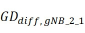


本公開的方面針對雙差分RTT方案,由此獲得兩個(或更多個)差分RTT測量值以用於目標UE的定位。例如,差分RTT測量之一可用於抵消(或至少減少)UE硬體群組延遲,而UE與無線節點(例如,gNB、或錨UE或其組合)之間的差分RTT測量的另一個可用於抵消(或至少減少)無線節點(例如,gNB、或錨UE或其組合)一側的殘差硬體群組延遲。這些方面可以提供各種技術優勢,諸如更精確的UE定位估計。此外,如本文所使用的,“硬體群組延遲”包括至少部分歸因於硬體的定時群組延遲(例如,其可能基於諸如溫度、濕度等的環境條件而變化),但可選地包括歸因於諸如軟體、韌體等因素的其他定時延遲。Aspects of the present disclosure are directed to a double differential RTT scheme whereby two (or more) differential RTT measurements are obtained for positioning of the target UE. For example, one of the differential RTT measurements may be used to offset (or at least reduce) UE hardware group delay, while the other of the differential RTT measurements between the UE and the wireless node (eg, gNB, or anchor UE, or a combination thereof) may be used to The residual hardware group delay on the side of the wireless node (eg, gNB, or anchor UE, or a combination thereof) is cancelled (or at least reduced). These aspects may provide various technical advantages, such as more accurate UE positioning estimation. Also, as used herein, "hardware group delay" includes timing group delays at least partially attributable to hardware (eg, which may vary based on environmental conditions such as temperature, humidity, etc.), but optionally Includes other timing delays due to factors such as software, firmware, etc.
圖16示出了根據本公開的方面的無線通信的示例性過程1600。在一個方面,過程1600可以由定位估計實體執行,該定位估計實體可對應于諸如UE 302的UE(例如,用於基於UE的定位)、諸如BS 304的BS或gNB(例如,用於積體在RAN中的LMF)或網路實體306(例如,諸如LMF的核心網路組件)。16 illustrates an
在1610處,定位估計實體(例如,接收器312或322或352或362、資料匯流排382、(一個或多個)網路介面380或390等)基於UE與第一無線節點之間的第一RTT測量和UE與第二無線節點之間的第二RTT測量來獲得第一差分RTT測量。在這種情況下,UE對應於期望對其進行定位估計的目標UE,並且第一和第二無線節點具有已知的位置。在一些設計中,第一和/或第二無線節點對應於gNB,而在其他設計中,第一和/或第二無線節點對應於UE(例如,靜態或半靜態的錨UE或參考UE和/或最近已經為其獲得了精確的定位估計的錨UE或參考UE)。At 1610, a location estimation entity (eg,
在1620處,定位估計實體(例如,接收器312或322或352或362、資料匯流排382、(一個或多個)網路介面380或390等)基於第三無線節點與第一無線節點之間的第三RTT測量和第三無線節點與第二無線節點之間的第四RTT測量來獲得第二差分RTT測量。在一些設計中,第三無線節點不必處於與UE的無線通信範圍內。在一些設計中,第三無線節點對應於gNB,而在其他設計中,第三無線節點可以對應於UE(例如,靜態或半靜態的錨UE或參考UE和/或最近已經為其獲得了精確的定位估計的錨UE或參考UE)。At 1620, a location estimation entity (eg,
在1630處,定位估計實體(例如,定位模組342或388或389、處理系統332或384或394等)至少部分地基於第一差分RTT測量和第二差分RTT測量來確定對UE的定位估計。下面更詳細地解釋1630的確定的算法示例。At 1630, a positioning estimation entity (eg,
圖17示出了根據本公開的方面的圖16的過程1600的示例實施方式1700。在圖17中,描述了第一無線節點1702、第二無線節點1704、UE 1706和第三無線節點1708。第一無線節點1702、第二無線節點1704、第三無線節點1708可以替代地分別表示為無線節點1、無線節點2和無線節點3,並且對應於關於圖16的過程1600所引用的第一、第二和第三無線節點。在圖17中,將第一無線節點1702與UE 1706之間的第一RTT測量1710表示為
RTT
1_UE ,將第二無線節點1704與UE 1706之間的第二RTT測量1712表示為
RTT
2_UE ,將第三無線節點1708與第一無線節點1702之間的第三RTT測量1714表示為
RTT
1_3 ,將第三無線節點1708與第二無線節點1704之間的第四RTT測量1716表示為
RTT
2_3 。第一RTT測量至第四RTT測量1710-1716對應於上面關於圖16的過程1600描述的第一RTT測量至第四RTT測量的示例。
17 illustrates an
圖18示出了根據本公開的另一方面的圖16的過程1600的示例實施方式1800。圖18的1802-1816類似於圖17的1702-1716,除了第一無線節點1702、第二無線節點1704和第三無線節點1708在圖18中分別被更具體地示出為gNB 1802、gNB 1804和gNB 1808之外。圖17和圖18在其他方面相同,並且因此圖18為簡潔起見,不作進一步討論。FIG. 18 illustrates an
圖19示出了根據本公開的另一方面的圖16的過程1600的示例實施方式1900。圖19的1902-1916類似於圖17的1702-1716,除了第一無線節點1702和第二無線節點1704在圖18中分別更具體地示出為gNB 1802和gNB 1804,並且第三無線節點1708在圖19中更具體地示出為UE 1908之外。圖17和圖19在其他方面相同,並且因此圖19為簡潔起見,不作進一步討論。FIG. 19 illustrates an
現在將更詳細地描述可作為圖1630的確定的一部分執行的計算的示例實施方式。在下面描述的示例算法中,為了便於解釋,相對於包括x和y坐標的二維(2D)坐標系來描述定位估計,並且其他方面可以替代地映射到在其他方面還包括z坐標的三維(3D)坐標系。可以如下導出第一與第二無線節點之間的差分硬體群組延遲:


然後可以如下抵消第一和第二無線節點的硬體群組延遲:

參考圖16,在一些設計中,第一差分RTT測量可以與第二差分RTT測量分開地由定位估計實體觸發。換句話說,RTT 1_3和RTT 2_3不需要與RTT 1_UE和RTT 2_UE聯合執行。在其他設計中,RTT 1_3和RTT 2_3可以與RTT 1_UE和RTT 2_UE聯合(或同時地)執行。例如,如果第三無線節點是靜態或半靜態的,則可以利用RTT 1_3和RTT 2_3的較舊值用於UE的定位估計,因為第三無線節點自採取這些測量以來不太可能移動太多(如果有的話)。因此,在一些設計中,可以在第一頻率處或基於第一觸發事件觸發第一差分RTT測量,並且可以在第二頻率處或基於第二觸發事件觸發第二差分RTT測量。在一些設計中,可以響應於確定執行對UE的定位估計而觸發第一差分RTT測量,並且響應於確定校準第一無線節點、第二無線節點或兩者的硬體群組延遲而觸發第二差分RTT測量。在其他設計中,可以通過確定執行對UE的定位估計來觸發第二差分RTT測量(或者換句話說,可以通過第一差分RTT測量來觸發第二差分RTT測量)。如上所述,不必針對每個UE定位估計校準第一和/或第二無線節點的硬體群組延遲(例如,特別是如果第三無線節點是靜態或半靜態的)。 Referring to FIG. 16, in some designs, the first differential RTT measurement may be triggered by the positioning estimation entity separately from the second differential RTT measurement. In other words, RTT 1_3 and RTT 2_3 need not be performed jointly with RTT 1_UE and RTT 2_UE . In other designs, RTT 1_3 and RTT 2_3 may be performed jointly (or concurrently) with RTT 1_UE and RTT 2_UE . For example, if the third wireless node is static or semi-static, the older values of RTT 1_3 and RTT 2_3 can be utilized for the UE's positioning estimation, since the third wireless node is unlikely to have moved much since taking these measurements ( if so). Thus, in some designs, a first differential RTT measurement may be triggered at a first frequency or based on a first trigger event, and a second differential RTT measurement may be triggered at a second frequency or based on a second trigger event. In some designs, a first differential RTT measurement may be triggered in response to determining to perform a position estimate for the UE, and a second differential RTT measurement may be triggered in response to determining to calibrate the hardware group delay of the first wireless node, the second wireless node, or both Differential RTT measurements. In other designs, the second differential RTT measurement may be triggered by determining to perform a positioning estimate for the UE (or in other words, the second differential RTT measurement may be triggered by the first differential RTT measurement). As mentioned above, it is not necessary to calibrate the hardware group delay of the first and/or second wireless node for each UE positioning estimate (eg, especially if the third wireless node is static or semi-static).
參考圖16,在一些設計中,在確定定位估計之前,第一、第二和第三無線節點與相應的已知位置相關聯。在一些設計中,第一、第二和第三無線節點包括一個或多個基站、一個或多個錨UE或其組合。在一些設計中,第一、第二和第三無線節點各自對應於相應的基站(例如,如圖18中所示)。在第一、第二和第三無線節點是諸如基站之類的固定節點的示例中,第三RTT測量可以基於第一無線節點與第三無線節點之間在一個或多個固定(或默認)波束上交換的一個或多個PRS,並且第四RTT測量基於第二無線節點與第三無線節點之間在至少一個固定(或默認)波束上交換的至少一個PRS,或其組合。在其他設計中,第一、第二和第三無線節點可以各自對應於相應的UE。在其他設計中,第一無線節點和第二無線節點對應於基站,而第三無線節點對應於與已知位置相關聯的錨UE(例如,如圖19所示)。在一些設計中,被分配用於確定錨UE的位置的定位資源大於用於確定對UE的定位估計的定位資源(例如,以確保錨UE具有非常精確的定位估計,因為該定位估計隨後被用於其他UE的定位)。Referring to FIG. 16, in some designs, the first, second, and third wireless nodes are associated with respective known positions prior to determining a positioning estimate. In some designs, the first, second, and third wireless nodes include one or more base stations, one or more anchor UEs, or a combination thereof. In some designs, the first, second, and third wireless nodes each correspond to respective base stations (eg, as shown in FIG. 18). In the example where the first, second and third wireless nodes are fixed nodes such as base stations, the third RTT measurement may be based on one or more fixed (or default) measurements between the first wireless node and the third wireless node The one or more PRSs exchanged on the beam, and the fourth RTT measurement is based on the at least one PRS exchanged between the second wireless node and the third wireless node on at least one fixed (or default) beam, or a combination thereof. In other designs, the first, second, and third wireless nodes may each correspond to respective UEs. In other designs, the first wireless node and the second wireless node correspond to a base station, while the third wireless node corresponds to an anchor UE associated with a known location (eg, as shown in FIG. 19 ). In some designs, the positioning resources allocated to determine the location of the anchor UE are larger than the positioning resources used to determine the positioning estimate for the UE (eg, to ensure that the anchor UE has a very accurate positioning estimate as it is then used positioning of other UEs).
參考圖16,在一些設計中,第三RTT測量可以基於從第三無線節點到第一無線節點的第一PRS和從第一無線節點到第三無線節點的第二PRS。在一些設計中,第一PRS和第二PRS與相同的PRS類型相關聯。在一些設計中,第一PRS和第二PRS包括至少一個單符號PRS、至少一個多符號PRS(例如,諸如傳統PRS)、或其組合。在一些設計中,第四RTT測量基於從第三無線節點到第二無線節點的第三PRS和從第二無線節點到第三無線節點的第四PRS。第一PRS可以與第三PRS相同或不同(例如,換句話說,在某些情況下,第一和第二無線節點都可以測量出相同的PRS),而第一PRS和第二PRS不同。在一些設計中,定位估計實體可以向第一和第三無線節點發送指示第一PRS是否跟隨第二PRS或者第二PRS是否跟隨第一PRS的訊息。在一些設計中,定位估計實體可以向第一和第三無線節點發送指示要用於第三RTT測量的初始PRS的PRS資源的訊息(例如,因為每個PRS可以與特定的Tx gNB和一個或多個Rx gNB相關聯)。在一些設計中,可以在雙向傳輸中使用相同類型的PRS,例如,定義了一類PRS,而不是Uu介面中的PRS和SRS。16, in some designs, the third RTT measurement may be based on a first PRS from the third wireless node to the first wireless node and a second PRS from the first wireless node to the third wireless node. In some designs, the first PRS and the second PRS are associated with the same PRS type. In some designs, the first PRS and the second PRS include at least one single-symbol PRS, at least one multi-symbol PRS (eg, such as legacy PRS), or a combination thereof. In some designs, the fourth RTT measurement is based on a third PRS from the third wireless node to the second wireless node and a fourth PRS from the second wireless node to the third wireless node. The first PRS may or may not be the same as the third PRS (eg, in other words, in some cases both the first and second wireless nodes may measure the same PRS), while the first and second PRS are different. In some designs, the positioning estimation entity may send a message to the first and third wireless nodes indicating whether the first PRS follows the second PRS or whether the second PRS follows the first PRS. In some designs, the positioning estimation entity may send a message to the first and third wireless nodes indicating the PRS resources of the initial PRS to be used for the third RTT measurement (eg, since each PRS may be associated with a specific Tx gNB and one or multiple Rx gNBs are associated). In some designs, the same type of PRS may be used in bidirectional transmission, eg, a class of PRS is defined instead of PRS and SRS in the Uu interface.
參考圖16,在一些設計中,每個PRS(例如,PRS ID)可以與一對gNB(TRP ID)相關聯,例如,每個PRS與特定的Tx/Rx gNB相關聯。在另一示例中,每個PRS可以從特定頻率層配置,該特定頻率層與特定公共參數(例如,中心頻率、開始PRB、BW、SCS、CP類型和梳大小)相關聯。每個PRS可以與一個Tx gNB和一個或多個Rx gNB相關聯。在一些設計中,可能存在用於(一個或多個)RTT測量的多個PRS資源之間的關聯。在一些設計中,至少一個PRS用於從gNB1到gNB2的傳輸,另一個PRS用於gNB2與gNB1之間的傳輸。這些PRS資源對可以與一個或多個RTT測量/報告相關聯。在一些設計中,如果PRS與一個Tx gNB和一個Rx gNB相關聯。在一些設計中,PRS可以與固定的窄波束相關聯(例如,在gNB可以是固定的時)。在一些設計中,如果Rx gNB知道兩個gNB之間的相對方向,則該Rx gNB可以基於該資訊導出Rx波束,從而可以減少或消除與波束管理相關的搜索。Referring to Figure 16, in some designs, each PRS (eg, PRS ID) may be associated with a pair of gNBs (TRP IDs), eg, each PRS is associated with a specific Tx/Rx gNB. In another example, each PRS may be configured from a specific frequency layer associated with specific common parameters (eg, center frequency, starting PRB, BW, SCS, CP type, and comb size). Each PRS may be associated with one Tx gNB and one or more Rx gNBs. In some designs, there may be an association between multiple PRS resources used for RTT measurement(s). In some designs, at least one PRS is used for transmissions from gNB1 to gNB2 and another PRS is used for transmissions between gNB2 and gNB1. These PRS resource pairs may be associated with one or more RTT measurements/reports. In some designs, if the PRS is associated with one Tx gNB and one Rx gNB. In some designs, the PRS may be associated with a fixed narrow beam (eg, when the gNB may be fixed). In some designs, if the Rx gNB knows the relative direction between the two gNBs, the Rx gNB can derive the Rx beam based on this information, which can reduce or eliminate searches related to beam management.
參考圖16,在一些設計中,第一、第二、第三和第四RTT測量和/或第一差分RTT測量和第二差分RTT測量經由一個或多個測量報告在定位估計實體處被接收。在一些設計中,對於相應的測量,該一個或多個測量報告各自指示發送接收點(TRP)識別碼、PRS源識別碼、PRS資源集ID、頻率層ID(例如,指示在其上進行相應的PRS測量的相應BW和頻率)、時間戳或其任何組合。16, in some designs, the first, second, third, and fourth RTT measurements and/or the first differential RTT measurement and the second differential RTT measurement are received at the positioning estimation entity via one or more measurement reports . In some designs, for a corresponding measurement, the one or more measurement reports each indicate a Transmit Receive Point (TRP) identification code, a PRS source identification code, a PRS resource set ID, a frequency layer ID (eg, indicating on which to make the corresponding measurement) the corresponding BW and frequency of the PRS measurements), timestamps, or any combination thereof.
參考圖16,在一些設計中,第一差分RTT測量基於UE與至少一個附加無線節點之間的至少一個附加RTT測量,第二差分RTT測量基於第三無線節點與一個或多個附加無線節點之間的一個或多個附加RTT測量,或其組合。例如,諸如
RTT
4_UE 、
RTT
5_UE 等的(一個或多個)附加RTT可用於導出UE 1的差分RTT測量,和/或諸如
RTT
4_3 、
RTT
5_3 等的(一個或多個)附加RTT可用於導出第三無線節點的差分RTT測量。
16, in some designs, the first differential RTT measurement is based on at least one additional RTT measurement between the UE and the at least one additional wireless node, and the second differential RTT measurement is based on the third wireless node and the one or more additional wireless nodes. one or more additional RTT measurements in between, or a combination thereof. For example, additional RTT(s) such as RTT 4_UE , RTT 5_UE , etc. may be used to derive differential RTT measurements for
參考圖16,在一些設計中,定位估計實體可以基於第四無線節點與第一無線節點之間的第五RTT測量和第四無線節點與第二無線節點之間的第六RTT測量來獲得第三差分RTT測量,定位估計還至少部分地基於第三差分RTT測量來確定。在這種情況下,定位估計還可以基於涉及不同無線節點對(例如,不同gNB對)的兩個其他差分RTT測量的另一個雙差分RTT測量。Referring to FIG. 16, in some designs, the location estimation entity may obtain the first RTT measurement based on the fifth RTT measurement between the fourth wireless node and the first wireless node and the sixth RTT measurement between the fourth wireless node and the second wireless node. Three differential RTT measurements, a position estimate is also determined based at least in part on the third differential RTT measurements. In this case, the location estimate may also be based on another double differential RTT measurement involving two other differential RTT measurements of different wireless node pairs (eg, different gNB pairs).
參考圖16,在一些設計中,定位估計實體可以從第一無線節點、第二無線節點或兩者接收第一硬體群組延遲校準能力的指示,並且響應於第一硬體群組延遲校準能力執行第二差分RTT測量。例如,第一硬體群組延遲校準能力可以是動態指示或靜態或半靜態指示。在一些設計中,可以基於單個差分RTT測量來確定另一UE的另一定位估計,該單個差分RTT測量基於涉及與第二硬體群組延遲校準能力相關聯的另一定位估計,該第二硬體群組延遲校準能力比第一硬體組延遲校準能力更精確。換句話說,在一些設計中,多個差分RTT測量被專門用於在第一與第二無線節點之間期望某種程度的硬體群組延遲校準的場景,並且在其他場景中可以被跳過(例如,最近的硬體群組延遲校準已經是已知的等等)。16, in some designs, the positioning estimation entity may receive an indication of the first hardware group delay calibration capability from the first wireless node, the second wireless node, or both, and be responsive to the first hardware group delay calibration Ability to perform a second differential RTT measurement. For example, the first hardware group delay calibration capability may be a dynamic indication or a static or semi-static indication. In some designs, another positioning estimate for another UE may be determined based on a single differential RTT measurement based on another positioning estimate associated with a second hardware group delay calibration capability, the second The hardware group delay calibration capability is more accurate than the first hardware group delay calibration capability. In other words, in some designs, multiple differential RTT measurements are dedicated to scenarios where some degree of hardware group delay calibration is desired between the first and second wireless nodes, and can be skipped in other scenarios (eg, the most recent hardware group delay calibration is already known, etc.).
參考圖16,硬體群組延遲校準能力可以經由一次性能力報告來指示。例如,相應無線節點(例如,gNB)可以報告高精度群組延遲校準能力,這可以提示定位估計實體跳過涉及該相應無線節點的用於硬體群組延遲校準的差分RTT測量。在另一示例中,可以動態地指示硬體群組延遲校準能力。例如,硬體群組延遲校準誤差會隨著一些因素(例如,時間、頻率、BW、溫度等)而改變。因此,相應的無線節點(例如,gNB)可以動態地指示硬體群組延遲校準的相應精度級別。在一些設計中,可以定義多個級別的硬體群組延遲校準精度,並且相應的無線節點(例如,gNB)可以動態地報告硬體群組校準精度級別。例如,如果相應的硬體群組延遲校準誤差大(例如,高於閾值),則相應的無線節點可以指示LMF應該在雙差分RTT過程中包括該相應的無線節點。在另一示例中,相應的無線節點(例如,gNB)可以動態地指示是否需要雙差分RTT,而不報告其相應的硬體群組延遲校準精度水平。在一些設計中,定位估計實體(例如,LMF)可以基於兩組無線節點(例如,gNB)的硬體群組延遲校準能力來對它們進行分類。例如,具有高精度硬體群組延遲校準的無線節點(例如,gNB)可以進行基於規則RTT或差分RTT的UE定位,並且具有低精度硬體群組延遲校準的無線節點(例如,gNB)可以進行基於雙差分RTT的UE定位。Referring to Figure 16, the hardware group delay calibration capability may be indicated via a one-time capability report. For example, a corresponding wireless node (eg, gNB) may report a high precision group delay calibration capability, which may prompt the positioning estimation entity to skip differential RTT measurements for hardware group delay calibration involving the corresponding wireless node. In another example, the hardware group delay calibration capability may be dynamically indicated. For example, the hardware group delay calibration error can vary with a number of factors (eg, time, frequency, BW, temperature, etc.). Accordingly, the corresponding wireless node (eg, gNB) can dynamically indicate the corresponding level of accuracy of the hardware group delay calibration. In some designs, multiple levels of hardware group delay calibration accuracy may be defined, and corresponding wireless nodes (eg, gNBs) may dynamically report the hardware group calibration accuracy levels. For example, if the corresponding hardware group delay calibration error is large (eg, above a threshold), the corresponding wireless node may indicate that the LMF should include the corresponding wireless node in the double differential RTT process. In another example, the corresponding wireless node (eg, gNB) may dynamically indicate whether double differential RTT is required without reporting its corresponding hardware group delay calibration accuracy level. In some designs, a positioning estimation entity (eg, LMF) may classify two sets of wireless nodes (eg, gNBs) based on their hardware group delay calibration capabilities. For example, a wireless node (eg, gNB) with high precision hardware group delay calibration may perform regular RTT or differential RTT based UE positioning, and a wireless node (eg, gNB) with low precision hardware group delay calibration may Perform UE positioning based on double differential RTT.
參考圖16,在一些設計中,定位估計實體可以從第一無線節點、第二無線節點或兩者接收以觸發用於硬體群組延遲校準的第二差分RTT測量的請求。16, in some designs, the position estimation entity may receive a request from the first wireless node, the second wireless node, or both to trigger a second differential RTT measurement for hardware group delay calibration.
參考圖16,在一些設計中,定位估計實體可以基於一個或多個參數選擇用於經由第二RTT差分測量的第一和第二無線節點的硬體群組延遲校準的第三無線節點。在一些設計中,一個或多個參數可以包括第三無線節點與第一和第二無線節點之間的通道狀況。在一些設計中,如果第一、第二和第三無線節點中的每一個是固定節點,則對第三無線節點的選擇是預定的。在其他設計中,如果第一、第二和第三無線節點中的一個或多個節點是行動節點,則第三無線節點的選擇是動態的。然而,在一些設計中,這些參數可用於無線節點選擇,甚至用於除了更多的行動錨UE之外的固定gNB。例如,在第一、第二和第三無線節點對應於密集部署(例如,城市環境)中的固定gNB的場景中,gNB之間可能存在阻塞,特別是在FR2中。16, in some designs, the positioning estimation entity may select a third wireless node for hardware group delay calibration of the first and second wireless nodes via the second RTT differential measurement based on one or more parameters. In some designs, the one or more parameters may include channel conditions between the third wireless node and the first and second wireless nodes. In some designs, the selection of the third wireless node is predetermined if each of the first, second, and third wireless nodes is a fixed node. In other designs, if one or more of the first, second, and third wireless nodes are active nodes, the selection of the third wireless node is dynamic. However, in some designs, these parameters may be used for radio node selection, even for fixed gNBs other than more mobile anchor UEs. For example, in a scenario where the first, second and third wireless nodes correspond to fixed gNBs in a dense deployment (eg, urban environment), there may be blocking between gNBs, especially in FR2.
如上所述,第三無線節點(其可被視為“參考”無線節點,可以用於校準兩個其他無線節點的硬體群組延遲)可以對應於具有已知位置的任何無線節點類型(例如,gNB或UE)。在針對第三無線節點的UE實施方式的情況下,該“參考UE”可以是行動的,並且與諸如gNB的其他無線節點類型一樣,通常在位置上保持較不固定。因此,與使用gNB作為第三無線節點相比,用於第三無線節點的參考UE可能與更多的殘差定位誤差相關聯(例如,由於隨時間變化的通道狀況)。As mentioned above, the third wireless node (which can be considered a "reference" wireless node that can be used to calibrate the hardware group delay of the two other wireless nodes) can correspond to any wireless node type with a known location (eg , gNB or UE). In the case of a UE implementation for the third wireless node, this "reference UE" may be mobile and, like other wireless node types such as gNBs, generally remain less fixed in location. Therefore, the reference UE for the third radio node may be associated with more residual positioning errors (eg, due to time-varying channel conditions) than using the gNB as the third radio node.
因此,本公開的各方面針對實現涉及參考UE的一個或多個位置估計方案。在一些方面,可以迭代獲得參考UE的位置,其中結合至少一個雙差分RTT測量過程(例如,如圖16)將最近迭代獲得的參考UE的位置用於對目標UE的定位估計。在其他方面,可以在參考UE群組中選擇主參考UE,其中該群組中的任何參考UE能夠執行與用於目標UE的定位估計過程相關聯的差分RTT測量。在這種情況下,可以迭代獲得主參考UE的位置,並使用該位置來細化群組中的(一個或多個)其他參考UE的(一個或多個)位置。(可一起部署或單獨部署的)任一場景可以提供各種技術優勢,諸如通過更精確地跟蹤參考UE來改進目標UE的定位精度,該參考UE用於導出用於對目標UE的定位估計的無線節點的硬體群組校準的差分RTT測量。Accordingly, aspects of the present disclosure are directed to implementing one or more location estimation schemes involving a reference UE. In some aspects, the location of the reference UE may be obtained iteratively, wherein the most recently iteratively obtained location of the reference UE is used in the location estimation of the target UE in conjunction with at least one double differential RTT measurement process (eg, as shown in FIG. 16 ). In other aspects, the primary reference UE may be selected in a reference UE group, wherein any reference UE in the group is capable of performing differential RTT measurements associated with the positioning estimation process for the target UE. In this case, the location of the primary reference UE can be obtained iteratively and used to refine the location of the other reference UE(s) in the group. Either scenario (deployable together or separately) may provide various technical advantages, such as improving the location accuracy of the target UE by more accurately tracking the reference UE used to derive the radio for the location estimate of the target UE. The node's hardware group calibrated differential RTT measurement.
圖20示出了根據本公開的方面的無線通信的示例性過程2000。在一個方面,過程2000可以由定位估計實體執行,該定位估計實體可對應于諸如UE 302的UE(例如,用於基於UE的定位)、諸如BS 304的BS或gNB(例如,用於積體在RAN中的LMF)或網路實體306(例如,諸如LMF的核心網路組件)。更具體地,過程2000對應於圖16的過程1600的示例實施方式,其中第三無線節點對應於參考UE(例如,UE 302),對於該參考UE(例如,迭代地)獲得位置,並將該位置用於在1630處確定定位估計(例如,如圖19中所描述的)。20 illustrates an
在2010處,定位估計實體(例如,接收器312或322或352或362、資料匯流排382、(一個或多個)網路介面380或390、處理系統332、384或394、定位模組342、388或389等)獲得參考UE的位置。在一些設計中,可以迭代地(例如,以某個間隔或週期)獲得參考UE的位置。At 2010, a location estimation entity (eg,
在2020處,定位估計實體(例如,接收器312或322或352或362、資料匯流排382、(一個或多個)網路介面380或390等)基於目標UE與第一無線節點之間的第一往返時間(RTT)測量和目標UE與第二無線節點之間的第二RTT測量來獲得第一差分RTT測量。在這種情況下,UE對應於期望對其進行定位估計的目標UE,並且第一和第二無線節點具有已知的位置。在一個示例中,2020是圖16的1610的示例實施方式。At 2020, a location estimation entity (eg,
在2030處,定位估計實體(例如,接收器312或322或352或362、資料匯流排382、(一個或多個)網路介面380或390等)基於參考UE與第一無線節點之間的第三RTT測量和參考UE與第二無線節點之間的第四RTT測量來獲得第二差分RTT測量。在一些設計中,參考UE不必處於與目標UE的無線通信範圍內。在一個示例中,2030是圖16的1620的示例實施方式。At 2030, a location estimation entity (eg,
在2040處,定位估計實體(例如,定位模組342或388或389、處理系統332或384或394等)至少部分地基於第一差分RTT測量和第二差分RTT測量和從2021獲得的參考UE的位置來確定對目標UE的定位估計。在示例中,可以基於最近迭代獲得的參考UE的位置來確定2040處的定位估計。At 2040, a positioning estimation entity (eg,
現在將更詳細地描述可作為圖20的2040的確定的一部分執行的計算的示例實施方式。在下面描述的示例算法中,為了便於解釋,相對於包括x和y坐標的二維(2D)坐標系來描述定位估計,並且其他方面可以替代地映射到在其他方面還包括z坐標的三維(3D)坐標系。參考圖19,UE 1906(或“目標UE”)可以被表示為
UE:T,並且UE 1908(或“參考UE”)可以被表示為
UE:R。可以如下導出第一與第二無線節點之間的差分硬體群組延遲:


然後可以如下抵消第一和第二無線節點的硬體群組延遲:

與等式7-11不同,在等式12-16中,目標UE位置和參考UE的位置都可以是未知的。在這種情況下,可以對目標UE位置和參考UE的位置進行聯合估計,參考UE的位置對應于如上文關於圖20的2010所述的迭代獲得的參考UE的位置的最近迭代。Unlike Equations 7-11, in Equations 12-16, both the target UE location and the reference UE location may be unknown. In this case, a joint estimation of the target UE location and the location of the reference UE may be performed, the location of the reference UE corresponding to the most recent iteration of the location of the reference UE obtained iteratively as described above with respect to 2010 of FIG. 20 .
參考圖20,在一些設計中,定位估計實體可以初始選擇參考UE並確定在圖20的2010的第0次迭代處的初始位置


參考圖20,在一些設計中,響應於確定估計目標UE的定位而觸發2010處的(例如,迭代)獲得參考UE的位置。在這種情況下,可以根據需要觸發2010以節約參考UE處的功率。在一些設計中,該第一、第二、第三和第四RTT測量在彼此的閾值時間段內(例如,聯合地或近似聯合地)執行。例如,如上所述,閾值時間段小於獲得參考UE的位置的迭代之間的間隔(例如,使得在迭代i-1處的參考UE的位置用於在第i次迭代處的硬體群組校準)。20, in some designs, obtaining the location of the reference UE at 2010 is triggered (eg, iteratively) in response to determining the location of the estimated target UE. In this case, 2010 can be triggered as needed to save power at the reference UE. In some designs, the first, second, third, and fourth RTT measurements are performed within a threshold time period of each other (eg, jointly or approximately jointly). For example, as described above, the threshold time period is less than the interval between iterations in which the position of the reference UE is obtained (eg, such that the position of the reference UE at iteration i-1 is used for the hardware group calibration at iteration i ).
參考圖20,在一些設計中,參考UE的位置經由新無線電(NR)定位技術或非NR定位技術(例如,GPS等)來(例如,迭代地)獲得。在一些設計中,定位估計實體還可以部分地基於以下中的一個或多個或其任何組合來細化參考UE的位置:第一和/或第二差分RTT測量、第一、第二、第三和/或第四RTT測量、對目標UE的定位估計。換句話說,參考UE的位置可用於經由硬體群組延遲校準來細化目標UE的定位估計,並且進而可經由對目標UE的定位估計來細化參考UE的位置。在一些設計中,目標UE可以轉換到另一個參考UE,並且然後該另一個參考UE可以用於一個或多個其他目標UE的基於雙差分RTT的定位。例如,在圖20的過程的多次迭代之後,目標UE位置的精度可以超過精度閾值(例如,足夠好以有資格作為參考UE)。在一些設計中,定位估計實體可以做出關於目標UE是否有資格成為參考UE的確定(例如,目標UE可以報告其測量品質或通道狀況指示,以促進定位估計實體做出該決定)。因此,任何目標UE到參考UE的轉換可以響應於目標UE的定位估計精度超過閾值、來自目標UE的指示測量品質或通道狀況的測量資訊或其任何組合。20, in some designs, the location of the reference UE is obtained (eg, iteratively) via new radio (NR) positioning techniques or non-NR positioning techniques (eg, GPS, etc.). In some designs, the location estimation entity may also refine the location of the reference UE based in part on one or more or any combination of the following: first and/or second differential RTT measurements, first, second, first The third and/or fourth RTT measurements, positioning estimation of the target UE. In other words, the location of the reference UE may be used to refine the location estimate of the target UE via hardware group delay calibration, and in turn may refine the location of the reference UE via the location estimate of the target UE. In some designs, the target UE may transition to another reference UE, and the other reference UE may then be used for double differential RTT-based positioning of one or more other target UEs. For example, after multiple iterations of the process of Figure 20, the accuracy of the target UE location may exceed an accuracy threshold (eg, good enough to qualify as a reference UE). In some designs, the positioning estimation entity may make a determination as to whether the target UE qualifies as a reference UE (eg, the target UE may report its measurement quality or channel status indication to facilitate the positioning estimation entity making this determination). Thus, any target UE to reference UE transition may be in response to the target UE's positioning estimation accuracy exceeding a threshold, measurement information from the target UE indicating measurement quality or channel conditions, or any combination thereof.
參考圖20,在一些設計中,響應於至少一個觸發事件,可以停止在2010處(例如,迭代地)獲得參考UE的位置。例如,該至少一個觸發事件可以包括:達到閾值迭代數量、對參考UE的定位估計精度(例如,平均誤差和誤差方差等)提高到高於精度閾值、目標UE和參考UE的定位估計收斂(例如,對於最後N次迭代,對目標UE和參考UE的位置估計具有在閾值內的變化,例如亞米級)、確定從參考UE切換到另一參考UE或其任何組合。在一些設計中,至少一個觸發事件包括:確定從參考UE切換到另一參考UE,以及結合所述停止,定位估計實體開始(或繼續)迭代獲得另一參考UE的位置。例如,參考UE的通道狀況可以部分由於參考UE的行動性而隨時間變化。因此,可以在迭代之間將參考UE切換到另一UE(例如,對於新的參考UE重新開始圖20的過程)。例如,如果當前參考UE的通道狀況不能提供高於精度閾值的精度,則可以向定位估計實體發送通知。可替代地,網路可以監視來自參考UE的UL信號以估計參考UE的通道狀況,然後將其報告給定位估計實體。在任一情況下,定位估計實體可以響應於這樣的通道估計資料而做出切換參考UE的決定。例如,如果多個參考UE可用,則定位估計實體在2010的一個或多個迭代之後做出切換的決定。定位估計實體還可以對多個參考UE(或參考gNB)通道進行平均,以減少由於一個或多個RTT測量而產生的偏置。Referring to FIG. 20, in some designs, in response to at least one triggering event, obtaining the location of the reference UE may cease (eg, iteratively) at 2010. For example, the at least one trigger event may include: reaching a threshold number of iterations, improving the accuracy of the positioning estimation for the reference UE (eg, mean error and error variance, etc.) above an accuracy threshold, convergence of the positioning estimates of the target UE and the reference UE (eg, , for the last N iterations, the location estimates for the target UE and the reference UE have variations within a threshold, eg sub-meter), determine the handover from the reference UE to another reference UE, or any combination thereof. In some designs, the at least one triggering event includes determining to handover from the reference UE to another reference UE, and in conjunction with the stopping, the positioning estimation entity begins (or continues) iteratively obtaining the position of the other reference UE. For example, the channel conditions of the reference UE may vary over time due in part to the mobility of the reference UE. Therefore, the reference UE may be handed over to another UE between iterations (eg, the process of FIG. 20 is restarted for the new reference UE). For example, if the channel conditions of the current reference UE do not provide accuracy above the accuracy threshold, a notification may be sent to the positioning estimation entity. Alternatively, the network may monitor the UL signal from the reference UE to estimate the channel conditions of the reference UE and then report this to the positioning estimation entity. In either case, the positioning estimation entity may make the decision to switch the reference UE in response to such channel estimation data. For example, if multiple reference UEs are available, the positioning estimation entity makes a decision to handover after one or more iterations of 2010. The positioning estimation entity may also average multiple reference UE (or reference gNB) channels to reduce bias due to one or more RTT measurements.
參考圖20,在一些設計中,可以針對2010的每次迭代執行2020-2040。在其他設計中,可以針對少於2010的所有迭代來執行2020-2040(例如,可以關於目標UE的定位估計跳過針對參考UE的位置估計的一些迭代)。20, in some designs, 2020-2040 may be performed for each iteration of 2010. In other designs, 2020-2040 may be performed for all iterations less than 2010 (eg, some iterations of the location estimation for the reference UE may be skipped with respect to the location estimation of the target UE).
參考圖20,在一些設計中,定位估計實體還可以在迭代獲得參考UE的位置的同時迭代獲得另一參考UE的位置。例如,定位估計實體還可以基於另一參考UE與第一無線節點之間的第五往返時間(RTT)測量和另一參考UE與第二無線節點之間的第六RTT測量來獲得第三差分RTT測量,並且對目標UE的定位估計還至少部分地基於該第三差分RTT測量。換句話說,除了基於“雙”差分RTT的定位的參考UE之外,多個參考UE可以被激活用於基於雙差分RTT的定位。Referring to FIG. 20, in some designs, the location estimation entity may also iteratively obtain the location of another reference UE while iteratively obtaining the location of the reference UE. For example, the positioning estimation entity may also obtain a third differential based on a fifth round trip time (RTT) measurement between the other reference UE and the first wireless node and a sixth RTT measurement between the other reference UE and the second wireless node RTT measurements are made, and the location estimate for the target UE is also based, at least in part, on the third differential RTT measurement. In other words, in addition to the reference UE for "dual" differential RTT based positioning, multiple reference UEs may be activated for dual differential RTT based positioning.
參考圖20,在一些設計中,在確定定位估計之前,第一和第二無線節點與相應的已知位置相關聯。在一些設計中,第一和第二無線節點包括一個或多個基站、一個或多個錨UE或其組合。在一些設計中,第一和第二無線節點各自對應於相應的基站。在其他設計中,第一和第二無線節點各自對應於相應的UE。在另外其他設計中,第一無線節點可以對應於基站,而第二無線節點可以對應於錨UE(反之亦然)。在一些設計中,被分配用於在2010處確定獲得的參考UE的位置(例如,迭代獲得的參考UE的位置中的至少一個)的定位資源大於用於確定對UE的定位估計的定位資源(例如,以確保參考UE具有非常精確的定位估計,因為該定位估計隨後被用於其他目標UE的定位)。Referring to FIG. 20, in some designs, the first and second wireless nodes are associated with respective known positions prior to determining a positioning estimate. In some designs, the first and second wireless nodes include one or more base stations, one or more anchor UEs, or a combination thereof. In some designs, the first and second wireless nodes each correspond to respective base stations. In other designs, the first and second wireless nodes each correspond to respective UEs. In yet other designs, the first wireless node may correspond to a base station and the second wireless node may correspond to an anchor UE (or vice versa). In some designs, the positioning resources allocated for determining the obtained position of the reference UE at 2010 (eg, at least one of the iteratively obtained positions of the reference UE) are greater than the positioning resources used for determining the positioning estimate for the UE ( For example, to ensure that the reference UE has a very accurate positioning estimate, as this is then used for the positioning of other target UEs).
參考圖20,在一些設計中,第一、第二、第三和第四RTT測量和/或第一差分RTT測量和第二差分RTT測量經由一個或多個測量報告在定位估計實體處被接收。例如,對於相應的測量,一個或多個測量報告可以各自指示發送接收點(TRP)識別碼、定位參考信號(PRS)源識別碼、PRS資源集ID、頻率層ID、時間戳或其任何組合。20, in some designs, the first, second, third, and fourth RTT measurements and/or the first differential RTT measurement and the second differential RTT measurement are received at the positioning estimation entity via one or more measurement reports . For example, for a corresponding measurement, one or more measurement reports may each indicate a transmit receive point (TRP) identity, a positioning reference signal (PRS) source identity, a PRS resource set ID, a frequency layer ID, a timestamp, or any combination thereof .
參考圖20,在一些設計中,第一差分RTT測量基於目標UE與至少一個附加無線節點之間的至少一個附加RTT測量,第二差分RTT測量基於參考UE與一個或多個附加無線節點之間的一個或多個附加RTT測量,或其組合。例如,諸如
RTT
4_UE:T 、
RTT
5_UE:T 等的(一個或多個)附加RTT可用於導出UE 1的差分RTT測量,和/或諸如
RTT
4_UE:R 、
RTT
5_UE:R 等的(一個或多個)附加RTT可用於導出參考UE的差分RTT測量。(一個或多個)附加無線節點可以包括(一個或多個)附加參考gNB、(一個或多個)附加參考UE、或其組合。
20, in some designs, the first differential RTT measurement is based on at least one additional RTT measurement between the target UE and at least one additional wireless node, and the second differential RTT measurement is based on the reference UE and the one or more additional wireless nodes. one or more additional RTT measurements, or a combination thereof. For example, additional RTT(s) such as RTT 4_UE:T , RTT 5_UE:T , etc. may be used to derive differential RTT measurements for
圖21示出了根據本公開的方面的無線通信的示例性過程2100。在一個方面,過程2100可以由定位估計實體執行,該定位估計實體可對應于諸如UE 302的UE(例如,用於基於UE的定位)、諸如BS 304的BS或gNB(例如,用於積體在RAN中的LMF)或網路實體306(例如,諸如LMF的核心網路組件)。在一些設計中,過程2100可以與圖16和圖20的過程1600和/或2000結合執行。在其他設計中,過程2100可以作為後臺進程來執行,以保持高度精確的參考UE的位置,即使在圖16和圖20的過程1600和/或2000沒被活躍地執行時也是如此。21 illustrates an
在2110處,定位估計實體(例如,處理系統332、384或394、定位模組342、388或389等)從多個參考UE中選擇主參考UE,該多個參考UE能夠執行與目標UE的定位估計過程相關聯的差分RTT測量。At 2110, a positioning estimation entity (eg,
在2120處,定位估計實體(例如,接收器312或322或352或362、資料匯流排382、(一個或多個)網路介面380或390、處理系統332、384或394、定位模組342、388或389等)獲得主參考UE的位置。在一些設計中,可以迭代地(例如,以某個間隔或週期)獲得主參考UE的位置。如上所述,在一些設計中,可以獨立於目標UE的位置估計的發起來觸發(例如,迭代地)獲得主參考UE的位置。例如,在一組參考UE中,定位估計實體可以選擇主參考UE,其被表示為


在2130處,定位估計實體(例如,定位模組342或388或389、處理系統332或384或394等)至少部分地基於所獲得的主參考UE的位置(例如,迭代獲得的主參考UE的位置中的最新位置)來確定多個參考UE中的一個或多個其他參考UE的位置。例如,在第i次迭代處,基於主參考UE的位置的先前估計位置


參考圖21,在一些設計中,主參考UE的位置經由新無線電(NR)定位技術或非NR定位技術(例如,GPS等)來(例如,迭代地)獲得。在一些設計中,定位估計實體可以部分地基於與一個或多個其他參考UE的位置的確定相關聯的測量資訊來細化主參考UE的位置。在一些方面,定位估計實體可以響應於至少一個觸發事件而停止2010處的迭代獲得主參考UE的位置。在一些設計中,所述至少一個觸發事件可以包括:達到閾值迭代數量、主參考UE的定位估計精度(例如,平均誤差和誤差方差)提高到高於精度閾值、主參考UE和一個或多個其他參考UE的定位估計收斂(例如,對於最後N次迭代,主參考UE和(一個或多個)參考UE的位置估計具有閾值內的變化,例如,亞米級)、確定將不同的參考UE提升到主參考UE,或其組合。在一些設計中,至少一個觸發事件包括確定將該不同的參考UE提升到主參考UE,並且結合所述停止,定位估計實體可以開始(或繼續)迭代獲得所提升的主參考UE的位置。21, in some designs, the location of the primary reference UE is obtained (eg, iteratively) via new radio (NR) positioning techniques or non-NR positioning techniques (eg, GPS, etc.). In some designs, the location estimation entity may refine the location of the primary reference UE based in part on measurement information associated with the determination of the location of one or more other reference UEs. In some aspects, the location estimation entity may stop iterating at 2010 to obtain the location of the primary reference UE in response to the at least one triggering event. In some designs, the at least one trigger event may include reaching a threshold number of iterations, an improvement in the accuracy of the positioning estimation (eg, mean error and error variance) of the primary reference UE above an accuracy threshold, the primary reference UE, and one or more The positioning estimates of the other reference UEs converge (eg, for the last N iterations, the position estimates of the primary reference UE and the reference UE(s) have variations within a threshold, eg, sub-meter), determine that the different reference UEs will be Promoted to the primary reference UE, or a combination thereof. In some designs, the at least one triggering event includes determining to promote the dissimilar reference UE to the primary reference UE, and in conjunction with the stopping, the positioning estimation entity may begin (or continue) iteratively obtain the position of the promoted primary reference UE.
參考圖21,在一些設計中,定位估計實體還可以確定多個參考UE的子集能夠按群組進行定位估計收斂。在一個示例中,只有屬該子集的參考UE被用於與用於目標UE的定位估計過程相關聯的差分RTT測量。例如,圖21的過程2100可以包括對TRP群組中的參考UE上的(一個或多個)PRS的掃描。在掃描的每一輪(或每次迭代)處,可選地選擇新的主參考UE,從而觸發圖21的過程2100的重新開始。在一些設計中,在掃描的多輪(或多次迭代)之後,一些或所有參考UE的位置估計可以收斂。如果一個或多個參考UE高度行動(例如,快速移動)和/或受到大量通道狀況變化的影響,則按群組進行估計可能具有挑戰性。在這種情況下,可以排除這樣的參考UE,並且可以選擇能夠實現按群組進行定位估計收斂的參考UE的子群組。然後可以選擇或推薦該子群組作為用於目標UE的基於雙差分RTT的定位的參考節點。Referring to FIG. 21, in some designs, the positioning estimation entity may also determine that a subset of multiple reference UEs are capable of positioning estimation convergence by group. In one example, only reference UEs belonging to this subset are used for differential RTT measurements associated with the positioning estimation process for the target UE. For example, the
在上面的詳細描述中,可以看到不同的特徵在示例中被分組在一起。這種公開方式不應被理解為示例條款具有比每個條款中明確提到的更多特徵的意圖。相反,本公開的各個方面可以包括比所公開的單個示例條款的所有特徵更少的特徵。因此,以下條款應被視為包含在說明書中,其中每個條款本身可以作為一個單獨的示例。雖然每個從屬條款可以在條款中提到與其他條款之一的特定組合,但該從屬條款的(一個或多個)方面並不限於該特定組合。應當理解,其他示例條款還可以包括(一個或多個)從屬條款方面與任何其他從屬條款或獨立條款的主題的組合,或者包括與其他從屬和獨立條款的任何特徵的組合。本文公開的各個方面明確地包括這些組合,除非明確地表示或可以容易地推斷不意圖進行的特定組合(例如,矛盾的方面,諸如將元件定義為絕緣體和導體)。此外,它還意在一個條款的各方面可以包括在任何其他獨立條款中,即使該條款並不直接依賴於獨立條款。In the detailed description above, it can be seen that different features are grouped together in the examples. This manner of disclosure should not be construed as an intent that the example clauses have more features than are expressly mentioned in each clause. Rather, various aspects of the present disclosure may include fewer than all features of a single example clause disclosed. Accordingly, the following clauses should be deemed to be included in the specification, each of which may itself serve as a separate example. Although each sub-clause may refer in a clause to a particular combination with one of the other clauses, the aspect(s) of that sub-clause is not limited to that particular combination. It should be understood that other example clauses may also include the aspect(s) of the dependent clause in combination with the subject matter of any other dependent or independent clause, or with any feature of the other dependent and independent clause. The various aspects disclosed herein expressly include such combinations unless expressly stated or readily inferred that a specific combination is not intended (eg, contradictory aspects, such as defining an element as an insulator and a conductor). Furthermore, it is intended that aspects of a clause may be included in any other independent clause, even if the clause does not directly depend on the independent clause.
條款1.一種對定位估計實體進行操作的方法包括:獲得參考用戶設備(UE)的位置;基於目標UE與第一無線節點之間的第一往返時間(RTT)測量和目標UE與第二無線節點之間的第二RTT測量,獲得第一差分RTT測量;基於參考UE與第一無線節點之間的第三RTT測量和參考UE與第二無線節點之間的第四RTT測量,獲得第二差分RTT測量;以及至少部分地基於第一差分RTT測量和第二差分RTT測量以及所獲得的參考UE的位置來確定對目標UE的定位估計。
條款2.根據條款1的方法,其中,響應於確定估計目標UE的定位而觸發獲得參考UE的位置。
條款3.根據條款1至條款2中的任何一項的方法,其中,該第一、第二、第三和第四RTT測量在彼此的閾值時間段內執行。
條款4.根據條款3的方法,其中該閾值時間段小於獲得參考UE的位置的迭代之間的間隔。
條款5.根據條款1至條款4中的任何一項的方法,其中,參考UE的位置經由新無線電(NR)定位技術或非NR定位技術獲得。
條款6.根據條款1至條款5中的任何一項的方法,還包括:部分地基於以下一個或多個或其任何組合來細化參考UE的位置:第一和/或第二差分RTT測量、第一、第二、第三和/或第四RTT測量、對目標UE的定位估計。
條款7.根據條款1至條款6中的任何一項的方法,還包括:將目標UE轉換到另一參考UE,其中,該另一參考UE被用於一個或多個其他目標UE的基於雙差分RTT的定位。
條款8.根據條款7的方法,其中,該轉換響應於目標UE的定位估計精度超過閾值、來自目標UE的指示測量品質或通道狀況的測量資訊或其任何組合。
條款9.根據條款1至條款8中的任何一項的方法,其中,迭代獲得參考UE的位置,並且其中,基於最近迭代獲得的參考UE的位置確定對目標UE的定位估計。
條款10.在根據條款9的方法,還包括:響應於至少一個觸發事件,停止對參考UE的位置的迭代獲得。
條款11.根據條款10的方法,其中,該至少一個觸發事件包括:達到閾值迭代數量、參考UE的定位估計精度提高到高於精度閾值、目標UE和參考UE的定位估計收斂、確定從參考UE切換到另一參考UE,或其任何組合。
條款12.根據條款11的方法,其中,至少一個觸發事件包括確定從該參考UE切換到另一參考UE,還包括:結合所述停止,迭代獲得另一參考UE的位置。
條款13.根據條款10至條款12的任何一項的方法,還包括:在迭代獲得參考UE的位置的同時迭代獲得另一參考UE的位置,還包括:基於另一參考UE與第一無線節點之間的第五往返時間(RTT)測量和另一參考UE與第二無線節點之間的第六RTT測量來獲得第三差分RTT測量,其中,目標UE的定位估計還至少部分地基於該第三差分RTT測量。
條款14.根據條款1至條款13中的任何一項的方法,其中,第一和第二無線節點在確定該定位估計之前與相應的已知位置相關聯。Clause 14. The method of any of
條款15.根據條款1至條款14中的任何一項的方法,其中,第一和第二無線節點包括一個或多個基站、一個或多個錨UE或其組合。Clause 15. The method of any of
條款16.根據條款15的方法,其中,第一和第二無線節點各自對應於相應的基站。Clause 16. The method of clause 15, wherein the first and second wireless nodes each correspond to respective base stations.
條款17.根據條款15或條款16中的任何一項的方法,其中,第一和第二無線節點各自對應於相應的UE。Clause 17. The method of any of clauses 15 or 16, wherein the first and second wireless nodes each correspond to respective UEs.
條款18.根據條款1至條款17中的任何一項的方法,其中,被分配用於確定所獲得的參考UE的位置的定位資源大於用於確定該UE的定位估計的定位資源。
條款19.根據條款1至條款18中的任何一項的方法,其中,第一、第二、第三和第四RTT測量和/或第一差分RTT測量和第二差分RTT測量經由一個或多個測量報告在定位估計實體處被接收。Clause 19. A method according to any of
條款20.根據條款19的方法,其中,對於相應的測量,一個或多個測量報告各自指示發送接收點(TRP)識別碼、定位參考信號(PRS)源識別碼、PRS資源集ID、頻率層ID、時間戳或其任何組合。Clause 20. The method of clause 19, wherein, for a corresponding measurement, the one or more measurement reports each indicate a transmit reception point (TRP) identity, a positioning reference signal (PRS) source identity, a PRS resource set ID, a frequency layer ID, timestamp, or any combination thereof.
條款21.根據條款1至條款20的任何一項的方法,其中,第一差分RTT測量基於目標UE與至少一個附加無線節點之間的至少一個附加RTT測量,其中第二差分RTT測量基於參考UE與一個或多個附加無線節點之間的一個或多個附加RTT測量,或其組合。Clause 21. The method of any of
條款22.一種對定位估計實體進行操作的方法,包括:從多個參考用戶設備(UE)中選擇主參考UE,該多個參考UE能夠執行與目標UE的定位估計過程相關聯的差分往返時間(RTT)測量;獲得主參考UE的位置;以及至少部分地基於所獲得的主參考UE的位置來確定該多個參考UE中的一個或多個其他參考UE的位置。Clause 22. A method of operating a positioning estimation entity, comprising: selecting a primary reference UE from a plurality of reference user equipments (UEs) capable of performing a differential round trip time associated with a positioning estimation procedure of a target UE (RTT) measurements; obtaining a location of a primary reference UE; and determining a location of one or more other reference UEs of the plurality of reference UEs based at least in part on the obtained location of the primary reference UE.
條款23.根據條款22的方法,其中,獨立於對目標UE的位置估計的發起而觸發對主參考UE的位置的獲得。Clause 23. The method of clause 22, wherein obtaining the location of the primary reference UE is triggered independently of initiation of the location estimate for the target UE.
條款24.根據條款22至條款23中的任何一項的方法,其中,基於多個差分RTT測量來確定一個或多個其他參考UE的位置,該多個差分RTT測量減少或消除與該多個差分RTT測量相關聯的第一和第二無線節點之間的硬體群組延遲。Clause 24. A method according to any of clauses 22 to 23, wherein the location of one or more other reference UEs is determined based on a plurality of differential RTT measurements that reduce or eliminate a correlation with the plurality of differential RTT measurements. The differential RTT measures the hardware group delay between the associated first and second wireless nodes.
條款25.根據條款22至條款24中的任何一項的方法,其中,主參考UE的位置經由新無線電(NR)定位技術或非NR定位技術獲得。Clause 25. The method of any of clauses 22 to 24, wherein the location of the primary reference UE is obtained via a new radio (NR) positioning technique or a non-NR positioning technique.
條款26.根據條款22至條款25中的任何一項的方法,還包括:部分地基於與一個或多個其他參考UE的位置的確定相關聯的測量資訊來細化主參考UE的位置。Clause 26. The method of any of clauses 22 to 25, further comprising: refining the location of the primary reference UE based in part on measurement information associated with the determination of the location of one or more other reference UEs.
條款27.根據條款22至條款26中的任何一項的方法,其中,迭代獲得主參考UE的位置,並且其中,基於最近迭代獲得的主參考UE的位置來確定一個或多個其他參考UE的定位估計。Clause 27. A method according to any of clauses 22 to 26, wherein the location of the primary reference UE is iteratively obtained, and wherein the location of the one or more other reference UEs is determined based on the most iteratively obtained location of the primary reference UE Location estimation.
條款28.在根據條款27的方法,還包括:響應於至少一個觸發事件,停止對主參考UE的位置的迭代獲得。Clause 28. The method according to clause 27, further comprising: in response to the at least one trigger event, ceasing the iterative acquisition of the location of the primary reference UE.
條款29.根據條款28的方法,其中,至少一個觸發事件包括:達到閾值迭代數量、主參考UE的定位估計精度提高到高於精度閾值、主參考UE和一個或多個其他參考UE的定位估計收斂、確定將不同的參考UE提升到主參考UE,或其任何組合。Clause 29. The method of clause 28, wherein the at least one triggering event comprises reaching a threshold number of iterations, an improvement in the accuracy of the location estimate of the primary reference UE above an accuracy threshold, the location estimate of the primary reference UE and one or more other reference UEs Convergence, determination to promote a different reference UE to the primary reference UE, or any combination thereof.
條款30.根據條款29的方法,其中,至少一個觸發事件包括確定將不同的參考UE提升到主參考UE,還包括:結合所述停止,迭代獲得所提升的主參考UE的位置。Clause 30. The method of clause 29, wherein the at least one triggering event comprises determining to promote a different reference UE to the primary reference UE, further comprising, in conjunction with the stopping, iteratively obtaining the location of the promoted primary reference UE.
條款31.根據條款22至條款30中的任何一項的方法,還包括:確定多個參考UE的子集能夠按群組進行定位估計收斂,其中,只有屬該子集的參考UE被用於與目標UE的定位估計過程相關聯的差分RTT測量。Clause 31. A method according to any of clauses 22 to 30, further comprising determining that a subset of the plurality of reference UEs is capable of location estimation convergence by group, wherein only reference UEs belonging to the subset are used for Differential RTT measurements associated with the target UE's positioning estimation process.
條款32.一種裝置,包括記憶體和與該記憶體通信耦合的至少一個處理器,該記憶體和至少一個處理器被配置為執行根據條款1至條款31中的任何一項的方法。Clause 32. An apparatus comprising memory and at least one processor communicatively coupled with the memory, the memory and at least one processor configured to perform a method according to any of
條款33.一種裝置,包括用於執行根據條款1至條款31中的任何一項的方法的構件。Clause 33. An apparatus comprising means for performing the method according to any of
條款34.一種儲存計算機可執行指令的非暫態計算機可讀媒體,該計算機可執行指令包括至少一條指令,用於使計算機或處理器執行根據條款1至條款31中的任何一項的方法。Clause 34. A non-transitory computer-readable medium storing computer-executable instructions comprising at least one instruction for causing a computer or processor to perform a method according to any one of
本領域技術人員將瞭解,可以使用多種不同技術和工藝中的任何一種來表示資訊和信號。例如,在上面貫穿說明書中可能引用的資料、指令、命令、資訊、信號、位元、符號和晶片(chip)可以由電壓、電流、電磁波、磁場或磁粒子、光場或粒子或其任何組合來表示。Those of skill in the art would understand that information and signals may be represented using any of a variety of different technologies and techniques. For example, the data, instructions, commands, information, signals, bits, symbols and chips that may be referenced throughout the specification above may be generated by voltages, currents, electromagnetic waves, magnetic fields or magnetic particles, light fields or particles, or any combination thereof To represent.
此外,本領域技術人員將瞭解,結合本文公開的方面描述的各種說明性的邏輯區塊、模組、電路和算法步驟可以被實現為電子硬體、計算機軟體或兩者的組合。為了清楚地說明硬體和軟體的這種可互換性,上面已經在其功能方面總體上描述了各種說明性的組件、區塊、模組、電路和步驟。將這種功能性實現為硬體還是軟體取決於施加在整個系統上的特定的應用和設計約束。技術人員可以針對每個特定應用以變化的方式來實現所描述的功能,但是這種實現決定不應被解釋為導致脫離本公開內容的範圍。Furthermore, those of ordinary skill in the art will appreciate that the various illustrative logical blocks, modules, circuits, and algorithm steps described in connection with the aspects disclosed herein may be implemented as electronic hardware, computer software, or combinations of both. To clearly illustrate this interchangeability of hardware and software, various illustrative components, blocks, modules, circuits, and steps have been described above generally in terms of their functionality. Whether this functionality is implemented as hardware or software depends on the specific application and design constraints imposed on the overall system. Skilled artisans may implement the described functionality in varying ways for each particular application, but such implementation decisions should not be interpreted as causing a departure from the scope of the present disclosure.
結合本文公開的方面描述的各種說明性邏輯區塊、模組和電路可以用被設計為執行本文所述功能的通用處理器、DSP、ASIC、FPGA或其他可程式設計邏輯設備、離散門或電晶體邏輯、離散硬體組件或其任何組合來實現或執行。通用處理器可以是微處理器,但作為替代,處理器可以是任何常規處理器、控制器、微控制器或狀態機。處理器還可以實現為計算設備的組合,例如,DSP和微處理器的組合、多個微處理器、與DSP內核結合的一個或多個微處理器或任何其他此類配置。The various illustrative logic blocks, modules, and circuits described in connection with the aspects disclosed herein may be implemented in general-purpose processors, DSPs, ASICs, FPGAs, or other programmable logic devices, discrete gates, or circuits designed to perform the functions described herein. crystal logic, discrete hardware components, or any combination thereof. A general-purpose processor may be a microprocessor, but in the alternative, the processor may be any conventional processor, controller, microcontroller, or state machine. A processor may also be implemented as a combination of computing devices, eg, a combination of a DSP and a microprocessor, multiple microprocessors, one or more microprocessors combined with a DSP core, or any other such configuration.
結合本文公開的方面所描述的方法、序列和/或算法可以直接體現為硬體、由處理器執行的軟體模組,或者兩者的組合。軟體模組可以駐留在隨機存取記憶體(RAM)、快閃記憶體、唯讀記憶體(ROM)、可抹除可程式設計ROM(EPROM)、電可抹除可程式設計ROM(EEPROM)、寄存器、硬碟、可移磁碟、CD-ROM或本領域已知的任何其它形式的存儲媒體。示例性的儲存媒體耦合到處理器,使得處理器可以從該儲存媒體讀取資訊,並且可以向該儲存媒體寫入資訊。作為替代,儲存媒體可以是處理器的組成部分。處理器和儲存媒體可以駐留在ASIC中。ASIC可以駐留在用戶終端(例如,UE)中。作為替代,處理器和儲存媒體可以作為離散組件駐留在用戶終端中。The methods, sequences and/or algorithms described in connection with the aspects disclosed herein may be embodied directly in hardware, as software modules executed by a processor, or as a combination of both. Software modules can reside in random access memory (RAM), flash memory, read only memory (ROM), erasable programmable ROM (EPROM), electrically erasable programmable ROM (EEPROM) , registers, hard disk, removable disk, CD-ROM, or any other form of storage medium known in the art. An exemplary storage medium is coupled to the processor such that the processor can read information from, and write information to, the storage medium. Alternatively, the storage medium may be an integral part of the processor. The processor and storage medium may reside in the ASIC. The ASIC may reside in a user terminal (eg, UE). Alternatively, the processor and storage medium may reside in the user terminal as discrete components.
在一個或多個示例性方面,所描述的功能可以在硬體、軟體、韌體或其任何組合中實現。如果在軟體中實現,則這些功能可以作為一個或多個指令或代碼儲存在計算機可讀媒體上或者在計算機可讀媒體上發送。計算機可讀媒體包括計算機儲存媒體和通信媒體兩者,包括有助於將計算機程序從一個地方轉移到另一個地方的任何媒體。儲存媒體可以是計算機可以存取的任何可用媒體。作為示例而非限制,這種計算機可讀媒體可以包括RAM、ROM、EEPROM、CD-ROM或其他光碟記憶體、磁碟記憶體或其他磁儲存設備,或者可以用於以指令或資料結構的形式攜帶或儲存所需程式代碼並且可以由計算機存取的任何其他媒體。並且,任何連接都被恰當地稱為計算機可讀媒體。例如,如果使用同軸電纜、光纖電纜、雙絞線、數位用戶線(DSL)或諸如紅外、無線電和微波的無線技術從網站、伺服器或其他遠程源傳輸軟體,則同軸電纜、光纖電纜、雙絞線、DSL或諸如紅外、無線電和微波的無線技術包括在媒體的定義中。如本文所使用的磁碟和光碟包括壓縮碟(CD)、雷射碟、光碟、數位影音光碟(DVD)、軟碟和藍光碟,其中磁碟通常磁性地再現資料,而光碟用雷射光學地再現資料。上述的組合也應該包括在計算機可讀媒體的範圍內。In one or more exemplary aspects, the functions described may be implemented in hardware, software, firmware, or any combination thereof. If implemented in software, the functions may be stored on or transmitted over as one or more instructions or code on a computer-readable medium. Computer-readable media includes both computer storage media and communication media including any medium that facilitates transfer of a computer program from one place to another. A storage medium can be any available medium that a computer can access. By way of example and not limitation, such computer-readable media may include RAM, ROM, EEPROM, CD-ROM or other optical, magnetic or other magnetic storage devices, or may be used in the form of instructions or data structures Any other medium that carries or stores the required program code and can be accessed by a computer. Also, any connection is properly termed a computer-readable medium. For example, if coaxial cable, fiber optic cable, twisted pair, digital subscriber line (DSL), or wireless technologies such as infrared, radio, and microwave are used to transmit software from a website, server, or other remote source, coaxial cable, fiber optic cable, dual Stranded wire, DSL or wireless technologies such as infrared, radio and microwave are included in the definition of media. Disk and disc, as used herein, includes compact disc (CD), laser disc, optical disc, digital video disc (DVD), floppy disc, and blu-ray disc, where discs generally reproduce material magnetically, while discs use laser optics reproduce the data. Combinations of the above should also be included within the scope of computer-readable media.
儘管前述公開示出了本公開的說明性方面,但應當注意,在不脫離由所附申請專利範圍定義的本公開的範圍的情況下,可以在本文進行各種改變和修改。根據本文描述的公開內容的方面要求保護的方法的功能、步驟和/或動作不需要以任何特定次序來執行。此外,儘管可以以單數形式描述或要求保護本公開的元素,但是除非明確說明了限制為單數形式,否則複數形式是可預期的。While the foregoing disclosure presents illustrative aspects of the present disclosure, it should be noted that various changes and modifications could be made herein without departing from the scope of the disclosure as defined by the appended claims. The functions, steps, and/or actions of methods claimed in accordance with aspects of the disclosure described herein need not be performed in any particular order. Furthermore, although elements of the present disclosure may be described or claimed in the singular, the plural is contemplated unless limitation to the singular is explicitly stated.
100:無線通信系統
102、102’:基站
104:UE
110、110’:覆蓋區域
120:通信鏈路
122:回程鏈路
134:回程鏈路
150:無線局域網(WLAN)存取點(AP)
152:WLAN站(STA)
154:通信鏈路
164:UE
170:核心網路
172:位置伺服器
180:毫米波(mmW)基站
182:UE
184:mmW通信鏈路
190:UE
192:D2D P2P鏈路
194:D2D P2P鏈路
200:無線網路結構
210:NGC
212:用戶平面功能
213:用戶平面介面
214:控制平面功能
215:控制平面介面
220:新RAN
222:gNB
223:回程連接
224:eNB
230:位置伺服器
204:UE
220:新RAN
222:gNB
223:回程連接
224:eNB
250:無線網路結構
260:NGC
262:SMF
263:用戶平面介面
264:AMF/UPF
265:控制平面介面
270:位置管理功能(LMF)
302:UE/定位估計實體
304:基站/定位估計實體
310:WWAN收發器
312:接收器
314:發送器
316:天線
318:信號
320:收發器
322:接收器
324:發送器
326:天線
328:信號
330 :SPS接收器
332:處理系統
334:資料匯流排
336:天線
338:SPS信號
340:記憶體組件
342:模組
344:感測器
346:用戶介面
350:WWAN收發器
352:接收器
354:發送器
356:接收器
358:信號
360:收發器
362:接收器
364:發送器
366:天線
368:信號
370:SPS接收器
376:天線
378:SPS信號
380:網路介面
382:資料匯流排
384:處理系統
386:記憶體組件
388:模組
306:網路實體/定位估計實體
389:模組
390:網路介面
392:資料匯流排
394:處理系統
396:記憶體組件
400:DL幀結構的示例的示意圖
430:DL幀結構內的通道的示例的示意圖
500:用於由無線節點支持的小區的示例性PRS配置
518a、518b、518c:每個連續的PRS定位時機
520:PRS週期
T PRS550:時隙
600:示例性無線通信系統
602a、602b、602c 、602d:基站
604:UE
610a、610b、610c:LOS路徑
612a、612b、612c、612d:NLOS路徑
620:DAS/RRH
622:有線或無線鏈路
630:對象
700:示例性無線通信系統
702:基站
704:UE
711、712 、713、714、715:波束
723:NLOS資料流
724:LOS資料流
730:障礙物
740:反射器
800A:在接收器處的RF通道響應隨時間變化的曲線圖
800B:AoD中集群的這一分離的示意圖
802a、802b:AoD範圍
900:在基站與UE之間交換的RTT測量信號的示例性定時的示意圖
902:基站
904:UE
910:RTT測量信號
912:
呈現附圖以幫助描述本公開的各個方面,並且提供附圖僅用於說明這些方面而不是對其進行限制。The drawings are presented to help describe various aspects of the present disclosure, and are provided to illustrate these aspects only and not to limit them.
圖1示出了根據各方面的示例性無線通信系統。1 illustrates an example wireless communication system in accordance with various aspects.
圖2A和2B示出了根據各方面的示例無線網路結構。2A and 2B illustrate example wireless network structures in accordance with various aspects.
圖3A至圖3C是可在無線通信節點中使用並被配置為支持本文所教導的通信的組件的若干示例方面的簡化框圖。3A-3C are simplified block diagrams of several example aspects of components that may be used in a wireless communication node and configured to support communications as taught herein.
圖4A和圖4B是示出根據本公開的方面的幀結構和幀結構內的通道的示例的示意圖。4A and 4B are schematic diagrams illustrating examples of frame structures and channels within the frame structures in accordance with aspects of the present disclosure.
圖5示出了用於由無線節點支持的小區的示例性PRS配置。Figure 5 shows an example PRS configuration for a cell supported by a wireless node.
圖6示出了根據本公開的各方面的示例性無線通信系統。6 illustrates an example wireless communication system in accordance with aspects of the present disclosure.
圖7示出了根據本公開的各方面的示例性無線通信系統。7 illustrates an example wireless communication system in accordance with aspects of the present disclosure.
圖8A是示出根據本公開的方面的在接收器處隨時間的RF通道響應的曲線圖。8A is a graph showing RF channel response at a receiver over time in accordance with aspects of the present disclosure.
圖8B是示出AoD中的簇的該分離的示意圖。Figure 8B is a schematic diagram illustrating this separation of clusters in AoD.
圖9是示出根據本公開的方面的在基站與UE之間交換的RTT測量信號的示例性定時的示意圖。9 is a schematic diagram illustrating exemplary timing of RTT measurement signals exchanged between a base station and a UE in accordance with aspects of the present disclosure.
圖10是示出根據本公開的其他方面的在基站與UE之間交換的RTT測量信號的示例性定時的示意圖。10 is a schematic diagram illustrating exemplary timing of RTT measurement signals exchanged between a base station and a UE in accordance with other aspects of the present disclosure.
圖11示出了根據本公開的方面的示例性無線通信系統。11 illustrates an exemplary wireless communication system in accordance with aspects of the present disclosure.
圖12示出了根據本公開的其他方面的示出在基站(例如,本文描述的任何基站)與UE(例如,本文描述的任何UE)之間交換的RTT測量信號的示例性定時的示意圖。12 illustrates a schematic diagram illustrating example timing of RTT measurement signals exchanged between a base station (eg, any of the base stations described herein) and a UE (eg, any of the UEs described herein), in accordance with other aspects of the present disclosure.
圖13示出了描述一種基於衛星的定位方案的示意圖。Figure 13 shows a schematic diagram describing a satellite-based positioning scheme.
圖14示出了描述另一種基於衛星的定位方案的示意圖。Figure 14 shows a schematic diagram describing another satellite-based positioning scheme.
圖15示出了描述另一種基於衛星的定位方案的示意圖。Figure 15 shows a schematic diagram describing another satellite-based positioning scheme.
圖16示出了根據本公開的方面的無線通信的示例性過程。16 illustrates an exemplary process for wireless communication in accordance with aspects of the present disclosure.
圖17示出了根據本公開的方面的圖16的過程的示例實施方式。17 illustrates an example implementation of the process of FIG. 16 in accordance with aspects of the present disclosure.
圖18示出了根據本公開的方面的圖16的過程的示例實施方式。18 illustrates an example implementation of the process of FIG. 16 in accordance with aspects of the present disclosure.
圖19示出了根據本公開的方面的圖16的過程的示例實施方式。19 illustrates an example implementation of the process of FIG. 16 in accordance with aspects of the present disclosure.
圖20示出了根據本公開的方面的無線通信的示例性過程。20 illustrates an exemplary process for wireless communication in accordance with aspects of the present disclosure.
圖21示出了根據本公開的方面的無線通信的示例性過程。21 illustrates an exemplary process for wireless communication in accordance with aspects of the present disclosure.
302、304、306:定位估計實體 302, 304, 306: Positioning Estimation Entities
1600:過程 1600: Process
1610:步驟 1610: Steps
1620:步驟 1620: Steps
1630:步驟 1630: Steps
Claims (30)
Applications Claiming Priority (4)
| Application Number | Priority Date | Filing Date | Title |
|---|---|---|---|
| GR20210100023 | 2021-01-13 | ||
| GR20210100023 | 2021-01-13 | ||
| PCT/US2021/073074 WO2022155013A1 (en) | 2021-01-13 | 2021-12-22 | Reference device hardware group delay calibration |
| WOPCT/US21/73074 | 2021-12-22 |
Publications (1)
| Publication Number | Publication Date |
|---|---|
| TW202234924A true TW202234924A (en) | 2022-09-01 |
Family
ID=80001616
Family Applications (1)
| Application Number | Title | Priority Date | Filing Date |
|---|---|---|---|
| TW110148544A TW202234924A (en) | 2021-01-13 | 2021-12-23 | Obtaining a location of a reference user equipment for location determination of one or more other user equipments |
Country Status (7)
| Country | Link |
|---|---|
| US (1) | US20240004058A1 (en) |
| EP (1) | EP4278746A1 (en) |
| KR (1) | KR20230129985A (en) |
| CN (1) | CN116711398A (en) |
| BR (1) | BR112023013310A2 (en) |
| TW (1) | TW202234924A (en) |
| WO (1) | WO2022155013A1 (en) |
Families Citing this family (4)
| Publication number | Priority date | Publication date | Assignee | Title |
|---|---|---|---|---|
| EP4152839A1 (en) * | 2021-09-21 | 2023-03-22 | Nokia Technologies Oy | Sidelink communications in cellular communication networks |
| KR102685879B1 (en) * | 2021-12-28 | 2024-07-16 | 포항공과대학교 산학협력단 | Method for generating and managing three-dimensional coordinate system based on transmission delay having o(n) overhead |
| EP4345486A1 (en) | 2022-09-29 | 2024-04-03 | Nokia Technologies Oy | Method for determining positioning integrity based on speed of location estimation |
| WO2025211994A1 (en) * | 2024-04-03 | 2025-10-09 | Telefonaktiebolaget Lm Ericsson (Publ) | Positioning of user equipment |
Family Cites Families (13)
| Publication number | Priority date | Publication date | Assignee | Title |
|---|---|---|---|---|
| JP4825064B2 (en) * | 2006-06-30 | 2011-11-30 | 株式会社エヌ・ティ・ティ・ドコモ | Position measuring system and position measuring method |
| WO2008156393A1 (en) * | 2007-06-18 | 2008-12-24 | Telefonaktiebolaget Lm Ericsson (Publ) | Method and arrangement for positioning in a mobile telecommunication network |
| CN103906228B (en) * | 2012-12-28 | 2018-04-10 | 中国电信股份有限公司 | Base station Differential positioning method, positioner and the system of mobile terminal |
| US9794906B1 (en) * | 2016-03-29 | 2017-10-17 | Qualcomm Incorporated | Double sided round trip time calibration |
| US10986602B2 (en) * | 2018-02-09 | 2021-04-20 | Intel Corporation | Technologies to authorize user equipment use of local area data network features and control the size of local area data network information in access and mobility management function |
| US10623909B2 (en) * | 2018-03-09 | 2020-04-14 | Intel Corporation | User equipment positioning using PRSS from a plurality of TRPS in a 5G-NR network |
| CN110868752B (en) * | 2018-08-28 | 2022-01-11 | 阿里巴巴集团控股有限公司 | Terminal positioning method and device |
| US11300675B2 (en) * | 2018-11-21 | 2022-04-12 | Sr Technologies, Inc. | Location determination using differential round trip time vectors using an airborne platform |
| US11304169B2 (en) * | 2018-12-19 | 2022-04-12 | Qualcomm Incorporated | Differential round trip time based positioning |
| US11330550B2 (en) * | 2019-03-15 | 2022-05-10 | Qualcomm Incorporated | Positioning with relays |
| CN113647161B (en) * | 2019-04-01 | 2024-11-26 | 苹果公司 | Measurements and procedures for NR positioning |
| US11576139B2 (en) * | 2020-05-08 | 2023-02-07 | Qualcomm Incorporated | Time drift information associated with timing group delays |
| US12369132B2 (en) * | 2020-07-13 | 2025-07-22 | Qualcomm Incorporated | Reference device hardware group delay calibration |
-
2021
- 2021-12-22 BR BR112023013310A patent/BR112023013310A2/en unknown
- 2021-12-22 KR KR1020237022387A patent/KR20230129985A/en active Pending
- 2021-12-22 EP EP21848115.8A patent/EP4278746A1/en active Pending
- 2021-12-22 CN CN202180089566.4A patent/CN116711398A/en active Pending
- 2021-12-22 WO PCT/US2021/073074 patent/WO2022155013A1/en not_active Ceased
- 2021-12-22 US US18/253,584 patent/US20240004058A1/en active Pending
- 2021-12-23 TW TW110148544A patent/TW202234924A/en unknown
Also Published As
| Publication number | Publication date |
|---|---|
| KR20230129985A (en) | 2023-09-11 |
| CN116711398A (en) | 2023-09-05 |
| BR112023013310A2 (en) | 2023-10-31 |
| EP4278746A1 (en) | 2023-11-22 |
| US20240004058A1 (en) | 2024-01-04 |
| WO2022155013A1 (en) | 2022-07-21 |
Similar Documents
| Publication | Publication Date | Title |
|---|---|---|
| CN114651490B (en) | Computational complexity framework for positioning reference signal processing | |
| CN114175517B (en) | Receive or send reports of beam lock information | |
| CN116210290B (en) | Frequency hopping scheme with partial inter-hop bandwidth overlap | |
| CN116325985A (en) | Side link positioning | |
| KR20230152000A (en) | Sidelink reference signals for reconfigurable intelligent surface-assisted positioning | |
| CN116746236A (en) | Reconfigurable smart surface-assisted positioning | |
| CN116195220B (en) | Bandwidth portion configuration for communication of multiple reference signals for positioning | |
| TWI897969B (en) | Method, user equipment, network component and non-transitory computer-readable medium for user equipment positioning estimate for specified time | |
| CN115715481B (en) | Reference transmission and reception points for frequency domain resources and on-demand requests for positioning reference signals. | |
| CN116325987A (en) | Multiple search windows associated with measurements of downlink positioning reference signals | |
| TW202231101A (en) | Double-differential round trip time measurement | |
| CN116349295A (en) | Measurement reporting with measurement information for multiple positioning reference signal measurement occasions associated with a transmitting reception point | |
| TW202241157A (en) | Double differential timing procedures and indication of a required reference signal for positioning measurement set | |
| KR20230150272A (en) | Indication of user equipment capabilities for reconfigurable intelligent surface-assisted positioning | |
| JP7696992B2 (en) | Triggering of aperiodic or semi-periodic positioning reference signal procedures | |
| TW202234924A (en) | Obtaining a location of a reference user equipment for location determination of one or more other user equipments | |
| CN116324497A (en) | Measuring a downlink positioning reference signal from a non-serving base station of the user equipment at the serving base station of the user equipment | |
| TW202228452A (en) | Variance indication for reference signal for positioning measurement occasions | |
| CN117157550A (en) | Shared requirements for dual differential timing procedures | |
| CN116057400A (en) | Timing group indication for positioning measurements | |
| JP7789076B2 (en) | Reference signal configuration for dynamic positioning. | |
| CN116724505A (en) | Calibration of angular measurement bias for locating user equipment | |
| CN116018774B (en) | Spatial measurements associated with tracking reference signals | |
| TW202232973A (en) | Location assistance data with line of sight condition for a link between a user equipment and a wireless network node |