TW202120137A - Devices and methods for precision dose delivery - Google Patents
Devices and methods for precision dose delivery Download PDFInfo
- Publication number
- TW202120137A TW202120137A TW109118998A TW109118998A TW202120137A TW 202120137 A TW202120137 A TW 202120137A TW 109118998 A TW109118998 A TW 109118998A TW 109118998 A TW109118998 A TW 109118998A TW 202120137 A TW202120137 A TW 202120137A
- Authority
- TW
- Taiwan
- Prior art keywords
- plunger rod
- protrusion
- main body
- delivery device
- drug delivery
- Prior art date
Links
- 0 C[C@](CCCCC1)[C@]1C1=CC[C@@]2*C1CC*2 Chemical compound C[C@](CCCCC1)[C@]1C1=CC[C@@]2*C1CC*2 0.000 description 5
Images


Classifications
-
- A—HUMAN NECESSITIES
- A61—MEDICAL OR VETERINARY SCIENCE; HYGIENE
- A61M—DEVICES FOR INTRODUCING MEDIA INTO, OR ONTO, THE BODY; DEVICES FOR TRANSDUCING BODY MEDIA OR FOR TAKING MEDIA FROM THE BODY; DEVICES FOR PRODUCING OR ENDING SLEEP OR STUPOR
- A61M5/00—Devices for bringing media into the body in a subcutaneous, intra-vascular or intramuscular way; Accessories therefor, e.g. filling or cleaning devices, arm-rests
- A61M5/178—Syringes
- A61M5/31—Details
- A61M5/3129—Syringe barrels
- A61M5/3135—Syringe barrels characterised by constructional features of the proximal end
-
- A—HUMAN NECESSITIES
- A61—MEDICAL OR VETERINARY SCIENCE; HYGIENE
- A61F—FILTERS IMPLANTABLE INTO BLOOD VESSELS; PROSTHESES; DEVICES PROVIDING PATENCY TO, OR PREVENTING COLLAPSING OF, TUBULAR STRUCTURES OF THE BODY, e.g. STENTS; ORTHOPAEDIC, NURSING OR CONTRACEPTIVE DEVICES; FOMENTATION; TREATMENT OR PROTECTION OF EYES OR EARS; BANDAGES, DRESSINGS OR ABSORBENT PADS; FIRST-AID KITS
- A61F9/00—Methods or devices for treatment of the eyes; Devices for putting in contact-lenses; Devices to correct squinting; Apparatus to guide the blind; Protective devices for the eyes, carried on the body or in the hand
- A61F9/0008—Introducing ophthalmic products into the ocular cavity or retaining products therein
-
- A—HUMAN NECESSITIES
- A61—MEDICAL OR VETERINARY SCIENCE; HYGIENE
- A61M—DEVICES FOR INTRODUCING MEDIA INTO, OR ONTO, THE BODY; DEVICES FOR TRANSDUCING BODY MEDIA OR FOR TAKING MEDIA FROM THE BODY; DEVICES FOR PRODUCING OR ENDING SLEEP OR STUPOR
- A61M5/00—Devices for bringing media into the body in a subcutaneous, intra-vascular or intramuscular way; Accessories therefor, e.g. filling or cleaning devices, arm-rests
- A61M5/178—Syringes
- A61M5/31—Details
- A61M5/3129—Syringe barrels
- A61M5/3137—Specially designed finger grip means, e.g. for easy manipulation of the syringe rod
-
- A—HUMAN NECESSITIES
- A61—MEDICAL OR VETERINARY SCIENCE; HYGIENE
- A61M—DEVICES FOR INTRODUCING MEDIA INTO, OR ONTO, THE BODY; DEVICES FOR TRANSDUCING BODY MEDIA OR FOR TAKING MEDIA FROM THE BODY; DEVICES FOR PRODUCING OR ENDING SLEEP OR STUPOR
- A61M5/00—Devices for bringing media into the body in a subcutaneous, intra-vascular or intramuscular way; Accessories therefor, e.g. filling or cleaning devices, arm-rests
- A61M5/178—Syringes
- A61M5/31—Details
- A61M5/3146—Priming, e.g. purging, reducing backlash or clearance
-
- A—HUMAN NECESSITIES
- A61—MEDICAL OR VETERINARY SCIENCE; HYGIENE
- A61M—DEVICES FOR INTRODUCING MEDIA INTO, OR ONTO, THE BODY; DEVICES FOR TRANSDUCING BODY MEDIA OR FOR TAKING MEDIA FROM THE BODY; DEVICES FOR PRODUCING OR ENDING SLEEP OR STUPOR
- A61M5/00—Devices for bringing media into the body in a subcutaneous, intra-vascular or intramuscular way; Accessories therefor, e.g. filling or cleaning devices, arm-rests
- A61M5/178—Syringes
- A61M5/31—Details
- A61M5/315—Pistons; Piston-rods; Guiding, blocking or restricting the movement of the rod or piston; Appliances on the rod for facilitating dosing ; Dosing mechanisms
- A61M5/31501—Means for blocking or restricting the movement of the rod or piston
- A61M5/31505—Integral with the syringe barrel, i.e. connected to the barrel so as to make up a single complete piece or unit
-
- A—HUMAN NECESSITIES
- A61—MEDICAL OR VETERINARY SCIENCE; HYGIENE
- A61M—DEVICES FOR INTRODUCING MEDIA INTO, OR ONTO, THE BODY; DEVICES FOR TRANSDUCING BODY MEDIA OR FOR TAKING MEDIA FROM THE BODY; DEVICES FOR PRODUCING OR ENDING SLEEP OR STUPOR
- A61M5/00—Devices for bringing media into the body in a subcutaneous, intra-vascular or intramuscular way; Accessories therefor, e.g. filling or cleaning devices, arm-rests
- A61M5/178—Syringes
- A61M5/31—Details
- A61M5/315—Pistons; Piston-rods; Guiding, blocking or restricting the movement of the rod or piston; Appliances on the rod for facilitating dosing ; Dosing mechanisms
- A61M5/31525—Dosing
- A61M5/3153—Dosing by single stroke limiting means
-
- A—HUMAN NECESSITIES
- A61—MEDICAL OR VETERINARY SCIENCE; HYGIENE
- A61M—DEVICES FOR INTRODUCING MEDIA INTO, OR ONTO, THE BODY; DEVICES FOR TRANSDUCING BODY MEDIA OR FOR TAKING MEDIA FROM THE BODY; DEVICES FOR PRODUCING OR ENDING SLEEP OR STUPOR
- A61M5/00—Devices for bringing media into the body in a subcutaneous, intra-vascular or intramuscular way; Accessories therefor, e.g. filling or cleaning devices, arm-rests
- A61M5/178—Syringes
- A61M5/31—Details
- A61M5/315—Pistons; Piston-rods; Guiding, blocking or restricting the movement of the rod or piston; Appliances on the rod for facilitating dosing ; Dosing mechanisms
- A61M5/31533—Dosing mechanisms, i.e. setting a dose
- A61M5/31535—Means improving security or handling thereof, e.g. blocking means, means preventing insufficient dosing, means allowing correction of overset dose
- A61M5/31536—Blocking means to immobilize a selected dose, e.g. to administer equal doses
-
- A—HUMAN NECESSITIES
- A61—MEDICAL OR VETERINARY SCIENCE; HYGIENE
- A61M—DEVICES FOR INTRODUCING MEDIA INTO, OR ONTO, THE BODY; DEVICES FOR TRANSDUCING BODY MEDIA OR FOR TAKING MEDIA FROM THE BODY; DEVICES FOR PRODUCING OR ENDING SLEEP OR STUPOR
- A61M5/00—Devices for bringing media into the body in a subcutaneous, intra-vascular or intramuscular way; Accessories therefor, e.g. filling or cleaning devices, arm-rests
- A61M5/178—Syringes
- A61M5/31—Details
- A61M5/315—Pistons; Piston-rods; Guiding, blocking or restricting the movement of the rod or piston; Appliances on the rod for facilitating dosing ; Dosing mechanisms
- A61M5/31565—Administration mechanisms, i.e. constructional features, modes of administering a dose
- A61M5/31576—Constructional features or modes of drive mechanisms for piston rods
- A61M5/31583—Constructional features or modes of drive mechanisms for piston rods based on rotational translation, i.e. movement of piston rod is caused by relative rotation between the user activated actuator and the piston rod
-
- A—HUMAN NECESSITIES
- A61—MEDICAL OR VETERINARY SCIENCE; HYGIENE
- A61M—DEVICES FOR INTRODUCING MEDIA INTO, OR ONTO, THE BODY; DEVICES FOR TRANSDUCING BODY MEDIA OR FOR TAKING MEDIA FROM THE BODY; DEVICES FOR PRODUCING OR ENDING SLEEP OR STUPOR
- A61M5/00—Devices for bringing media into the body in a subcutaneous, intra-vascular or intramuscular way; Accessories therefor, e.g. filling or cleaning devices, arm-rests
- A61M5/178—Syringes
- A61M5/31—Details
- A61M5/315—Pistons; Piston-rods; Guiding, blocking or restricting the movement of the rod or piston; Appliances on the rod for facilitating dosing ; Dosing mechanisms
- A61M5/31565—Administration mechanisms, i.e. constructional features, modes of administering a dose
- A61M5/3159—Dose expelling manners
- A61M5/31591—Single dose, i.e. individually set dose administered only once from the same medicament reservoir, e.g. including single stroke limiting means
-
- A—HUMAN NECESSITIES
- A61—MEDICAL OR VETERINARY SCIENCE; HYGIENE
- A61M—DEVICES FOR INTRODUCING MEDIA INTO, OR ONTO, THE BODY; DEVICES FOR TRANSDUCING BODY MEDIA OR FOR TAKING MEDIA FROM THE BODY; DEVICES FOR PRODUCING OR ENDING SLEEP OR STUPOR
- A61M5/00—Devices for bringing media into the body in a subcutaneous, intra-vascular or intramuscular way; Accessories therefor, e.g. filling or cleaning devices, arm-rests
- A61M5/178—Syringes
- A61M5/31—Details
- A61M5/3129—Syringe barrels
- A61M5/3137—Specially designed finger grip means, e.g. for easy manipulation of the syringe rod
- A61M2005/3139—Finger grips not integrally formed with the syringe barrel, e.g. using adapter with finger grips
-
- A—HUMAN NECESSITIES
- A61—MEDICAL OR VETERINARY SCIENCE; HYGIENE
- A61M—DEVICES FOR INTRODUCING MEDIA INTO, OR ONTO, THE BODY; DEVICES FOR TRANSDUCING BODY MEDIA OR FOR TAKING MEDIA FROM THE BODY; DEVICES FOR PRODUCING OR ENDING SLEEP OR STUPOR
- A61M5/00—Devices for bringing media into the body in a subcutaneous, intra-vascular or intramuscular way; Accessories therefor, e.g. filling or cleaning devices, arm-rests
- A61M5/178—Syringes
- A61M5/31—Details
- A61M5/315—Pistons; Piston-rods; Guiding, blocking or restricting the movement of the rod or piston; Appliances on the rod for facilitating dosing ; Dosing mechanisms
- A61M5/31501—Means for blocking or restricting the movement of the rod or piston
- A61M2005/31508—Means for blocking or restricting the movement of the rod or piston provided on the piston-rod
-
- A—HUMAN NECESSITIES
- A61—MEDICAL OR VETERINARY SCIENCE; HYGIENE
- A61M—DEVICES FOR INTRODUCING MEDIA INTO, OR ONTO, THE BODY; DEVICES FOR TRANSDUCING BODY MEDIA OR FOR TAKING MEDIA FROM THE BODY; DEVICES FOR PRODUCING OR ENDING SLEEP OR STUPOR
- A61M5/00—Devices for bringing media into the body in a subcutaneous, intra-vascular or intramuscular way; Accessories therefor, e.g. filling or cleaning devices, arm-rests
- A61M5/178—Syringes
- A61M5/31—Details
- A61M5/315—Pistons; Piston-rods; Guiding, blocking or restricting the movement of the rod or piston; Appliances on the rod for facilitating dosing ; Dosing mechanisms
- A61M5/31533—Dosing mechanisms, i.e. setting a dose
- A61M5/31535—Means improving security or handling thereof, e.g. blocking means, means preventing insufficient dosing, means allowing correction of overset dose
- A61M5/31536—Blocking means to immobilize a selected dose, e.g. to administer equal doses
- A61M2005/3154—Blocking means to immobilize a selected dose, e.g. to administer equal doses limiting maximum permissible dose
-
- A—HUMAN NECESSITIES
- A61—MEDICAL OR VETERINARY SCIENCE; HYGIENE
- A61M—DEVICES FOR INTRODUCING MEDIA INTO, OR ONTO, THE BODY; DEVICES FOR TRANSDUCING BODY MEDIA OR FOR TAKING MEDIA FROM THE BODY; DEVICES FOR PRODUCING OR ENDING SLEEP OR STUPOR
- A61M2205/00—General characteristics of the apparatus
- A61M2205/58—Means for facilitating use, e.g. by people with impaired vision
- A61M2205/583—Means for facilitating use, e.g. by people with impaired vision by visual feedback
- A61M2205/584—Means for facilitating use, e.g. by people with impaired vision by visual feedback having a color code
Landscapes
- Health & Medical Sciences (AREA)
- Life Sciences & Earth Sciences (AREA)
- Engineering & Computer Science (AREA)
- Biomedical Technology (AREA)
- Heart & Thoracic Surgery (AREA)
- Vascular Medicine (AREA)
- Animal Behavior & Ethology (AREA)
- General Health & Medical Sciences (AREA)
- Public Health (AREA)
- Veterinary Medicine (AREA)
- Anesthesiology (AREA)
- Hematology (AREA)
- Ophthalmology & Optometry (AREA)
- Infusion, Injection, And Reservoir Apparatuses (AREA)
Abstract
Description
本揭示案之態樣係關於用於灌注或以其他方式組態劑量遞送裝置(例如注射器)以促進精密劑量遞送之裝置及方法。更具體地,本揭示案之實施例係關於用於裝載、儲存、運輸及/或遞送精密劑量之藥物物質或其他流體物質的裝置及方法。The aspect of the present disclosure relates to devices and methods used to infuse or otherwise configure a dose delivery device (such as a syringe) to facilitate precise dose delivery. More specifically, the embodiments of the present disclosure relate to devices and methods for loading, storing, transporting, and/or delivering precise doses of pharmaceutical substances or other fluid substances.
簡介Introduction
包括流體藥物物質之藥物產品可以多種方式遞送給患者,包括經由注射。在許多情況下,液體藥物產品體積之精密性及準確性至關重要。例如,醫學專業人員可能對確保將批准或規定體積之某種藥物物質始終如一地遞送給需要該藥物之每位患者感興趣。另外,給病人施用過量或不足劑量之藥物物質即便係輕微地但仍可能會對病人產生非所要(或甚至負面之)臨床影響。此外,某些藥物產品之處方量很小(例如,低於100 µL)。在小體積時,在準備及遞送準確劑量之注射用藥物物質時的人為失誤可能會影響藥物在患者體內之功效及對患者之後續臨床效果。Pharmaceutical products including fluid drug substances can be delivered to patients in a variety of ways, including via injection. In many cases, the precision and accuracy of the volume of the liquid drug product is of utmost importance. For example, a medical professional may be interested in ensuring that an approved or prescribed volume of a certain drug substance is consistently delivered to every patient who needs the drug. In addition, the administration of excessive or insufficient doses of drug substances to patients may still have undesirable (or even negative) clinical effects on the patients even if they are slight. In addition, certain pharmaceutical products have very small amounts (for example, less than 100 µL). When the volume is small, human error in preparing and delivering accurate doses of drug substances for injection may affect the efficacy of the drug in the patient's body and the subsequent clinical effect on the patient.
流體藥物遞送之額外態樣可使經由注射進行準確劑量遞送之目標複雜化。例如,為了自裝置(例如,注射器)分配恰當劑量之藥物物質,必須將對應準確體積之該物質裝載至該裝置中。此外,經裝載裝置之搬運、儲存、包裝及/或運輸不得導致藥物物質自裝置無意中排出。另外,在自裝置施用藥物物質之前,可能需要對裝置進行灌注,例如,以自裝置之針及針筒内去除氣泡及過量之藥物物質。對裝置進行不恰當之灌注可能導致過多或過少之藥物物質自裝置排出,此同樣可能導致減少之劑量遞送給患者,或將氣泡自裝置注入至患者體內。The additional aspect of fluid drug delivery can complicate the goal of accurate dose delivery via injection. For example, in order to dispense an appropriate dose of a drug substance from a device (for example, a syringe), a corresponding accurate volume of the substance must be loaded into the device. In addition, the handling, storage, packaging and/or transportation of the loaded device shall not cause the drug substance to be unintentionally discharged from the device. In addition, before administering the drug substance from the device, it may be necessary to infuse the device, for example, to remove air bubbles and excess drug substance from the needle and syringe of the device. Improper perfusion of the device may cause too much or too little drug substance to be discharged from the device, which may also result in a reduced dose delivered to the patient, or air bubbles may be injected from the device into the patient.
本揭示案亦解決了未被以下先前公開案滿足之需求:於2018年12月20日發布之WO2018/232408;於2018年12月13日發布之WO2018/224640;及於2018年12月13日發佈之WO2018/224644。此外,本揭示案之至少一些實施例包括與在2019年6月20日發佈之公開案WO2019/118588中揭示之彼等特徵不同的特徵。一些特徵包括,例如,柱塞桿,該柱塞桿包括一或多個延伸部,該一或多個延伸部自柱塞桿之致動部分向遠側延伸且具有鉤子或夾子形部分以用於收納於凸緣片之側部開口内。柱塞桿可包括具有三個或更多個部分之頸部,每一部分相對於彼此具有不同之橫剖面輪廓及/或形狀。其他特徵可包括,例如,包括軸環之凸緣片,該軸環具有用於收納該一或多個延伸部之鉤子或夾子形部分的一或多個內部凹槽,藉此允許延伸部自壓縮組態徑向向外撓曲成展開組態。該凸緣片可包括一開口,該開口經組態以例如基於柱塞桿相對於凸緣片之旋轉佈置來收納頸部之三個或更多個部分中之每一者。This disclosure also solves the needs that were not met by the following previous publications: WO2018/232408 issued on December 20, 2018; WO2018/224640 issued on December 13, 2018; and on December 13, 2018 Published WO2018/224644. In addition, at least some embodiments of the present disclosure include features that are different from those disclosed in the publication WO2019/118588 issued on June 20, 2019. Some features include, for example, a plunger rod that includes one or more extensions that extend distally from the actuation portion of the plunger rod and have a hook or clip-shaped portion for use It is stored in the side opening of the flange piece. The plunger rod may include a neck having three or more sections, each section having a different cross-sectional profile and/or shape relative to each other. Other features may include, for example, a flange piece including a collar with one or more internal grooves for receiving the hook or clip-shaped portion of the one or more extensions, thereby allowing the extensions to self The compressed configuration flexes radially outward into an expanded configuration. The flange piece may include an opening configured to receive each of the three or more portions of the neck, for example, based on the rotational arrangement of the plunger rod relative to the flange piece.
本揭示案之凸緣片可進一步包括用於接合注射器主體以將凸緣片耦接至注射器主體的一或多個可移動肋形物及/或一或多個可移動凸片。例如,一或多個可移動肋形物可位於用於收納注射器主體之頂部凸緣的凸緣片之唇緣及側向開口之近側。該等可移動肋形物可回應於將頂部凸緣收納穿過側向開口而移動、偏轉及/或變形,且可經組態以將指向遠側之力施加於頂部凸緣以將注射器主體固定至凸緣片。再舉例而言,該一或多個可移動凸片可位於該唇緣及側向開口之遠側。該等可移動凸片可回應於凸緣片收納注射器主體而移動、偏轉及/或變形,且可經組態以將指向徑向之力施加於注射器主體以將注射器主體固定至凸緣片。應瞭解,本揭示案之實施例包括與公開案WO2019/118588中揭示之彼等特徵不同的在本文示出及描述之各種其他特徵。The flange piece of the present disclosure may further include one or more movable ribs and/or one or more movable tabs for engaging the syringe body to couple the flange piece to the syringe body. For example, one or more movable ribs may be located near the lip of the flange and the lateral opening of the top flange for receiving the syringe body. The movable ribs can move, deflect, and/or deform in response to receiving the top flange through the lateral opening, and can be configured to apply a distally directed force to the top flange to hold the syringe body Fix to the flange piece. For another example, the one or more movable tabs may be located at the distal side of the lip and the lateral opening. The movable tabs can move, deflect and/or deform in response to the flange sheet receiving the syringe body, and can be configured to apply a radially directed force to the syringe body to fix the syringe body to the flange sheet. It should be understood that the embodiments of this disclosure include various other features shown and described herein that are different from those disclosed in WO2019/118588.
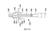
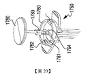
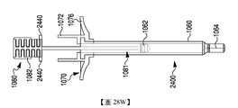
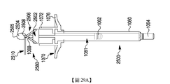
本文揭示了藥物遞送裝置。在本揭示案之一個實施例中,一種藥物遞送裝置包括:一主體;一柱塞桿,該柱塞桿部分地安置於該主體內部;一突起,該突起自該柱塞桿延伸;及在該主體上之一阻擋組件。當該突起相對於該阻擋組件處於一第一位置時,該阻擋組件限制該柱塞桿向遠側移動至一第一擋止點,且當該突起相對於該阻擋組件處於一第二位置時,該阻擋組件限制該柱塞桿向遠側移動至一第二擋止點。This article discloses a drug delivery device. In one embodiment of the present disclosure, a drug delivery device includes: a main body; a plunger rod partially disposed inside the main body; a protrusion extending from the plunger rod; and A blocking component on the main body. When the protrusion is in a first position relative to the blocking component, the blocking component restricts the plunger rod from moving distally to a first stopping point, and when the protrusion is in a second position relative to the blocking component , The blocking component restricts the plunger rod from moving distally to a second stop point.
在本揭示案之一些態樣中,該藥物遞送裝置進一步包括安置於該主體中之一擋止件。該柱塞桿向遠側移動使該擋止件向遠側移動,且一藥物物質安置於該主體中,在該擋止件與該主體之一遠端之間。該柱塞桿向遠側移動至該第一擋止點對該藥物遞送裝置進行灌注,且該柱塞桿向遠側移動至該第二擋止點自該裝置之一遠端分配一預定體積之該藥物物質。In some aspects of the present disclosure, the drug delivery device further includes a stopper disposed in the main body. The distal movement of the plunger rod causes the stopper to move distally, and a drug substance is arranged in the main body between the stopper and a distal end of the main body. The plunger rod moves distally to the first stop point to infuse the drug delivery device, and the plunger rod moves distally to the second stop point to dispense a predetermined volume from a distal end of the device The drug substance.
在本揭示案之一些態樣中,使該突起自該第一位置移動至該第二位置包括相對於該阻擋組件扭轉該柱塞桿。在本揭示案之一些態樣中,該藥物遞送裝置進一步包括在該阻擋組件之一近側面中的一空腔,該空腔經設定大小且經組態以收納該突起之一部分。當該突起相對於該阻擋組件處於該第二位置時,該突起位於該空腔近側,使得該柱塞桿向遠側移動使該突起移動至該空腔中。In some aspects of the present disclosure, moving the protrusion from the first position to the second position includes twisting the plunger rod relative to the blocking component. In some aspects of the present disclosure, the drug delivery device further includes a cavity in a proximal side of the blocking component, the cavity being sized and configured to receive a portion of the protrusion. When the protrusion is in the second position relative to the blocking component, the protrusion is located near the cavity, so that the plunger rod moves distally to move the protrusion into the cavity.
在本揭示案之一些態樣中,該空腔為一第一空腔,且該藥物遞送裝置進一步包括在該阻擋組件之一近側面中的一第二空腔,該第二空腔經設定大小且經組態以收納該突起之一部分。該第一空腔與該第二空腔位於該藥物遞送裝置之一中心縱軸線之相對側。在本揭示案之一些態樣中,該阻擋組件包括一凸緣且耦接至該主體之一近端部分,且該柱塞桿穿過該阻擋組件中之一開口。在本揭示案之一些態樣中,該藥物遞送裝置進一步包括在該柱塞桿之一近端部分處的一致動部分,且該突起自該致動部分延伸。In some aspects of the present disclosure, the cavity is a first cavity, and the drug delivery device further includes a second cavity in a proximal side of the blocking component, the second cavity being set It is sized and configured to accommodate a part of the protrusion. The first cavity and the second cavity are located on opposite sides of a central longitudinal axis of the drug delivery device. In some aspects of the present disclosure, the blocking component includes a flange and is coupled to a proximal portion of the main body, and the plunger rod passes through an opening in the blocking component. In some aspects of the present disclosure, the drug delivery device further includes an actuating portion at a proximal end portion of the plunger rod, and the protrusion extends from the actuating portion.
在本揭示案之一些態樣中,該致動部分包括一大體上圓柱形之形狀,該形狀具有比該柱塞桿之其餘部分之一寬度大的一直徑。該突起自該大體上圓柱形之形狀的一側延伸,且該致動部分進一步包括在該致動部分之一近端上的一拇指墊及在該大體上圓柱形之形狀之該側之一外表面上的一環。在本揭示案之一些態樣中,該藥物遞送裝置進一步包括在該阻擋組件上之一近側軸環,且該致動部分部分地配合於該近側軸環內部。In some aspects of the present disclosure, the actuating portion includes a substantially cylindrical shape having a diameter larger than a width of the rest of the plunger rod. The protrusion extends from one side of the generally cylindrical shape, and the actuating portion further includes a thumb pad on a proximal end of the actuating portion and one of the sides of the generally cylindrical shape A ring on the outer surface. In some aspects of the present disclosure, the drug delivery device further includes a proximal collar on the blocking component, and the actuation part is partially fitted inside the proximal collar.
在本揭示案之一些態樣中,該柱塞桿進一步包括自該致動部分向遠側突出之一對延伸部,且該阻擋組件包括一對開口。每一延伸部之一部分經組態以在該第一擋止點被該對開口中之一者收納。在本揭示案之一些態樣中,該阻擋組件包括沿著該阻擋組件之一底壁形成的一或多個凹口。每一延伸部之一部分經組態以在該柱塞桿相對於該阻擋組件向遠側移動時被該一或多個凹口收納,以允許該柱塞桿向遠側移動至該第二擋止點。In some aspects of the present disclosure, the plunger rod further includes a pair of extension portions protruding distally from the actuation portion, and the blocking component includes a pair of openings. A part of each extension is configured to be received by one of the pair of openings at the first stop point. In some aspects of the present disclosure, the blocking component includes one or more notches formed along a bottom wall of the blocking component. A portion of each extension is configured to be received by the one or more recesses when the plunger rod moves distally relative to the blocking assembly to allow the plunger rod to move distally to the second stop Stop point.
在本揭示案之一些態樣中,該阻擋組件包括沿著該阻擋組件之一側壁形成的一對內部凹槽。每一延伸部之一部分經組態以在該柱塞桿相對於該阻擋組件旋轉時被該對內部凹槽中之至少一者收納,以使該等延伸部自一壓縮狀態徑向向外展開為一鬆弛狀態。在本揭示案之一些態樣中,該突起為一第一突起,且該藥物遞送裝置進一步包括一第二突起,該第二突起自該柱塞桿沿著與該第一突起相反之一方向延伸。在本揭示案之一些態樣中,該阻擋組件可滑動地耦接至該主體且包括一對内部肋形物,該對内部肋形物經組態以在該主體可滑動地耦接至該阻擋組件時接合主體之一頂部凸緣。該對內部肋形物經組態以將一指向遠側之力施加於該頂部凸緣。In some aspects of the present disclosure, the blocking component includes a pair of internal grooves formed along a sidewall of the blocking component. A portion of each extension is configured to be received by at least one of the pair of internal grooves when the plunger rod rotates relative to the blocking assembly, so that the extensions expand radially outward from a compressed state It is a relaxed state. In some aspects of the present disclosure, the protrusion is a first protrusion, and the drug delivery device further includes a second protrusion from the plunger rod along a direction opposite to the first protrusion extend. In some aspects of the present disclosure, the blocking component is slidably coupled to the main body and includes a pair of internal ribs configured to be slidably coupled to the main body When blocking the assembly, engage one of the top flanges of the main body. The pair of internal ribs are configured to apply a distally directed force to the top flange.
在本揭示案之一些態樣中,該阻擋組件可滑動地耦接至該主體且包括一對可移動凸片,該對可移動凸片經組態以在該主體可滑動地耦接至該阻擋組件時接合該主體之一套管。該對可移動凸片在將該套管收納於該阻擋組件中時可側向地偏轉且經組態以將一徑向指向之力施加於該套管上。在本揭示案之一些態樣中,該阻擋組件進一步包括一對指凸緣。該等指凸緣中之每一者包括一有紋理之表面,該有紋理之表面具有一預定圖案,該預定圖案增大對該阻擋組件之一抓握。In some aspects of the present disclosure, the blocking component is slidably coupled to the main body and includes a pair of movable tabs configured to be slidably coupled to the main body When blocking the assembly, it engages with a sleeve of the main body. The pair of movable tabs can deflect laterally when the sleeve is received in the blocking assembly and are configured to apply a radially directed force on the sleeve. In some aspects of the present disclosure, the blocking component further includes a pair of finger flanges. Each of the finger flanges includes a textured surface with a predetermined pattern that increases the grip on one of the blocking components.
根據本揭示案之另一個實施例,一種藥物遞送裝置包括:一主體;一柱塞桿,該柱塞桿具有一遠端及一近端,該遠端耦接至該主體內部之一擋止件,該近端包括具有一拇指墊之一致動部分;複數個突起,該複數個突起自該致動部分延伸;及一阻擋組件,該阻擋組件安置於該主體上,該阻擋組件包括一近側軸環。當該等突起及該阻擋組件處於一第一組態時,該阻擋組件限制該柱塞桿向遠側移動至一第一擋止點,且當該等突起及該阻擋組件處於一第二組態時,該阻擋組件限制該柱塞桿向遠側移動至一第二擋止點。當該等突起處於該第二組態時,該近側軸環經組態以在該柱塞桿向遠側移動時收納該等突起。According to another embodiment of the present disclosure, a drug delivery device includes: a main body; a plunger rod having a distal end and a proximal end, the distal end being coupled to a stopper inside the main body The proximal end includes an actuating portion with a thumb pad; a plurality of protrusions extending from the actuating portion; and a blocking component disposed on the main body, the blocking component including a proximal Side shaft ring. When the protrusions and the blocking component are in a first configuration, the blocking component restricts the plunger rod from moving distally to a first stop point, and when the protrusions and the blocking component are in a second set In the state, the blocking component restricts the plunger rod from moving distally to a second stop point. When the protrusions are in the second configuration, the proximal collar is configured to receive the protrusions when the plunger rod moves distally.
在本揭示案之一些態樣中,該等突起及該阻擋組件可藉由該致動部分繞著一縱軸線相對於該阻擋組件旋轉而自該第一組態移動至該第二組態。在本揭示案之一些態樣中,該第一擋止點與該第二擋止點之間的一差距等於該擋止件為了自該主體之一遠端排出一預定體積之一藥物產品而必須行進的一距離。在本揭示案之一些態樣中,該複數個突起包括關於該致動部分對稱地安置之兩個突起。在本揭示案之一些態樣中,該阻擋組件進一步包括一對指凸緣。在本揭示案之一些態樣中,該藥物遞送裝置為一預填充式注射器。In some aspects of the present disclosure, the protrusions and the blocking component can be moved from the first configuration to the second configuration by rotating the actuating portion around a longitudinal axis relative to the blocking component. In some aspects of the present disclosure, a gap between the first stop point and the second stop point is equal to that the stopper is used to discharge a predetermined volume of a drug product from a distal end of the main body A distance that must be traveled. In some aspects of the present disclosure, the plurality of protrusions include two protrusions symmetrically arranged with respect to the actuating portion. In some aspects of the present disclosure, the blocking component further includes a pair of finger flanges. In some aspects of the present disclosure, the drug delivery device is a pre-filled syringe.
在本揭示案之一些態樣中,該藥物遞送裝置可:(a)藉由使該柱塞桿縱向地移動直至該柱塞桿到達該第一擋止點為止,自一使用前狀態變為一灌注狀態;(b)藉由使該柱塞桿相對於該阻擋組件旋轉直至該等突起及該阻擋組件處於該第二組態為止,自該灌注狀態變為一遞送狀態;且(c)藉由使該柱塞桿縱向地移動直至柱塞到達該第二擋止點為止,自一遞送狀態變為一已使用狀態。在本揭示案之一些態樣中,該柱塞桿包括安置於該致動部分遠側之一頸部,且該頸部與該阻擋組件中之一開口介接以防止該柱塞桿向近側移動。在本揭示案之一些態樣中,該頸部進一步與該阻擋組件中之該開口介接以防止該藥物遞送裝置自該遞送狀態移動至該灌注狀態。In some aspects of the present disclosure, the drug delivery device can: (a) by moving the plunger rod longitudinally until the plunger rod reaches the first stop point, it changes from a pre-use state to A perfusion state; (b) by rotating the plunger rod relative to the blocking component until the protrusions and the blocking component are in the second configuration, the perfusion state becomes a delivery state; and (c) By moving the plunger rod longitudinally until the plunger reaches the second stop point, it changes from a delivery state to a used state. In some aspects of the present disclosure, the plunger rod includes a neck disposed on the distal side of the actuating portion, and the neck is connected to an opening in the blocking component to prevent the plunger rod from approaching Move sideways. In some aspects of the present disclosure, the neck is further interfaced with the opening in the blocking component to prevent the drug delivery device from moving from the delivery state to the perfusion state.
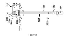
在本揭示案之另一個實施例中,一種藥物遞送裝置包括:一主體;一柱塞桿,該柱塞桿包括:一遠側部分,該遠側部分耦接至該主體內部之一擋止件;一近端,該近端包括安置於該主體外部的一大體上圓柱形之致動部分;及兩個突起,該等突起以一對稱組態自該致動部分之相對側延伸。該藥物遞送裝置進一步包括一阻擋組件,該阻擋組件耦接至該主體,該阻擋組件包括:一軸環,該軸環經組態以接納該致動部分之一遠側部分;及該軸環中之兩個空腔,該等空腔具有面向近側之開口。每一空腔經組態以接納該兩個突起中之一者的一遠側部分。該柱塞桿可縱向地移動且可繞著一縱軸線相對於該阻擋組件旋轉。當該藥物遞送裝置處於一使用前狀態時,該等突起與該等空腔開口未縱向地對準,且當該藥物遞送裝置處於一遞送狀態時,該等突起與該等空腔開口縱向地對準。在本揭示案之一些態樣中,該阻擋組件進一步包括一指凸緣,且該藥物遞送裝置進一步包括在該致動部分之一側上的一肋形表面。In another embodiment of the present disclosure, a drug delivery device includes: a main body; a plunger rod, the plunger rod includes: a distal portion coupled to a stopper inside the main body A proximal end, the proximal end includes a substantially cylindrical actuating portion disposed on the outside of the main body; and two protrusions, the protrusions extending from opposite sides of the actuating portion in a symmetrical configuration. The drug delivery device further includes a blocking component coupled to the main body, the blocking component including: a collar configured to receive a distal portion of the actuating portion; and in the collar The two cavities, the cavities have openings facing the proximal side. Each cavity is configured to receive a distal portion of one of the two protrusions. The plunger rod can move longitudinally and can rotate about a longitudinal axis relative to the blocking assembly. When the drug delivery device is in a pre-use state, the protrusions and the cavity openings are not longitudinally aligned, and when the drug delivery device is in a delivery state, the protrusions and the cavity openings are longitudinally aligned alignment. In some aspects of the present disclosure, the blocking component further includes a finger flange, and the drug delivery device further includes a ribbed surface on one side of the actuating portion.
在本揭示案之另一個實施例中,揭示了一種自具有一柱塞桿及一主體之一藥物輸送裝置分配一物質之方法。該方法包括:使該柱塞桿推進一預定距離而進入該主體中,直至該柱塞桿之推進受一擋塊抵制為止;使該柱塞桿繞著一縱軸線旋轉;及致動該柱塞桿以分配一預定體積之該物質。In another embodiment of the present disclosure, a method for dispensing a substance from a drug delivery device having a plunger rod and a main body is disclosed. The method includes: advancing the plunger rod a predetermined distance into the main body until the advancement of the plunger rod is resisted by a stop; rotating the plunger rod around a longitudinal axis; and actuating the column The plug rod dispenses a predetermined volume of the substance.
在本揭示案之一些態樣中,使該柱塞桿推進及致動該柱塞桿包括按壓該柱塞桿之一致動部分。在本揭示案之一些態樣中,該柱塞桿包括一突起,該擋塊包括耦接至該主體之一阻擋組件,且該阻擋組件鄰接該突起以抵制該柱塞桿之推進。In some aspects of the present disclosure, advancing the plunger rod and actuating the plunger rod include pressing the actuating portion of the plunger rod. In some aspects of the present disclosure, the plunger rod includes a protrusion, the stopper includes a blocking component coupled to the main body, and the blocking component is adjacent to the protrusion to resist the advancement of the plunger rod.
在本揭示案之一些態樣中,使該柱塞桿旋轉包括相對於該柱塞桿之一阻擋組件扭轉該柱塞桿之一致動部分,直至該柱塞桿上之一突起變成與該阻擋組件中之一空腔縱向地對準為止。在本揭示案之一些態樣中,致動該柱塞桿包括按壓該柱塞桿之該致動部分以使該突起推進至該空腔中。In some aspects of the present disclosure, rotating the plunger rod includes twisting the actuating portion of the plunger rod relative to a blocking component of the plunger rod until a protrusion on the plunger rod becomes in contact with the blocking component. One of the cavities in the assembly is aligned longitudinally. In some aspects of the present disclosure, actuating the plunger rod includes pressing the actuating portion of the plunger rod to advance the protrusion into the cavity.
在本揭示案之一些態樣中,該方法進一步包括使該突起推進至該空腔中,直至該突起鄰接該空腔之一遠側為止,且當該突起鄰接該空腔之該遠側時分配該預定體積之該物質。In some aspects of the present disclosure, the method further includes advancing the protrusion into the cavity until the protrusion abuts a distal side of the cavity, and when the protrusion abuts the distal side of the cavity Dispense the predetermined volume of the substance.
在本揭示案之另一個實施例中,一種藥物遞送裝置包括:一主體;一擋止件,該擋止件安置於該主體內部;及一套管,該套管具有一近端及一遠端。該遠端在該擋止件近側安置於該主體內部。該裝置包括至少部分地安置於該套管内部之一柱塞桿。當該擋止件處於一就緒位置時,(a)僅該套管、(b)僅該柱塞桿或(c)該套管與該柱塞桿兩者一起中之一者相對於該主體向遠側推進使該擋止件推進至一灌注位置。當該擋止件處於該灌注位置時,(a)僅該套管、(b)僅該柱塞桿或(c)該套管與該柱塞桿兩者一起中之另一者相對於該主體向遠側推進使該擋止件推進至一劑量完成位置。In another embodiment of the present disclosure, a drug delivery device includes: a main body; a stopper arranged inside the main body; and a sleeve tube having a proximal end and a distal end end. The distal end is arranged inside the main body on the proximal side of the stopper. The device includes a plunger rod at least partially disposed inside the casing. When the stopper is in a ready position, (a) only the sleeve, (b) only the plunger rod, or (c) the sleeve and the plunger rod are relative to the main body Pushing distally pushes the stopper to a perfusion position. When the stopper is in the filling position, (a) only the sleeve, (b) only the plunger rod, or (c) the other of the sleeve and the plunger rod relative to the The main body advances distally to advance the stopper to a dose completion position.
在本揭示案之一些態樣中,該藥物遞送裝置進一步包括一可移除阻擋組件,該可移除阻擋組件安置於該套管之一近側部分與該主體之一近端之間。該阻擋組件阻礙該套管相對於該主體向遠側推進。在移除該阻擋組件之後,該套管相對於該主體向遠側推進使該擋止件推進至該灌注位置。該阻擋組件為圍繞該套管之至少一部分可移除地固定之一夾子。In some aspects of the present disclosure, the drug delivery device further includes a removable blocking component disposed between a proximal portion of the sleeve and a proximal end of the main body. The blocking component prevents the sleeve from being advanced distally with respect to the main body. After removing the blocking assembly, the sleeve is advanced distally with respect to the main body to advance the stopper to the perfusion position. The blocking component is a clip that is removably fixed around at least a part of the sleeve.
在本揭示案之一些態樣中,該藥物遞送裝置進一步包括一可移除鎖定組件,該可移除鎖定組件將該柱塞桿耦接至該套管。該套管與該柱塞桿兩者一起相對於該主體向遠側移動使該擋止件推進至該灌注位置。在移除該鎖定組件之後,僅該柱塞桿相對於該主體向遠側推進使該擋止件推進至該劑量完成位置。在該劑量完成位置,該柱塞桿之一近端鄰接該套管之一遠端,使得防止該柱塞桿相對於該主體向遠側推進更遠。該可移除鎖定組件包括一銷、一凸片或一棒中之一者。In some aspects of the present disclosure, the drug delivery device further includes a removable locking component that couples the plunger rod to the sleeve. The sleeve and the plunger rod move distally relative to the main body to advance the stopper to the perfusion position. After the locking assembly is removed, only the plunger rod is advanced distally with respect to the main body to advance the stopper to the dose completion position. In the dose completion position, a proximal end of the plunger rod abuts a distal end of the sleeve, so that the plunger rod is prevented from being advanced distally with respect to the main body. The removable locking assembly includes one of a pin, a tab, or a rod.
在本揭示案之一些態樣中,該藥物遞送裝置進一步包括:一突起,該突起安置於該柱塞桿上;及一內突起,該內突起在該柱塞桿之該突起遠側安置於該套管之一內壁上。僅該柱塞桿相對於該主體向遠側推進使該擋止件推進至該灌注位置且致使該柱塞桿之該突起接觸該套管之該內突起。在該柱塞桿之該突起接觸該套管之該內突起之後,該柱塞桿與該套管兩者相對於該主體向遠側推進使該擋止件推進至該劑量完成位置。In some aspects of the present disclosure, the drug delivery device further includes: a protrusion disposed on the plunger rod; and an inner protrusion disposed on the distal side of the protrusion of the plunger rod On the inner wall of one of the sleeves. Only the plunger rod is advanced distally with respect to the main body to advance the stopper to the perfusion position and cause the protrusion of the plunger rod to contact the inner protrusion of the sleeve. After the protrusion of the plunger rod contacts the inner protrusion of the sleeve, both the plunger rod and the sleeve are advanced distally with respect to the main body to advance the stopper to the dose completion position.
在本揭示案之一些態樣中,在該柱塞桿上之一可壓縮突起,及在該柱塞桿上之該突起近側安置於該套管之一内壁上的一開口。僅該柱塞桿相對於該主體向遠側推進使該擋止件推進至該灌注位置。將該柱塞桿向近側抽出直至該該柱塞桿之該可壓縮突起進入該套管之該開口爲止將該套管耦接至該柱塞桿。耦接在一起之該柱塞桿與該套管兩者相對於該主體向遠側推進使該擋止件推進至該劑量完成位置。在本揭示案之一些態樣中,當該套管耦接至該柱塞桿時,該組合之套管及柱塞桿沿著一近側-遠側軸線之一總長度大於該柱塞桿獨自之一長度。In some aspects of the present disclosure, a compressible protrusion on the plunger rod, and an opening on an inner wall of the sleeve disposed proximally of the protrusion on the plunger rod. Only the plunger rod is advanced distally with respect to the main body to advance the stopper to the perfusion position. The plunger rod is drawn proximally until the compressible protrusion of the plunger rod enters the opening of the sleeve to couple the sleeve to the plunger rod. The plunger rod and the sleeve coupled together are advanced distally relative to the main body to advance the stopper to the dose completion position. In some aspects of the present disclosure, when the sleeve is coupled to the plunger rod, a total length of the combined sleeve and plunger rod along a proximal-distal axis is greater than the plunger rod One length alone.
在本揭示案之一些態樣中,該套管包括一指凸緣。在本揭示案之一些態樣中,該藥物遞送裝置進一步包括安置於該主體之一近端處的一擋塊。該擋塊經設定大小以在該擋止件處於該完成位置時即阻止該套管或該柱塞桿向遠側推進。In some aspects of the present disclosure, the sleeve includes a finger flange. In some aspects of the present disclosure, the drug delivery device further includes a stopper disposed at a proximal end of the main body. The size of the stopper is set to prevent the sleeve or the plunger rod from advancing distally when the stopper is in the completed position.
在本揭示案之其他實施例中,一種藥物遞送裝置包括:一主體;及一柱塞桿,該柱塞桿具有安置於該主體內部之一遠側部分及安置於該主體之一近端外部的一近側部分。該近側部分具有比該遠側部分之一寬度大的一寬度。該裝置進一步包括一障礙物,該障礙物在相對於該柱塞桿處於一阻礙位置時防止該柱塞桿自一灌注位置向遠側推進至一劑量完成位置。該障礙物自該阻礙位置移位准許該柱塞桿向遠側推進至該劑量完成位置。In other embodiments of the present disclosure, a drug delivery device includes: a main body; and a plunger rod having a distal portion disposed inside the main body and a proximal end disposed outside the main body Of a proximal part. The proximal portion has a width larger than a width of the distal portion. The device further includes an obstacle that prevents the plunger rod from advancing distally from an infusion position to a dose completion position when in an obstructed position relative to the plunger rod. The displacement of the obstacle from the blocking position permits the plunger rod to be advanced distally to the dose completion position.
在本揭示案之一些態樣中,該藥物遞送裝置進一步包括附著至該主體之一近端部分的一軸環。該軸環環繞該柱塞桿之該近側部分。該藥物遞送裝置進一步包括自該軸環徑向向內延伸之一軸環凸出部。該柱塞桿之該近側部分包括一通道,該軸環凸出部突出至該通道中,該通道包括一周向路徑及一軸向劑量完成路徑。該障礙物包括該軸環凸出部,該軸環凸出部在安置於該通道之該周向路徑中時防止該柱塞桿向遠側推進至該劑量完成位置。該障礙物自該阻礙位置移位包括將該柱塞桿繞著一縱軸線扭轉以使該軸環凸出部與該軸向劑量完成路徑對準。In some aspects of the present disclosure, the drug delivery device further includes a collar attached to a proximal portion of the main body. The collar surrounds the proximal portion of the plunger rod. The drug delivery device further includes a collar protrusion extending radially inward from the collar. The proximal part of the plunger rod includes a channel, the collar protrusion protrudes into the channel, and the channel includes a circumferential path and an axial dose completion path. The obstacle includes the collar protrusion that prevents the plunger rod from being advanced distally to the dose completion position when placed in the circumferential path of the channel. Displacement of the obstacle from the obstructing position includes twisting the plunger rod about a longitudinal axis to align the collar protrusion with the axial dose completion path.
在本揭示案之一些態樣中,該通道進一步包括一軸向灌注路徑,該軸向灌注路徑偏離該軸向劑量完成路徑且藉由該周向路徑連接至該軸向劑量完成路徑。該柱塞桿向遠側移動使得該軸環凸出部在該軸向灌注路徑上行進使該柱塞桿推進至該灌注位置。在本揭示案之一些態樣中,該軸環進一步包括一指凸緣。In some aspects of the present disclosure, the channel further includes an axial perfusion path that deviates from the axial dose completion path and is connected to the axial dose completion path by the circumferential path. Distal movement of the plunger rod causes the collar protrusion to travel on the axial irrigation path to advance the plunger rod to the irrigation position. In some aspects of the present disclosure, the collar further includes a finger flange.
在本揭示案之一些態樣中,該柱塞桿之該近側部分包括徑向向外延伸之一凸出部。該藥物遞送裝置進一步包括一可旋轉對準組件,該可旋轉對準組件安置於該柱塞桿之該近側部分與該主體之間。該對準組件包括一通道,該通道經設定大小且經組態以容納該柱塞桿凸出部。該障礙物包括該通道之一壁,在該柱塞桿處於該灌注位置時,該壁阻斷該柱塞桿凸出部之一遠側軸向路徑。該障礙物自該阻礙位置移位包括使該對準組件旋轉以自該柱塞桿凸出部之該遠側軸向路徑移除該通道之該壁。In some aspects of the present disclosure, the proximal portion of the plunger rod includes a protrusion extending radially outward. The drug delivery device further includes a rotatable alignment component that is disposed between the proximal portion of the plunger rod and the main body. The alignment assembly includes a channel that is sized and configured to accommodate the plunger rod protrusion. The obstacle includes a wall of the channel, and when the plunger rod is in the perfusion position, the wall blocks a distal axial path of the protrusion of the plunger rod. Displacement of the obstacle from the obstructing position includes rotating the alignment assembly to remove the wall of the channel from the distal axial path of the plunger rod protrusion.
在本揭示案之一些態樣中,該藥物遞送裝置進一步包括耦接至該主體之一近端部分的一指凸緣。該可旋轉對準組件安置於該指凸緣與該柱塞桿之該近側部分之間。在本揭示案之一些態樣中,該藥物遞送裝置進一步包括安置於該主體之該近端處的一凸緣片。該障礙物包括一可移除罩,在相對於該柱塞桿處於該阻礙位置時,該可移除罩部分地安置於該柱塞桿之該近側部分與該凸緣片之間。在本揭示案之一些態樣中,移除該罩允許該柱塞桿之該近側部分推進至一劑量完成位置。在該劑量完成位置,該柱塞桿之該近側部分接觸該凸緣片。在本揭示案之一些態樣中,在處於該阻礙位置時,該可移除罩遮蓋該柱塞桿之該近側部分。In some aspects of the present disclosure, the drug delivery device further includes a finger flange coupled to a proximal portion of the main body. The rotatable alignment component is disposed between the finger flange and the proximal portion of the plunger rod. In some aspects of the present disclosure, the drug delivery device further includes a flange sheet disposed at the proximal end of the main body. The obstacle includes a removable cover, and when in the obstructing position relative to the plunger rod, the removable cover is partially disposed between the proximal portion of the plunger rod and the flange piece. In some aspects of the present disclosure, removing the cover allows the proximal portion of the plunger rod to advance to a dose completion position. In the dose completion position, the proximal portion of the plunger rod contacts the flange piece. In some aspects of the present disclosure, the removable cover covers the proximal portion of the plunger rod when in the obstructing position.
在本揭示案之一些態樣中,藥物遞送裝置進一步包括一軸環,該軸環安置於該主體之該近端與該柱塞桿之該近側部分之間。該軸環界定一開口,該開口經設定大小以在該柱塞桿向遠側推進超過一灌注位置時容納該柱塞桿之該近側部分。該障礙物包括一凸片,該凸片自該柱塞桿之該近側部分徑向向外突出,該凸片防止該柱塞桿之該近側部分配合至該軸環之該開口中。該軸環開口之一深度與該柱塞桿為了向遠側推進至該劑量完成位置而必須行進之一距離一致。In some aspects of the present disclosure, the drug delivery device further includes a collar disposed between the proximal end of the main body and the proximal portion of the plunger rod. The collar defines an opening that is sized to accommodate the proximal portion of the plunger rod when the plunger rod is advanced distally beyond a perfusion position. The obstacle includes a protrusion that protrudes radially outward from the proximal portion of the plunger rod, and the protrusion prevents the proximal portion of the plunger rod from fitting into the opening of the collar. A depth of the collar opening coincides with a distance that the plunger rod must travel in order to advance distally to the dose completion position.
在本揭示案之一些態樣中,該障礙物自該阻礙位置移位包括移除該凸片或將該凸片壓縮至該柱塞桿之該近側部分之一側中。在本揭示案之一些態樣中,該凸片為一第一凸片,且其中該障礙物進一步包括一第二凸片,該第二凸片自該柱塞桿之該近側部分沿著與該第一凸片之突出方向相反的一方向徑向向外突出。在本揭示案之一些態樣中,該障礙物包括一凸片,在處於該阻礙位置時,該凸片安置於該主體與該柱塞桿之該近側部分之間。該柱塞桿包括安置於該凸片近側之一幾何形狀,且當該凸片處於該阻礙位置時,該幾何形狀無法向遠側推進越過該凸片。In some aspects of the present disclosure, the displacement of the obstacle from the obstructing position includes removing the tab or compressing the tab into one side of the proximal portion of the plunger rod. In some aspects of the present disclosure, the protruding piece is a first protruding piece, and wherein the obstacle further includes a second protruding piece, the second protruding piece runs along the proximal portion of the plunger rod A direction opposite to the protruding direction of the first tab protrudes radially outward. In some aspects of the present disclosure, the obstacle includes a protruding piece, and when in the obstructing position, the protruding piece is disposed between the main body and the proximal portion of the plunger rod. The plunger rod includes a geometric shape disposed on the proximal side of the tab, and when the tab is in the obstructing position, the geometric shape cannot be pushed distally past the tab.
在本揭示案之一些態樣中,該障礙物之移位包括藉由拉動該凸片將該凸片自該藥物遞送裝置移除。在本揭示案之一些態樣中,該藥物遞送裝置進一步包括一凸緣片,其中該凸片之一部分安置於該凸緣片之一空腔內部。在本揭示案之一些態樣中,該障礙物之移位包括藉由使該凸片斷裂而將該凸片自該藥物遞送裝置移除。In some aspects of the present disclosure, the displacement of the obstacle includes removing the tab from the drug delivery device by pulling the tab. In some aspects of the present disclosure, the drug delivery device further includes a flange piece, wherein a portion of the flange piece is disposed inside a cavity of the flange piece. In some aspects of the present disclosure, the displacement of the obstacle includes removing the tab from the drug delivery device by breaking the tab.
在本揭示案之一些態樣中,該障礙物包括一凸緣片,在處於該阻礙位置時,該凸緣片安置於該主體之該近端近側在該柱塞桿之該近側部分與該主體之間,且藉由一可移除之阻擋組件而與該主體之該近端間隔開。該障礙物自該阻礙位置之移位包括移除該阻擋組件及使該凸緣片朝向該主體之該近端向遠側偏移。In some aspects of the present disclosure, the obstacle includes a flange piece, and when in the obstructing position, the flange piece is disposed on the proximal side of the proximal end of the main body at the proximal portion of the plunger rod Between the main body and the proximal end of the main body by a removable blocking component. The displacement of the obstacle from the obstructing position includes removing the blocking component and shifting the flange to the distal side toward the proximal end of the main body.
在本揭示案之一些態樣中,該柱塞桿包括徑向向外延伸之一凸出部。該障礙物包括具有一末端之一桿子,在該阻礙位置,該桿子位於該凸出部遠側且阻止該凸出部向遠側移動且藉此阻止該柱塞桿向遠側移動。該障礙物自該阻礙位置移位包括致動該桿子以自其在該凸出部遠側之位置移除該桿子之該末端。在本揭示案之一些態樣中,該柱塞桿向遠側推進超過該劑量完成位置係藉由該柱塞桿之該近側部分與耦接至該主體之一凸緣片之一部分之間的接觸來防止。In some aspects of the present disclosure, the plunger rod includes a protrusion extending radially outward. The obstacle includes a rod having an end. In the obstructing position, the rod is located at the distal side of the protrusion and prevents the protrusion from moving distally and thereby prevents the plunger rod from moving distally. Displacement of the obstacle from the obstructing position includes actuating the rod to remove the end of the rod from its position distal to the protrusion. In some aspects of the present disclosure, the plunger rod is advanced distally beyond the dose completion position by between the proximal portion of the plunger rod and a portion of a flange coupled to the main body Contact to prevent.
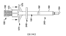
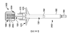
在本揭示案之其他實施例中,一種藥物遞送裝包括一主體及附著至該主體之一套管。該套管包括一近端、一遠端及一開口,該開口安置於該套管之一周向壁中。該藥物遞送裝置進一步包括穿過該套管之一柱塞桿,該柱塞桿包括安置於該主體內部之一遠端部分及一徑向延伸之突起。該柱塞桿可自一就緒位置至一灌注位置向遠側推進至該主體中。在該灌注位置,該柱塞桿之該突起安置於該開口内部,且該柱塞桿之向遠側進一步推進受該突起與該開口之一壁之間的接觸抵制。可對該突起施加壓力以克服該柱塞桿向遠側進一步推進之阻力。In other embodiments of the present disclosure, a drug delivery device includes a main body and a sleeve attached to the main body. The sleeve includes a proximal end, a distal end and an opening, and the opening is arranged in a circumferential wall of the sleeve. The drug delivery device further includes a plunger rod passing through the sleeve, the plunger rod including a distal portion disposed inside the main body and a radially extending protrusion. The plunger rod can be advanced distally into the main body from a ready position to an infusion position. In the filling position, the protrusion of the plunger rod is disposed inside the opening, and the further advancement of the plunger rod is resisted by the contact between the protrusion and a wall of the opening. Pressure can be applied to the protrusion to overcome the resistance of the plunger rod to further advance distally.
在本揭示案之一些態樣中,該套管中之該開口為一第二開口,且該套管進一步包括在該第二開口近側安置於該套管之該周向壁中的一第一開口及在該第二開口遠側安置於該套管之該周向壁中的一第三開口。在該就緒位置,該柱塞桿之該突起安置於該第一開口中,且該柱塞桿向遠側進一步推進藉由該突起與該第一開口之一壁之間的接觸抵制。在該柱塞桿向遠側進一步推進越過該灌注位置之後,該柱塞桿之該突起安置於該第三開口中,且防止該柱塞桿向遠側進一步推進。In some aspects of the present disclosure, the opening in the sleeve is a second opening, and the sleeve further includes a first opening disposed in the circumferential wall of the sleeve near the second opening And a third opening arranged in the circumferential wall of the sleeve at the distal side of the second opening. In the ready position, the protrusion of the plunger rod is disposed in the first opening, and the plunger rod is further advanced distally to be resisted by the contact between the protrusion and a wall of the first opening. After the plunger rod is further advanced distally past the filling position, the protrusion of the plunger rod is disposed in the third opening, and the plunger rod is prevented from being further advanced distally.
在本揭示案之一些態樣中,該沿徑向延伸之突起為一第一突起,且該柱塞桿進一步包括一第二沿徑向延伸之突起,該第二沿徑向延伸突起與該第一突起相對。在沿遠側方向對該柱塞桿施加軸向壓力時將該第一突起及該第二突起朝向彼此擠壓克服了該柱塞桿向遠側進一步推進之阻力。在本揭示案之一些態樣中,該套管之一近端包括一張開之開口。使該柱塞桿自該就緒位置向遠側推進至該灌注位置包括使該突起推進至該張開之開口中且穿過該套管,藉此該突起被壓縮於該套管之内部與該柱塞桿之間,直至該突起延伸至安置於該套管之該周向壁中的開口中。在本揭示案之一些態樣中,該突起包括有助於該柱塞桿向遠側推進的一向遠側漸縮之輪廓。In some aspects of the present disclosure, the radially extending protrusion is a first protrusion, and the plunger rod further includes a second radially extending protrusion, the second radially extending protrusion and the The first protrusion is opposite. When axial pressure is applied to the plunger rod in the distal direction, pressing the first protrusion and the second protrusion toward each other overcomes the resistance of the plunger rod to further advance distally. In some aspects of the present disclosure, a proximal end of the sleeve includes an open opening. Advancing the plunger rod distally from the ready position to the perfusion position includes advancing the protrusion into the open opening and through the sleeve, whereby the protrusion is compressed inside the sleeve and the plunger Between the rods until the protrusion extends into the opening disposed in the circumferential wall of the sleeve. In some aspects of the present disclosure, the protrusion includes a distally tapered profile that helps the plunger rod to advance distally.
在本揭示案之其他實施例中,一種藥物遞送裝置包括:一主體;一柱塞桿,該柱塞桿包括安置於該主體內部之一遠端部分及一可旋轉元件;及一套管,該套管附著至該主體,該套管包括一近側開口,該柱塞桿可推進至該近側開口中。使該可旋轉元件旋轉致使該柱塞桿向遠側推進至一灌注位置。一旦該柱塞桿處於該灌注位置,便抵制該可旋轉元件之進一步旋轉。In other embodiments of the present disclosure, a drug delivery device includes: a main body; a plunger rod including a distal end portion and a rotatable element disposed inside the main body; and a sleeve, The sleeve is attached to the main body, the sleeve includes a proximal opening into which the plunger rod can be advanced. Rotating the rotatable element causes the plunger rod to advance distally to a perfusion position. Once the plunger rod is in the filling position, further rotation of the rotatable element is resisted.
在本揭示案之一些態樣中,該可旋轉元件包括一凸輪桿。一旦該柱塞桿處於該灌注位置,便可將該柱塞桿壓低至該主體中以使該柱塞桿向遠側推進至一劑量完成位置。在本揭示案之一些態樣中,該藥物遞送裝置進一步包括一軸環,該軸環安置於該主體之一近端處,該軸環之一內部包括形成一近側螺旋形路徑之一近側螺紋部分。該可旋轉元件包括該柱塞桿之一近側部分,該近側部分包括一突起。該柱塞桿之該近端部分可繞著縱軸線旋轉,以致使該突起沿著該近側螺旋形路徑向遠側行進。一旦該突起到達該軸環之近側螺紋部分之端部,該柱塞桿即處於該灌注位置。In some aspects of the present disclosure, the rotatable element includes a cam lever. Once the plunger rod is in the perfusion position, the plunger rod can be depressed into the main body to advance the plunger rod distally to a dose completion position. In some aspects of the present disclosure, the drug delivery device further includes a collar disposed at a proximal end of the main body, and an inside of the collar includes a proximal side forming a proximal spiral path Threaded part. The rotatable element includes a proximal portion of the plunger rod, the proximal portion including a protrusion. The proximal portion of the plunger rod can rotate about the longitudinal axis, so that the protrusion travels distally along the proximal spiral path. Once the protrusion reaches the end of the proximal threaded portion of the collar, the plunger rod is in the filling position.
在本揭示案之一些態樣中,一旦該柱塞桿處於該灌注位置,便可將該柱塞桿沿軸向壓低至該主體中以使該柱塞桿向遠側推進至一劑量完成位置。在本揭示案之一些態樣中,該軸環之内部進一步包括一遠側螺紋部分。該遠側螺紋部分之螺紋形成偏離該近側螺旋形路徑且與該近側螺旋形路徑相對的一遠側螺旋形路徑。該突起與該遠側螺旋形路徑之對準將該柱塞桿置於該灌注位置。該柱塞桿之該近側部分旋轉以致使該突起沿著該遠側螺旋形路徑向遠側行進致使該柱塞桿向遠側推進至一劑量完成位置。In some aspects of the present disclosure, once the plunger rod is in the perfusion position, the plunger rod can be axially depressed into the main body to advance the plunger rod distally to a dose completion position . In some aspects of the present disclosure, the interior of the collar further includes a distal threaded portion. The thread of the distal thread portion forms a distal spiral path that deviates from the proximal spiral path and is opposite to the proximal spiral path. The alignment of the protrusion with the distal spiral path places the plunger rod in the perfusion position. The proximal portion of the plunger rod rotates to cause the protrusion to travel distally along the distal spiral path causing the plunger rod to advance distally to a dose completion position.
在本揭示案之其他實施例中,一種藥物遞送裝置包括:一主體;一擋止件,該擋止件安置於該主體内部;及一第一柱塞桿,該第一柱塞桿具有一第一近端部分及比該第一近端部分窄之一第一遠端部分。該第一遠端部分具有一第一長度。該藥物遞送裝置進一步包括一第二柱塞桿,該第二柱塞桿具有一第二近端部分及比該近端部分窄之一第二遠端部分。該第二遠端部分具有一第二長度。該藥物遞送裝置進一步包括附著至該主體之一近端部分的一指凸緣。該指凸緣具有與該主體之一近側開口對準的一通孔。該通孔經設定大小以容納該第一遠端部分及該第二遠端部分中之每一者而不容納該第一近端部分或該第二近端部分中之任一者。該第一遠端部分推進穿過該通孔直至該第一近端部分鄰接該指凸緣將該擋止件向遠側推動至一灌注位置。該第二遠端部分推進穿過該通孔直至該第二近端部分鄰接該指凸緣將該擋止件向遠側推動至一劑量完成位置。In other embodiments of the present disclosure, a drug delivery device includes: a main body; a stopper disposed inside the main body; and a first plunger rod, the first plunger rod has a A first proximal portion and a first distal portion narrower than the first proximal portion. The first distal portion has a first length. The drug delivery device further includes a second plunger rod having a second proximal portion and a second distal portion narrower than the proximal portion. The second distal portion has a second length. The drug delivery device further includes a finger flange attached to a proximal portion of the main body. The finger flange has a through hole aligned with a proximal opening of the main body. The through hole is sized to accommodate each of the first distal portion and the second distal portion but does not accommodate either the first proximal portion or the second proximal portion. The first distal end portion advances through the through hole until the first proximal end portion abuts the finger flange and pushes the stopper distally to a perfusion position. The second distal end portion advances through the through hole until the second proximal end portion abuts the finger flange and pushes the stopper distally to a dose completion position.
在本揭示案之其他實施例中,一種組裝藥物遞送裝置之方法包括:將一主體耦接至一阻擋組件,其中該阻擋組件為一凸緣片;及將一柱塞桿耦接至該阻擋組件,使得在一預組裝狀態下,該柱塞桿部分地安置於該主體內部且抑制該柱塞桿相對於該阻擋組件向近側移動。在該預組裝狀態下,該柱塞桿經組態以相對於該阻擋組件向遠側移動至一第一擋止點,其中該柱塞桿之一突起接合該阻擋組件,藉此致使一藥劑之一灌注劑量自該主體排出。當該突起接合至該阻擋組件時,該阻擋組件經組態以限制該柱塞桿向遠側移動至一第一擋止點。該柱塞桿經進一步組態以在該柱塞桿處於該第一擋止點時相對於該阻擋組件旋轉以使該突起與該阻擋組件分離,且相對於該阻擋組件向遠側移動至一第二擋止點,其中該突起接合該阻擋組件,藉此致使一藥劑之一遞送劑量自該主體排出。In other embodiments of the present disclosure, a method of assembling a drug delivery device includes: coupling a body to a blocking component, wherein the blocking component is a flange piece; and coupling a plunger rod to the blocking component The assembly is such that in a pre-assembled state, the plunger rod is partially disposed inside the main body and restrains the plunger rod from moving proximally relative to the blocking assembly. In the pre-assembled state, the plunger rod is configured to move distally relative to the blocking component to a first stopping point, wherein a protrusion of the plunger rod engages the blocking component, thereby causing a medicine One of the perfusion doses is expelled from the body. When the protrusion is coupled to the blocking component, the blocking component is configured to restrict the plunger rod from moving distally to a first stop point. The plunger rod is further configured to rotate relative to the blocking component when the plunger rod is at the first stop point to separate the protrusion from the blocking component, and to move distally relative to the blocking component to a position The second stop point, wherein the protrusion engages the blocking component, thereby causing a delivered dose of a medicament to be discharged from the main body.
在本揭示案之一些態樣中,該方法進一步包括將該主體之一頂部凸緣插入於該阻擋組件之一開口中,致使該阻擋組件之一凸片徑向向外地偏轉且致使該阻擋組件之一肋形物向近側偏轉。該凸片將一徑向向內地指向之力施加於該主體,且該肋形物將一遠側力施加於該頂部凸緣,以將該主體固定至該阻擋組件。該方法進一步包括在該預組裝狀態下將該柱塞桿之一延伸部插入於該阻擋組件之一側部開口中以將該柱塞桿附接至該阻擋組件。該柱塞桿經組態以回應於使該柱塞桿相對於該阻擋組件向遠側移動至該第一擋止點而使該延伸部徑向向內偏轉,使得自該側部開口移除該延伸部。該延伸部經組態以在該柱塞桿相對於該阻擋組件旋轉時對接該阻擋組件之一內部移動以使該突起與該阻擋組件之一狹槽對準。在該突起與該狹槽對準時,該延伸部在該阻擋組件內徑向向外撓曲。該延伸部經組態以在該柱塞桿向遠側移動至該第二擋止點時沿著該阻擋組件之內部延伸至一凹口中。In some aspects of the present disclosure, the method further includes inserting a top flange of the main body into an opening of the blocking component, causing a tab of the blocking component to deflect radially outward and causing the blocking component One of the ribs deflects proximally. The tab applies a radially inwardly directed force to the main body, and the rib applies a distal force to the top flange to fix the main body to the blocking component. The method further includes inserting an extension of the plunger rod into a side opening of the blocking assembly in the pre-assembled state to attach the plunger rod to the blocking assembly. The plunger rod is configured to deflect the extension radially inwardly in response to moving the plunger rod distally with respect to the blocking assembly to the first stop point so as to be removed from the side opening The extension. The extension is configured to abut the inside of one of the blocking components to move when the plunger rod rotates relative to the blocking component to align the protrusion with a slot of the blocking component. When the protrusion is aligned with the slot, the extension flexes radially outward within the blocking assembly. The extension part is configured to extend into a recess along the inside of the blocking component when the plunger rod moves distally to the second stop point.
相關申請案之交互參照Cross-reference of related applications
本申請案主張以下各案之優先權:於2019年6月5日申請之美國臨時申請案No. 62/857,678;及於2019年6月12日申請之美國臨時申請案No. 62/860,481;以上各案以引用方式整體併入本文中。This application claims the priority of the following cases: U.S. Provisional Application No. 62/857,678 filed on June 5, 2019; and U.S. Provisional Application No. 62/860,481 filed on June 12, 2019; The above cases are incorporated into this article in their entirety by reference.
除了於2018年12月12日申請之國際申請案No.PCT/US2018/065192之態樣之外,亦可使用本揭示案之實施例,及/或將本揭示案之實施例與國際申請案No.PCT/US2018/065192之態樣結合使用,該申請案以引用方式整體併入本文中。In addition to the aspect of International Application No. PCT/US2018/065192 filed on December 12, 2018, the embodiments of this disclosure can also be used, and/or the embodiments of this disclosure can be combined with the international application No. PCT/US2018/065192 is used in combination, and the application is incorporated herein by reference in its entirety.
如本文中所使用,術語「包括」、「包括了」、「包含」、「包含了」或其任何其他變型旨在覆蓋非排他性之包括,使得包括一系列元件之過程、方法、物品或設備不僅僅包括彼等元件,而是可包括未明確列出或此類過程、方法、物品或設備所固有之其他元件。術語「示例性」係按「實例」而非「理想的」之意義使用。明顯地,本文中被描述為「實例」或「示例性」之實施例或實現方式不應被理解為例如比其他實施例或實現方式較佳或有利;而是,其意欲反映或指示該(等)實施例為一个「實例」而非「理想的」。另外,術語「第一」、「第二」等在本文中不表示任何順序、數量或重要性,而是用於將元件、結構、步驟或過程彼此區分開。此外,術語「一個」及「一種」在本文中不表示數量限制,而是表示存在一或多個所提及之項目。另外,除非另外說明,否則術語「約」、「大約」、「實質上」等在用於描述數值時表示該值之+/-10%的變化。As used herein, the terms "include", "includes", "includes", "includes" or any other variants thereof are intended to cover non-exclusive inclusion, so that a process, method, article or device that includes a series of elements It does not only include these elements, but may include other elements that are not explicitly listed or are inherent to such processes, methods, articles, or equipment. The term "exemplary" is used in the sense of "example" rather than "ideal". Obviously, the embodiments or implementations described herein as "examples" or "exemplary" should not be construed as, for example, better or advantageous than other embodiments or implementations; rather, they are intended to reflect or indicate the ( Etc.) The embodiment is an "example" rather than an "ideal". In addition, the terms "first", "second", etc. do not denote any order, quantity, or importance herein, but are used to distinguish elements, structures, steps, or processes from each other. In addition, the terms "one" and "one" in this article do not indicate a quantitative limit, but rather indicate that there are one or more of the mentioned items. In addition, unless otherwise specified, the terms "about", "approximately", "substantially", etc., when used to describe a value, represent a variation of +/-10% of the value.
本揭示案之實施例可與任何類型之含流體產品一起使用,諸如液體藥物物質、液體安慰劑或可以劑型分配之其他液體。如本文所用,術語「藥物物質」可指包含一種或多種活性成分(諸如,例如,小分子或大分子)之配製物質,諸如止痛藥、類固醇或生物製劑。如本文中所使用,術語「生物的」可指在諸如細胞之活體系統中產生的大分子(例如,具有大於15 kDa、大於30 kDa、大於50 kDa、大於75 kDa或大於100 kDa之大小)。生物製劑可包括蛋白質(例如抗體)、核酸、大糖(large sugar)等。與可具有明確定義之化學結構之小分子不同,生物製劑可具有無法藉由實驗室方法輕鬆量化的高度複雜之結構。如本文中所使用,術語「藥物產品」可指分配至主要包裝組件中以用於包裝、運輸、遞送及/或施用於患者的一定體積之藥物物質。The embodiments of the present disclosure can be used with any type of fluid-containing products, such as liquid drug substances, liquid placebos, or other liquids that can be dispensed in dosage form. As used herein, the term "drug substance" may refer to a formulation substance containing one or more active ingredients (such as, for example, small or macromolecules), such as analgesics, steroids, or biological agents. As used herein, the term "biological" can refer to a macromolecule produced in a living system such as a cell (e.g., having a size greater than 15 kDa, greater than 30 kDa, greater than 50 kDa, greater than 75 kDa, or greater than 100 kDa) . Biological agents may include proteins (such as antibodies), nucleic acids, large sugars, and the like. Unlike small molecules, which can have a well-defined chemical structure, biological agents can have highly complex structures that cannot be easily quantified by laboratory methods. As used herein, the term "drug product" may refer to a volume of a drug substance that is distributed into a main packaging component for packaging, transportation, delivery, and/or administration to a patient.
術語「主要包裝組件」係指用於藥物產品之包裝組件,諸如藥物容器,該包裝組件被設計及製造為與配製藥物物質直接實體接觸。(例如,參見《用於包裝人類藥物及生物製劑之容器封閉系統的行業指南》,美國衛生與人類服務部,食品及藥物管理局,藥物評估與研究中心及生物製劑評估與研究中心(1999年5月),該文章以引用方式併入本文中)。主要包裝組件之實例包括由玻璃、塑膠、其他聚合物或共聚物及/或其他材料製成之可預填充注射器、魯爾注射器、藥筒及小瓶。The term "primary packaging component" refers to a packaging component used for a pharmaceutical product, such as a drug container, which is designed and manufactured to be in direct physical contact with the formulated drug substance. (For example, see "Industry Guidelines for Container Closure Systems for Packaging Human Drugs and Biological Agents", U.S. Department of Health and Human Services, Food and Drug Administration, Center for Drug Evaluation and Research, and Center for Biologics Evaluation and Research (1999 May), the article is incorporated into this article by reference). Examples of major packaging components include pre-fillable syringes, Luer syringes, cartridges, and vials made of glass, plastic, other polymers or copolymers, and/or other materials.
如本文所使用,術語「遠側」及「向遠側」係指相對較接近於患者遞送位點或在該患者遞送位點之方向上的位置(或裝置之一部分),且術語「近側」及「向近側」係指相對較接近於與裝置之遠側位置/部分相對之使用者端或在該使用者端之方向上的位置(或裝置之部分)。As used herein, the terms "distal" and "distal" refer to a location (or part of the device) relatively close to or in the direction of the patient's delivery site, and the term "proximal" "" and "proximal" refer to the position (or part of the device) relatively close to the user end opposite to the distal position/part of the device or in the direction of the user end.
如本文所使用,術語「主體」在用於提及裝置之一部分時可指該裝置的適合於容納一定體積之藥物物質的組件。主體可包括,例如,筒(諸如注射器筒)、管、圓筒或裝置之其他容納部分。在一些實施例中,主體亦可包括一遠端部分,該遠端部分具有噴嘴、針、針附接位點及/或遠端罩。As used herein, the term "body" when used to refer to a part of a device can refer to a component of the device that is suitable for holding a volume of drug substance. The main body may include, for example, a barrel (such as a syringe barrel), a tube, a cylinder, or other containing parts of the device. In some embodiments, the main body may also include a distal portion having a nozzle, needle, needle attachment site, and/or distal cover.
本揭示案之實施例可與通常具有小劑量體積之產品(諸如,例如,眼科藥物產品)一起使用。在一些實施例中,本揭示案之裝置可與包括大分子(例如30 kDA或更大之分子量)之藥物產品一起使用。在一些實施例中,本揭示案之裝置可與包括大分子之片段的藥物產品一起使用。例如,在一些實施例中,本揭示案之裝置可與包括抗原結合分子之藥物產品一起使用。在一些態樣中,抗原結合分子可為抗體或抗原結合片段。在一些實施例中,本揭示案之裝置可適合於與某些藥物產品一起使用,該等藥物產品包括多種成分,諸如,例如,阿柏西普、阿利庫單抗、阿比西帕培高樂、貝伐珠單抗、布魯羅希單抗、康柏西普、度匹魯單抗、依洛尤單抗、托珠單抗、賽妥珠單抗、阿巴西普、利妥昔單抗、英夫利昔單抗、蘭尼單抗、賽利路單抗、阿達木單抗,阿那白滯素、曲妥珠單抗、培非格拉斯汀、幹擾素β-1a、甘精胰島素[rDNA來源]、依泊汀α、達貝泊汀、非力格蘭斯汀、戈利木單抗、依那西普、上述任何一者之抗原結合片段、或此類結合區之組合,諸如針對VEGF或血管生成素-2之雙特異性抗體等。The embodiments of the present disclosure can be used with products that generally have small dosage volumes, such as, for example, ophthalmic drug products. In some embodiments, the device of the present disclosure can be used with pharmaceutical products that include macromolecules (for example, a molecular weight of 30 kDA or greater). In some embodiments, the devices of the present disclosure can be used with pharmaceutical products that include fragments of macromolecules. For example, in some embodiments, the devices of the present disclosure can be used with pharmaceutical products that include antigen-binding molecules. In some aspects, the antigen-binding molecule may be an antibody or an antigen-binding fragment. In some embodiments, the device of the present disclosure may be suitable for use with certain pharmaceutical products that include multiple ingredients, such as, for example, aflibercept, alikuzumab, and abisipapercol. Le, Bevacizumab, Bruroximab, Conbercept, Dupiluzumab, Iloiuumab, Tocilizumab, Certuzumab, Abatacept, Rituxan Mab, infliximab, ranibizumab, celiluzumab, adalimumab, anakinra, trastuzumab, peifigrastine, interferon β-1a, glycerol Insulin [rDNA source], epoetin alpha, darbepoetin, feligranstine, golimumab, etanercept, antigen-binding fragments of any of the above, or a combination of such binding regions , Such as bispecific antibodies against VEGF or Angiopoietin-2.
在一些實施例中,本揭示案之裝置及態樣可與眼科疾病之任何療法一起使用,包括用於治療患有以下疾病之患者:糖尿病性眼病、注射後非感染性眼內炎、新生血管性(濕性)年齡相關性黃斑變性(AMD)、視網膜靜脈阻塞性(RVO)黃斑水腫、糖尿病性視網膜病變(DME)及糖尿病性視網膜病(DR)。明確而言,VEGF及/或ANG-2之大分子及小分子拮抗劑,諸如阿柏西普、蘭尼單抗、貝伐珠單抗、康柏西普、OPT-302、RTH258 (布魯羅希單抗)、阿比西帕培高樂(聚乙二醇化設計之錨蛋白重複蛋白(DARPin ))、RG7716,或其片段,且濃度不限。治療劑之玻璃體內(IVT)施用可為對此類眼部疾病(例如黃斑變性、視網膜靜脈阻塞、黃斑水腫、視網膜病變等)之有效治療,然而,IVT施用包括各種挑戰,诸如藥物產品開發、施用程序及不良事件。例如,提供小體積(10-100 µL)之準確及精密遞送需要對容器組件進行精密設計。因此,劑量遞送之不准確性(例如,過量或不足劑量)可能會提供非所要之不良事件或功效不足,藉此導致不可預測及可變之臨床反應。In some embodiments, the device and aspect of the present disclosure can be used with any treatment of ophthalmological diseases, including for the treatment of patients suffering from the following diseases: diabetic ophthalmopathy, non-infectious endophthalmitis after injection, neovascularization Sexual (wet) age-related macular degeneration (AMD), retinal vein occlusion (RVO), macular edema, diabetic retinopathy (DME) and diabetic retinopathy (DR). Specifically, VEGF and/or ANG-2 macromolecular and small molecule antagonists, such as aflibercept, ranibizumab, bevacizumab, conbercept, OPT-302, RTH258 (Brue Roxiimab), abisipapergaol (pegylated design of ankyrin repeat protein (DARPin)), RG7716, or fragments thereof, and the concentration is not limited. Intravitreal (IVT) administration of therapeutic agents can be an effective treatment for such ocular diseases (such as macular degeneration, retinal vein occlusion, macular edema, retinopathy, etc.). However, IVT administration includes various challenges, such as drug product development, Administration procedures and adverse events. For example, to provide accurate and precise delivery of small volumes (10-100 µL) requires precise design of container components. Therefore, inaccuracies in dose delivery (eg, over or under dose) may provide undesirable adverse events or insufficient efficacy, thereby leading to unpredictable and variable clinical responses.
在一些實施例中,本揭示案之裝置及態樣可提供準確之劑量遞送,同時亦提供用於將藥劑保持於無菌、穩定及安全之條件下以增加藥劑之預期保質期及功效的容器封閉系統。IVT藥物產品主要存在於玻璃小瓶中,然而,預填充式注射器藉由減少劑量準備所需之步驟數目來提供更方便之施用。在本揭示案之裝置中預組裝藥劑可最小化準備用於遞送給患者之劑量所需的步驟。產品開發研究可集中於主要容器組件表徵、與製劑之材料相容性、製劑穩定性、填充量判定、可萃取/可浸出及最終滅菌。In some embodiments, the device and aspect of the present disclosure can provide accurate dose delivery, while also providing a container closure system for keeping the drug under sterile, stable and safe conditions to increase the expected shelf life and efficacy of the drug . IVT drug products are mainly found in glass vials, however, pre-filled syringes provide more convenient administration by reducing the number of steps required for dose preparation. The pre-assembled medicament in the device of the present disclosure can minimize the steps required to prepare the dose for delivery to the patient. Product development research can focus on the characterization of the main container components, the material compatibility with the formulation, the stability of the formulation, the determination of the filling volume, the extractable/leaching and terminal sterilization.
另外,對輔助組件(諸如一次性注射器及針)之認真選擇及包括劑量說明之詳細施用程序可確保產品之成功施用。儘管在改良藥物產品及施用程序方面做出了巨大之努力,但已報道眼睛安全性問題,諸如眼內炎、眼內壓升高及存在矽樹脂漂浮物。本揭示案之裝置及態樣可提供詳細之施用程序(例如,灌注說明書、給藥說明書等)以確保將藥劑成功地施用給患者以最小化此類眼睛安全性問題。在一些實施例中,本揭示案之裝置及態樣亦可用於化妝品應用或醫療皮膚科,諸如治療或診斷過敏性反應。In addition, careful selection of auxiliary components (such as disposable syringes and needles) and detailed application procedures including dosage instructions can ensure the successful application of the product. Despite great efforts in improving drug products and application procedures, eye safety issues have been reported, such as endophthalmitis, increased intraocular pressure, and the presence of silicone floats. The device and aspect of the present disclosure can provide detailed administration procedures (for example, perfusion instructions, administration instructions, etc.) to ensure the successful administration of the medicament to the patient to minimize such eye safety issues. In some embodiments, the devices and aspects of the present disclosure can also be used in cosmetic applications or medical dermatology, such as the treatment or diagnosis of allergic reactions.
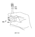
在一些實施例中,本揭示案之裝置及態樣可用於執行各種眼睛注射程序,諸如,例如,涉及藥物產品之玻璃體內注射的眼內治療及手術。本揭示案之裝置及態樣可用於分配具有不同之蛋白質濃度及/或黏度的藥物產品,包括例如,黏度為約1厘泊(centipoise)至約10厘泊、約2厘泊至約9厘泊、約3厘泊至約8厘泊、約4厘泊至約7厘泊或約5厘泊至約6厘泊之藥物產品。亦設想到具有其他黏度之藥物產品。假定被遞送給患者之藥物產品之蛋白質濃度或黏度的可能變化性,用本揭示案之裝置提供精密劑量可能為重要的。本揭示案之裝置及態樣可進一步用於分配不同體積及/或數量之藥物產品,諸如,例如,約1 μL至約200 μL、約10 μL至約190 μL、約50 μL至約150 μL、約75 μL至約125 μL、約90 μL至約110 μL或約100 μL之體積。本揭示案之裝置可經組態且可操作以要求施加超過用於執行一或多個程序(諸如,例如,對裝置灌注、遞送劑量等)之臨限值的最小力。藉由要求施加最小之力,本揭示案之裝置可促進對施用一致劑量之藥物產品的控制,且藉由最小化裝置之組件的意外移動來提高安全性,藉此潛在地減輕患者之疼痛、不適及傷害。In some embodiments, the devices and aspects of the present disclosure can be used to perform various ocular injection procedures, such as, for example, intraocular treatment and surgery involving intravitreal injection of drug products. The device and aspect of the present disclosure can be used to dispense pharmaceutical products with different protein concentrations and/or viscosities, including, for example, a viscosity of about 1 centipoise to about 10 centipoise, and about 2 centipoise to about 9 centipoise. Drug products of about 3 centipoise to about 8 centipoise, about 4 centipoise to about 7 centipoise, or about 5 centipoise to about 6 centipoise. Drug products with other viscosities are also envisaged. Given the possible variability of the protein concentration or viscosity of the drug product delivered to the patient, it may be important to provide a precise dose with the device of this disclosure. The device and aspect of the present disclosure can be further used to dispense pharmaceutical products of different volumes and/or quantities, such as, for example, about 1 μL to about 200 μL, about 10 μL to about 190 μL, about 50 μL to about 150 μL , The volume of about 75 μL to about 125 μL, about 90 μL to about 110 μL or about 100 μL. The device of the present disclosure can be configured and operable to require the application of a minimum force that exceeds a threshold for performing one or more procedures (such as, for example, priming the device, delivering a dose, etc.). By requiring minimal force to be applied, the device of the present disclosure can facilitate the control of administering a consistent dose of the drug product, and improve safety by minimizing accidental movement of the components of the device, thereby potentially reducing patient pain, Discomfort and injury.
對於某些產品,特别係例如眼科或其他藥物產品,劑量準確性可能特別重要。然而,亦可設想到,本揭示案之實施例可適用於任何其他液體產品或任何其他情景,用於設定及施用很準確之劑量或遞送體積之精密方法有益於該等情景。For some products, especially ophthalmic or other pharmaceutical products, the accuracy of dosage may be particularly important. However, it is also conceivable that the embodiments of the present disclosure can be applied to any other liquid products or any other scenarios, and sophisticated methods for setting and administering a very accurate dose or delivery volume are beneficial to these scenarios.
在一些實施例中,根據本揭示案之裝置可根據與某些產品(例如,藥物產品)相關之方法來製造、包裝、填充及/或以其他方式製備,該等裝置可為該等產品之部分。例如,在一些實施例中,可在填充及/或包裝之前或之後對根據本揭示案之裝置進行滅菌。例如,在一些實施例中,根據本揭示案之裝置可被填充及包裝於例如泡罩包裝中,及/或可使用本領域中之任何合適方法進行最終滅菌。例如,根據本揭示案之裝置可使用化學滅菌方法進行最終滅菌,諸如包括環氧乙烷或過氧化氫(例如,汽化之過氧化氫)之方法。在一些實施例中,可使用例如在2018年3月6日申請之國際申請案No. PCT/US2018/021013中描述之方法來對根據本揭示案之裝置進行最終滅菌,該申請案以引用之方式整體併入本文中。In some embodiments, the devices according to the present disclosure can be manufactured, packaged, filled, and/or prepared in other ways according to methods related to certain products (for example, pharmaceutical products), and these devices can be section. For example, in some embodiments, the device according to the present disclosure may be sterilized before or after filling and/or packaging. For example, in some embodiments, the device according to the present disclosure can be filled and packaged in, for example, a blister pack, and/or can be terminally sterilized using any suitable method in the art. For example, the device according to the present disclosure may be terminally sterilized using chemical sterilization methods, such as methods including ethylene oxide or hydrogen peroxide (e.g., vaporized hydrogen peroxide). In some embodiments, the method described in International Application No. PCT/US2018/021013 filed on March 6, 2018 can be used to terminally sterilize the device according to the present disclosure, which is cited as The method is incorporated into this article as a whole.
可市售之劑量遞送裝置(諸如預填充式注射器或與小瓶一起使用之注射器)可能不一定有助於準確地裝載所要體積之物質、對裝置進行灌注、自裝置排出過量之藥物物質及/或自裝置去除氣泡。在特別係容納小體積藥物物質(例如,約500 μL或更少、約300 μL或更少、約250 μL或更少、約200 μL或更少、約150 μL或更少、約100 μL或更少、約50 μL或更少、或約25 μL或更少,諸如在約25 μL與約50 μL之間、在約50 μL與約100 μL之間、在約25 μL與約100 μL之間、在約50 μL與約150 μL之間、在約100 μL與約250 μL之間、在約100 μL與約150 μL之間、在約150 μL與約250 μL之間、在約200 μL與約250 μL之間、在約200 μL與約500 μL之間,或在大約250 μL與大約500 μL之間)之劑量遞送裝置中,亦可能難以用肉眼確認在該裝置中存在恰當劑量之藥物物質。當前在劑量遞送裝置市場中,且尤其係在注射器市場中,需要一些機構,該等機構允許使用者精密地設定以在注射器(例如,預填充或可填充/可再填充注射器)中遞送小體積之產品、對注射器進行灌注、自注射器去除氣泡及/或確認或確保注射器中之劑量體積係恰當的。本揭示案之實施例可幫助製造商、藥物產品提供者、醫學專業人員及/或患者準確地製造、填充或以其他方式製備劑量施用裝置、對裝置進行灌注、自裝置去除氣泡、確認劑量及/或將劑量自裝置施用給患者。此外,本揭示案之實施例可幫助防止或減輕裝置製造或使用中之誤差或變化,諸如劑量線在裝置上之放置的誤差或變化、裝置幾何形狀之變化(例如,注射器頸部幾何形狀之變化)、組件製造容限之變化,及/或產品遞送前設定劑量線之變化或誤差。Commercially available dose delivery devices (such as pre-filled syringes or syringes used with vials) may not necessarily help accurately load the desired volume of substance, prime the device, expel excess drug substance from the device, and/or Remove air bubbles from the device. In a special system containing a small volume of drug substance (for example, about 500 μL or less, about 300 μL or less, about 250 μL or less, about 200 μL or less, about 150 μL or less, about 100 μL or Less, about 50 μL or less, or about 25 μL or less, such as between about 25 μL and about 50 μL, between about 50 μL and about 100 μL, between about 25 μL and about 100 μL Between about 50 μL and about 150 μL, between about 100 μL and about 250 μL, between about 100 μL and about 150 μL, between about 150 μL and about 250 μL, between about 200 μL And about 250 μL, between about 200 μL and about 500 μL, or between about 250 μL and about 500 μL) in a dose delivery device, it may also be difficult to visually confirm the presence of an appropriate dose in the device. Drug substance. Currently in the dose delivery device market, and especially in the syringe market, there is a need for mechanisms that allow users to precisely set to deliver small volumes in syringes (eg, pre-filled or refillable/refillable syringes) The product, filling the syringe, removing air bubbles from the syringe, and/or confirming or ensuring that the dose volume in the syringe is appropriate. The embodiments of the present disclosure can help manufacturers, drug product providers, medical professionals, and/or patients accurately manufacture, fill, or otherwise prepare a dose application device, perfuse the device, remove bubbles from the device, confirm the dose, and /Or administer the dose from the device to the patient. In addition, the embodiments of the present disclosure can help prevent or reduce errors or changes in device manufacturing or use, such as errors or changes in the placement of dose lines on the device, changes in device geometry (for example, the geometry of the syringe neck Changes), changes in component manufacturing tolerances, and/or changes or errors in the set dose line before product delivery.
在一些情況下,本揭示案之實施例可能會對可能難以精密地且準確地設定劑量之個人特別有幫助。例如,本揭示案之實施例可幫助老年人、幼兒或身體或精神殘疾之人設定準確之劑量。In some cases, the embodiments of the present disclosure may be particularly helpful to individuals who may have difficulty setting a dose precisely and accurately. For example, the embodiments of the present disclosure can help the elderly, young children, or people with physical or mental disabilities to set accurate dosages.
本文描述了劑量遞送裝置之各種實施例,且尤其係針對注射器。在一些情況下,本文中揭示之實施例或實施例之態樣可與現有之注射器主體部分結合使用以修改現成之產品,此可減少劑量遞送裝置之開發及製造時間。在其他情況下,本文中揭示之實施例或實施例之態樣可在裝置製造期間包括在裝置中。本文所描述之注射器可為預填充的或者可為可填充/可再填充。Various embodiments of dose delivery devices are described herein, and are specifically directed to syringes. In some cases, the embodiments or aspects of the embodiments disclosed herein can be used in combination with the existing syringe body to modify the ready-made products, which can reduce the development and manufacturing time of the dose delivery device. In other cases, the embodiments or aspects of the embodiments disclosed herein may be included in the device during device manufacturing. The syringes described herein may be pre-filled or may be fillable/refillable.
本揭示案之實施例可包括具有旋轉件、螺紋件、彈簧、齒輪、掣子、通道、凹槽等之注射器,該等注射器可允許使用者精密地控制灌注及劑量遞送元件(諸如,例如,柱塞及/或擋止件)之移動。此類部件可旨在減少人為誤差及/或提高準確性。Embodiments of the present disclosure may include syringes with rotating members, screw members, springs, gears, detents, channels, grooves, etc., which allow the user to precisely control infusion and dose delivery elements such as, for example, Plunger and/or stopper) movement. Such components may be aimed at reducing human error and/or improving accuracy.
在一些實施例中,視覺化裝置,諸如放大鏡,可設置有遞送裝置、附接至遞送裝置或以其他方式安置於遞送裝置上,以便幫助增強該等裝置上之劑量測量標記的可見性。可設想到,一個實施例之態樣(諸如套管、通道、阻擋組件、突起、掣子、螺紋件、抓握、視覺指示器、觸覺指示器或聽覺指示器等)可與一或多個其他實施例之態樣結合,以在單個裝置中產生特徵之各種組合及排列。In some embodiments, a visualization device, such as a magnifying glass, may be provided with, attached to, or otherwise placed on the delivery device to help enhance the visibility of dose measurement markings on the devices. It is conceivable that aspects of an embodiment (such as sleeves, channels, blocking components, protrusions, detents, screws, grips, visual indicators, tactile indicators, or auditory indicators, etc.) can be combined with one or more The aspects of other embodiments are combined to produce various combinations and permutations of features in a single device.
在一些實施例中,根據本揭示案之裝置可被繪示為包括一種類型之柱塞桿及柱塞,或繪示為包括柱塞桿及柱塞之大體示意表示。例如,根據本揭示案之一些裝置可被繪示為或描述為包括例如具有球頭端之柱塞桿,該球頭端與擋止件接合,使得該柱塞桿與該擋止件可附接在一起。可設想到,柱塞桿及擋止件之多種及/或不同組態可適合於本文中揭示之每一實施例。例如,在一些情況下,前述球頭柱塞桿可與本文中揭示之實施例一起使用。在一些實施例中,柱塞桿可未附著至擋止件,而是改為可安置於擋止件附近、緊挨著擋止件安置或與擋止件齊平,使得自柱塞桿朝向擋止件之壓力可推動擋止件,但柱塞桿之撤出、扭轉或其他移動可能不會致使擋止件同樣地被撤出、扭轉或以其他方式移動。作為另一實例,在一些實施例中,柱塞桿可藉由螺紋、夾子或黏合劑附著至擋止件,或可與擋止件成一片(例如,可與擋止件在單個模具中製造)。In some embodiments, the device according to the present disclosure may be illustrated as including one type of plunger rod and plunger, or illustrated as a general schematic representation including the plunger rod and the plunger. For example, some devices according to the present disclosure may be illustrated or described as including, for example, a plunger rod having a ball end that engages with a stopper such that the plunger rod and the stopper can be attached Join together. It is conceivable that multiple and/or different configurations of the plunger rod and the stopper can be adapted to each embodiment disclosed herein. For example, in some cases, the aforementioned ball plunger rod may be used with the embodiments disclosed herein. In some embodiments, the plunger rod may not be attached to the stopper, but instead may be placed near the stopper, next to the stopper, or flush with the stopper, so that it faces from the plunger rod The pressure of the stopper can push the stopper, but the withdrawal, twisting or other movement of the plunger rod may not cause the stopper to be also withdrawn, twisted or moved in other ways. As another example, in some embodiments, the plunger rod can be attached to the stopper by threads, clips or adhesives, or can be integrated with the stopper (for example, it can be manufactured with the stopper in a single mold ).
在一些實施例中,根據本揭示案之裝置可包括與裝置之既定使用者相關的各種修飾特徵。例如,根據本揭示案之裝置可被製造且被出售來用於兒科患者、老年患者或殘疾患者。在此類情況下,根據本揭示案之裝置可包括兒童友好之顏色、卡通影像或對兒童有吸引力之其他修飾特徵、或高對比度之顏色、有紋理之表面、或增強識別及/或使用簡易性之其他特徵。在一些情況下,根據本揭示案之裝置可包括刻字、標誌或被設計為被既定使用者容易辨認出之其他特徵。例如,在兒科裝置或供失能或殘疾人或老年人使用之裝置上之刻字可具有較大、更容易接近之標誌,使得其可被裝置之使用者更容易辨認及閱讀。在一些實施例中,刻字或標誌可為凸起的、模壓的或浮凸的。In some embodiments, the device according to the present disclosure may include various modification features related to the intended user of the device. For example, the device according to the present disclosure can be manufactured and sold for pediatric patients, elderly patients, or disabled patients. In such cases, the device according to the present disclosure may include child-friendly colors, cartoon images, or other decorative features that are attractive to children, or high-contrast colors, textured surfaces, or enhanced recognition and/or use Other features of simplicity. In some cases, devices according to the present disclosure may include lettering, logos, or other features designed to be easily recognizable by a given user. For example, the lettering on a pediatric device or a device for disabled or disabled or elderly people can have a larger, more accessible logo, making it easier to recognize and read by the user of the device. In some embodiments, the lettering or logo may be raised, molded, or embossed.
現在參看圖1A-1E,繪示了遞送裝置1050及組件部件之視圖。裝置1050包括主體1060,及呈凸緣片1070之形式的阻擋組件,該凸緣片具有圍繞開口1073之近側軸環1072 (示出於例如圖3B-3E中),柱塞桿1080可穿過該開口進入主體1060中。柱塞桿1080包括致動部分1082,該致動部分可經致動(例如,推動或扭轉)以使柱塞桿1080旋轉,或將柱塞桿1080沿縱向移動至主體1060中。致動部分1082可經設定大小且經組態以配合(例如,嵌套或以其他方式配合)於近側軸環1072內部。Referring now to Figures 1A-1E, a view of the
裝置1050可為(例如)用於分配預定體積之配製藥物物質的注射裝置,諸如注射器。在一些實施例中,裝置1050可為預填充式注射器。例如,使用者可收到準備好使用之組裝好及包裝好之裝置1050,其中一定體積之配製藥物物質已安置於主體1060中之擋止件1062與主體1060之排出端1064之間。在一些實施例中,氣泡(未圖示)亦可安置於擋止件1062與排出端1064之間。在其他實施例中,裝置1050可為可填充注射器。The
主體1060可為經組態以用於容留及排出預定體積之配製藥物物質的任何合適主體。在一些實施例中,主體1060可具有例如中空之圓柱形部分。主體1060可經組態以在灌注步驟及/或遞送步驟中容留用於遞送給例如患者的任何合適體積之配製藥物物質,且(與裝置1050之其他組件一起)經由例如排出端1064排出預定量之所容留體積。在一些實施例中,主體1060可經組態以容留且(與裝置1050之其他組件一起)排出相對較少體積之配製藥物物質(例如,小於約100 μl,諸如小於約80 μl、小於約60 μl、小於約40 μl、小於約20 μl、小於約10 μl、約95 μl、約90 μl、約85 μl、約80 μl、約75 μl、約70 μl、約65 μl、約60 μl、約55 μl、約50 μl、約45 μl、約40 μl、約35 μl、約30 μl、約25 μl、約20 μl、約15 μl、約10 μl或約5 μl)。裝置1050與其其他組件一起可經進一步組態以使在將預定之小體積遞送給患者之後殘留於主體1060中之配製藥物物質的殘餘體積最少。在一些實施例中,主體1060可為預填充的(例如,在裝置1050完全組裝、包裝、滅菌及/或裝運給使用者之前)。在一些實施例中,擋止件1062可經組態以將預定體積之配製藥物物質容留於主體1060之空腔內部。The
凸緣片1070可為任何合適大小及/或形狀以用作遞送裝置1050中之阻擋組件,以封閉、部分地封閉、遮蓋或部分地遮蓋主體1060的與排出端1064相對之一端,及/或將柱塞桿1080支撐且固持於主體1060內部之適當位置。在一些實施例中,凸緣片1070可包括遠側軸環1075,該遠側軸環經組態以與主體1060接合且相對於主體1060將凸緣片1070固持於適當位置。例如,遠側軸環1075可包括唇緣1071,該唇緣可在主體凸緣1061下面滑動或以其他方式相對於主體凸緣1061滑動,以將凸緣片1070固持於適當位置(例如,以將凸緣片1070可滑動地耦接至主體1060)。在替代實施例中,遠側軸環1075之唇緣1071可由可撓性或半可撓性材料製成,使得其可在主體凸緣1061上面卡扣於適當位置。在其他實施例中,遠側軸環1075或凸緣片1070之另一個部分可黏附至、模製至、或以其他方式附著至主體1060,或可經由摩擦配合與主體1060接合。The
凸緣片1070可為或包括阻擋組件;亦即,凸緣片1070之部分或全部可經設定大小且經組態以在柱塞桿1080相對於凸緣片1070處於某些組態時藉由阻止柱塞桿1080之移動而控制柱塞桿1080之移動。例如,凸緣片1070可經組態以控制柱塞桿1080之旋轉及縱向移動,例如,經由開口1073 (例如,參見圖3B-3E),該開口與柱塞桿1080之部件(例如,頸部1084及致動部分1082,及/或柱塞桿1080之其他部分,如圖3I及圖3M中所示)的大小及形狀互補。如本文中更詳細地描述,凸緣片1070可由各種材料形成,該等材料具有可提供對柱塞桿1080之旋轉或縱向移動之進一步控制的最小強度及/或剛性。例如,凸緣片1070可經組態以至少部分地基於凸緣片1070之材料組成而在達到預定力之前抵制柱塞桿1080向近側移動(或「向後拉」) (例如,以藉由使柱塞桿1080縮回而抑制裝置1050之分解)。應瞭解,凸緣片1070可經組態,使得施加超過該預定力之力可致使凸緣片1070及柱塞桿1080中之一或多者斷裂,藉此使裝置1050變為不可操作的。The
再舉例而言,凸緣片1070可經組態以至少部分地基於凸緣片1070之材料組成而在達到預定力之前抵制柱塞桿1080之旋轉移動(例如,以抑制無意旋轉)。另外地及/或替代地,凸緣片1070可經組態以至少部分地基於凸緣片1070之材料組成而抵制凸緣桿1080向遠側移動以控制劑量遞送之速率(例如,以抑制無意遞送)。裝置1050的除了凸緣片1070之外的各種其他組件可包括提供摩擦干涉以抑制裝置1050之分解、柱塞桿1080之無意旋轉及/或無意劑量遞送的材料組成。For another example, the
凸緣片1070之近側軸環1072可經設定大小且經組態以接納柱塞桿1080之致動部分1082的部分,而阻止柱塞桿1080之突起1086向遠側移動超過預定點,直至柱塞桿1080旋轉至特定位置為止。如圖1A及圖1B中所示,軸環1072可為圓柱形的;在替代實施例中,軸環1072可具有與致動部分1082相配之任何合適之大小或形狀。軸環1072亦可包括空腔,例如,狹槽1074,柱塞桿1080之突起1086可收納於該等狹槽中。狹槽1074可具有面向近側之開口且可具有與裝置1050之縱軸線平行的深度尺寸。狹槽1074之數目及組態可對應於柱塞桿1080上之突起1086的數目及組態。在一些實施例中,狹槽1074可按徑向對稱之組態圍繞軸環1072之外周安置。在其他實施例中,軸環1072可包括僅一個狹槽1074。狹槽1074之深度可對應於柱塞桿1080為了將擋止件1062推向排出端1064且將預定體積之配製藥物物質自主體1060經由排出端1064分配而必須移動的距離。有利地,在製造期間可藉由例如選擇狹槽1074之特定深度來控制將自主體1060分配的該預定體積之配製藥物物質。在一些實施例中,裝置1050可經組態,使得裝置1050之其他部件(例如,主體1060或柱塞桿1080)之製造中的正常變化可能不會導致將自主體1060分配之配製藥物物質的體積之變化。因而,可藉由簡單地改變凸緣片1070之製造來控制該預定體積。The
在一些實施例中,凸緣片1070可包括一或多個凸緣1076,該一或多個凸緣可經設定大小且經組態以幫助使用者固持裝置1050及/或自裝置1050排出配製藥物物質。在一些實施例中,如圖1A-1E中所繪示,凸緣片1070可包括彼此相對且自裝置1050之縱向尺寸垂直地延伸之兩個凸緣1076。在一些實施例中,凸緣片1070可包括一或多個凸緣(諸如四個凸緣)之其他佈置,或自裝置1050之中心縱軸線徑向向外延伸之一個周向凸緣。在一些實施例中,凸緣片1070可自裝置1050之中心總軸線徑向向外延伸至比主體1060之圓周更遠處。在此類實施例中,凸緣片1070在裝置1050放置於表面上時可支撐裝置1050,可防止裝置1050在平坦表面上滾動,及/或可允許裝置1050更易於被拾取。在其他實施例中,凸緣片1070之阻擋組件態樣(例如,軸環1072)可與凸緣片1070分離,使得遞送裝置1050包括單獨之凸緣片及阻擋組件。In some embodiments, the
柱塞桿1080大體上可繞著中心縱軸線旋轉(例如,沿一個方向或沿兩個方向)。在一些實施例中,柱塞桿1080之旋轉可藉由相對於凸緣片1070及/或主體1060來抓住及/或扭轉致動部分1082而完成。在一些實施例中,突起1086可藉由提供額外之表面區域來幫助使用者相對於凸緣片1070及/或主體1060來抓住及/或扭轉致動部分1082,使用者可抓住該額外之表面區域及/或壓在該額外之表面區域上以扭轉致動部分1082。在一些實施例中,柱塞桿1080之僅一個部件或多個部件(例如,致動部分1082及/或頸部1084)可相對於凸緣片1070及/或主體1060旋轉。在一些實施例中,柱塞桿1080可經組態以回應於將預定之扭轉力施加於致動部分1082而相對於凸緣片1070旋轉。凸緣片1070之材料組成可決定使柱塞桿1080相對於凸緣片1070旋轉所需之預定扭轉力。例如,凸緣片1070可由具有預定剛性之各種材料形成,該等材料可對柱塞桿1080產生摩擦阻力以在達到預定之力之前控制柱塞桿1080之旋轉移動(例如,以抑制柱塞桿1080之無意旋轉/意外扭轉)。另外,凸緣片1070之材料組成可提供摩擦容限以在達到預定力之前控制柱塞桿1080之遠側平移(例如,以抑制裝置1050之無意劑量遞送)。The
柱塞桿1080之柄1081可具有適合於配合至主體1060中同時維持堅固(sturdiness)之任何厚度及橫剖面形狀。例如,在一些實施例中,柄1081沿著至少一個維度之厚度可大到可配合且滑動至主體1060中。有利地,此厚度可幫助防止柱塞桿1080相對於裝置1050之其他組件發生不想要之搖晃。在其他實施例中,柄1081可具有較小之厚度,同時仍維持堅固(例如,在裝置1050之組裝及/或使用期間不彎曲、不斷裂或不翹曲)。在一些實施例中,柄1081之各部分可經組態以允許柱塞桿1080相對於凸緣片1070旋轉,而柄1081之其他部分可能不旋轉(例如,參見圖3I-3Q)。The
柱塞桿1080亦可包括遠側尖端1083 (例如參見圖1D),該遠側尖端經設定大小且經組態以推動擋止件1062、附接至擋止件或以其他方式與擋止件介接。尖端1083可具有適合於達成此目的之任何大小或形狀。在一些實施例中,例如,尖端1083可經設定大小且經組態以經由擋止件1062中之開口而夾在擋止件1062上。在其他實施例中,尖端1083可具有經組態以配合至擋止件1062中之開口中的球形形狀。在其他實施例中,尖端1083可呈現與擋止件1062之近側表面平行的平坦表面,且可經組態以在未附接至擋止件1062之情況下將擋止件1062向遠側推動。在其他實施例中,尖端1083可具有適合於將擋止件1062向遠側推動的任何形狀之表面。The
在一些實施例中,柱塞桿1080之頸部1084與凸緣片1070之開口1073可具有互補之幾何形狀,該等幾何形狀視柱塞桿1080相對於凸緣片1070之特定縱向及/或旋轉位置而限制柱塞桿1080 (或其部分)可旋轉之程度及方向。在一些實施例中,柱塞桿1080之致動部分1082與軸環1072亦可包括互補之幾何形狀,該等幾何形狀控制柱塞桿1080可相對於凸緣片1070移動之程度及方向。例如,可基於使用裝置1050之方法(例如,參見相對於圖3A-3F描述之方法及相對於圖3G及圖3H描述之額外/替代方法)的灌注、準備及/或藥物遞送步驟及在此類方法中之每一步驟中的柱塞桿1080之對應位置來限制柱塞桿1080之旋轉及/或縱向移動。例如,一旦裝置1050組裝好,便可限制柱塞桿1080沿近側方向移動到凸緣片1070之外(例如,掉出或被拉出)。此外,在裝置1050處於「灌注」狀態之前及/或在裝置1050處於「遞送」狀態之後,可限制柱塞桿1080繞著縱軸線旋轉。另外,在裝置1050處於「灌注」及/或「遞送」狀態之後可藉由柱塞桿1080之頸部1084與凸緣片1070之開口1073的互補之幾何形狀及/或柱塞桿1080之致動部分1082與凸緣片1070之軸環1072的互補之幾何形狀來限制柱塞桿1080在近側方向上之縱向移動(例如,以「旋出」柱塞桿1080)。有利地,此在柱塞桿1080未固持於主體1060內部之情況下可藉由例如附著至擋止件1062來防止不想要之柱塞桿旋出。例如,在一些實施例中,柱塞桿1080可經組態以簡單地接觸擋止件1062且擱在擋止件1062上,使得柱塞桿1080向近側移動不會將擋止件1062向近側移動。在此類情況下,可藉由柱塞桿1080與凸緣片1070之互補幾何形狀之間的相互作用來防止柱塞桿1080向近側移動。此外,在柱塞桿1080之致動部分1082與凸緣片1070之軸環1072之間的相互作用可限制柱塞桿1080在遠側方向上之縱向移動。作為一實例,在「灌注」狀態之後但在「遞送」狀態之前可限制柱塞桿1080向遠側移動。In some embodiments, the
在移動至「遞送」狀態後,致動部分1082上之突起1086便可與軸環1072之狹槽1074縱向地對準,藉此允許柱塞桿1080之遠側移動自主體1060分配所要體積之藥物物質。因而,柱塞桿1080可包括一定數目及組態之突起1086,使得在柱塞桿1080處於特定位置(例如,「遞送」狀態)時,每一突起1086可向遠側移動至狹槽1074中。在一些實施例中,一個、兩個、三個或更多個突起1086可自致動部分1082延伸,分別對應於一個、兩個、三個或多個狹槽1074。例如,如所繪示,兩個突起1086可按徑向對稱組態自致動部分1082之側延伸(對應於軸環1072中之兩個狹槽1074)。在一些實施例中,多個突起1086 (及狹槽1074)之徑向對稱性可有利地允許突起1086在多種組態中配合至狹槽1074中(例如,視致動部分1082是在一個方向上抑或在另一個方向上扭轉而定)。在此類實施例中,可基於例如使用者偏好、右手型或左手型、或其他因素來在任一方向上扭轉致動部分1082。在一些實施例中,在柱塞桿1080處於「灌注」狀態之後及/或在已自裝置1050遞送所要體積之配製藥物物質之後可藉由將柱塞桿1080壓入主體1060中(例如,歸因於頸部1084及/或開口1073之幾何形狀)而不會將柱塞桿1080向近側拉動或旋出主體1060 (例如,朝向致動部分1082)。After moving to the "delivery" state, the
在一些實施例中,裝置1050可經組態以便於使用,且可包括藉由提供觸覺或視覺回饋來幫助使用者之一或多個特徵。例如,裝置1050之一個、兩個或多個組件可具有對比顏色或紋理。在一些實施例中,例如,凸緣片1070可具有與柱塞桿1080不同之顏色。作為另一個實例,裝置1050之單個組件可具有兩種或更多種顏色或紋理。在一些實施例中,例如,致動部分1082在致動部分1082之遠側部分上可包括第一顏色,在對裝置1050進行灌注時,該第一顏色變成被軸環1072遮蓋;且在致動部分1082之第二部分上包括第二顏色,在對裝置1050進行灌注時,該第二顏色移動到與軸環1072相鄰,以幫助向使用者指示裝置1050已被恰當地灌注。作為另一個實例,在一些實施例中,凸緣片1070可具有與柱塞桿1080及/或主體1060不同之觸感。例如,凸緣片1070可比柱塞桿1080及/或主體1060相對更粗糙或光滑。作為又一實例,裝置1050之一或多個組件可具有幫助固持、抓握、識別或使用裝置1050之紋理。例如,凸緣片1070可具有稍粗糙或凸起之紋理以幫助使用者抓握凸緣1076,及/或防止使用者之手指在使用期間自凸緣1076滑落。在一些實施例中,一些或全部之凸緣片1070可具有光滑感之表面。作為另一個實例,柱塞桿1080之致動部分1082可包括用於幫助抓握及旋轉柱塞桿1080的粗糙或凸起之紋理。例如,如圖1A-1I、圖2A、圖2B及圖3A-3H中所繪示,致動部分1082可在其側上包括周向肋形物。致動部分1082可在其側上具有任何合適數目之肋形物以提供紋理。在其他實施例中,致動部分1082在其側上可不具有肋形物。In some embodiments, the
在一些實施例中,裝置1050或其一或多個組件可包括顏色、標簽或標記,該等顏色、標簽或標記可指示內容或裝置1050之狀態,及/或可指導裝置1050之使用者或向該裝置之使用者提供指示。實例包括用於指示柱塞桿之灌注位置對劑量遞送位置的一或多個標簽、用於指示使柱塞桿1080旋轉或以其他方式移動之方向的一或多個標簽及/或用於指示裝置1050中包括之配製藥物物質之量的一或多個標簽(例如,主體1060上之直線標記)。標簽可例如黏附至裝置1050之組件或印刷在該等組件上,或可壓印在裝置1050之組件上或作為該等組件之部分而模製。在一些實施例中,一或多個有紋理之標簽(例如,壓印或模製於裝置1050上)亦可用作用於幫助使用者抓握或使用裝置1050的有紋理、粗糙或凸起之表面。一或多個示例性標簽可包括文字、數字、指示符及/或符號(例如,線條、掛鎖(padlock)、箭頭、圖等)。In some embodiments, the
在一些實施例中,裝置1050可經組態以在其使用期間發出一種或多種聲音。例如,裝置1050可在灌注步驟完成時或在柱塞桿旋轉至適合於分配預定體積之配製藥物物質之位置時發出「滴答」雜訊。「滴答」雜訊可藉由例如兩個或更多個組件(例如,柱塞桿1080及凸緣片1070)之間的摩擦或一個組件之一部分接觸另一部分(例如,柱塞桿1080之頸部1084接觸凸緣片1070之開口1073)而產生。在一些實施例中,裝置1050可包括在例如柱塞桿1080及凸緣片1070之相鄰表面上的一或多個掣子或突起,該等掣子或突起可在彼此接觸(例如,頸部1084上之翼1089接觸圍繞開口1073之掣子1078,如圖3R-3V中所示)時產生滴答聲。此類聲音可用作用於指示使用者已到達裝置1050之使用中之特定步驟的聽覺回饋。In some embodiments, the
在一些實施例中,裝置1050可包括用於控制柱塞桿1080相對於主體1060之移動的額外特徵或組件。例如,如圖1F中所示,凸緣片1070可包括開口1079,銷1077可穿過該開口而安置。銷1077可經設定大小且經組態以與柱塞桿1080之致動部分1082介接(例如,以滑動至致動部分1082中之開口(未圖示)中),使得在銷1077插入以便接合致動部分1082時,柱塞桿1080可能不會相對於主體1060及凸緣片1070向近側或向遠側移動。在一些實施例中,銷1077亦可防止柱塞桿1080相對於凸緣片1070之旋轉移動。在裝置(例如,圖1A及圖1B中所示之裝置1050)之填充及組裝時可插入銷1077,以防止柱塞桿1080在其使用之前發生不想要之移動。在一些實施例中,銷1077可在裝置1050之包裝、運輸及遞送期間保持插入。在使用裝置1050之前,可移除銷1077或以其他方式對銷進行定位,使得銷不接合致動部分1082。In some embodiments, the
如圖1G及圖1H中所示,在一些實施例中,突起1093可安置於致動部分1082之遠側部分處,在裝置1050之組裝時,該突起可位於凸緣片1070內部。凸緣片1070之向內唇緣1091可懸於突起1093之上,使得可不會將致動部分1082向近側自凸緣片1070拉出。在一些實施例中,突起1093、唇緣1091或該兩者可繞著致動部分1082沿周向安置,使得唇緣1091阻擋突起1093,而不管致動部分1082相對於凸緣片1070之旋轉位置。突起1093及唇緣1091可具有方形橫剖面輪廓(如圖1G中所示)、有角度之橫剖面輪廓(如圖1H中所示)或任何其他合適之橫剖面輪廓。在一些實施例中,突起1093、唇緣1091或兩者之橫剖面輪廓可被選擇為提高製造簡易性(例如,對突起1093或唇緣1091之形狀進行加工或模製),或可被選擇為改良組裝(例如,將柱塞桿1080插入至凸緣片1070中且部分地穿過該凸緣片)。As shown in FIGS. 1G and 1H, in some embodiments, the
如圖1I中所示,在一些實施例中,致動部分1082可包括自突起1093之外周邊徑向向外延伸的一或多個凸出部1096。例如,突起1093可包括繞著突起1093相對於彼此安置於相對位置處之一對凸出部1096。凸出部1096可包括各種合適之大小、形狀及/或橫剖面輪廓。在一些實施例中,凸出部1096可具有圓形形狀,該圓形形狀具有磨圓之外部輪廓,以有助於突起1093在凸緣片1070內移動。As shown in FIG. 11, in some embodiments, the
在本實例中,凸出部1096可沿著突起1093之一側定位,該側與致動部分1082的包括突起1086之對應側縱向地對準。在其他實例中,凸出部1096可沿著突起1093之一側定位,該側偏離致動部分1093的包括突起1086之側(例如,未縱向對準)。凸出部1096可由各種可撓性材料形成,包括例如聚合物,諸如塑膠、橡膠等。應了解,柱塞桿1080在突起1093上或致動部分1082之其他部分上可包括比本文中示出及描述之彼等凸出部更多及/或更少之凸出部1096,而不會脫離本揭示案之範疇。In this example, the
圖1J繪示凸緣片1070之遠端部分,該遠端部分包括沿著內表面之一或多個凹座1097。凹座1097可經設定大小且經整形以在突起1093收納於凸緣片1070內且被定位成與唇緣1091相鄰及/或接觸時收納凸出部1096。應瞭解,唇緣1091可經組態以要求將流體動力施加於柱塞桿1080以將凸出部1096及突起1093收納於唇緣1091遠側且進入凸緣片1070中,藉此對裝置1050進行灌注且抑制柱塞桿1080相對於凸緣片1070之縮回(例如,近側移動)。應瞭解,藉由抑制柱塞桿1080在最初組裝至凸緣片1070中之後被移除,裝置1050可經組態以防止裝置1050在最初使用之後再使用,及/或防止無意中進入空氣而在裝置1050内形成氣泡。在本實例中,凸緣片1070可包括繞著遠端部分相對於彼此按環形陣列安置之複數個凹座1097。該複數個凹座1097可繞著凸緣片1070之圓周彼此間隔開。在一些實施例中,凸緣片1070可包括相對於彼此具有不同之大小及/或形狀之凹座1097。FIG. 1J shows the distal portion of the
如下文更詳細地描述,該複數個凹座1097之一子集可經設定大小且經整形以在突起1093相對於凸緣片1070移動時收納凸出部1096且允許該等凸出部從中穿過。如下文中更詳細地闡釋,該複數個凹座1097之一第二子集可經設定大小且經整形以收納凸出部1096且抑制該等凸出部從中穿過,使得限制突起1093相對於凸緣片1070進一步移動。As described in more detail below, a subset of the plurality of
例如,如圖1K中所示,凸緣片1070包括繞著開口1073 (柱塞桿1080穿過其中而被收納)相對於彼此定位於相對位置處(例如,彼此間隔開約180度)之一對變寬凹座1097a。凸緣片1070進一步包括繞著開口1073相對於彼此定位於相對位置處(例如,彼此間隔開約180度)之一對變窄凹座1097b。凹座1097a可沿著凸緣片1070之圓周與相鄰凹座1097b間隔開約90度來定位。變寬凹座1097a可包括橫向於(例如,垂直於)凸緣1076之縱向長度的中央壁及相對於該中央壁成角度的側壁。變窄凹座1097b可包括平行於凸緣1076之縱向長度的中央壁及垂直於該中央壁之側壁。應了解,變寬凹座1097a可形成相對於變窄凹座1097b而言較大的用於收納凸出部1096之開口。應進一步理解,凹座1097a、1097b之側壁可具有與裝置1050之縱向長度平行的高度。For example, as shown in FIG. 1K, the
在圖1K中所見之第一組態中,柱塞桿1080被收納穿過凸緣片1070,且突起1093相對於開口1073取向,使得凸出部1096收納於變寬凹座1097a内。變寬凹座1097a之有角度側壁可提供空隙以有助於凸出部1096回應於柱塞桿1080相對於凸緣片1070之旋轉而自變寬凹座1097a移出。在此種情況下,在突起1093相對於開口1073旋轉時,凸出部1096可沿著變寬凹座1097a之有角度側壁移動。In the first configuration seen in FIG. 1K, the
如圖1L中所見,在突起1093旋轉時,凸出部1096可鄰接界定開口1073的凸緣片1070之內表面。凸出部1096在相鄰之凹座1097之間移動時可對凸緣片1070產生摩擦干涉。圖1M示出相對於開口1073定位之突起1093,其中凸出部1096與變窄凹座1097b對準且收納於該等變窄凹座中。在此種情況下,柱塞桿1080可經組態以回應於變窄凹座1097b收納凸出部1096而產生可聞及/或觸覺回饋。例如,在凸出部1096收納於變窄凹座1097b中時,可回應於藉由凸緣片1070之內表面施加於凸出部1096之壓力的釋放而發出「滴答」或「卡扣」雜訊。另外地及/或替代地,可回應於凸出部1096在收納於變窄凹座中時展開且撞擊界定變窄凹座1097b之一或多個壁而產生可聞回饋。As seen in FIG. 1L, when the
應了解,在凸出部1096收納於變窄凹座1097b內時,可移除凸出部1096與凸緣片1070之間的摩擦干涉。變窄凹座1097b之側壁可提供抑制凸出部1096之進一步移動的實體限制。在此種情況下,柱塞桿1080可相對於凸緣片1070固定,使得在凸出部1096收納於變窄凹座1097b內時,抑制凸出部1093相對於開口1073進一步旋轉。It should be understood that when the protruding
如圖1N-1P中所示,在一些實施例中,柱塞桿1080可另外地或替代地包括在柄1081上之突起1085,該突起可經組態以與凸緣片1070之開口1073相互作用,使得突起1085可僅向遠側移動穿過開口1073。開口1073之側1092可成角度以在柄1081移動穿過開口1073時允許突起1085向遠側傳遞且阻止突起1085向近側傳遞。突起1085及/或側1092可具有用於達成此目的之任何合適形狀或組態。在一些實施例中,可選擇突起1085及/或側1092之形狀或組態以提高製造簡易性(例如,對突起1085及/或凸緣片1070之形狀進行加工或模製)。As shown in Figures 1N-1P, in some embodiments, the
在其他實施例中,如圖1Q-1T中所見,凸緣片1070可包括可移動桿子1071a。可移動桿子1071a可包括自軸環1072向外延伸之第一端1071b及安置於軸環1072內之第二端1071c。可移動桿子1071a可繞著旋轉銷1071d移動(例如,可樞轉)。第二端1071c可位於開口1073內,使得可移動桿子1071a經組態以在柱塞桿1080收納於凸緣片1070中時與突起1085相互作用。首先參看圖1Q,柱塞桿1080可經組態以藉由將柄1081向遠側平移穿過凸緣片1070直至遇到可移動桿子1071a為止來對裝置1050進行灌注。In other embodiments, as seen in FIGS. 1Q-1T, the
如圖1R中所見,當可移動桿子1071a處於阻礙位置時,第二端1071c可鄰接突起1085。第二端1071c可經組態以當柱塞桿1080處於灌注位置時抑制柱塞桿1080相對於凸緣片1070平移。應了解,第二端1071c與突起1085之間的距離可界定用於移動柱塞桿1080以對裝置1050進行灌注的灌注距離。可移動桿子1071a可經組態以相對於軸環1072且繞著旋轉銷1071d移動(例如,樞轉)以將第二端1071c自阻礙位置移位。旋轉銷1071d延伸時所沿著之樞轉軸線可實質上垂直於柱塞桿1080延伸時所沿著之縱軸線。As seen in FIG. 1R, when the
例如,如圖1S中所見,可回應於將第一端1071b向遠側朝著凸緣1076且繞著旋轉銷1071d移動而致動可移動桿子1071a。在一些實施例中,可回應於接收到由例如裝置1050之使用者對第一端施加的指向遠側之力而致動第一端1071b。第二端1071c可回應於第一端1071b向遠側移動而沿近側方向遠離凸緣1076且相對於旋轉銷1071d移動,藉此致使第二端1071c與突起1085脫離。For example, as seen in FIG. 1S, the
因此,如圖1T中所示,可移動桿子1071a可允許柱塞桿1080相對於凸緣片1070平移,直至突起1085遇到位於開口1073之遠端處的支座1072a為止。在突起1085與支座1072a接合時,支座1072a可致使柱塞桿1080進入柱塞桿1080之劑量完成位置。應了解,第二端1071c與支座1072a之間的距離可界定用於移動柱塞桿1080以自裝置1050分配受控體積之物質的劑量遞送距離。Therefore, as shown in FIG. 1T, the
如圖1U及圖1V中所示,在一些實施例中,柱塞桿1080之致動部分1082可另外地或替代地包括一或多個延伸部1087,該一或多個延伸部經組態以與凸緣片1070之軸環1072中之側部開口1094、1095介接。延伸部1087可自致動部分1082向遠側延伸,且可具有有角度或磨圓之遠側部分,該遠側部分經設定大小且經組態以在將致動部分1082向遠側推動至軸環1072中時朝向柱塞桿1080之中心軸線向內推動。每一延伸部1087之有角度或磨圓之遠側部分可包括鉤子或夾子形部分1087a。另外地,延伸部1087可由可撓性材料製成,允許將延伸部向內推動至軸環1072中且在不再受軸環1072之側限制時向外彈回。軸環1072中之側部開口1094、1095可經設定大小且經組態以收納延伸部1087之鉤子或夾子形部分1087a,使得一旦延伸部1087到達側部開口1094或1095,鉤子或夾子形部分1087a便可向外彈入至側部開口1094或1095中且之後防止柱塞桿1080向近側移動。延伸部1087之數目可與側部開口1094及側部開口1095中之每一者的數目一致,使得在柱塞桿1080相對於凸緣片1070向遠側移動時,每一延伸部1087可同時地收納於對應之側部開口1094或1095中。As shown in FIGS. 1U and 1V, in some embodiments, the
具體而言,第一側部開口1094可經組態以在組裝裝置1050時收納延伸部1087之鉤子或夾子形部分1087a,以在柱塞桿1080插入至隨時可用位置時防止柱塞桿1080向近側移動。在每一延伸部1087之鉤子或夾子形部分1087a收納於第一側部開口1094中時,在該鉤子或夾子形部分與軸環1072介接時可發出「滴答」聲,藉此提供聽覺及/或觸覺回饋,指示該裝置處於隨時可用位置。在一些實施例中,第一側部開口1094可各自圍繞軸環1072之部分圓周延伸,使得延伸部1087之鉤子或夾子形部分1087a可在柱塞桿1080相對於凸緣片1070之旋轉位置的一範圍內收納於側部開口1094中。第二側部開口1095可經組態以在裝置1050處於「遞送」組態時(例如,在灌注及致動部分1082進一步旋轉以使突起1086與狹槽1074對準之後)收納延伸部1087之鉤子或夾子形部分1087a。在圖1U及圖1V中繪示之實施例中,延伸部1087與突起1086縱向地對準,且如圖3C-3F中繪示,側部開口1095同樣地與狹槽1074縱向地對準,以在裝置處於「遞送」組態時允許致動部分1082向遠側進一步移動至軸環1072中。應了解,該裝置可回應於對致動部分1082施加指向遠側之力以克服側部開口1094與延伸部1087之接合且施加旋轉力以克服軸環1072之內部與延伸部1087之間的摩擦力而轉變為「遞送」組態。然而,在其他實施例中,可設想到,延伸部1087及側部開口1094、1095可採取任何合適之互補組態以幫助控制柱塞桿1080之近側移動。Specifically, the
在其他實施例中,如圖1W中所示,側部開口1094可沿著軸環1072定位成與側部開口1095縱向地對準。在收納延伸部1087之鉤子或夾子形部分1087a時,可對裝置1050進行灌注,該等鉤子或夾子形部分最初在側部開口1094近側定位於側部開口1094內。在一些情況下,可回應於延伸部1087收納於側部開口1094內而產生回饋(例如,觸覺、聽覺等)。應理解,軸環1072之近端可回應於鉤子或夾子形部分1087a在側部開口1094處接合至軸環1072而抵制柱塞桿1080相對於凸緣片1070向遠側推進。將指向遠側之力施加於柱塞桿1080可致使延伸部1087自側部開口1094釋放且向遠側平移穿過軸環1072,直至收納於側部開口1095內為止。In other embodiments, as shown in FIG. 1W, the
應了解,使延伸部1087向內偏轉且將鉤子或夾子形部分1087a自側部開口1094釋放所需的指向遠側之力可對應於最小之灌注力及流體動力。因此,在裝置1050之灌注步驟及遞送步驟期間,柱塞桿1080可維持於恆定之徑向取向。在其他實施例中,沿著軸環1072之周向壁可包括更多及/或更少之側部開口,該等側部開口與側部開口1094、1095縱向對準及/或偏離(例如,未縱向地對準)。It should be understood that the distally directed force required to deflect the
如圖1X中所見,替代地,凸緣片1070可包括一或多個內凸出部1095'來替代在上文示出及描述之側部開口1095。在此種情況下,柱塞桿1080可預組裝至凸緣片1070中,其中延伸部1087 (圖1V)擠入至軸環1072中且定位於相對接近側部開口1094處。可藉由將柱塞桿1080向遠側推動穿過凸緣片1070直至延伸部1087收納於側部開口1094內來對裝置1050進行灌注。在一些情況下,可回應於延伸部1087被收納於側部開口1095內而產生回饋(例如,觸覺、聽覺等)。在其他實施例中,側部開口1094可張開,及/或延伸部1087可具有向遠側漸縮之輪廓以促進柱塞桿1080自灌注位置進一步向遠側推進至劑量完成位置。As seen in Figure IX, alternatively, the
柱塞桿1080相對於凸緣片1070之進一步平移可致使延伸部1087朝向彼此徑向向內彎曲,藉此允許柱塞桿1080向遠側平移以自裝置1050遞送劑量。柱塞桿1080可繼續相對於軸環1072向遠側平移,直至鉤子或夾子形部分1087a (圖1V)遇到內凸出部1095'為止。內凸出部1095'可經組態以接觸延伸部1087且將柱塞桿1080固定於劑量完成位置,及/或防止柱塞桿1080相對於凸緣片1070進一步向遠側移動。因此,可藉由內凸出部1095’接合軸環1072內之鉤子或夾子形部分1087a來抑制柱塞桿1080相對於凸緣片1070之進一步移動(例如,近側及/或遠側)。內凸出部1095'可包括互補之鉤子或夾子形部分,該等鉤子或夾子形部分經設定大小及/或整形以與鉤子或夾子形部分1087a或延伸部1087相互作用。應了解,側部開口1094與內凸出部1095'之間的距離可界定用於自裝置1050分配受控體積之物質的劑量遞送距離。Further translation of the
在其他實施例中,如圖2A-2C中所示,凸緣片1070可包括自軸環1072向近側延伸之固定套管1072P。固定套管1072P可具有界定內通道之圓形橫剖面,其中在固定套管1072P之每一末端處具有一開口。固定套管1072P之內通道可延伸穿過固定套管1072P之縱向長度且可與開口1073(圖1O)縱向地對準,使得內通道與開口1073之各別縱向軸線彼此同軸。固定套管1072P可經設定大小、經整形及經組態以收納柄1081。在一些實施例中,固定套管1072P可與軸環1072成一體,而在其他實施例中,固定套管1072P可為組裝至凸緣片1070上之單獨組件。In other embodiments, as shown in FIGS. 2A-2C, the
固定套管1072P可包括複數個開口,該複數個開口經設定大小且經整形以收納突起1085。例如,固定套管1072P可包括彼此縱向間隔開一偏離距離的一對近側開口1072Q及一對遠側開口1072R。另外,該對近側開口1072Q位於彼此相同之縱向位置處,且該對遠側開口1072R位於彼此相同之縱向位置處。如下文更詳細地描述,近側開口1072Q與遠側開口1072R之間的縱向偏離可界定用於移動柱塞桿1080以自裝置1050分配受控體積之物質的劑量遞送距離。替代地,開口1072Q、1072R之間的縱向偏離可界定裝置1050之灌注距離,使得在裝置1050之組裝期間,突起1085最初可收納於近側開口1072Q內以抑制柱塞桿1080向近側縮回。在此種情況下,在突起1085收納於遠側開口1072R內時,劑量遞送距離可對應於在致動部分1082之遠端與軸環1072之底面之間的縱向偏離。雖然未圖示,但應了解,在固定套管1072P上可包括一組額外之開口(例如,在近側開口1072Q近側、在近側開口1072Q遠側及/或在遠側開口1072R遠側)以進一步界定灌注距離及/或劑量遞送距離。The fixed
固定套管1072P之近端可包括界定固定套管1072P之近側開口的有角度之界面1071P。有角度之界面1071P可朝向固定套管1072P之內通道徑向向內漸縮且經組態以引導柄1081及突起1085進入該內通道中。在本實例中,突起1085可沿著相對之側向方向自柄1081徑向向外延伸且可為可壓縮的及/或由可撓性/可變形材料形成,使得突起1085經組態以回應於被施加了力而徑向向內縮回或變形至柄1081中及/或朝向柄1081徑向向內縮回或變形。在其他實施例中,突起1085可經組態以使固定套管1072P至少部分地變形以有助於突起1085朝向開口1072Q、1072R移動及/或在開口1072Q、1072R之間移動。在此種情況下,固定套管1072P可由可撓性材料形成,該可撓性材料可操作以在將指向遠側之力施加於柄1081時徑向向外撓曲,藉此致使突起1085將徑向力施加於固定套管1072P。The proximal end of the fixed
仍參看圖2A,固定套管1072P可經組態以將柱塞桿1080收納穿過該內通道且允許柄1081穿過軸環1072以對裝置1050進行灌注。突起1085可回應於遇到有角度之表面1071P且相對於柄1081徑向向內壓縮直至柱塞桿1080充分地向遠側移動使得突起1085被近側開口1072Q收納為止而收納於固定套管1072P內。如圖2B中所示,突起1085可經組態以在與近側開口1072Q縱向地對準時徑向向外展開(放鬆)以將柄1081相對於凸緣片1070鎖定。在此種情況下,裝置1050可處於灌注位置,使得柄1081相對於固定套管1072P及凸緣片1070向遠側進一步平移可自裝置1050遞送劑量。替代地,裝置1050可被預組裝,其中突起1085收納於近側開口1072Q中,使得柄1081相對於固定套管1072P向遠側平移可對裝置1050進行灌注,直至突起1085收納於遠側開口1072R內為止。Still referring to FIG. 2A, the fixed
如圖2C中所見,在突起1085位於近側開口1072Q內時,將指向遠側之力施加於柄1081可致使固定套管1072P將突起1085徑向向內地壓縮(或變形),藉此允許柄1081相對於固定套管1072P向遠側平移。替代地,可藉由穿過近側開口1072Q施加徑向向內地指向之力來手動地壓縮突起1085(或使之變形)。突起1085可向遠側移動通過固定套管1072P之內通道且可被遠側開口1072R收納。在柄1081相對於軸環1072向遠側平移時,在突起1085收納於遠側開口1072R內時,裝置1050可自灌注位置轉變為劑量完成位置,因此遞送劑量。As seen in Figure 2C, when the
應了解,可基於近側開口1072Q與遠側開口1072R之間的縱向偏離距離來控制藉由裝置1050遞送之劑量的體積。在一些實施例中,固定套管1072P可包括用於在灌注且遞送劑量時收納突起1085以抑制柄1081相對於凸緣片1070向近側縮回(例如,將柱塞桿1080向後拉)的額外開口。例如,在製造階段在裝置1050之組裝期間,突起1085可收納於近側開口1072Q內,使得遠側開口1072R可界定灌注位置,且在遠側開口1072R遠側之第三組開口(未圖示)可界定劑量遞送位置。替代地,在遠側開口1072R遠側的凸緣片1070之底部內表面可界定柱塞桿1080之劑量遞送位置。It should be appreciated that the volume of the dose delivered by the
在一些實施例中,如圖2D-2G中所見,凸緣片1070可包括自軸環1072向遠側且向近側延伸之可移動套管1072S。可移動套管1072S可具有界定內通道之圓形橫剖面,其中在可移動套管1072S之每一末端處具有一開口。可移動套管1072S之內通道可延伸穿過可移動套管1072S之縱向長度。可移動套管1072S可經設定大小、經整形且經組態以被收納穿過開口1073,且可移動套管1072S之內通道可經設定大小以收納柄1081。可移動套管1072S在處於預組裝組態時可相對於軸環1072固定且在與柱塞桿1080接合時可相對於軸環1072移動。In some embodiments, as seen in FIGS. 2D-2G, the
可移動套管1072S可包括複數個開口,該複數個開口經設定大小且經整形以收納突起1085。例如,可移動套管1072S可包括在可移動套管1072S之近端處的近側開口1072U及在可移動套管1072S之遠端處的遠側開口1072T。可移動套管1072S之近端可進一步包括界定可移動套管1072S之近側開口的有角度之界面1071S。有角度之界面1071S可朝向可移動套管1072S之內通道徑向向內漸縮且經組態以引導柄1081及突起1085進入可移動套管1072S之內通道中。在一些實施例中,突起1085可沿著相反方向自柄1081徑向向外延伸,且可為可壓縮的,使得突起1085經組態以回應於被施加了力而壓縮至柄1081中及/或朝向該柄壓縮。The
仍參看圖2D,在處於預組裝位置時,可移動套管1072S之近端可與軸環1072之近端相鄰地定位,且可移動套管1072S之遠端可與軸環1072之遠端相鄰地定位。柱塞桿1080可收納穿過可移動套管1072S之內通道,其中柄1081延伸穿過軸環1072。突起1085可收納於遠側開口1072T內,使得柱塞桿1080可固定至可移動套管1072S。突起1085可經組態以自遠側開口1072T離開且回應於柱塞桿1080相對於可移動套管1072S平移而側向地向外展開。Still referring to Figure 2D, in the pre-assembled position, the proximal end of the
例如,如圖2E中所示,將指向遠側之力施加於致動部分1082可致使突起1085徑向向內地壓縮,藉此允許柄1081相對於可移動套管1072S向遠側平移。在此種情況下,突起1085可自遠側開口1072T離開且在自可移動套管1072S之遠端向遠側平移時展開。裝置1050可回應於柄1081相對於軸環1072向遠側平移直至致動部分1082鄰接可移動套管1072S之近端為止而自預組裝狀態轉變為灌注狀態。在此種情況下,裝置1050可處於灌注狀態,且可藉由可移動套管1072S之存在而抑制柄1081相對於軸環1072之進一步平移。For example, as shown in FIG. 2E, applying a distally directed force to the
現在參看圖2F,柱塞桿1080可回應於柄1081相對於軸環1072向近側平移直至突起1085接合近側開口1072U為止而耦接至可移動套管1072S。應理解,突起1085在平移通過可移動套管1072S之內通道時可處於壓縮狀態且在與之縱向對準時可展開至近側開口1072U中。在突起1085接合至近側開口1072U之情況下,柱塞桿1080相對於凸緣片1070向遠側平移可同時使可移動套管1072S相對於軸環1072移動。應了解,可移動套管1072S與柱塞桿1080之總長度可大於柱塞桿1080單獨之縱向長度。Referring now to FIG. 2F, the
如圖2G中所見,柱塞桿1080可經組態以將可移動套管1072S移動通過凸緣片1070之通道一段預定距離,直至致動部分1082遇到軸環1072之近端為止。柱塞桿1080可經組態以回應於使可移動套管1072S相對於軸環1072向遠側平移而自裝置1050遞送劑量。應了解,可基於在突起1085收納於近側開口1072U內時的致動部分1082與軸環1072之間的預定距離來控制藉由裝置1050遞送之劑量。在一些實施例中,凸緣片1070可經組態以在突起1085收納於近側開口1072U內時抑制可移動套管1072S相對於軸環1072向近側移動。雖然未圖示,但凸緣片1070可包括可操作以限制可移動套管1072S自開口1073向近側縮回的一或多個阻擋組件。As seen in FIG. 2G, the
在其他實施例中,如圖2H-2M中所見,柱塞桿1080可包括位於致動部分1082上之至少一個突起1085W。在該實例中,突起1085W可位於致動部分1082之遠端處或與該致動部分之遠端相鄰地定位,使得突起1085W可回應於柱塞桿1080平移至軸環1072中而收納於凸緣片1070內。In other embodiments, as seen in FIGS. 2H-2M, the
如圖2K中所見,凸緣片1070可包括沿著軸環1072之內表面形成的一或多個通道。具體而言,軸環1072可包括沿著軸環1072之內部形成且具有第一彎曲的第一(近側)螺旋形通道1071W及沿著軸環1072之內部形成且具有與第一螺旋形通道1071W不同及/或相反之彎曲的第二(遠端)螺旋形通道1072W。例如,在自致動部分1082之近端觀看時,第一螺旋形通道1071W可為凹的,而在自相同之有利位置觀看時,第二螺旋形通道1072W可為凸的。或者,在自致動部分1082之近端觀看時,第一螺旋形通道1071W可為凸的,而自相同之有利位置觀看,第二螺旋形通道1072W可為凹的。另外,第二螺旋形通道1072W可與第一螺旋形通道1071W沿縱向間隔開。第一螺旋形通道1071W與第二螺旋形通道1072W可藉由在其間延伸的中間之第三通道1073W連接。As seen in FIG. 2K, the
第三通道1073W可沿著軸環1072之縱軸線或實質上平行於軸環之縱軸線而延伸。應理解,軸環1072上之一或多個通道的大小、形狀及/或取向僅為示例性的,因此可包括其他合適之組態,而不會脫離本揭示案之範疇。如下文詳細地描述,複數個通道1072經組態以收納突起1085W。在一些實施例中,第一螺旋形通道1071W及第二螺旋形通道1072W可為有螺紋的且經組態以與柱塞桿1080之對應組件(例如,突起1085W)嚙合。使突起1085W橫穿通過第一螺旋形通道1071W及第二螺旋形通道1072W可能需要相反之旋轉移動。例如,致動部分之第一旋轉移動(例如,順時針)可致使突起1085W橫穿第一螺旋形通道1071W,而相反之旋轉移動(例如,逆時針)可致使突起1085W橫穿通過第二螺旋形通道1072W。The
參看圖2H,在柱塞桿1080處於就緒位置時,突起1085W可回應於致動部分1082朝向凸緣片1070向遠側平移而收納於軸環1072內。如圖2I中所見,突起1085W可收納於第一螺旋形通道1071W內且回應於柱塞桿1080相對於凸緣片1070之旋轉(例如,沿著第一方向)而從中移動通過。應了解,柱塞桿1080可經組態以在柱塞桿1080在軸環1072內旋轉時歸因於第一螺旋形通道1071W之彎曲而相對於凸緣片1070沿遠側方向軸向地平移。例如,柱塞桿1080可平移藉由第一螺旋形通道1071W之組態界定的第一距離,直至到達第一螺旋形通道1071W之末端為止。該第一距離可對應於裝置1050之灌注步驟,使得裝置1050在突起1085W移動通過第一螺旋形通道1071W時可被至少部分地灌注。Referring to FIG. 2H, when the
現在參看圖2J,突起1085W可位於第一螺旋形通道1071W之末端及第三通道1073W之近端(例如,頂端)處。在一些實施例中,柱塞桿1080可經歷藉由第一螺旋形通道1071W之末端形成的觸覺回饋。如圖2K中所示,柱塞桿1080可向遠側平移通過第三通道1073W以完成裝置1050之灌注步驟。應理解,第一螺旋形通道1071W與第三通道1073W可共同地界定裝置1050之灌注距離,使得在突起1085W平移通道第三通道1073W時,柱塞桿1080處於灌注位置。Referring now to FIG. 2J, the
在突起1085W收納於第二螺旋形通道1072W內之情況下,柱塞桿1080可沿著第二方向(與第一方向相反)旋轉以將柱塞桿1080向遠側平移了第二距離,該第二距離藉由第二螺旋形通道1072W之組態界定。該第二距離可視特定應用及需要而小於、大於及/或實質上等於第二螺旋形通道1072W之縱向尺寸。柱塞桿1080可沿著第二方向旋轉且平移該第二距離,直至到達第二螺旋形通道1072W之末端以自裝置1050遞送劑量為止。應理解,該第二距離可對應於裝置1050之劑量遞送步驟,使得在突起1085W移動通過第二螺旋形通道1072W且到達劑量完成位置時,裝置1050可遞送劑量。With the
在其他實施例中,如圖2L-2O中所見,柱塞桿1080可包括位於致動部分1082上之突起、球形突出物及/或螺紋1085X。在該實例中,螺紋1085X可繞著致動部分1082之圓周且沿著遠端定位,使得螺紋1085X可回應於柱塞桿1080平移至軸環1072中而收納於凸緣片1070內。In other embodiments, as seen in FIGS. 2L-20, the
凸緣片1070可進一步包括螺紋部分1072X,該螺紋部分安置於開口1073内且形成螺旋形路徑,該螺旋形路徑經組態以收納螺紋1085X。在該實例中,螺紋部分1072X可沿著開口1073之近側部分定位,使得開口1073之遠側部分可包括非螺紋部分1071X。如本文中更詳細地描述,螺紋部分1072X可界定與裝置1050之灌注步驟對應的縱向距離,且非螺紋部分1071X可界定與裝置1050之劑量遞送步驟對應的距離。The
例如,如圖2L中所見,致動部分1082可朝向凸緣片1070向遠側平移,直至螺紋1085X遇到軸環1072之遠端為止。柱塞桿1080沿第一方向(例如,順時針或逆時針)旋轉可致使螺紋1085X接合螺紋部分1072X。如圖2M中所示,在螺紋1085X移動通過螺紋部分1072X之螺旋形路徑時,柱塞桿1080之旋轉可使致動部分1082軸向/縱向地平移至軸環1072中。應了解,螺紋1085X旋轉且平移通過螺紋部分1072X可使裝置1050自就緒位置(圖2L)轉變為灌注位置(圖2N)。在螺紋1085X與螺紋部分1072X脫離且沿著非螺紋部分1071X定位之情況下,裝置1050可處於灌注位置。在一些情況下,可回應於螺紋1085W自螺紋部分1072X離開及/或進入非螺紋部分1071X而產生回饋(例如,觸覺、聽覺等)。For example, as seen in FIG. 2L, the
在此種情況下,如圖2O中所示,致動部分1082可相對於凸緣片1070向遠側平移以藉由對致動部分1082施加指向遠側之力來自裝置1050遞送劑量。在螺紋1085X位於非螺紋部分1071X內時,螺紋1085X可移動穿過開口1073之遠側部分。在螺紋部分1072X之遠端與開口1073之遠端之間界定的非螺紋部分1071X之縱向長度可控制裝置1050之劑量遞送。在致動部分1082接合軸環1072的面向近側且在遠側之表面且柱塞桿1080到達劑量完成位置時,裝置1050可完成劑量之遞送。In this case, as shown in FIG. 20, the
圖2P-2T示出凸緣片之其他實施例,除了本文中明確地指出之差異之外,該凸緣片可與上文示出及描述之凸緣片1070類似地組態及操作。應理解,使用類似之元件符號來標示類似之組件,且下文描述之凸緣片可容易地與上文示出及描述的裝置1050之一或多個組件結合。Figures 2P-2T show other embodiments of the flange sheet, which can be configured and operated similarly to the
例如,首先參看圖2P,凸緣片1070A可包括一或多個凸緣1076A,該一或多個凸緣可經設定大小且經組態以幫助使用者握持裝置1050及/或自裝置1050排出配製藥物物質。凸緣1076A可進一步經設定大小及/或經整形以允許使用者以複數個手/抓握位置、佈置及/或取向來握持裝置1050。舉例說明,凸緣1076A可經設定大小及/或經整形,使得可與書寫工具(例如,鉛筆、鋼筆等)類似地握持凸緣片1070A,而不需要使用凸緣1076A,或凸緣片1076A可根據圖24A中所示之實例來設定大小,使得凸緣片1076A可鄰接使用者之一或多根手指。凸緣片1070A可包括一對凸緣1076A,該對凸緣相對於彼此沿相反之徑向方向自軸環1072徑向向外延伸。凸緣1076A可自軸環1072橫向地延伸(例如,凸緣1076A可包括有角度之表面,該有角度之表面沿遠側方向徑向向內傾斜)且經組態以在裝置1050之使用期間抑制使用者之手指自凸緣片1070A滑落。For example, first referring to FIG. 2P, the
凸緣1076A可耦接至彼此以形成相對於軸環1072具有最小半徑的半圓形輪廓。因此,自指凸緣1070A近側之視角來看,凸緣1076A可形成細長輪廓以在使用裝置1050時有助於裝置1050之遠端處的目標治療位點(未圖示)之視覺化。應理解,凸緣片1070A可包括與本文中示出及描述之彼等凸緣數量及/或佈置不同的凸緣1070A之各種其他數量及/或佈置,而不會脫離本揭示案之範疇。在其他實施例中,凸緣1076可包括各種其他合適之大小及/或形狀。The
凸緣片1070A可進一步包括遠側軸環1075A,該遠側軸環自軸環1072向遠側延伸且經組態以接合主體1060以相對於主體1060將凸緣片1070A固持於固定位置。遠側軸環1075A可黏附至、模製或以其他方式附著至主體1060,或可經由摩擦配合來接合主體1060。在該實例中,遠側軸環1075A包括大體上小於軸環1072之縱向長度的縱向長度。在一些實施例中,遠側軸環1075A之大小可被設定為十分小而足以在裝置1050之使用期間有助於主體1060之適當暴露以便使用者抓握及/或操縱。另外,遠側軸環1075A可包括與軸環1072類似及/或不同之材料組成。例如,遠側軸環1075A可由可撓性材料形成,使得遠側軸環1075A可經組態以在將主體1060收納至凸緣片1070A中時徑向向外撓曲且在主體1060被完全收納時徑向向內撓曲以有助於卡扣配合連接(而不會使遠側軸環1075A斷裂)。應了解,在其他實施例中,凸緣片1070A可完全省去遠側軸環1075A。The
在其他實施例中,如圖2Q中所見,凸緣片1070B可包括遠側軸環1075B,該遠側軸環實質上長於上文示出及描述之遠側軸環1075、1075A。例如,遠側軸環1075B可變大而具有大於軸環1072之縱向長度的縱向長度。在該實例中,遠側軸環1075A之大小可被設定為十分大而足以圍住主體1060之大部分長度。在此種情況下,遠側軸環1075B之外表面可提供界面以在裝置1050之使用期間供使用者抓握及/或操縱。另外,遠側軸環1075B可包括擴大之直徑,該直徑超過主體1060之直徑以提供增大之表面區域來用於抓握凸緣片1070B。換言之,遠側軸環1075B可具有變寬之大小及/或形狀以有助於容易地抓握及/或操縱裝置1050。在本實例中,遠側軸環1075B可具有桶形形狀,在自裝置凸緣片1070B之外部觀看時,該桶形形狀具有凸出之外表面。In other embodiments, as seen in Figure 2Q, the
或者,如圖2R中所見,凸緣片1070C可包括遠側軸環1075C,該遠側軸環實質上類似於遠側軸環1075B且包括大於軸環1072之縱向長度的縱向長度。在該實例中,遠側軸環1075C之外表面可經組態以提供界面來在裝置1050之使用期間供使用者抓握及/或操縱。遠側軸環1075C可包括細長輪廓,該細長輪廓之直徑比主體1060之直徑大,使得遠側軸環1075C不會使主體1060之輪廓實質上增大。換言之,遠側軸環1075C可具有相對於遠側軸環1075B變窄之大小。在一些實施例中,遠側軸環1075C可包括在遠端處徑向向外延伸之末端唇緣1077C。末端唇緣1077C可經設定大小、經整形且經組態以增強對遠側軸環1075C之抓握及/或操縱。在本實例中,遠側軸環1075C可具有喇叭形形狀,在自裝置凸緣片1070C之外部觀看時,該喇叭形形狀具有凹入之外表面。Alternatively, as seen in FIG. 2R, the
在圖2S-2T中示出之其他實施例中,凸緣片1070D可包括具有近側唇緣1074D之軸環1072D。近側唇緣1074D可界定不規則表面,該不規則表面經組態以在致動部分1082被軸環1072D收納時與柱塞桿1080介接。例如,近側唇緣1074D可包括一對凹入表面1075D,該對凹入表面沿著近側唇緣1074D沿著彼此相對之側定位。換言之,凹入表面1075D可藉由近側唇緣1074D的未凹入之表面及/或部分間隔開。在該實例中,凹入表面1075D可與狹槽1074相鄰地定位且可界定一通路以用於將柱塞桿1080相對於軸環1072D移動而對裝置1050進行灌注且自該裝置遞送劑量。在一些實施例中,凹入表面1075D可包括螺旋形組態(例如,具有指向遠側之斜坡),使得凹入表面1075D可在第一凸台(ledge)1073D與第二凸台1076D之間沿遠側方向漸縮。In other embodiments shown in FIGS. 2S-2T, the
在一些實施例中,凸緣片1070D可包括視覺化機構,諸如,例如,安置於軸環1072D上以向裝置1050之使用者提供指示的一或多個標簽或標記。例如,該一或多個標簽(例如,數字)可指示為了對裝置1050進行灌注且自裝置1050遞送劑量而使柱塞桿1080相對於凸緣片1070D旋轉或以其他方式移動的方向。舉例而言,該一或多個標簽可包括指示突起1086相對於近側唇緣1074D之開始位置(例如,「1」)、灌注位置(例如,「2」)及劑量遞送位置(例如,「3」)的標記。該一或多個標簽可黏附、印刷、壓印及/或模製至軸環1072D上。In some embodiments, the
如本文中更詳細地描述,凸緣片1070D可經組態以在對裝置1050進行灌注且自裝置1050遞送劑量時允許柱塞桿1080沿單個方向移動。在示例性使用中,柱塞桿1080 (未圖示)最初可被收納穿過凸緣片1070D,且致動部分1082可靠著軸環1072D定位,其中突起1086沿著凹入表面1075D之第一端定位於標記「1」處且與狹槽1074相對。歸因於第一凸台1073D抑制突起1086沿相反方向移動遠離標記「2」,突起1086可僅沿著凹入表面1075D沿單個方向朝向標記「2」旋轉。As described in more detail herein, the
當突起1086沿著凹入表面1075D收納於標記「2」處時,第二凸台1076D可進一步防止突起1086移動通過狹槽1074且經過標記「3」。應了解,近側唇緣1074D之組態為示例性的,使得凸緣片1070D可包括與本文中示出及描述之彼等大小、形狀及/或組態不同的近側唇緣1074D及/或凹入表面1075D之各種其他大小、形狀及/或組態,以在裝置1050之使用期間有助於柱塞桿1080之移動。When the
在其他實施例中,裝置1050之組件可包括一或多個顏色指示符來替代及/或增補上文描述之標記,以向裝置1050之使用者提供指示。例如,裝置1050可包括指示為了灌注且遞送劑量而使柱塞桿1080相對於凸緣片1070D旋轉或以其他方式移動之方向的顏色、符號(例如,箭頭)等。在一個實施例中,柱塞桿1080之外表面可沿著致動部分1082之各種部分具有不同之顏色,以指示柱塞桿1080相對於軸環1072D之各別開始位置(例如,綠色)、灌注位置(例如,黃色)及劑量遞送位置(例如,紅色)。該一或多個顏色指示符可印刷或模製至柱塞桿1080上。在其他實施例中,柱塞桿1080之各个部分可包括不同紋理以替代及/或增補上文描述之顏色指示符,以向裝置1050之使用者提供指示。In other embodiments, the components of the
裝置1050之組件可由任何合適材料製成,且每一組件可由與其他組件相同或不同之材料製成。應了解,在一些實施例中,裝置1050之一或多個組件(例如,凸緣片1070、近側軸環1072、柱塞桿1080、致動部分1082及更多)可由具有足夠之可撓性以在撓曲期間防止斷裂的可撓性材料形成。在一些實施例中,裝置1050之一或多個組件可為剛性的且具有足夠之強度以維持形狀且提供支撐。在其他實施例中,裝置1050之一或多個組件(或一組件之至少一部分)可沿著縱向長度或側向寬度具有變化之剛性,使得該組件可具有可變之可撓性。在其他實施例中,裝置1050之一或多個組件可具有足夠之可撓性以在撓曲期間防止斷裂,同時亦具有足夠之剛性及強度以維持形狀且提供支撐。在一些實施例中,在撓曲及/或與裝置1050之其他組件相互作用時,此類特徵可進一步提供使用者回饋(例如,觸覺、可聞、視覺等)。例如,主體1060、凸緣片1070及柱塞桿1080中之每一者可由包括聚合物之材料製成,諸如塑膠。在一些實施例中,主體1060、凸緣片1070及柱塞桿1080中之一或多者可包括多種不同材料(例如,玻璃、橡膠及/或塑膠)。在一些實施例中,例如,主體1060之圓柱形部分可由玻璃、普列克斯玻璃(Plexiglas)或任何其他合適之聚合物(例如,環烯聚合物或環烯共聚物)或其他材料製成,且擋止件1062可由例如塑膠、橡膠或其他聚合物或共聚物製成。再舉例而言,凸緣片1070可包括聚丙烯均聚物、ABS (丙烯腈、丁二烯及苯乙烯)聚合物、ABS聚碳酸酯摻合物及其他合適材料。在一些實施例中,柱塞桿1080可包括ABS聚碳酸酯摻合物。此類材料可為製造(例如,射出模製)凸緣片1070及/或柱塞桿1080提供較大容限,或有助於提高裝置1050之該等組件的再現性。如上文更詳細地描述,在一些實施例中,裝置1050之一或多個組件可由可撓性及/或可變形材料組成形成,該材料組成提供在對裝置1050進行灌注且自裝置1050遞送劑量時撓曲該等組件或使該等組件變形(例如,不會斷裂)的較大容限。The components of the
在一些實施例中,經組態以容納配製藥物物質的主體1060之一部分可由透明或半透明材料製成。在一些實施例中,凸緣片1070與柱塞桿1080可由相同、類似或不同之材料製成,諸如類似或不同之塑膠(例如,各自具有類似或不同之硬度)。在一些實施例中,裝置1050之組件可包括彈性材料。例如,裝置1050之部件可包括橡膠或塑膠,該橡膠或塑膠經組態以允許使用者更好地握住裝置1050或在裝置1050之兩個組件之間(例如,在主體1060與擋止件1062之間)產生氣密或其他密封配合。在一些實施例中,一部分或全部之柱塞桿1080 (例如,致動部分1082及/或延伸部1087,或者整個柱塞桿1080)可由具有一定程度之可撓性的材料製成,例如,以允許延伸部1087彎曲。上文列出之材料中的一或多種(例如,塑膠、橡膠、聚合物或共聚物)可具有此類特性。在一些實施例中,一部分或全部之裝置1050可適合於滅菌,例如,熱或化學滅菌。In some embodiments, a portion of the
圖2A及圖2B繪示了組裝圖1A-1E中繪示之遞送裝置的示例性方法。如圖2A中所示,凸緣片1070可組裝至主體1060。凸緣片1070至主體1080之組裝可包括將該兩個組件滑動、卡扣、黏附或以其他方式附著在一起。如圖2A中所繪示,凸緣片1070可滑動至主體1060上,例如,使得凸緣片1070之唇緣1071與主體凸緣1061接合。柱塞桿1080可插入穿過組裝好之凸緣片1070及主體1060,使得柱塞桿1080之遠端接觸擋止件1062。組裝好之裝置1050隨後可處於適合於包裝、滅菌及/或使用之組態。Figures 2A and 2B illustrate an exemplary method of assembling the delivery device illustrated in Figures 1A-1E. As shown in FIG. 2A, the
圖3C-3F繪示組裝裝置1050之示例性方法,其中致動部分1082包括延伸部1087,且軸環1072包括側部開口1094。在此類實施例中,柱塞桿1080可插入穿過凸緣片1070,直至延伸部1087的鉤子或夾子形部分收納於側部開口1094內為止,此時,組裝好之裝置1050可處於適合於包裝、滅菌及/或使用之組態。應了解,側部開口1094可經組態以在延伸部1087之鉤子或夾子部分收納於其中時抑制柱塞桿1080相對於凸緣片1070向近側縮回。在裝置1050被置於初始組裝狀態時,側部開口1094可用作第一鎖,以防止裝置1050之分解。3C-3F illustrate an exemplary method of assembling the
如本文中更詳細地描述(參見圖4G-4J),側部開口1095可經組態以在延伸部1087之鉤子或夾子部分收納於其中時抑制柱塞桿1080向近側縮回。在裝置1050被置於劑量遞送狀態時,側部開口1095可用作第二鎖,以防止在完成藥物/藥劑遞送之後抽取患者體液。應了解,側部開口1094、1095可產生指示柱塞桿1080與凸緣片1070之相對位置的回饋,諸如,例如,可聞回饋、觸覺回饋等。在一些實施例中,裝置1050可包括比本文中示出及描述之彼等側部開口多及/或少的側部開口1094、1095,以增加及/或減小裝置1050上之鎖的數量。As described in more detail herein (see FIGS. 4G-4J), the
在一些實施例中,組裝裝置1050可包括在將其與凸緣片1070及擋止件1080組合之前預先填充主體1060;例如,可將預定量之藥物物質安置於主體1060中之擋止件1062與針尾1064之間。在一些實施例中,視裝置1050之組件之結構的預期變化而定,可採用裝置1050之組件的替代組裝次序。例如,在凸緣片1070經組態以使用卡扣配合接合件組裝至主體1060之實施例(未圖示)中,可首先將柱塞桿1080插入穿過凸緣片1070,且可將組合之凸緣片1070與柱塞桿1080組裝至主體1060,例如,使得凸緣片1070卡扣於主體1060之近側主體凸緣1061上面,且柱塞桿1080插入至主體1060中。In some embodiments, the
圖4A-4F繪示了根據本揭示案之態樣的使用裝置1050之示例性方法。在圖4A中繪示之使用前組態下,裝置1050可將一定體積之藥物物質容留於擋止件1062與排出端1064之間。在突起1086與近側軸環1072之近端之間可存在灌注距離p
,且突起1086可與狹槽1074未對準。在圖4B中繪示之灌注步驟中,柱塞桿1080可沿縱向進一步移動至主體1060中。例如,使用者可將致動部分1082部分地壓到凸緣片1070之近側軸環1072中。在一些實施例中,裝置1050在此步驟期間可保持於倒置位置,以在藉由柱塞桿1080將擋止件1062向遠側推動時,確保可經由排出端1064排出截留於主體1060中之空氣。在圖4A之使用前組態下且在圖4B中所示之灌注步驟期間,歸因於凸緣片1070中之開口1073及柱塞桿1080之頸部1084的幾何形狀(如圖4B中之頂部橫剖面圖中所示),可防止柱塞桿1080繞著注射器之縱軸線旋轉。如圖4C中所示,在柱塞桿1080之突起1086鄰接近側軸環1072之近端時,可停止灌注步驟。在灌注步驟完成時,柱塞桿1080之頸部1084可相對於凸緣片1070之開口1073沿縱向定位,使得其現在可相對於凸緣片1070旋轉。例如,在灌注步驟完成時,與裝置處於使用前組態時相比,頸部1084之較窄部分可安置於開口1073內部。4A-4F illustrate an exemplary method of using the
如圖4D中所繪示,裝置1050可處於灌注組態。在圖4E中繪示之分配準備步驟中,柱塞桿1080可繞著縱軸線旋轉以使突起1086與狹槽1074對準。為此,使用者可抓住且扭轉致動部分1082。在一些實施例中,如別處已描述的,有可能在任一方向上扭轉致動部分1082以使突起1086與狹槽1074對準。在其他實施例中,致動部分1082可僅能在一個方向上旋轉。在一些實施例中,一旦突起1086與狹槽1074對準,柱塞桿1080相對於凸緣片1070之進一步旋轉可由於例如頸部1084與開口1073之幾何形狀之間的接觸而停止。因此,使突起1086與狹槽1075對準可將裝置1050鎖定於隨時分配組態。在一些實施例中,致動部分1082之旋轉可使突起1086與狹槽1074對準,且可允許柱塞桿1080相對於凸緣片1070在縱向上維持固定(例如,致動部分1082之旋轉不會造成柱塞桿1080向近側或向遠側移動)。如圖4F中所繪示,在分配步驟中,柱塞桿1080可沿縱向進一步移動至主體1060中。例如,使用者可將致動部分1082向遠側壓到凸緣片1070之近側軸環1072中,使得突起1086滑動至狹槽1074中。一旦突起1086鄰接狹槽1074之遠端,柱塞桿1080之進一步遠側移動便停止。該分配步驟可確保自裝置1050分配主體1060內部的預定體積之藥物物質。在一些實施例中,當突起1086鄰接狹槽1074之遠端時,擋止件1062不會「觸底」或鄰接主體1060中之排出端1064的內部。有利地,藉由確保在擋止件1062可觸底之前自裝置1050分配主體1060內部的預定體積之藥物物質,排出端1064之製造中的任何變化(例如,更改排出端1064之確切大小或形狀)不太可能影響自裝置1050遞送的藥物物質之預定體積。實際上,在一些實施例中,自裝置1050遞送的藥物物質之預定體積可能不會受裝置1050之任何組件之製造中的典型變化影響,尤其係除了凸緣片1070外之任何組件。有利地,此可允許在裝置1050之若干組件中存在製造變化(例如,在玻璃主體1060或其他玻璃組件之形成中的變化)的不同或較大之容限,而不會影響將自裝置1050遞送的藥物物質之預定體積。As shown in Figure 4D, the
在一些實施例中,在使用裝置1050過程中之一或多個步驟之後,可防止使用者重做一步驟,及/或防止使用者撤銷一或多個步驟。例如,(例如)柱塞桿頸部1084及開口1073之幾何形狀可防止使用者將柱塞桿1080自主體1060向近側拉動(例如,自主體拉出)、使柱塞桿1080提前旋轉(例如,在圖4C中所示之灌注步驟之前)及/或在分配準備步驟(例如,示出於圖4E中)期間使柱塞桿1080過度旋轉。明確而言,圖4G-4J繪示在使用裝置1050之一實施例過程中的步驟,該裝置在致動部分1082上具有延伸部1087且在凸緣片1070之軸環1072中具有對應之側部開口1094、1095。圖4G及圖4H繪示在將致動部分1082向遠側推動至軸環1072中時的裝置1050。歸因於其有角度之遠側部分,延伸部1087被向內推動至軸環1072中。一旦柱塞桿1080已旋轉至「遞送」位置且致動部分1082被向遠側進一步推動至軸環1072中以自裝置1050遞送預定體積之藥物物質,延伸部1087即可收納於側部開口1095中(示出於圖4I及圖4J中),其後限制柱塞桿1080向近側移動。有利地,限制柱塞桿1080向近側移動可防止材料無意中自例如藥物物質遞送至之位點撤回裝置1050中。在一些實施例中,裝置1050可包括側部開口1094或側部開口1095。在其他實施例中,如圖4G-4J中所示,裝置1050可包括側部開口1094與側部開口1095。In some embodiments, after one or more steps in the process of using the
圖4K及圖4O繪示了頸部1084之幾何形狀的其他詳細示例性態樣,該頸部之幾何形狀可幫助控制柱塞桿1080之移動。例如,如圖4L中所示,頸部1084之最近側部分a
及柄1081 (由圖4K中之部分d
指示)均可具有第一橫剖面形狀。此形狀可允許柱塞桿1080之對應部分向近側/向遠側移動穿過阻擋組件(例如,凸緣片1070)之開口(例如,開口1073),但可防止柱塞桿1080繞著縱軸線旋轉。如圖4M中所示,頸部1084之窄部分b
可具有較小之橫剖面形狀。在安置於阻擋組件(例如,凸緣片1070)之開口(例如,開口1073)中時,此形狀可允許柱塞桿1080繞著縱軸線單向或雙向地旋轉。應了解,允許柱塞桿1080平移旋轉之頸部1084之各別部分(例如,在窄部分b
處)可具有一幾何形狀,相對於柱塞桿1080之其他部分的橫剖面形狀,該幾何形狀具有較小之橫剖面形狀以允許有較大之空間用於此類移動。如圖4N中所示,頸部1084之第三部分c
可具有較大之橫剖面形狀,該橫剖面形狀可與阻擋組件(例如,凸緣片1070)之開口(例如,開口1073)的大小及形狀完全對應。因而,僅在柱塞桿1080相對於凸緣片1070處於特定之旋轉取向時才可能發生頸部1084之此部分向近側或向遠側移動穿過開口1073。此外,在頸部1084之部分c
安置於開口1073內時,柱塞桿1080將不可旋轉。此可確保(例如)在柱塞桿1080可旋轉之前柱塞桿1080相對於凸緣片1070處於所要位置(例如,灌注完成且部分c
不再安置於開口1073內)。共同地,頸部1084之各種橫剖面形狀及開口1073之大小及形狀可相結合以產生對裝置1050進行灌注且自裝置1050遞送藥物物質所需的柱塞桿1080之移動的特定序列。在該實例中,開口1073之遠側部分可相對於開口1073之中間及/或遠側部分具有最大之橫剖面輪廓,以適應從中穿過之柱塞桿1080的各種各樣之幾何形狀(例如,頸部1084、柄1081等)。4K and FIG. 40 illustrate other detailed exemplary aspects of the geometry of the
在圖4O中繪示之另一個實施例中,如圖4P中所示,頸部1084之最近側部分e
及柄1081之主要部分h
均可具有第一橫剖面形狀。此形狀可允許柱塞桿1080之對應部分向近側/向遠側移動穿過阻擋組件(例如,凸緣片1070)之開口(例如,開口1073),但可防止柱塞桿1080繞著縱軸線旋轉。如圖4Q (相對於凸緣片1070處於旋轉前組態)及圖4R (相對於凸緣片1070處於旋轉後組態)中所示,頸部1084之窄部分f
可具有較小之翼狀(或箭頭形狀)橫剖面形狀。在安置於阻擋組件(例如,凸緣片1070)之開口(例如,開口1073)中時,此「翼狀」形狀可允許柱塞桿1080繞著縱軸線單向地或雙向地旋轉,且在旋轉已完成之後可限制或抵制柱塞桿1080在相反方向上「向後」旋轉(如相對於圖4T-4X進一步描述)。如圖4S中所示,柱塞桿1080之部分g
及l
可具有較大之橫剖面形狀,該橫剖面形狀可與阻擋組件(例如,凸緣片1070)之開口(例如,開口1073)的大小及形狀完全對應。因而,僅在柱塞桿1080相對於凸緣片1070處於特定之旋轉取向時才可能發生柱塞桿1080之此等部分向近側或向遠側移動穿過開口1073。此外,在柱塞桿1080之部分g
或l
安置於開口1073內時,柱塞桿1080將不可旋轉。此可確保(例如)在裝置1050之組裝及使用期間的某些步驟時柱塞桿1080相對於凸緣片1070處於所要位置,允許精密地組裝及使用裝置1050。另外,部分g
及l
之「較大」橫剖面區域可有助於防止柱塞桿「旋出」,因為除非相對於凸緣片1070處於特定之旋轉位置,否則該等部分將無法向近側移動穿過開口1073。例如,在柱塞桿1080自「灌注」位置旋轉至「遞送」位置之後,柱塞桿1080之部分g
可能無法移動穿過開口1073,因此在裝置1050之該使用階段時防止柱塞桿「旋出」。共同地,柱塞桿1080之各種橫剖面形狀及開口1073之大小及形狀可相結合以產生組裝裝置1050、對裝置1050進行灌注且自裝置1050遞送藥物物質所需的柱塞桿1080之移動的特定序列。In another embodiment shown in FIG. 4O, as shown in FIG. 4P, the proximal part e of the
圖4T-4X更詳細地繪示了頸部1084之翼形部分與凸緣片1070中之開口1073之間的特定相互作用。凸緣片1070可包括與開口1073相鄰或在開口1073內之掣子1078,該等掣子可與頸部1084上之翼1089介接。圖4T繪示了在旋轉前組態中(例如,在裝置1050已被灌注之後但在柱塞桿1080已相對於凸緣片1070旋轉至「遞送」組態之前)在開口1073內部之頸部1084的橫剖面圖。圖4U繪示了在柱塞桿1080繞著縱軸線旋轉時,翼1089中之一者可接觸掣子1078中之一者(視旋轉方向而定)。在旋轉繼續時,掣子1078中之一者可致使翼1089中之一者朝向頸部1084之其餘部分壓縮。在旋轉完成時,翼1089中之一者已經過掣子1078中之該一者且已展開。翼1089經過掣子1078之此展開可導致可聞之「滴答」回饋及/或觸覺回饋以指示旋轉完成,且之後可防止柱塞桿1080相對於凸緣片1070「向後」旋轉。翼1089及掣子1078可經組態為以類似方式相互作用,而不管柱塞桿1080是按順時針抑或逆時針方向旋轉,藉此允許柱塞桿1080雙向地旋轉以將柱塞桿1080自「灌注」位置移動至「遞送」位置。如圖4X中更詳細地示出,每一翼1089可具有磨圓之形狀以允許在一個方向上容易旋轉,且翼1089展開經過掣子1078可將翼1089相對於掣子1078放置於某位置,該位置極大地抵制或以其他方式禁止在相反方向上旋轉。掣子1078可具有經組態以幫助翼1089單向地移動經過掣子1078的任何合適之外形。4T-4X illustrate the specific interaction between the wing-shaped portion of the
有利地,本文中描述的柱塞桿1080之各種組態可允許對一個件(例如,柱塞桿1080)或兩個件(例如,柱塞桿1080及凸緣片1070)進行模型化、模製及/或製造以便達成若干目標—例如,控制所要之柱塞桿移動及組裝、減少使用者出錯、防止柱塞桿旋出及最小化為了組裝裝置1050而需要製造及處理的各不相同之部件的數目。Advantageously, the various configurations of the
在一些實施例中,如圖4Y-4Z中所見,裝置1050可在一個套組中包括一對柱塞桿,該對柱塞桿可與單個致動部分1082互換,或耦接至單獨之致動部分1082。例如,首先參看圖4Y,裝置1050可包括第一柱塞桿1080A,除了本文中明確地指出之差異之外,該第一柱塞桿實質上類似於上文示出及描述之柱塞桿1080。第一柱塞桿1080A可包括柄1081A,該柄具有界定於致動部分1082之遠端與尖端1083A之間的縱向長度A。如下文詳細地描述,縱向長度A可界定用於使柱塞桿1080A相對於凸緣片1070移動以對裝置1050進行灌注的灌注距離。尖端1083A可具有平坦及/或平面之界面,該界面可經組態以在第一柱塞桿1080A收納於主體1060內時抑制擋止件1062之接合。In some embodiments, as seen in Figs. 4Y-4Z, the
現在參看圖4Z,裝置1050可進一步包括第二柱塞桿1080B,該第二柱塞桿實質上類似於柱塞桿1080。第二柱塞桿1080B可包括柄1081B,該柄自致動部分1082向遠側延伸且具有界定於致動部分1082之遠端與尖端1083B之間的縱向長度B。尖端1083B實質上類似於上文描述之尖端1083A。柄1083B之縱向長度B與柄1081A之縱向長度A相比相對較大且可界定用於使柱塞桿1080A相對於凸緣片1070移動以自裝置1050遞送劑量的劑量遞送距離。Referring now to FIG. 4Z, the
第一柱塞桿1080A可經組態以回應於將柄1081A平移穿過軸環1072且進入主體1060中而對裝置1050進行灌注(參見圖1A-1B)。在此種情況下,尖端1083A可接觸擋止件1062且將擋止件向遠側推動該灌注距離。應理解,可基於第一柱塞桿1080A之縱向長度A的大小來控制裝置1050之灌注距離。在對裝置1050進行灌注時,可自主體1060及凸緣片1070移除第一柱塞桿1080A,而不會歸因於尖端1083A的變平之界面使擋止件1062縮回。因此,在第一柱塞桿1080A縮回時,止擋件1062可相對於主體1060保持於固定位置。The
在使用柄1081A進行上文描述之灌注步驟之後,第二柱塞桿1080B可經組態以回應於將柄1081B平移穿過軸環1072且進入主體1060中而自裝置1050遞送劑量(參見圖1A-1B)。在此種情況下,尖端1083B可接觸擋止件1062且將擋止件向遠側推動該劑量遞送距離。應理解,可基於第二柱塞桿1080B之縱向長度B的大小來控制裝置1050之劑量遞送距離。該劑量遞送距離可實質上等於柄1081B與柄1081A之間的長度差。After performing the above-described perfusion step using the
圖5A-5C繪示了根據本揭示案之額外實施例的另一個示例性遞送裝置1200。裝置1200包括主體1220及具有近側軸環1242之凸緣片1240,內軸環1260可安置於該近側軸環中。共同地,近側軸環1242與內軸環1260可形成用於裝置1200之阻擋組件。柱塞桿1280可穿過內軸環1260及凸緣片1240,進入主體1060中。柱塞桿1280可與近側軸環1242及內軸環1260之中心軸線共用縱軸線,且可具有致動部分1282,該致動部分經設定大小且經組態以配合(例如,嵌套或以其他方式配合)於內軸環1260內部。5A-5C illustrate another
裝置1200可例如為用於分配預定體積之配製藥物物質的注射裝置,諸如注射器。大體上,裝置1200可與裝置1050或與本文中揭示之其他遞送裝置共用大小、容量、材料、製備、組裝、製造、操作或使用特性。與裝置1050一樣,裝置1200可經組態以便於使用且可包括一或多個特徵,該一或多個特徵藉由提供觸覺、聽覺或視覺回饋(例如,使用本文中別處所描述之任何特徵)來幫助使用者。The
主體1220可具有與例如裝置1050之主體1060或與本領域中已知之任何注射器主體相同的任何或所有特性。例如,在一些實施例中,主體1220可為可預填充的或被預填充(例如,在完成裝置1200之組裝、包裝、滅菌及/或運送給使用者之前可預填充或被填充有藥物物質)。在一些實施例中,擋止件1222可經組態以插入於主體1220中且可經組態以在主體1200內部在擋止件1222與排出端1224之間容留預定體積之配製藥物物質。The
凸緣片1240可為任何合適之大小及/或形狀以閉合、部分地閉合、遮蓋或部分地遮蓋主體1220的與排出端1224相對之末端及/或在主體1220內部將柱塞桿1280支撐且固持於適當位置。在一些實施例中,凸緣片1240可與裝置1050之凸緣片1070共用一些特性。例如,凸緣片1240可包括遠側軸環1244,該遠側軸環經組態以與主體1220接合且相對於主體1220將凸緣片1240固持於適當位置。例如,遠側軸環1244可包括唇緣1245,該唇緣可在主體凸緣1226上面滑動,以將凸緣片1240固持於適當位置。在替代實施例中,遠側軸環1244之唇緣1245可由可撓性或半可撓性材料製成,使得其可在主體凸緣1226上面卡扣於適當位置。在其他實施例中,遠側軸環1244或凸緣片1240之另一部分可黏附至、模製至或以其他方式附著至主體1220,或可經由摩擦配合與主體1220接合。The
在一些實施例中,凸緣片1240可包括一或多個凸緣1246,該一或多個凸緣可經設定大小且經組態以幫助使用者固持裝置1200及/或自裝置1200排出配製藥物物質。在一些實施例中,如圖1A-1E中所繪示,凸緣片1240可包括兩個凸緣1246,該兩個凸緣彼此相對且自裝置1200之縱向尺寸垂直地延伸。在一些實施例中,凸緣片1240可包括一個凸緣或多個凸緣(諸如四個凸緣)之其他佈置,或自裝置1200之中心縱軸線徑向向外延伸之一個周向凸緣。在一些實施例中,凸緣片1240可自裝置1200之中心縱軸線徑向向外延伸到比主體1220之圓周更遠處。在此類實施例中,凸緣片1240在裝置1200放置於表面上時可支撐裝置1200,或可防止裝置1200在平坦表面上滾動,及/或可允許裝置1200更易於被拾取。In some embodiments, the
在一些實施例中,凸緣片1240及內軸環1260可經設定大小且經組態以(例如)藉由限制及/或引導柱塞桿1280之旋轉及縱向移動而用作裝置1200中之阻擋組件。凸緣片1240之近側軸環1242可經設定大小且經組態以接納內軸環1260之部分,而阻止突起1262向遠側移動,直至內軸環1260旋轉至特定位置為止。轉而,內軸環1260可經設定大小且經組態以收納柱塞桿1280之致動部分1282的部分或全部。如圖5A-5C中所示,近側軸環1242、內軸環1260及致動部分1282皆可具有大體上圓柱形之形狀;在替代實施例中,近側軸環1242、內軸環1260及致動部分1282中之每一者可具有允許致動部分1282配合(例如,嵌套)於內軸環1260內且允許內軸環1260配合於近側軸環1242內的任何合適之大小或形狀。In some embodiments, the
柱塞桿1280及內軸環1260大體上可繞著共用之中心縱軸線旋轉(例如,在一個方向上或在兩個方向上)。此外,柱塞桿1280與內軸環1260可沿著該中心縱軸線移動(例如,沿遠側方向)以對裝置1200進行灌注及/或自主體1220之遠端1224遞送一定體積之藥物物質。柱塞桿1280之致動部分1282可包括一遠側幾何形狀,在致動部分1282向遠側移動至內軸環1260時,該遠側幾何形狀與內軸環1260介接以防止柱塞桿1280自內軸環1260向近側移動(例如,旋出)。例如,致動部分1282可包括一楔形遠側部分,該楔形遠側部分在經過內軸環1260之遠側部分時自內軸環1260向遠側展開,使得致動部分1282可不再相對於內軸環1260自由地移動。The
凸緣片1240可包括空腔,諸如,狹槽1248,在內軸環1260旋轉至特定位置時,內軸環1260之突起1262可滑動至該等空腔中。與裝置1050之狹槽1074一樣,狹槽1248可具有與裝置1200之縱軸線平行的深度尺寸,且狹槽1248之深度可對應於柱塞桿1280為了將擋止件1222朝向排出端1224推動且經由排出端1224自主體1220分配預定體積之配製藥物物質而必須向遠側移動的距離。The
在一些實施例中,裝置1200可具有額外特徵。例如,在一些實施例中,柱塞桿1280之頸部可具有與凸緣片1240之開口互補的幾何形狀,與裝置1050之頸部1084及開口1073類似,該幾何形狀限制柱塞桿1280可縱向地旋轉或移動之程度及方向。例如,可基於在裝置1200之使用期間的灌注、準備及/或藥物遞送步驟來限制柱塞桿1280之旋轉及/或縱向移動。作為另一個實例,可在裝置1200之準備或使用期間的任何點時防止柱塞桿1280被拉出或旋出主體1220。In some embodiments, the
在裝置1200之預期使用方法中,裝置1200可被填充有預定體積之藥物物質。該藥物物質之預定體積可大於適合於遞送給患者之藥物物質體積。在一些實施例中,裝置1200 (例如,主體1220)可含有預定體積之藥物物質及氣泡(未圖示),在將藥物物質遞送至患者之前應去除該氣泡。在一些實施例中,裝置1200可為預填充式注射器。為了對裝置1200進行灌注(例如,如果有任何氣泡則去除氣泡且確保將合適體積之藥物物質遞送給患者),使用者可將柱塞桿1280之致動部分1282推動至內軸環1260中。致動部分1282之幾何形狀可與內軸環1260相互作用(例如,致動部分1282之遠側楔或夾子可在內軸環1260之遠側上展開)以將致動部分1282固定於內軸環1260中及/或固定至內軸環1260且防止柱塞桿1280旋出。此時,裝置1200可處於「灌注」狀態。隨後,內軸環1260可繞著縱軸線旋轉,直至突起1262變成與狹槽1248縱向地對準。此時,裝置1200可處於「遞送」狀態。為了自裝置1200遞送預定體積之藥物物質,內軸環1260與致動部分1282及柱塞桿1280一起可隨後向遠側移動,直至突起1262鄰接狹槽1248之遠端為止。柱塞桿1280在此步驟中行進之距離可將擋止件1222向遠側推動一距離,自裝置1200之排出端1224分配預定體積之藥物物質需要該距離。In the intended use of the
現在參看圖6A-6E,繪示了遞送裝置1300及組成部分之視圖。遞送裝置1300包括:阻擋組件,該阻擋組件包括遠側凸緣片1340及近側凸緣片1360;柱塞桿1380;及主體1320。遠側凸緣片1340及近側凸緣片1360各自包括凸緣(分別為1346及1366)。近側凸緣片1360之凸緣1366可視情況地包括紋理1365。遠側凸緣片1340包括通道1341,該通道可允許可滑動地組裝遠側凸緣片1340與主體1320。近側凸緣片1360包括夾子1364,該夾子可允許近側凸緣片1360與遠側凸緣片1340可移動地附著至彼此,使得其仍可繞著遞送裝置1300之縱軸線相對於彼此旋轉(例如,參見圖6D及圖6E)。近側凸緣片1360包括圍起中心開口1368之夾子1362,柱塞桿1380可穿過該中心開口。柱塞桿1380包括致動部分1382,該致動部分視情況地可包括紋理1381。柱塞桿1380進一步包括遠側頸部形狀1384、近側頸部形狀1387及具有空腔1385之近側擋塊1386,以上各者皆經組態以在複數種組態下與遠側凸緣片1340及近側凸緣片1360介接以允許使用遞送裝置1300來受控地灌注及遞送預定體積之藥物物質。柱塞桿1380進一步包括在柄1389之遠端處的遠側尖端1383,其中尖端1383經組態以與擋止件1322介接。如已相對於例如柱塞桿1080之尖端1083所描述的,尖端1383可具有任何合適之大小、形狀及附接至、黏附至或推動擋止件1322之模式。與柄1081一樣,柄1389可具有適合於配合於主體1320內部之任何大小及組態。在一些實施例中,台階1389可經設定大小且經組態以提供足夠之大小(例如,厚度)、穩定性及/或剛性以降低非所要之彎曲、搖晃或斷裂之可能性。Referring now to Figures 6A-6E, a view of the
主體1320 (繪示於圖6D及圖6E中)可具有與例如裝置1050之主體1060或與本領域中已知之任何注射器主體相同的任何或所有特性。例如,在一些實施例中,主體1320可為可預填充的或被預填充。擋止件1322可經組態以插入於主體1320中且可經組態以在主體1320內部在擋止件1322與排出端1324之間容留預定體積之配製藥物物質。The body 1320 (shown in FIGS. 6D and 6E) may have any or all of the same characteristics as, for example, the
遞送裝置1300可例如為用於分配預定體積之配製藥物物質的注射裝置,諸如注射器。大體上,遞送裝置1300可與裝置1050、裝置1200或與本文中揭示之其他遞送裝置共用大小、容量、材料、製備、組裝或製造特性。與裝置1050及1200一樣,遞送裝置1300可經組態以便於使用且可包括一或多個特徵,該一或多個特徵藉由提供觸覺、聽覺或視覺回饋(例如,紋理1365、1381、其他紋理、標簽、顏色或觸覺或聽覺回饋,或使用本文中別處所描述之任何其他特徵)來幫助使用者。與裝置1050及1200一樣,此類特徵為可選的,且一或多個此類特徵可相結合以提高使用簡易性。The
近側凸緣片1360及遠側凸緣片1340可為任何合適之大小及/或形狀以用作遞送裝置1300中之阻擋組件,以閉合、部分地閉合、遮蓋或部分地遮蓋主體1320的與排出端1324相對之末端,及/或在主體1320內部將柱塞桿1380支撐且固持於適當位置。在一些實施例中,近側凸緣片1360及遠側凸緣片1340可各自包括一或多個凸緣,該一或多個凸緣可經設定大小且經組態以幫助使用握持裝置1300及/或自排出端1324排出配製藥物物質。在一些實施例中,如圖6A-6E中所繪示,凸緣片1360、1340可分別各自包括兩個凸緣1366、1346,其中每一對凸緣彼此相對且自裝置1300之縱向尺寸垂直地延伸。大體上,一個或多個凸緣之其他佈置(諸如在凸緣片1360、1340中之每一者上各一個凸緣)為可能的。凸緣片1340、1360中之每一者可自裝置1300之中心縱軸線徑向向外延伸到比主體1320之圓周更遠處,以例如在裝置1300放置於表面上時支撐裝置1300,防止裝置1300在平坦表面上滾動,及/或允許更容易地拾取裝置1300。The
凸緣片1360及1340可共同形成一中心開口,該中心開口視近側凸緣片1360及遠側凸緣片1340之相對位置而具有可變之大小及/或形狀。例如,在圖6D中繪示之組態中,近側凸緣片1360及遠側凸緣片1340可相結合以形成一開口,該開口經設定大小且經組態以允許柱塞桿1380之遠側頸部部分1384向遠側穿過,但阻止近側頸部組件1387穿過。在圖6E中繪示之第二組態中(例如,在凸緣1346及1366對準之情況下),由凸緣片1360及1340形成之中心開口可經設定大小且經組態以允許近側頸部部分1387向遠側穿過。近側擋塊1386可具有過大而無法穿過由凸緣片1360及1340以任何組合形成之中心開口的大小及形狀。在一些實施例中,遠側凸緣片1340可與主體1320及柱塞桿1380組裝,使得遠側凸緣1340不可相對於主體1320移動且不可相對於柱塞桿1380旋轉。相比之下,近側凸緣1360可組裝至遠側凸緣1340 (及主體1320),使得其可相對於遠側凸緣1340、主體1320及柱塞桿1380繞著縱軸線旋轉,該遠側凸緣、主體及柱塞桿可穿過中心開口1368。具體而言,近側凸緣1360可相對於遠側凸緣1340自第一組態旋轉至第二組態,在該第一組態中,凸緣1346、1366彼此偏離(參見圖6D),在該第二組態中,凸緣1346、1366彼此重疊(參見圖6E)。熟習此項技術者將理解,在替代實施例中,遠側凸緣1340可相對於裝置1300之其他部分旋轉,而近側凸緣1360可能無法旋轉。在其他實施例中,近側凸緣1360及遠側凸緣1340可與主體1320及柱塞桿1380組裝,使得其均可相對於裝置1300之其他組件旋轉。The
近側凸緣片1360之夾子1362可懸於開口1368之上且朝向開口1368偏置。在使用前組態(繪示於圖6D中)中,夾子1362可藉由柱塞桿1380壓縮。其可位於近側凸緣片1360上,使得在柱塞桿1380向遠側移動使得遠側頸部部分1384穿過開口1368時,其向內展開而鄰接遠側頸部部分1384之側。一旦夾子1362以此方式展開,其可阻止柱塞桿1380向近側移動,例如,以防止柱塞桿旋出(例如,參見圖7C)。空腔1385可位於用於每一夾子1362之近側擋塊1386上,使得在柱塞桿1380以最大之期望程度向遠側移動至主體1320中時,每一夾子1362可配合至空腔1385中。The
圖7A-7F繪示了根據本揭示案之態樣的使用裝置1300之示例性方法。在圖7A中繪示之使用前組態中,裝置1300可將一定體積之藥物物質容留於擋止件1322與排出端1324之間。凸緣片1340及1360可處於使用前組態,其中凸緣1346、1366彼此偏離。柱塞桿1380 (其可鄰接擋止件1322或組裝至擋止件1322)可穿過凸緣片1340、1360而部分地插入至主體1320中。歸因於柱塞桿1380及凸緣片1360之幾何形狀,可防止近側凸緣片1360繞著注射器之縱軸線旋轉。在圖7B中繪示之灌注步驟中,柱塞桿1380可沿縱向進一步移動至主體1320中,直至由於近側頸部部分1385鄰接近側凸緣片1360之表面而阻止遠側移動為止。例如,使用者可將致動部分1382壓向近側凸緣片1360。在一些實施例中,裝置1300在此步驟期間可保持於倒置位置,以在藉由柱塞桿1380將擋止件1322向遠側推動時,確保可經由排出端1324排出截留於主體1320中之空氣。在「灌注」組態中,遠側頸部部分1384可安置於近側凸緣片1360之開口1368中。此外,如圖7C中所繪示,一旦灌注步驟停止,夾子1362便可自其壓縮組態釋放,使得其可向內展開且鄰接遠側頸部部分1384之側。由於遠側頸部部分1384可稍窄於先前安置於開口1368中之柱塞桿1380的部分,因此夾子1362之展開可防止柱塞桿1380向近側移動(例如,旋出)。7A-7F illustrate an exemplary method of using the
如圖7D中所繪示,裝置1300可處於灌注組態。在圖7E中所繪示之分配準備步驟中,近側凸緣片1360可繞著縱軸線旋轉以使凸緣1366與凸緣1346對準,且改變(例如,擴大)由近側凸緣片1360與遠側凸緣片1340之組合開口形成的中心開口之形狀。為此,使用者可抓住且扭轉近側凸緣片1360。在一些實施例中,有可能在任一方向上扭轉近側凸緣片以使突起1366與凸緣1346對準。在其他實施例中,近側凸緣片1360可僅在一個方向上旋轉。在一些實施例中,一旦凸緣1366與凸緣1346對準(如示出於例如圖7E中),柱塞桿1080相對於凸緣片1070之進一步旋轉可由於例如夾子1362鄰接凸緣1346而停止。因此,裝置1300可被鎖定於隨時分配組態。如圖7F中所繪示,在分配步驟中,柱塞桿1380可沿縱向進一步移動至主體1320中。例如,使用者可將致動部分1382向遠側按壓,直至夾子1362中之每一者進入近側擋塊1386中之空腔1385中為止,及/或直至近側擋塊1386鄰接近側凸緣片1360之近側表面為止。該分配步驟可確保自裝置1300分配主體1320內部的預定體積之藥物物質。As shown in Figure 7D, the
在一些實施例中,在使用裝置1300過程中之每一連續步驟之後,可防止使用者重做一步驟,及/或防止使用者撤銷一或多個步驟。例如,(例如)柱塞桿1380及近側凸緣片1360與遠側凸緣片1340之組合開口的幾何形狀可防止使用者將柱塞桿1380自主體1320向近側拉動(例如,自主體拉出)、使柱塞桿1380旋轉、使近側凸緣片1360提前旋轉(例如,在圖7B及圖7C中所示之灌注步驟完成之前)及/或在分配準備步驟期間(例如,示出於圖7E中)使凸緣片1360過度旋轉。In some embodiments, after each successive step in the process of using the
圖8A-8G繪示另一個示例性遞送裝置1400及組成部分。遞送裝置1400包括柱塞桿1480、阻擋組件1460、凸緣片1440及主體1420。柱塞桿1480包括致動部分1482及突起1484。阻擋組件1460可為經組態以部分地或完全地包圍柱塞桿1480之可旋轉對準組件,且包括三個相連通道1462、1464、1468,該等通道經設定大小且經組態以允許突起1484通過。凸緣片1440包括:近側軸環1442,該近側軸環具有通道1447,阻擋組件1460之凸片1461可滑動地配合至該通道中;一遠側軸環1444,該遠側軸環包括通道1445,主體1420之凸緣1421可配合於該通道中(例如,可滑動地組裝於該通道中);及凸緣1446。Figures 8A-8G illustrate another
主體1420 (繪示於圖8D及圖8E中)可具有與例如裝置1050之主體1060或與本領域中已知之任何注射器主體相同的任何或所有特性。例如,在一些實施例中,主體1420可為可預填充的或被預填充。擋止件1422可經組態以插入於主體1420中且可經組態以在主體1420內部在擋止件1422與排出端1424之間容留預定體積之配製藥物物質。The body 1420 (shown in FIGS. 8D and 8E) may have any or all of the same characteristics as, for example, the
遞送裝置1400可例如為用於分配預定體積之配製藥物物質的注射裝置,諸如注射器。大體上,遞送裝置1400可與裝置1050、裝置1200、裝置1300或與本文中揭示之其他遞送裝置共用大小、容量、材料、製備、組裝或製造特性。與本文中揭示之其他裝置一樣,遞送裝置1400可經組態以便於使用且可包括一或多個特徵,該一或多個特徵藉由使用本文中別處所描述之任何特徵提供觸覺、聽覺或視覺回饋來幫助使用者。The
阻擋組件1460可具有任何合適之大小及/或形狀以幫助控制柱塞桿1480在裝置1400中之近側及遠側移動。The
凸緣片1440可為任何合適之大小及形狀以閉合、部分地閉合、遮蓋或部分地遮蓋主體1420的與排出端1424相對之末端,及/或相對於主體1420來支撐及固持阻擋組件1460及柱塞桿1480。例如,近側軸環1442及通道1447可經設定大小且經組態以固持阻擋組件1460,且遠側軸環1444及通道1445可經設定大小且經組態以固持主體1420之凸緣1421,使得阻擋組件1460相對於主體1420保持固定。另外,阻擋組件1460可經設定大小且經組態以將柱塞桿1480插入於主體1420內部,且限制柱塞桿1480相對於主體1420之移動。凸緣片1440可包括一或多個凸緣1446,該一或多個凸緣可經設定大小且經組態以幫助使用者握住裝置1400及/或自排出端1424排出配製藥物物質。在一些實施例中,如圖8A-8E中所繪示,凸緣片1440可包括彼此相對之兩個凸緣1446。大體上,一個或多個凸緣(諸如一個凸緣或三個凸緣)之其他佈置為可能的。凸緣片1440可自裝置1400之中心縱軸線徑向向外延伸到比主體1420之圓周更遠處,以例如在裝置1400放置於表面上時支撐裝置1400,防止裝置1400在平坦表面上滾動,及/或允許更容易地拾取裝置1400。The
阻擋組件1460中之通道1462、1464、1468一起形成一路徑,突起1484可行進通過該路徑以允許柱塞桿1480之受控移動。第一通道1462可允許柱塞桿1480充分地向遠側移動以對裝置1400進行灌注。第二通道1464可允許柱塞桿在「灌注」狀態與「遞送」狀態之間移動。通道1464可具有需要柱塞桿1480繞著裝置1400之縱軸線旋轉(與柱塞桿1480之遠側移動相反)的路徑,使得可降低柱塞桿1480意外地或無意中移動至「遞送」狀態的可能性。通道1464可提供具有任何合適長度(對應於柱塞桿1480之任何合適旋轉角度)之路徑以確保「灌注」狀態與「遞送」狀態之間的適當分離。第三通道1468可允許柱塞桿1480充分地向遠側移動以自裝置1400分配預定體積之藥物物質。The
如圖8F及圖8G中所示,每一通道1462、1464、1468中之一或多者可包括一或多個掣子。例如,圖8F中的阻擋組件1460之橫剖面視圖示出通道1464之內部,該通道具有安置於一側上之小掣子1491。圖8G繪示了分別在通道1462、1464中之兩個較大掣子1492、1493。每一掣子可提供對突起1484移動通過通道1462、1464及/或1468之阻力以提供聽覺回饋及/或防止突起1484之無意移動。在一些實施例中,掣子1491、1492、1493可在一側上成角度,以允許突起1484在一個方向上通過,但在另一個方向上不會通過。掣子(諸如圖8F及圖8G中所示之彼等掣子)可適合於包括在本文中揭示之任何裝置中以及包括在裝置1400中。As shown in FIGS. 8F and 8G, one or more of each
圖9A-9E繪示了根據本揭示案之態樣的使用裝置1400之示例性方法。在圖9A中繪示之使用前組態中,裝置1400可將一定體積之藥物物質容留於擋止件1422與排出端1424之間。柱塞桿1480可部分地插入於主體1420中,使得柱塞桿1480之突起1484安置於通道1462之近端部分中。在圖9B中繪示之灌注步驟中,柱塞桿1480可沿縱向進一步移動至主體1420中,直至由於突起1484鄰接通道1462之遠端而阻止遠側移動為止。例如,使用者可將致動部分1482向遠側按壓通過阻擋組件1460。在一些實施例中,裝置1400在此步驟期間可保持於倒置位置,以在藉由柱塞桿1480將擋止件1422向遠側推動時,確保可排出截留於主體1420中之空氣。在圖9C中繪示之「灌注」組態中,柱塞桿1480之突起1484可安置於通道1464之第一端處。9A-9E illustrate an exemplary method of using the
在圖9D中繪示之分配準備步驟中,柱塞桿1480可繞著縱軸線旋轉,使得突起1484自通道1464之第一端移動至通道1464之第二端。例如,使用者可抓住且扭轉柱塞桿1480之致動部分1482。裝置1400隨後可處於隨時分配組態,其中突起1484安置於通道1468之近端處。如圖9E中所繪示,在分配步驟中,柱塞桿1480可沿縱向進一步移動至主體1420中。例如,使用者可將致動部分1482向遠側按壓,直至突起1484鄰接通道1468之遠端為止。該分配步驟可確保自裝置1400分配主體1420內部的預定體積之藥物物質。In the dispensing preparation step shown in FIG. 9D, the
一些實施例中,在使用裝置1050過程中之每一連續步驟之後,可防止使用者重做一步驟,及/或防止使用者撤銷一或多個步驟。例如,(例如)柱塞桿1480、突起1484及/或通道1462、1464、1468之幾何形狀可防止使用者將柱塞桿1480自主體1420向近側拉動(例如,自主體拉出)。In some embodiments, after each successive step in the process of using the
圖10A-10C繪示組裝裝置1400之示例性方法。如圖10A中所繪示,凸緣片1440可滑動地組裝至主體1420,使得凸緣1421配合至通道1445中,且軸環1444部分地環繞主體1420。如圖10B中所繪示,阻擋組件1460可滑動地組裝至凸緣片1440,使得凸片1461擱置於通道1447內,且阻擋組件1460鄰接近側軸環1442。如圖10C中所繪示,柱塞桿1480隨後可插入於組合之阻擋組件1460、凸緣片1440及主體1420中,使得突起1484安置於主體1460之通道1462內。10A-10C illustrate an exemplary method of assembling the
圖10D-10G、圖11A-11E及圖12A-12D繪示裝置1400之組態及使用方法的變型,且為了避免冗餘,將不會更詳細地描述。圖10D-10G繪示裝置1400之替代組裝方法,其中阻擋組件1460包括開口1463,柱塞桿1480可配合穿過該開口。在此實施例中,阻擋組件1460內之通道(例如,通道1462、1468)可在近端及遠端封閉,以防止柱塞桿1480相對於主體1420旋出或過度插入。如圖10E中所繪示,柱塞桿1480可部分地插入於主體1420中,且凸緣片1440可滑動地組裝至主體1420,使得凸緣1421配置至通道1445中,且軸環1444部分地環繞主體1420。如圖10F中所繪示,阻擋組件1460可組裝至柱塞桿1480,使得突起1484安置於阻擋組件1460中之一個通道內。如圖10G中所繪示,阻擋組件1460隨後可組裝至凸緣片1440,使得其安置於通道1447中。阻擋組件可以任何合適方式(例如,使用夾子、黏合劑、摩擦配合、鳩尾連接(dovetail connection)等)附著至凸緣片1440。圖12A-12D依照圖11A-11E中所示之使用方法繪示突起1484移動通過阻擋組件1460之通道的近視圖。FIGS. 10D-10G, FIGS. 11A-11E, and FIGS. 12A-12D illustrate variations of the configuration and usage method of the
圖13A及圖13B繪示根據本揭示案之額外實施例的另一個示例性遞送裝置1500及組裝該遞送裝置之方法。裝置1500包括柱塞桿1580、呈凸緣片1540之形式的阻擋組件,及主體1520。為了組裝裝置1500,可將柱塞桿插入於主體1520中(例如,如圖13A中所示),使得其鄰接或附接至主體1520中之擋止件1522,且凸緣片1540可例如藉由將通道1541滑動至主體1520之凸緣1521上(例如,如圖13B中所示)而可滑動地組裝至1521。開口1543可允許凸緣片1540圍繞柱塞桿1580組裝至主體1520。可設想到,視裝置1500之每一組件的大小、形狀及結構而定,替代之組裝方法為可能的。13A and 13B illustrate another
遞送裝置1500可例如為用於分配預定體積之配製藥物物質的注射裝置,諸如注射器。大體上,遞送裝置1500可與裝置1050、裝置1200、裝置1300或與本文中揭示之其他遞送裝置共用大小、容量、材料、製備、組裝或製造特性。與本文中揭示之其他裝置一樣,遞送裝置1500可經組態以便於使用且可包括一或多個特徵,該一或多個特徵藉由使用本文中別處所描述之任何特徵提供觸覺、聽覺或視覺回饋來幫助使用者。The
圖14A-14F繪示裝置1500及使用裝置1500之方法的另一個視圖。如圖14A中所示,柱塞桿1580可包括致動部分1582、近側擋塊1588、近側頸部部分1586及遠側頸部部分1584。主體1520可具有與例如裝置1050之主體1060或與本領域中已知之任何注射器主體相同的任何或所有特性。例如,在一些實施例中,主體1520可為可預填充的或被預填充。擋止件1522可經組態以插入於主體1520中且可經組態以在主體1520內部在擋止件1522與排出端1524之間容留預定體積之配製藥物物質。14A-14F show another view of the
凸緣片1540可為任何合適之大小及形狀以部分地閉合、遮蓋或部分地遮蓋主體1520的與排出端1524相對之末端,及/或將柱塞桿1580支撐且固持於主體1520中。開口1542可具有經組態以在兩個不同之組態中允許柱塞桿1580穿過的大小及形狀。遠側頸部部分1584及近側頸部部分1586可具有類似之形狀,但可相對於彼此旋轉地偏離(例如,使得在遠側頸部部分1584穿過開口1542時,柱塞桿1580必須繞著縱軸線旋轉以允許近側頸部部分1587穿過)。遠側頸部部分1584可包括例如錐形遠側,該錐形遠側可有助於對柱塞桿1580進行取向,使得遠側頸部部分1584可穿過開口1542。此可提高例如灌注步驟之簡易性。The
圖14A繪示裝置1500之使用前組態。在此類組態中,裝置1500可將一定體積之藥物物質容留於擋止件1522與排出端1524之間。柱塞桿1580可部分地插入於主體1520中,使得遠側頸部部分1584位於凸緣片1540近側。在圖14B中繪示之灌注步驟中,柱塞桿1580可沿縱向進一步移動至主體1520中,直至由於近側頸部部分1586鄰接開口1542 (如圖14C中所示)而阻止遠側移動為止。例如,使用者可按壓致動部分1582,直至遠側頸部部分穿過開口1542為止。在一些實施例中,裝置1500在此步驟期間可保持於倒置位置,以在藉由柱塞桿1580將擋止件1522向遠側推動時,確保可排出截留於主體1520中之空氣。在圖14D中繪示之「灌注」狀態下,近側頸部部分1586可安置於凸緣片1540之表面上。FIG. 14A shows the pre-use configuration of the
在圖14D中繪示之分配準備步驟中,柱塞桿1580可繞著縱軸線旋轉,使得近側頸部部分1586之形狀與開口1542對準。例如,使用者可抓住且扭轉柱塞桿1580之致動部分1582。裝置1500隨後可處於隨時分配組態。如圖14E中所繪示,在分配步驟中,柱塞桿1580可沿縱向進一步移動至主體1520中。例如,使用者可將主動部分1582向遠側按壓,直至近側擋塊1588鄰接凸緣片1540之表面為止。該分配步驟可確保自裝置1500分配主體1520內部的預定體積之藥物物質。In the dispensing preparation step shown in FIG. 14D, the
一些實施例中,在使用裝置1500過程中之每一連續步驟之後,可防止使用者重做一步驟,及/或防止使用者撤銷一或多個步驟。例如,(例如)柱塞桿1580、遠側頸部部分1584、近側頸部部分1586及開口1542之幾何形狀可彼此介接以防止使用者將柱塞桿1580自主體1520向近側拉動(例如,自主體拉出)。In some embodiments, after each successive step in the process of using the
現在將描述阻擋組件、劑量控制組件等之額外變化。圖15A-23C繪示根據本揭示案之其他實施例的示例性柱塞桿刻度盤。例如,圖15A繪示具有致動部分1610之柱塞桿1600。致動部分1610可具有大體上對應於凸緣片1640之形狀。柱塞桿1600可相對於凸緣片1640及/或裝置之主體旋轉。在例如柱塞桿1610之形狀與1640之形狀大體上對準時(如例如圖15A之俯視圖中所示),裝置可處於適合於遞送期望體積之藥物物質的組態。作為另一個實例,圖15B繪示具有隆起側之致動部分1610’,以允許柱塞桿1600’相對於凸緣片1640及/或注射器之其餘部分容易地旋轉。圖16A繪示具有肋形側之致動部分1610’’,同樣,以允許柱塞桿1600容易地旋轉。圖16B繪示致動部分1610’’與裝置1500之示例性組合。熟習此項技術者將理解,致動部分或本文中描述之其他特徵中的任一者可與本文中描述之裝置結合。Additional changes to the blocking component, dose control component, etc. will now be described. 15A-23C illustrate exemplary plunger rod dials according to other embodiments of the present disclosure. For example, FIG. 15A shows a
圖17繪示根據本揭示案之其他實施例的示例性柱塞桿及刻度盤。致動部分1612可經設定大小且經組態以僅在特定組態中配合於凸緣片1640’之軸環1642中。軸環1642之深度可對應於例如柱塞桿1600為了自藥物遞送裝置分配預定體積之藥物物質而必須行進的距離。在一個實施例中,致動部分1612可向遠側移動,直至其鄰接軸環1642為止,且隨後可旋轉,直至其形狀與軸環1642之形狀對應為止,使得其可在分配步驟中被推動至軸環1642中。圖18A及圖18B繪示另一個示例性柱塞桿及刻度盤,該柱塞桿及刻度盤結合了允許進行精密之劑量遞送的示例性特徵。該柱塞桿可包括例如突起1684及1682,該等突起可在特定組態中各自配合穿過凸緣片1680中之開口1641’。突起1682及1684中之每一者可對應於自裝置遞送期望體積之藥物物質及/或對該裝置進行灌注所需的距離。致動部分1650可包括凸起部分1652,該凸起部分可幫助使用者相對於凸緣片1680扭轉柱塞桿。Figure 17 shows an exemplary plunger rod and dial according to other embodiments of the present disclosure. The
圖19A及圖19B繪示凸緣片1740及柱塞桿1720之俯視圖。凸緣片1740及柱塞桿1720可具有允許柱塞桿1720相對於凸緣片1740在單個方向上進行受限之旋轉的橫剖面形狀。例如,凸緣片1740可具有內突起,該等內突起可與柱塞桿1720之不規則橫剖面形狀相互作用以在柱塞桿1720旋轉經過該等內突起時抵制柱塞桿1720之第一部分,且在柱塞桿1720鄰接該等內突起時使柱塞桿1720之第二部分停止。19A and 19B show top views of the
圖20繪示示例性凸緣片1750,該示例性凸緣片具有井1760,該井具有夾子1762。可將柱塞桿致動部分1780向遠側推動至井1760中,直至夾子1762與致動部分1780重疊,以將致動部分1780固持於適當位置,且例如防止柱塞桿之旋出。該柱塞桿包括遠側突起1781及近側突起1783,該等突起中之每一者經設定大小以在柱塞桿旋轉至特定位置時配合穿過開口1764。遠側突起1781包括錐形遠側,該錐形遠側可有助於對柱塞桿取向為使柱塞桿向遠側推進使得遠側突起1781穿過開口1764所需的位置。此可提高例如灌注步驟之簡易性。在一些實施例中,井1760及/或致動部分1780之高度可對應於柱塞桿為了分配預定體積之藥物物質而必須行進之高度。因此,在致動部分1780鄰接井1760之近側時可對裝置進行灌注,且在致動部分1780向遠側行進至井1760中時可遞送預定體積之藥物物質。FIG. 20 illustrates an
圖21繪示具有柱塞桿1820及互補之凸緣片1840的示例性裝置1800。柱塞桿1820可包括例如具有有角度或楔形形狀之突起1844、1846,該有角度或楔形形狀對應於凸緣片1840中之一或多個開口1842的形狀。突起1844、1846及開口1842之楔形或有角度之形狀可足以在突起1844或1846鄰接開口1842之側時抵制柱塞桿1820向遠側移動,但在給予足夠之力時能夠移動經過彼此。藉由突起1844、1846鄰接開口1842之側而提供的阻擋可足以向使用者指示在使用裝置1800過程中之特定步驟完成。使用者隨後可施加足夠之力以使柱塞桿1820移動經過該阻擋且繼續至下一個步驟(例如,自完成之灌注步驟至隨時遞送步驟)。FIG. 21 shows an
如別處所描述,本文中揭示之任何裝置可與呈符號(例如,在圖22中被繪示為鎖定及解鎖符號1850、1852、在致動部分1854上之V形條(chevrons)1856)形式之標簽、聽覺回饋及/或觸覺回饋結合。柱塞桿之旋轉亦可伴隨著「滴答」聲。As described elsewhere, any of the devices disclosed herein can be in the form of symbols (for example, shown in FIG. 22 as lock and unlock
圖23A-23C繪示遞送裝置中之組件的另一個示例性組合。例如,柱塞桿致動部分1650可包括例如肋形側及凸起部分1652,以幫助扭轉致動部分。具有此等特性之裝置可包括例如開口1842及對應的有角度之突起1844、1846 (相對於圖21來描述)。Figures 23A-23C illustrate another exemplary combination of components in the delivery device. For example, the plunger
圖24A-24E繪示另一個示例性遞送裝置1900及使用裝置1900之方法。裝置1900可包括致動部分1940及繪示於柱塞桿1920上之阻擋組件1980。柱塞桿1240可鄰接主體1910中之擋止件1912。阻擋組件1980可相對於柱塞桿1920旋轉。在圖24B中繪示之使用前組態中,阻擋組件1980可相對於柱塞桿1920及凸緣片1960處於第一位置。在圖24C中繪示之灌注步驟中,柱塞桿1920可沿縱向進一步移動至主體1910中,直至由於阻擋組件1980鄰接凸緣片1960中之凹座1962而阻止遠側移動為止。例如,使用者可將致動部分1940向遠側壓向凸緣片1960。在圖24D中繪示之分配準備步驟中,阻擋組件1980可旋轉,使得阻擋組件1980之較短尺寸面向凸緣片1960。凹座1962可為彎曲的以允許阻擋組件1980容易地旋轉。在阻擋組件1980旋轉之後在阻擋組件1980與凸緣片1960之間的距離可對應於柱塞桿1920為了自裝置1900分配預定體積之藥物物質而可移動的距離。如圖24E中所繪示,在分配步驟中,柱塞桿1920可沿縱向進一步移動至主體1910中,直至旋轉之阻擋組件1980在第二位置鄰接凸緣片1960爲止。例如,使用者可將主動部分1940向遠側按壓,直至突起阻擋組件鄰接凸緣片1960為止。該分配步驟可確保自裝置1900分配主體1910內部的預定體積之藥物物質。Figures 24A-24E illustrate another
圖25A-25E繪示另一個示例性遞送裝置2000及使用遞送裝置2000之方法。裝置2000之柱塞桿2080可包括螺紋2100,該等螺紋對應於凸緣片2062中之內螺紋(未圖示)。如圖25A中繪示,柱塞桿2080可相對於裝置2000之其他部分旋轉。柱塞桿2080亦可包括位於螺紋2100近側之突起2082 (例如,參見圖25B),該突起可對應於凸緣片2062中之開口2062,使得柱塞桿2080必須處於特定組態及位置以允許突起2082進入及/或穿過凸緣片2060。在圖25C中繪示之使用前組態中,螺紋2100及突起2082可位於凸緣片2060近側。在灌注步驟中,柱塞桿2080可相對於凸緣片2060之內螺紋旋轉,直至螺紋2100穿過凸緣片2060及/或突起2082防止柱塞桿2080之進一步旋轉或遠側移動爲止。在分配準備步驟中,突起2082可朝向開口2062移動。在分配步驟中,突起2082可移動穿過開口2062以使柱塞桿2080進一步推進,且分配裝置2000之主體內部中的預定體積之藥物物質。25A-25E illustrate another
圖26A-26E繪示具有劑量控制組件之其他變化的遞送裝置2200。例如,裝置2200包括具有一或多個夾子2284之柱塞桿2280,該等夾子中之每一者可經組態以向遠側滑動至凸緣片2240之通道2242中,且在向遠側滑動時抵制向近側滑出通道2242 (例如,以防止或抵制柱塞桿2280旋出)。如先前所描述,凸緣片2240可進一步具有第二通道2244及第三通道2246,夾子2284中之每一者可在遞送準備步驟及劑量遞送步驟中滑動通過該第二通道及該第三通道。或者,如圖26B中所示,通道2242’可具有敞開之近端,突起2284’可移動穿過該敞開之近端,允許柱塞桿2280相對於凸緣片2240’向近側及/或向遠側移動。如圖26C中繪示,在使用前組態中,夾子2284可安置於凸緣片2240之通道2242近側。在灌注步驟中,柱塞桿2280可向遠側移動至裝置2200之主體中,直至夾子2284移動至通道2242中且鄰接通道2242之遠端為止。在分配準備步驟中,柱塞桿2280可相對於凸緣片2240旋轉。在分配步驟中,柱塞桿2280可向遠側進一步移動至裝置2200之主體中以自裝置2200分配預定體積之藥物物質。Figures 26A-26E illustrate a
在其他實施例中,如圖26F-26G中所示,凸緣片2240''可包括安置於軸環2242''內之一或多個凸出部2246''。在本實例中,軸環2242''可包括一對凸出部2246'',該對凸出部自軸環2242''之內表面徑向向內地且相對於彼此沿相反方向延伸。例如,凸出部2246”可安置為彼此隔開約180度。應瞭解,凸緣片2240''可包括比本文中示出及描述之彼等凸出部多及/或少之凸出部2246'',而不會脫離本揭示案之範疇。凸緣片2240''可經組態以回應於柱塞桿2280''收納凸出部2246''而接合柱塞桿2080''。In other embodiments, as shown in FIGS. 26F-26G, the
如圖26G中所見,柱塞桿2280''可包括藉由近端2282''及遠端2283''界定之致動構件2284''。柱塞桿2280''可包括沿著致動構件2284''之相對側的一連串通道,諸如,例如,位於近端2282''與遠端2283''之間的第一通道2286''、第二通道2288''及第三通道2290''。第一通道2286''偏離第三通道2290''且藉由位於其間之第二通道2288''連接至第三通道2290''。如下文詳細地描述,第一通道2286''可界定柱塞桿2280''之縱向及軸向灌注路徑,第二通道2288''可界定柱塞桿2280''之周向路徑,且第三通道2290''可界定縱向及軸向劑量完成路徑。應瞭解,如圖26G中所見,致動構件2284''之相對表面及/或側(未圖示)包括一連串實質上類似之互連的第一通道2286''、第二通道2288''及第三通道2290''。在本實例中,第一通道2286''與第三通道2290''可相對於彼此平行地對準。As seen in Figure 26G, the
第一通道2286''、第二通道2288''及第三通道2290''可經設定大小、經整形及經組態以收納該對凸出部2246''中之至少一者。在柱塞桿2280''耦接至凸緣片2240''之情況下,凸出部2246''可突出且滑動通過第一通道2286''、第二通道2288''及第三通道2290''以如上文詳細地描述般對裝置2200進行灌注且自裝置2200遞送劑量(圖26A)。在一些實施例中,第一通道2286''可在近端2282''處具有敞開端,凸出部2246''可收納穿過該敞開端。在一些實施例中,第一通道2286''可具有封閉之近端,且凸出部2246''可為至少部分可撓的及/或可變形的,使得凸出部2246''可經組態以在收納於第一通道2286''之近端處時徑向向外撓曲。在其他實施例中,第一通道2286''可具有傾斜的、倒角的及/或錐形的端以有助於將凸出部2246''朝向第二通道2288''引導。在此種情況下,該傾斜端可抑制柱塞桿2280''相對於凸緣片2240''縮回(例如,向近側移動)。第一通道2286''之縱向長度可界定一軸向灌注路徑(例如,量或程度灌注),該軸向灌注路徑經組態以促進柱塞桿2280''相對於凸緣片2240''向近側及/或向遠側移動。例如,在裝置2200處於組裝狀態時,凸出部2246''可安置於第一通道2286''之近端處且在第二通道2288''之近側。在灌注步驟中,柱塞桿2280''可相對於凸緣片2240''向遠側移動,直至凸出部2246''位於第二通道2288''內且位於第一通道2286''之遠端處。第二通道2288''可界定柱塞桿2280''之周向路徑。The
在分配準備步驟中,柱塞桿2280''可相對於凸緣片2240''旋轉以將凸出部2246''側向地平移通過第二通道2288''之周向路徑且朝向藉由第三通道2290''界定之劑量完成路徑。在一些實施例中,柱塞桿2280''及/或凸緣片2240''可經組態以在裝置1050處於分配準備步驟時產生使用者回饋(例如,觸覺、可聞、視覺等)。在分配步驟中,柱塞桿2280''可向遠側移動至裝置2200之主體中以藉由將凸出部2246''平移通過第三通道2290''來分配受控體積之物質。第三通道2290''之縱向長度可界定劑量遞送路徑(例如,劑量量)。應瞭解,軸向灌注路徑(第一通道2286''之長度)可相對於劑量遞送路徑(第三通道2290''之長度)而改變。在其他實施例中,柱塞桿2280''可包括比本文中示出及描述之彼等通道多及/或少的沿著致動構件2284''之通道(例如,對應於凸緣片2240''上之凸出部2246''的數量),或具有與本文中示出及描述之彼等通道組態不同的各種其他相對通道組態。In the dispensing preparation step, the
圖27A-27H繪示示例性遞送裝置2300及使用遞送裝置2300之方法。致動部分2350亦可用作裝置2300之阻擋組件。致動部分2350可在兩種組態中經由通道2352可滑動地耦接至柱塞桿2380。如圖27B中所繪示,致動部分2350之一個側可包括通道2354。通道2354之深度可對應於在裝置2300已被灌注時柱塞桿為了分配預定體積之藥物物質而可移動之距離。如圖27C及圖27D中所繪示,在使用前組態中,致動部分2350可組裝至柱塞桿2380上,使得致動部分2350之平坦側面向裝置2300之軸環2360。在灌注步驟中,可使用致動部分2350將柱塞桿2380向遠側移動,直至致動部分2350之平坦側2356鄰接軸環2360之近側為止。為了為劑量遞送步驟作準備,如圖27F及圖27G中所繪示,可自柱塞桿2380移除致動部分2350,且可使該致動部分旋轉或翻轉(flipped)且與柱塞桿2380重組裝,使得通道2354面向軸環2360。在劑量遞送步驟中,可使用致動部分2350來將柱塞桿2380向遠側進一步推動,直至軸環2360之近端鄰接通道2354之內端為止。柱塞桿2380之此移動可足以自裝置2300分配預定劑量之藥物物質。27A-27H illustrate an
圖28A-28C繪示示例性遞送裝置2400及使用遞送裝置2400之方法。遞送裝置2400可包括與上文示出及描述之彼等特徵實質上類似之特徵,使得相似之元件符號用於標示相似之組件。如圖28A中所示,遞送裝置2400可包括在凸緣片1070遠側之位置處耦接至主體1060的可移除夾子2402。可移除夾子2402可為經組態以抑制凸緣片1070相對於主體1060移動的障礙物及/或阻擋組件。可移除夾子2402為可選擇性地移除的,使得可移除夾子2402可經組態以回應於對可移除夾子2402之手動致動而與主體1060分離。28A-28C illustrate an
舉例說明,可移除夾子2402可具有一主體,該主體繞在主體1060之外部且經組態以在對其施加力時選擇性變形(例如,斷裂、撕裂等)以使可移除夾子2402與主體1060脫離。在其他實例中,可移除夾子2402可具有可撓性主體,該可撓性主體經組態以回應於對其施加了徑向向外之力而彎曲,藉此使可移除夾子2402與主體1060分離。再舉例而言,可移除夾子2402可具有一主體,該主體經組態以在將主體1060之圓周圍封於其中之閉合組態與准許主體1060自可移除夾子2402之主體移除的打開組態之間選擇性地轉變。可移除夾子2402可包括與本文中示出及描述之彼等大小、形狀及/或組態不同的各種其他合適之大小、形狀及/或組態,而不會脫離本揭示案之範疇。For example, the
遞送裝置2400可包括徑向壁1063,該徑向壁自主體1060之外部側向地向外延伸,藉此沿著主體1060形成障礙物。如圖28A中所見,徑向壁1063可經組態以抑制可移除夾子2402沿著主體1060向遠側平移。在一些實施例中,徑向壁1063可為附接至主體1060之外加組件,而在其他實施例中,徑向壁1063可一體地形成於主體1060上。現在參看圖28B,凸緣片1070及柱塞桿1080可經組態以沿著主體1060向遠側平移以在自主體1060移除可移除夾子2402時對遞送裝置2400進行灌注。在此種情況下,在凸緣片1070與柱塞桿1080之組合總成相對於主體1060移動時,柱塞桿1080可相對於凸緣片1070保持固定。在其他實施例中,在凸緣片1070沿著主體1060向遠側平移以對遞送裝置2400進行灌注時,柱塞桿1080可保持固定。例如,在對裝置2400進行灌注時,凸緣片1070之至少一部分可延伸至主體1060中(例如,且在擋止件1062後面)。在此種情況下,柱塞桿1080可獨立地平移以自遞送裝置2400遞送劑量。The
在凸緣片1070自近側位置(圖28A)平移至遠側位置(圖28B)之情況下,遞送裝置2400可處於灌注位置。應瞭解,主體1060可經組態以基於徑向壁1063之位置而將凸緣片1070之移動限制為經界定之距離,該距離可對應於遞送裝置2400之灌注距離。因此,可藉由調整凸緣片1070沿著主體1060移動之範圍來控制遞送裝置2400之灌注距離。With the
如圖28C中所見,柱塞桿1080可回應於將指向遠側之力施加於致動部分1082而相對於主體1060向遠側平移。在此種情況下,柄1081可相對於凸緣片1070移動,藉此致使擋止件1062在主體1060內移動以遞送劑量。應瞭解,柱塞桿1080相對於凸緣片1070平移之程度可界定遞送裝置2400之劑量遞送距離。可基於在軸環1072與致動部分1082之間形成的間隙來控制劑量遞送距離。As seen in FIG. 28C, the
在其他實施例中,如圖28D-28F中所見,遞送裝置2400可進一步包括鎖定組件,諸如,例如,耦接至凸緣片1070之可移除桿2404。特別地參看圖28D,可移除桿2404可收納穿過軸環1072之近端,諸如,例如,穿過貫穿軸環1072形成之一或多個側向孔隙(未圖示)。可移除桿2404可經組態以抑制柱塞桿1080相對於凸緣片1070移動,諸如,例如,防止致動部分1082收納於軸環1072中。可移除桿2404可為可選擇性移除的且經組態以在手動致動可移除桿2404時與軸環1072分離。應瞭解,遞送裝置2400可包括各種其他鎖定組件來補充及/或替代可移除桿2404,諸如,例如,銷、凸片、棒等。In other embodiments, as seen in FIGS. 28D-28F, the
例如,現在參看圖28E,凸緣片1070及柱塞桿1080 (例如,柄1081及致動部分1082)可經組態以回應於可移除夾子2402自主體1060移除而沿著主體1060向遠側平移以對遞送裝置2400進行灌注。在凸緣片1070與柱塞桿1080之總成相對於主體1060移動時,柱塞桿1080可相對於凸緣片1070保持固定。在凸緣片1070自近側位置(圖28D)平移至遠側位置(圖28E)之情況下,遞送裝置2400可處於灌注位置。應瞭解,主體1060可經組態以基於徑向壁1063沿著主體1060之位置而將凸緣片1070之移動限制為經界定之距離,該距離可對應於遞送裝置2400之灌注距離。For example, referring now to FIG. 28E, the
如圖28F中所見,可移除桿2404可與軸環1072分離,使得不再抑制柱塞桿1080相對於凸緣片1070向遠側移動。可將致動部分1082平移至軸環1072中以使柄1081及擋止件1062在主體1060內移動以遞送劑量。柱塞桿1080相對於凸緣片1070平移之程度可界定遞送裝置2400之劑量遞送距離。As seen in Figure 28F, the
在其他實施例中,如圖28G-28I中所見,可完全省去可移除夾子2402,使得遞送裝置2400可包括單個障礙物及/或阻擋組件,亦即,桿2404。在此種情況下,凸緣片1070可相對於主體1060固定。在致動部分1082位於桿2404近側之情況下,可回應於柱塞桿1080朝向凸緣片1070向遠側平移直至遇到桿2402為止而對遞送裝置2400進行灌注。應瞭解,凸緣片1070及/或桿2404可經組態以在未對其施加指向遠側之力的情況下抑制柱塞桿1080相對於其向遠側平移。在其他實例中,遞送裝置2400可包括位於致動部分1082與桿2404之間的阻擋組件(例如,可移除夾子2404)以抑制柱塞桿1080向遠側移動。In other embodiments, as seen in FIGS. 28G-28I, the
因此,在遞送裝置2400處於已組裝、灌注前狀態(圖28G)時,遞送裝置2400之灌注距離可由致動部分1082之遠端與桿2404之間的距離界定。在致動部分1082接合至桿2402時,如圖28H中所見,遞送裝置2400可處於灌注狀態。可自軸環1072移除桿2402以藉此允許柱塞桿1080相對於凸緣片1070向遠側進一步平移。如圖28I中所示,可回應於軸環1072收納致動部分1082而自遞送裝置2400遞送劑量。應瞭解,致動部分1082之遠端與軸環1072之內表面的縱向偏移可決定劑量遞送距離。因此,柱塞桿1080相對於凸緣片1070平移之程度(例如,劑量遞送距離)可界定藉由遞送裝置2400遞送之劑量體積。Therefore, when the
在其他實施例中,如圖28J-28L中所示,遞送裝置2400可包括在離可移除夾子2402相對較遠之位置處附接至主體1060的固定夾子2406。固定夾子2406可為障礙物及/或阻擋組件,該障礙物及/或阻擋組件經定位而與可移除夾子2402接觸,使得固定夾子2406可經組態以抑制可移除夾子2402沿著主體1060移動。在凸緣片1070位於可移除夾子2402近側之情況下,固定夾子2406可經進一步組態以在可移除夾子2402位於凸緣片與固定夾子之間時抑制凸緣片1070之移動。In other embodiments, as shown in FIGS. 28J-28L, the
現在參看圖28K,凸緣片1070可經組態以在自主體1060移除可移除夾子2402時沿著主體1060向遠側平移以對遞送裝置2400進行灌注。在此種情況下,在柱塞桿1080與凸緣片1070之總成朝向固定夾子2406移動時,柱塞桿1080可相對於凸緣片1070保持固定。在自近側位置(圖28J)平移至遠側位置(圖28K)之凸緣片1070接合固定夾子2406之情況下,遞送裝置2400可處於灌注位置。應瞭解,主體1060可經組態以將凸緣片1070之移動限制為經界定之距離,該距離可對應於遞送裝置2400之灌注距離。Referring now to FIG. 28K, the
如圖28L中所見,柱塞桿1080可回應於將指向遠側之力施加於致動部分1082而相對於主體1060向遠側平移。柄1081可相對於凸緣片1070移動,致使擋止件1062在主體1060內移動以遞送劑量。應瞭解,柱塞桿1080相對於凸緣片1070平移之程度可界定遞送裝置2400之劑量遞送距離。可基於固定夾子2406沿著主體1060之位置來控制劑量遞送距離。As seen in FIG. 28L, the
在其他實施例中,如圖28M中所示,遞送裝置2400可包括自凸緣片1070向遠側延伸之套管2408。套管2408可附接至凸緣片1070之遠端及/或與凸緣片1070成一體,藉此形成單塊結構(unitary structure)。套管2408可安置於主體1060內且包括遠端2410。套管2408可界定一管腔(lumen),該管腔經設定大小且經整形以在柱塞桿1080耦接至凸緣片1070時收納柄1081。如本文中更詳細地描述,套管2408可經組態以回應於凸緣片1070沿著主體1060之外部平移而在主體1060之管腔內移動。In other embodiments, as shown in FIG. 28M, the
套管2408可進一步包括鎖定組件,諸如,例如,沿著套管2408之內表面形成的第二突起2412,使得第二突起2412至少部分地延伸至藉由套管2408界定之管腔中。在該實施例中,第二突起2412位於相對較接近於遠端2410處。在其他實施例中,套管2408可包括各種其他合適之鎖定組件來替代第二突起2412,諸如,例如,經設定大小、經整形且經組態以收納突起1085之開口。The
特別地參看圖28M,突起1085可自柄1081徑向向外延伸且在柱塞桿1080收納穿過凸緣片1070及套管2408時相對於第二突起2412位於近側。為了對遞送裝置2400進行灌注,柱塞桿1080可相對於凸緣片1070及套管2408向遠側平移,直至突起1085接觸第二突起2412為止。應瞭解,柱塞桿1080相對於套管2408平移之程度可界定遞送裝置2400之灌注距離。可基於突起1085及第二突起2412相對於彼此之位置來控制灌注距離。Referring particularly to FIG. 28M, the
如圖28N中所示,在突起1085接合第二突起2412且致動部分1082之遠端靠在軸環1072之內表面被收納之情況下,柱塞桿1080可耦接至套管2408,且遞送裝置2400可處於灌注狀態。致動部分1082可完全收納於軸環1072內且柄1081可鎖定至套管2408上。因此,柱塞桿1080之進一步平移可提供凸緣片1070及套管2408相對於主體1060之平移。例如,如圖28O中所見,柱塞桿1080及凸緣片1070可回應於將指向遠側之力施加於致動部分1082而相對於主體1060向遠側平移。柄1081可相對於主體1060移動,致使擋止件1062在主體1060內移動以遞送一份劑量。As shown in FIG. 28N, in the case where the
在柱塞桿1080及凸緣片1070向遠側移動直至碰到固定夾子2406為止時,遠端2410可朝向排出端1064平移。應瞭解,柱塞桿1080及凸緣片1070平移之程度可界定遞送裝置2400之劑量遞送距離。可基於固定夾子2406沿著主體1060之位置來控制劑量遞送距離。When the
在其他實施例中,如圖28P-28Q中所見,遞送裝置2400可包括呈拉片2420之形式的障礙物及/或阻擋組件。拉片2420可包括主體2422,該主體具有界定中心開口2424之圓形橫剖面。主體2422可由各種可撓性材料形成,包括例如塑膠、橡膠等。如本文中更詳細地描述,拉片2420可回應於力施加於主體2422而易碎及/或可變形。拉片2420可進一步包括可抓握特徵2426,該可抓握特徵自主體2422向外延伸且經組態以促進對拉片2420之手動致動。如圖28P中所見,可抓握特徵2426可與主體2422整體地形成,使得如圖28Q中所示,將徑向向外之力(例如,拉力)施加於可抓握特徵2426上可致使主體2422變形(例如,撕裂、斷裂等)。In other embodiments, as seen in FIGS. 28P-28Q, the
現在參看圖28R,拉片2420可沿著軸環1072之近端固定至凸緣片1070。拉片2420可安置於軸環1072上面,使得凸緣片1070藉由位於凸緣片1070與致動部分1082之間的拉片2420來與致動部分1082間隔開。在主體2422附接至軸環1072時,柄1081可收納穿過中心開口2424且進入軸環1072中。拉片2420可經組態以抑制致動部分1082平移至軸環1072中。主體2422之厚度及/或寬度可經設定大小,使得中心開口2424之直徑小於致動部分1082之直徑以阻止致動部分1082穿過拉片2420。Referring now to FIG. 28R, the
如圖28S中所見,可回應於將柱塞桿1080相對於凸緣片1070向遠側平移直至遇到主體2422為止而對遞送裝置2400進行灌注。應瞭解,柱塞桿1080相對於凸緣片1070平移之程度可對應於遞送裝置2400之灌注距離。可基於主體2422之厚度來控制灌注距離,藉此改變致動部分1082與軸環1072之間的相對距離。在致動部分1082接合主體2422之情況下,可致動可抓握特徵2426以自軸環1072移除(例如,斷裂、撕裂、拉動等)拉片2420。在此種情況下,主體2422可變形(參見圖28Q)且與凸緣片1070分離,藉此准許柱塞桿1080相對於凸緣片1070向遠側進一步平移。As seen in Figure 28S, the
如圖28T中所見,致動部分1082可回應於將指向遠側之力施加於致動部分1082而收納於軸環1072內。柄1081可相對於主體1060移動,致使擋止件1062在主體1060內移動以遞送劑量。應瞭解,柱塞桿1080相對於軸環1072平移之程度可對應於遞送裝置2400之劑量遞送距離。可基於拉片2420之厚度來控制劑量遞送距離,藉此改變致動部分1082與軸環1072之遠(例如,底)端之間的相對距離。As seen in FIG. 28T, the
在其他實施例中,如圖28U-28X中所示,遞送裝置2400可包括耦接至柱塞桿1080之可移除罩2430。可移除罩2430可包括界定空腔2434之主體2432,該空腔經設定大小且經整形以將柱塞桿1080之至少一部分收納於其中(例如,致動部分1082)。可移除罩2430可包括沿著主體2342之底部(例如,遠側)壁的用於收納柄1081之開口。在一些實施例中,可移除罩2430可附接至致動部分1082,而在其他實施例中,主體2342可直接耦接至柄1081。可移除罩2340可為一障礙物及/或阻擋組件,該障礙物及/或阻擋組件經組態以增大致動部分1082之橫剖面輪廓以抑制柱塞桿1080相對於凸緣片1070之移動,且更具體而言,防止致動部分1082平移至軸環1072中。In other embodiments, as shown in FIGS. 28U-28X, the
現在參看圖28V,柱塞桿1080可經組態以相對於凸緣片1070向遠側平移以對遞送裝置2400進行灌注,直至主體2432之底壁遇到軸環1072之近端為止。歸因於主體2342之至少一部分安置於致動部分1082與軸環1072之間,可移除罩2430可抑制致動部分1082收納於軸環1072內。在柱塞桿1080自近側位置(圖28U)平移至遠側位置(圖28V)且主體2432接合軸環1072之情況下,遞送裝置2400可處於灌注位置。應瞭解,柱塞桿1080相對於凸緣片1070平移之程度可對應於遞送裝置2400之灌注距離。可基於可移除罩2430之大小及/或可移除罩2430相對於柱塞桿1080之位置來控制灌注距離。例如,在其他實施例中,主體2432之底壁可固定至位於離致動部分1082相對較遠處之柄1081的近側部分。在此種情況下,由於主體2432可位於較接近軸環1072處,因此遞送裝置2400之灌注距離可相對於本文中示出及描述之灌注距離而縮短。因此,為了使可移除罩2430遇到軸環1072,可能需要將柱塞桿1080移動較短距離。Referring now to FIG. 28V, the
如圖28X中所見,可移除罩2430可自柱塞桿1080拆下,使得致動部分1082可自主體2432露出。柱塞桿1080可回應於將指向遠側之力施加於致動部分1082而相對於主體1060向遠側平移且收納於軸環1072內。柄1081可相對於凸緣片1070移動,致使擋止件1062在主體1060內移動以遞送劑量。應瞭解,柱塞桿1080相對於凸緣片1070平移之程度可對應於遞送裝置2400之劑量遞送距離。如上文所描述,可基於可移除罩2430相對於致動部分1082及/或柄1081之附接來控制劑量遞送距離。另外,軸環1072之深度可決定劑量遞送距離,使得可相應地調整軸環1072之大小以形成各種合適之劑量遞送距離。As seen in FIG. 28X, the
例如,附接可移除罩2430使得可移除罩2430之遠側壁與致動部分1082之遠端齊平地定位可藉由在可移除罩2430與軸環1072之間提供較長之間隔而增加遞送裝置2400之相對灌注距離。因此,可移除罩2430之附接位置可對應於在移除了可移除罩2420之後在使致動部分1082平移至軸環1072時的較小之劑量遞送距離。或者,附接可移除罩2430使得可移除罩2430之遠側壁定位於致動部分1082之遠端的遠側可減小相對灌注距離,藉此在致動部分1082可需要進一步之縱向平移以被完全地收納於軸環1072內時提供較大之劑量遞送距離。應瞭解,可移除罩2430之大小及/或形狀可改變以適應上文描述之各種附接位置。For example, attaching the
在一些實施例中,如圖28W-28Z中所示,遞送裝置2400可包括諸如,例如,沿著致動部分1082、柄1081及/或柱塞桿1080之各種其他部分固定至柱塞桿1080的一或多個凸片2440。在該實例中,遞送裝置2400包括自致動部分1082之遠端徑向向外延伸的一對凸片2440。凸片2440可為障礙物及/或阻擋組件,該障礙物及/或阻擋組件經組態以增大致動部分1082之橫剖面輪廓以抑制柱塞桿1080相對於凸緣片1070移動,且更具體而言,抑制致動部分1082平移至軸環1072中。在一些實施例中,在對凸片施加力時,凸片2440可選擇性地自致動部分1082移除。在其他實施例中,凸片2440可為可壓縮的且經組態以回應於對其施加力而被推動至致動部分1082中。在任一種情況下,凸片2440可經組態以將致動部分1082自展開輪廓(圖28W-28Y)轉變爲壓縮輪廓(圖28Z)。In some embodiments, as shown in FIGS. 28W-28Z, the
現在參看圖28Y,柱塞桿1080可經組態以相對於凸緣片1070向遠側平移以對遞送裝置2400進行灌注,直至凸片2440遇到軸環1072之近端為止。凸片2440可抑制軸環1072將致動部分1082收納於其中。在柱塞桿1080自近側位置(圖28W)平移至遠側位置(圖28Y)且凸片2440接合軸環1072之情況下,遞送裝置2400可處於灌注位置。應瞭解,柱塞桿1080相對於凸緣片1070平移之程度可對應於遞送裝置2400之灌注距離。Referring now to FIG. 28Y, the
可基於凸片2440之大小(例如,厚度、寬度、高度等)及/或凸片2440相對於柱塞桿1080之位置來控制灌注距離。例如,在其他實施例中,該對凸片2440可固定至致動部分1082之中間及/或近側部分,或者沿著柄1081固定。在此種情況下,遞送裝置2400之灌注距離可分別相對於本文中示出及描述之情況而增加及/或減小。The filling distance can be controlled based on the size of the tab 2440 (for example, thickness, width, height, etc.) and/or the position of the
如圖28Z中所見,可藉由軸環1072對致動部分施加向內之推力而將凸片2440壓縮至致動部分1082中(或者藉由施加向外之拉力、旋轉卡扣力等而與致動部分1082分離),使得致動部分1082可形成較小之橫剖面輪廓。柱塞桿1080可回應於將指向遠側之力施加於致動部分1082而相對於主體1060向遠側平移且收納於軸環1072內。柄1081可相對於凸緣片1070移動,致使擋止件1062在主體1060內移動以遞送劑量。應瞭解,柱塞桿1080相對於凸緣片1070平移之程度可對應於遞送裝置2400之劑量遞送距離。如上文所描述,可基於凸片2440相對於致動部分1082之位置、軸環1072之大小(例如,縱向深度)等來控制劑量遞送距離。例如,使遞送裝置2400之灌注距離增大的凸片2440之相對位置可對應於較小之劑量遞送距離,而與減小之灌注距離對應的凸片2440之位置可提供較大之劑量遞送距離。在其他實例中,柱塞桿1080可包括沿著致動部分1082之第二組凸片(未圖示),該第二組凸片可基於該等凸片相對於凸片2440之相對位置來界定劑量遞送距離。As seen in Figure 28Z, the
圖29A-29C繪示示例性遞送裝置2500及使用遞送裝置2500之方法。遞送裝置2500可包括與上文示出及描述之彼等特徵實質上類似之特徵,使得相似之元件符號用於標示相似之組件。如圖29A中所示,遞送裝置2500可包括柱塞桿2580,該柱塞桿包括第一致動部分2502、第二致動部分2504及凸輪桿2510。第一致動部分2502可藉由一或多個臂2506耦接至第二致動部分2504。在該實例中,一對臂2506可沿著臂2506之第一端固定至第一致動部分2502,且臂2506可在臂2506的與該第一端相對之第二端處進一步耦接至第二致動部分2504。第二致動部分2504可為可旋轉元件,該可旋轉元件包括近端2505及具有接頭2508的相對之遠端。該對臂2506可在接頭2508處耦接至第二致動部分2504之遠端。29A-29C illustrate an
應理解,在處於如圖29A中所見之就緒位置時,第二致動部分2504可經取向,使得接頭2508相對於近端2505位於第一致動部分2502之近側。柄1081之近端1088可與接頭2508相鄰地定位於第二致動部分2504之遠端處。例如,近端1088可與第二致動部分2504之遠端接觸及/或鄰接。在一些實施例中,柄1081可延伸穿過第一致動部分2502之中心及/或與第一致動部分2502並排定位。第二致動部分2504可經組態以相對於第一致動部分2502且繞著接頭2508移動。凸輪桿2510可在接頭2508處耦接至第二致動部分2504且經組態以使第二致動部分2504相對於第一致動部分2502移動(例如,旋轉、樞轉、平移等)。因此,應瞭解,第二致動部分2504可經組態以回應於凸輪桿2510使第二致動部分2504相對於第一致動部分2502移動而使柄1081相對於主體1060移動。It should be understood that when in the ready position as seen in FIG. 29A, the
例如,參看圖29A,可藉由使凸輪桿2510繞著接頭2508旋轉而致動凸輪桿2510,藉此致使第二致動部分2504繞著接頭2508旋轉。近端2505可回應於第二致動部分2504繞著接頭2508旋轉而朝向第一致動部分2502移動。在此種情況下,近端2505可朝向第一致動部分2502移動。在近端2505自近側位置(圖29A)移動至遠側位置(圖29B)之情況下,可將近端1088向遠側推動,藉此使柄1081相對於主體1060平移以對遞送裝置2500進行灌注。換言之,凸輪桿2510及/或第二致動部分2504相對於第一致動部分2502之旋轉可藉由將柄1081向遠側驅迫而對遞送裝置2500進行灌注。For example, referring to FIG. 29A, the
應瞭解,近端2505朝向第一致動部分2502之行進長度可對應於遞送裝置2500之灌注距離。換言之,可由在近端2505與接頭2508之間的第二致動部分2504之縱向長度來控制遞送裝置2500之灌注距離。在一些實施例中,在柱塞桿2580自就緒位置(圖29A)移動至灌注位置(圖29B)之後,第一致動部分2502、臂2506及/或凸輪桿2510可抑制第二致動部分2504進一步旋轉。It should be understood that the travel length of the
如圖29C中所見,柱塞桿2580可回應於將指向遠側之力施加於第一致動部分2502及第二致動部分2504而相對於主體1060向遠側平移。在此種情況下,可將凸輪桿2510向遠側壓下(例如,推動及/或拉動)以使第一致動部分2502及第二致動部分2504朝向凸緣片1070移動,直至遇到軸環1072之近端為止。柄1081可相對於軸環1072移動,致使擋止件1062在主體1060內移動以遞送劑量。應瞭解,柱塞桿2580相對於凸緣片1070平移之程度可對應於遞送裝置2500之劑量遞送距離。可基於在軸環1072與凸輪桿2510之間形成的間隙來控制劑量遞送距離。As seen in FIG. 29C, the
圖30-31繪示示例性遞送裝置2600,該示例性遞送裝置可包括與上文示出及描述之彼等特徵實質上類似之特徵,使得相似之元件符號用於標示相似之組件。遞送裝置2600可包括凸緣片2670、柱塞桿2680及主體1220。凸緣片2670可包括在遠端與近端之間的具有變化之大小及/或形狀的錐形軸環2672。在該實例中,錐形軸環2672可具有比與狹槽1074相鄰之近端處大的沿著與凸緣1076相鄰之遠端的橫剖面輪廓(例如直徑)。錐形軸環2672可經組態以藉由最小化凸緣片2670之組態而最小化遞送裝置2600之總體輪廓及/或重量。在一些實施例中,凸緣1076可具有減小之長度以有助於增強對凸緣片2670之控制及可操縱性。Figures 30-31 illustrate an
柱塞桿2680可包括具有一橫剖面輪廓(例如直徑)之致動部分2682,該橫剖面輪廓相對小於錐形軸環2672以有助於將致動部分2682收納穿過其中。因此,致動部分2682可經類似地組態以藉由最小化致動部分2682之組態而最小化遞送裝置2600之總體輪廓及/或重量。另外,柱塞桿2680可不包括沿著致動部分2682的有紋理及/或肋形表面以簡化柱塞桿2680之外觀。The
特別地參看圖30,致動部分2682可進一步包括近端,該近端具有外環2687、內表面2688及貫穿內表面2688形成之一或多個開口2689。在該實例中,內表面2688可安置於外環2687內且可具有有角度之輪廓,該有角度之輪廓朝向該一或多個開口2689徑向向內傾斜。內表面2688可經組態以界定用於致動柱塞桿2680 (例如,藉由使用者之手指將指向遠側之力施加於致動部分2682)之界面。雖然柱塞桿2680如圖所示包括一對開口2689,但應瞭解,在其他實施例中,在內表面2688上可包括更多及/或更少之開口2689。30, the
在一些實施例中,如圖31中所見,柱塞桿2680可包括外環2687',該外環具有界定圍繞內表面2688安置之外表面的寬度。例如,外環2687'之外表面可朝向內表面2688及開口2689向內成角度及/或橫向於內表面2688。在本實例中,外環2687'界定平坦之外表面,該平坦之外表面實質上垂直於致動部分2682之縱向長度。外環2687'的增大之寬度可提供額外之表面區域來在致動柱塞桿2680時供裝置1050之使用者接觸。應瞭解,外環2687'之寬度可大於及/或小於本文中示出及描述之外環寬度,而不會脫離本揭示案之範疇。In some embodiments, as seen in FIG. 31, the
圖32-33繪示示例性柱塞桿2780,該示例性柱塞桿可包括與上文示出及描述之柱塞桿1080實質上類似之特徵,使得相似之元件符號用於標示相似之組件。柱塞桿2780可包括致動部分2782,該致動部分具有藉由外環2787、內環2788及一或多個開口2789界定之近端。在該實例中,內環2788可安置於外環2787內且可界定至少一個開口2789。外環2787可進一步界定在徑向上位於內環2788外之至少一個開口2789。開口2789中之一或多者可最小化柱塞桿2780之總重量、藉由提供致動部分2782之標稱壁厚度而提高柱塞桿2780之模製製造能力等等。另外,致動部分2782可包括側向凸台2786,該側向凸台延伸跨越遠端之寬度且與突起1086對準。側向邊緣2786可將藉由外環2787及內環2788界定之一或多個開口2789分為兩半(bifurcate)。側向邊緣2786可與突起1086共線以向柱塞桿2780之使用者提供對突起1086之視覺對準及/或識別。Figures 32-33 illustrate an
如圖33中所見,在柱塞桿2780收納於凸緣片1070及主體1220內之情況下,側向邊緣2786可經組態以增強自裝置1200近側之視角對柱塞桿2780相對於凸緣片1070移動之識別。例如,在裝置1200之使用期間,側向凸台2786可有助於自致動部分2782近側之視角識別突起1086相對於狹槽1074之位置。在一些實施例中,柱塞桿2780可省去沿著致動部分2782的有紋理及/或肋形表面以簡化柱塞桿2780之外觀。As seen in Figure 33, with the
圖34繪示根據本揭示案之實例的另一個示例性遞送裝置2800。遞送裝置2800可包括與上文示出及描述之遞送裝置1050及遞送裝置1200實質上類似之特徵,使得相似之元件符號用於標示相似之組件。遞送裝置2800可包括凸緣片2870、柱塞桿2880及主體1220。凸緣片2870可具有軸環2872及自軸環2872側向地向外延伸之一對凸緣2876。軸環2872可具有(諸如,例如)相對於軸環1072變窄之輪廓。另外,凸緣2876可具有相對於凸緣1076變短之長度。因此,本實例之凸緣片2870可大體上具有變窄之輪廓。凸緣片2870可進一步包括唇緣2871,該唇緣可在主體凸緣1226 (圖35)下面滑動或以其他方式收納主體凸緣。唇緣2871可經組態以藉由將凸緣片2870可滑動地耦接至主體1220來將凸緣片2870固持於適當位置。如下文更詳細地描述,唇緣2871可由能夠與主體凸緣1226形成卡扣配合連接之可撓性或半可撓性材料製成。Figure 34 shows another
柱塞桿2880可包括致動部分2882,該致動部分具有沿著近端之一或多個突起1086及沿著遠端之一或多個延伸部1087。致動部分2882可具有大體上比上文示出及描述之致動部分1082小的直徑。因此,應瞭解,柱塞桿2880及凸緣片2870可共同地形成相對於柱塞桿1080與凸緣片1070之總成變窄的輪廓。藉由提供縮減之輪廓,遞送裝置2800可經組態以在遞送裝置2800之使用期間提供對柱塞桿2880及凸緣片2870的使用者增強控制及可操縱性。The
在該實施例中,突起1086可具有一彎曲,該彎曲經組態以為遞送裝置2800之使用者增強柱塞桿2880之抓握、舒適性及/或人體工學。突起1086之彎曲可具有凹入之外部組態,該外部組態沿著突起之遠側部分向內漸縮。致動部分2882之近端可進一步包括第一環2887、開口2888及相對於第一環2887位於遠側之第二環2889。第一環2887可界定致動部分2882之近側界面,且開口2888可位於第一環2887之中心處。藉由第一環2887界定之近側界面可朝向開口2888成角度,使得致動部分2882之近端可徑向向內傾斜。在一些實施例中,第一環2887可經設定大小、經整形及經組態以藉由界定用於收納使用者之手指的指墊而有助於致動柱塞桿2880。開口2888可經組態以在遞送裝置2800之製造過程期間維持致動部分2882之標稱壁厚度以有助於對柱塞桿2880之模製。開口2888可進一步最小化柱塞桿2880之總重量。In this embodiment, the
仍參看圖34,第二環2889可自致動部分2882之外表面徑向向外延伸且與第一環2887相鄰地定位。第二環2889可經組態以沿著致動部分2882形成可抓握之特徵以增強對柱塞桿2880之控制,諸如,例如,在使柱塞桿2880旋轉時。第一環2887可具有比致動部分2882大之直徑,使得藉由第一環2887形成之指墊可具有比致動部分2882大之橫剖面輪廓。在一些實施例中,第二環2889可包括比致動部分2882大且與第一環2887實質上類似之直徑。柱塞桿2880可不包括沿著致動部分2882的有紋理及/或肋形表面以簡化柱塞桿2880之外觀。Still referring to FIG. 34, the
如圖35中所見,致動部分2882可經設定大小以在突起1086之遠端與延伸部1087的鉤子或夾子形部分1087a之間具有預定長度C。在一些實施例中,可根據與遞送裝置2800 (例如,Ompi Alba ITC、Ompi Alba OVS、Gerresheimer TELC、無矽酮注射器等)一起使用之注射器罩的類型及/或大小來對預定長度C設定大小。例如,預定長度C可根據分別基於注射器罩來判定之較低及/或較高填充體積要求而減小及/或增大。另外,預定長度C可經設定大小以提供柱塞桿2880進入凸緣片2870中之完整衝程以確保藉由遞送裝置2800遞送完整劑量。可進一步調整該預定長度C以提供用於遞送裝置2800之複數個合適之劑量遞送距離中之一者。凸緣片2870可包括經組態以允許進行柱塞桿2880之完整衝程的額外特徵及/或組件。As seen in FIG. 35, the
例如,現在參看圖36,凸緣片2870可包括沿著軸環2872的面向近側且位於遠側(底部)之表面形成的一或多個凹口2875。凹口2875可經設定大小及/或經整形以形成凹入軸環2872之底面中的凹表面。凹口2875可經組態以有助於將柱塞桿2880收納於凸緣片2870中以允許進行完整衝程。換言之,凹口2875可在軸環2872內提供增大之空間及/或間隙以收納柱塞桿2880之一或多個組件,諸如,例如,延伸部1087之鉤子或夾子形部分1087a。For example, referring now to FIG. 36, the
在本實例中,遞送裝置2800可經組態以在該對突起1086接觸狹槽1074之遠側(底部)時遞送完整劑量。在突起1086接觸狹槽1074之遠端時,該對延伸部1087可與軸環2872之底面相鄰(但未接觸)地定位。亦即,在一些實施例中,延伸部1087可位於軸環2872之底面近側,使得在柱塞桿2880已觸底時及/或在已自遞送裝置2800遞送了完整劑量時延伸部1087不接觸該底面。藉由沿著軸環2872之底面形成凹痕(depression),凹口2875可允許致動部分2882相對於軸環2872向遠側平移以在延伸部1087不接合或接觸軸環2872之底面的情況下完成柱塞桿2880之完整衝程。在一些實施例中,延伸部1087可在鉤子或夾子形部分1087a遇到軸環2872之底面時朝向凹口2875向內彎曲,藉此將鉤子或夾子形部分1087a引導至凹口2875中。應瞭解,藉由凹口2875形成之增大空間可確保不會阻止延伸部1087接觸軸環2872之底面以完成柱塞桿2880之完整衝程及/或遞送完整劑量。In this example, the
仍參看圖36,凸緣片2870可進一步包括一或多個肋形物2874,該一或多個肋形物經組態以在主體1220耦接至凸緣片2870時接合主體凸緣1226。該一或多個肋形物2874可與唇緣2871相鄰地定位,諸如,例如,定位於軸環2872之底面遠側及唇緣2871近側。在一些實施例中,肋形物2874可自凸緣片2870之內側壁徑向向內延伸,而在其他實施例中,肋形物2874可自凸緣片2870之內頂壁向外延伸。在本實例中,肋形物2874可相對於凸緣片2870之內側壁成某角度徑向向內延伸。應瞭解,肋形物2874可在凸緣片2870內定位及/或自各種其他合適位置且以各種其他合適角度延伸,以接合主體凸緣1226。Still referring to FIG. 36, the
在該實施例中,肋形物2876可由可撓性及/或半可撓性材料(例如,塑膠、橡膠等)形成且經組態以在主體1220收納於凸緣片2870內時與主體凸緣1226相互作用。舉例說明,肋形物2874可經組態以回應於唇緣2871收納主體凸緣1226而朝向軸環2872之底面向近側撓曲及/或彎曲。肋形物2874可操作以藉由將指向遠側之力施加於肋形物而將主體凸緣1226固定至凸緣片2870。因此,在唇緣2871接合主體凸緣1226之底面時,肋形物2874可藉由接合主體凸緣1226之頂面/近側表面而固定主體1220相對於凸緣片2870之位置(例如,縱向、旋轉等)。在其他實施例中,可包括用於抑制主體凸緣1226及/或主體1220相對於凸緣片2870之移動的更多及/或更少之肋形物2874。In this embodiment, the
現在參看圖37,凸緣片2870可沿著凸緣2876的指向遠側之底面包括有紋理及/或經圖案化之界面2878。有紋理之界面2878可包括形成複數個圖案中之至少一者以增強對凸緣片2870之抓握、控制及/或人體工學的一或多個突起、凹痕及/或各種其他特徵。在該實例中,有紋理之界面2878包括具有變化之大小的複數個半圓形突起。如圖37中所示,在自凸緣2876之徑向中心觀看時,每一界面2878可為凹的。然而,在替代實施例中,在自凸緣2876之徑向中心觀看時,一或多個界面2878可為凸的。如下文更詳細地描述,有紋理之界面2878可沿著凸緣2876之底面(參見圖41A-41D)包括各種其他設計、特徵及/或圖案。凸緣片2870可進一步包括與唇緣2871相鄰且沿著開口1073之相對側定位的一對可移動凸片2877。可移動凸片2877可由可撓性及/或半可撓性材料形成且可經組態以回應於力被施加於其(例如,藉由主體1220)而相對於軸環2872及/或凸緣2876移動。Referring now to FIG. 37, the
每一可移動凸片2877可界定安置於可移動凸片2877與凸緣2876之間的開口2873。因此,可移動凸片2877可藉由形成於該等可移動凸片與凸緣2876之間的開口2873而與凸緣2876間隔開。開口2873可提供一間隙及/或空隙空間來適應在接收到徑向向外地指向之力時可移動凸片2877發生之側向移動。例如,可移動凸片2877可回應於凸緣片2870將主體1220收納穿過開口1073而朝向凸緣2876徑向向外偏轉,藉此改變開口2873之大小及/或形狀。在此種情況下,可移動凸片2877可遠離開口1073向外彎曲,直至主體凸緣1226被唇緣2871收納為止。可移動凸片2877可經組態以朝向主體1220向內彎曲以在唇緣2871將主體凸緣1226完全收納於其中時返回至初始組態。在一些實施例中,可移動凸片2877可朝向主體1220彎曲至實質上初始之組態,使得可移動凸片2877可保持於至少部分地壓縮到主體1220上以抑制主體1220相對於凸緣片2870移動,以允許將壓力連續地施加於主體1220以防止滑落。Each
仍參看圖37,可移動凸片2877可經組態以將徑向向內地指向之力施加於主體1220 (例如,藉由徑向向內地指向之材料偏置),藉此在凸緣片2870與主體1220之間形成卡扣配合連接。另外,可移動凸片2877可將主體1220相對於凸緣片2870維持於穩定且固定之位置,藉此將凸緣片2870耦接至主體1220。應瞭解,在可移動凸片2877與凸緣2876之間可包括開口2873以減小將主體1200耦接至凸緣片2870所需之力。例如,與省去開口2873之設計相比較,開口2873可操作以使將主體1200卡扣至凸緣片2870中所需之力減小了約15牛頓至約25牛頓之最小力。Still referring to FIG. 37, the
圖38A-40C示出使用遞送裝置2800之說明性方法。如圖38A中所見,遞送裝置2800可與收納於軸環2872內的致動部分2882之遠側部分及收納於開口1094內且耦接至開口1094之延伸部1087預組裝。在延伸部1087經由開口1094耦接至軸環2872之情況下,應瞭解,凸緣片2870可抑制致動部分2882向近側縮回。因此,可防止柱塞桿2880與凸緣片2870分離。在此種情況下,可藉由將柱塞桿2880向遠側平移至凸緣片2870中而對遞送裝置2800進行灌注。38A-40C show an illustrative method of using the
如圖38B中所見,致動部分2882可相對於凸緣片2870向遠側平移,直至突起1086遇到軸環2872之近端為止。在突起接合及/或鄰接軸環2872時,柱塞桿2880可完成遞送裝置2800之灌注過程。應瞭解,柱塞桿2880相對於凸緣片2870向遠側平移之程度可對應於遞送裝置2800之灌注距離。可基於突起1086及/或延伸部1087之縱向長度來控制灌注距離,藉此改變軸環2872之近端與突起1086之遠端之間的相對距離。As seen in FIG. 38B, the
如圖38C中所示,凸緣片2870可相對於柱塞桿2880旋轉,或反之亦然,以使突起1086相對於軸環2872移動,直至達到與狹槽1074徑向及縱向對準為止。參看圖39A-39B,在柱塞桿2880相對於凸緣片2870旋轉時,延伸部1087可接觸軸環2872之內表面2872A。如圖39D中所見,在鉤子或夾子形部分1087a接合內表面2872A之情況下,可藉由軸環2872使延伸部1087徑向向內偏轉,直至柱塞桿2880旋轉以使延伸部1087與凸緣片2870之內部凹槽2879對準。內部凹槽2879可界定沿著內表面2872A形成之凹座。如圖39C及圖39E中所見,內部凹槽2879可經設定大小且經整形以將延伸部1087收納於其中。應瞭解,軸環2872可具有在內部凹槽2879處比沿著內表面2872A大之直徑,使得在延伸部1087移動到與內部凹槽2879徑向對準時,延伸部1087經組態以自壓縮組態(圖39A-39B及圖39D)向外徑向地展開至展開組態(圖39C及圖39E)。As shown in FIG. 38C, the
換言之,如圖39E中所見,在收納於內部凹槽2879內時,歸因於由內部凹槽2879提供之額外空間,延伸部1087可轉變為放鬆狀態。在一些情況下,可回應於延伸部1087被收納於內部凹槽2879內而產生回饋(例如,觸覺、聽覺等)。遞送裝置2800可位於劑量遞送狀態,使得柱塞桿2880之進一步致動可提供劑量遞送。在一些實施例中,凸緣片2870可操作以在使柱塞桿2880相對於凸緣片2870旋轉以對遞送裝置2800進行灌注時產生使用者回饋(例如,觸覺、聽覺等)。In other words, as seen in FIG. 39E, when stored in the
如上文詳細地描述且如圖40A-40C中所見,開口1073可具有一半圓形形狀,該半圓形形狀具有延伸至開口1073中之一或多個邊緣2873。在柱塞桿2880耦接至凸緣片2870之情況下,可將柄1280收納穿過開口1073。柄1280可包括磨圓之側壁2884,該側壁經組態以在柱塞桿2880相對於軸環2872旋轉時與該一或多個邊緣2873相互作用。例如,磨圓之側壁2884可沿著柄1280界定一半圓形末端,在柱塞桿2880自灌注位置(圖38B)移動至劑量遞送位置(圖38C)時,該半圓形末端可接觸邊緣2873。如上文詳細地描述(圖4K-4X),應瞭解,柄1280可具有用於促進柱塞桿2880相對於凸緣片2870移動(例如,旋轉)的各種合適之形狀及/或組態。As described in detail above and as seen in FIGS. 40A-40C, the
現在參看圖38D,在突起1086與狹槽1074對準之情況下,致動部分2880可回應於將指向遠側之力施加於致動部分2882而相對於軸環2872向遠側平移以完成柱塞桿2880之完整衝程。在此種情況下,柄1280可相對於凸緣片2870移動,藉此致使擋止件1222在主體1220內移動以遞送劑量。在此種情況下,突起1086可收納於狹槽1074內,且第二環2889可位於軸環2872之近端近側。換言之,在一些實施例中,第二環2889不接觸軸環2872之近端。另外,如上文更詳細地描述,在完成柱塞桿2880之完整衝程時,凹口2875可將延伸部1087 (圖36)收納於其中。應瞭解,柱塞桿2880相對於凸緣片2870平移之程度可界定遞送裝置2800之劑量遞送距離。可基於突起1086相對於致動部分2882之縱向長度及/或狹槽1074相對於軸環2872之深度來控制該劑量遞送距離。Referring now to FIG. 38D, with the
如圖41A-41D中所見,遞送裝置2800可包括各種其他凸緣片2870,該等凸緣片在凸緣2876上具有複數個有紋理之界面中的至少一者。僅作為說明性實例,如圖41A中所見,替代之示例性凸緣片2870A可在凸緣2876上包括有紋理之界面2878A,該有紋理之界面包括相對於彼此佈置成環形陣列之複數個圓形突起及/或凹痕。如圖41B中所見,另一個示例性凸緣片2870B可包括有紋理之界面2878B,該有紋理之界面在每一凸緣2876上包括裝飾性設計,諸如雪花。圖41C示出示例性凸緣片2870C,該示例性凸緣片在凸緣2876上包括有紋理之界面2878C,該有紋理之界面包括相對於彼此佈置成不規則圖案之複數個圓形突起及/或凹痕。As seen in Figures 41A-41D, the
再舉例而言,現在參看圖41D,凸緣片2870D可包括有紋理之界面2878D,該有紋理之界面包括沿著凸緣2876定位成格柵狀佈置的複數個菱形形狀之突起及/或孔隙。應理解,本文中示出及描述的各種有紋理之界面可經組態以增強凸緣片之抓握、控制、美觀及/或人體工學。應進一步瞭解,本文中示出及描述的有紋理之界面僅為說明性的,使得可在凸緣片上包括各種其他合適之形狀、紋理及/或特徵,而不會脫離本揭示案之範疇。For another example, referring now to FIG. 41D, the
本文中描述之裝置的組件可經設計為及/或適合於以一或多種方式來製造。在一些實施例中,例如,本文中描述之裝置(例如,裝置1050、裝置1200、裝置1300、裝置1400、裝置2400、裝置2500、裝置2600、裝置2800等)的組件可適合於經由例如射出模製、3維列印或機械加工來製造。在一個實施例中,例如,裝置1050之組件可特別適合於經由射出模製來製造。例如,在一些現有裝置中,模製不適合於大量生產,導致使用3維列印。在一些實施例中,雖然模製技術之製造容限可能比3維列印技術要嚴格,但藉由3維列印形成之裝置不具有與藉由模製形成之裝置相同的精密度。對於本揭示案之裝置,例如,用於按100 µL或更少之體積進行之玻璃體注射的彼等裝置,精密度可特別重要。The components of the devices described herein may be designed and/or adapted to be manufactured in one or more ways. In some embodiments, for example, the components of the devices described herein (e.g.,
因此,應瞭解,本文中描述的本揭示案之裝置可被設計為儲存可適合於玻璃體(IVT)注射的預定體積之治療劑,諸如,例如,100 µL或更少。在一些實施例中,本文中描述之裝置可被設計用於基於該裝置在特定程序中之既定使用而注射某些體積之玻璃體。例如,本揭示案之裝置可經組態以儲存一定體積之玻璃體:針對高劑量阿帕西普程序(high dose aflibercept procedures),為約65 µL至約75 µL;針對迷你陷阱程序(Mini Trap procedures),為約95 µL至約105 µL;及/或針對早產兒視網膜病變(ROP),為約5 µL至約15 µL。Therefore, it should be understood that the device of the present disclosure described herein can be designed to store a predetermined volume of therapeutic agent suitable for intravitreal (IVT) injection, such as, for example, 100 µL or less. In some embodiments, the devices described herein can be designed to inject certain volumes of vitreous based on the intended use of the device in a particular procedure. For example, the device of the present disclosure can be configured to store a certain volume of vitreous: about 65 µL to about 75 µL for high dose aflibercept procedures; for Mini Trap procedures ), from about 95 µL to about 105 µL; and/or for retinopathy of prematurity (ROP), from about 5 µL to about 15 µL.
本揭示案之裝置可經進一步組態以基於近視程度來儲存相對較大體積之玻璃體來用於注射,諸如約3毫升、4毫升及更大。另外,本文中描述之裝置可被設計用於基於既定程序而注射較大體積之玻璃體,諸如,用於玻璃體切除術後填塞的約3 ml至約6 ml之矽酮或氣體。應瞭解,本揭示案之裝置可被設計為注射與其他程序有關的各種其他體積之玻璃體,諸如,糖尿病眼病、注射後非感染性眼內炎、新生血管(濕性)年齡相關性黃斑變性(AMD)、視網膜靜脈阻塞後黃斑水腫(RVO)、糖尿病性黃斑水腫(DME)及糖尿病性視網膜病變(DR)。The device of the present disclosure can be further configured to store a relatively large volume of vitreous for injection based on the degree of myopia, such as about 3 ml, 4 ml, and larger. In addition, the device described herein can be designed to inject larger volumes of vitreous based on established procedures, such as about 3 ml to about 6 ml of silicone or gas for tamponade after vitrectomy. It should be understood that the device of the present disclosure can be designed to inject various other volumes of vitreous in relation to other procedures, such as diabetic eye disease, post-injection non-infectious endophthalmitis, neovascular (wet) age-related macular degeneration ( AMD), macular edema after retinal vein occlusion (RVO), diabetic macular edema (DME) and diabetic retinopathy (DR).
本揭示案之裝置可操作以藉由最小化使用者出錯而不恰當地設定劑量線之情形來提供準確之測量,使得以高精密度遞送大體積之玻璃體。如上文詳細地描述,本文中描述之裝置的一或多個組件(例如,柱塞桿、凸緣片等)之各種設計及組態可藉由控制該裝置之灌注距離及劑量遞送距離而提供劑量精密度,藉此去除了在每一各別組態中設置該裝置之過程中的使用者判定。The device of the present disclosure is operable to provide accurate measurement by minimizing user error and improperly setting the dose line, so that a large volume of vitreous body can be delivered with high precision. As described in detail above, the various designs and configurations of one or more components (for example, plunger rod, flange, etc.) of the device described herein can be provided by controlling the perfusion distance and dose delivery distance of the device Dosage precision, thereby eliminating the user's judgment in the process of setting up the device in each individual configuration.
已在特定實施例之背景內描述上文列舉之特徵。然而,如熟習此項技術者將理解的,每一實施例之特徵及態樣可以適合於幫助控制藥物之製備及/或遞送的任何方式來相結合、添加至其他實施例、自一實施例去除等。The features listed above have been described in the context of specific embodiments. However, as those familiar with the art will understand, the features and aspects of each embodiment can be combined in any manner suitable to help control the preparation and/or delivery of the drug, added to other embodiments, or from one embodiment. Removal and so on.
相對於對藥物遞送裝置進行灌注及自藥物遞送裝置內去除過多氣泡來描述本文中揭示之實施例的態樣,且本文中揭示之一些實施例被描述為藥物遞送裝置之特定類型(例如,預填充式注射器)。本揭示案之態樣亦可用於及/或見於其他類型之藥物遞送裝置(例如,可填充注射器、移液管及類似者)中。例如,具有根據本揭示案之特徵的裝置可提供用於將一定體積之藥物物質或其他流體自一個容器轉移至另一個容器(諸如自小瓶至注射器)的更精密之裝置。藉由本文中揭示之實施例提供的流體轉移之精度可減少或最小化過度填充及/或減少藥物物質之浪費。The aspects of the embodiments disclosed herein are described with respect to infusing the drug delivery device and removing excessive bubbles from the drug delivery device, and some embodiments disclosed herein are described as specific types of drug delivery devices (for example, pre- Filled syringe). The aspect of the present disclosure can also be used and/or found in other types of drug delivery devices (for example, refillable syringes, pipettes, and the like). For example, a device with features according to the present disclosure can provide a more sophisticated device for transferring a volume of a drug substance or other fluid from one container to another container (such as from a vial to a syringe). The accuracy of fluid transfer provided by the embodiments disclosed herein can reduce or minimize overfilling and/or reduce waste of drug substances.
雖然在本文中呈現了許多實施例,但此類實施例之多種變型及一或多個實施例中之元件的組合為可能的且預期屬於本揭示案之範疇內。此外,熟習此項技術者將瞭解,本揭示案所依據之概念可易於用作依據來設計用於實施本揭示案之若干目的之其他裝置、方法及系統。Although many embodiments are presented herein, many variations of such embodiments and combinations of elements in one or more embodiments are possible and are expected to fall within the scope of this disclosure. In addition, those familiar with the art will understand that the concepts based on the present disclosure can be easily used as a basis for designing other devices, methods, and systems for implementing certain purposes of the present disclosure.
1050,1200,1300,1400,1500,1800,1900,2000,2200,2300,2400,2500,2600,2800:遞送裝置 1060,1320,1322,1420,1460,1520,1910,2422,2432:主體 1061,1076,1076A,1346,1366,1421,1446,1521,2876:凸緣 1062,1222,1422,1522,1912:擋止件 1064,1224,1324,1424,1524:排出端 1070,1070A,1070B,1070C,1070D,1240,1440,1540,1640,1640’,1680,1740,1750,1840,1960,2060,2240,2240',2240'',2670:凸緣片 1071,1091,1245,1246,2871:唇緣 1071a:可移動桿子 1071b:第一端 1071c:第二端 1071d:旋轉銷 1071p,1071S:有角度之界面 1071W:第一螺旋形通道 1071X:非螺紋部分 1072,1072D,1444,1642,2242'',2360,2672:軸環 1072a:支座 1072Q,1072U:近側開口 1072P:固定套管 1072R,1072T:遠側開口 1072S:可移動套管 1072W:第二螺旋形通道 1072X:螺紋部分 1073,1079,1463,1542,1543,1641’,1764,1842,2062,2689,2789,2888:開口 1073W:第三通道 1073D:第一凸台 1074,1075,1248:狹槽 1074D:近側唇緣 1075A,1075B,1075C:遠側軸環 1075D:凹入表面 1076D:第二凸台 1077:銷 1077C:末端唇緣 1078:掣子 1080,1280,1380,1480,1580,1600,1600’,1720,1820,1920,2080,2280,2280'',2380,2580,2680,2780,2880:柱塞桿 1080A:第一柱塞桿 1081,1081A,1081B,1389:柄 1082,1282,1382,1482,1582,1610,1610’,1610’’,1612,1650,1780,1854,1940,2350,2682,2782,2882:致動部分 1083:遠側尖端 1083A,1083B,1383:尖端 1084:頸部 1085,1085W,1086,1093,1262,1484,1682,1684,1844,1846,2082,2284’:突起 1085X,2100:螺紋 1087:延伸部 1088:柄之近端 1089:翼 1092:側 1094,1095:側部開口 1095’,1096:凸出部 1097,1962:凹座 1097a:變寬凹座 1097b:變窄凹座 1242:近側軸環 1244:遠側軸環 1260:內軸環 1340:遠側凸緣片 1341,1445,1447,1462,1464,1468,1541,2242,2242',2352,2354:通道 1360:近側凸緣片 1362,1762,2284:夾子 1365,1381:紋理 1384:遠側頸部部分 1385,2434:空腔 1386:檔塊 1387:近側頸部形狀 1442:近側軸環 1461,2440,:凸片 1491,1492,1493:掣子 1584:遠側頸部部分 1586:近側頸部部分 1588:近側擋止件 1652:凸起部分 1760:井 1781:遠側突起 1783:近側突起 1850:鎖定符號 1852:解鎖符號 1856:V形條 1980:阻擋組件 2244:第二通道 2246:第三通道 2246'':凸出部 2282'':近端 2283'':遠端 2284’’:致動構件 2286’’:第一通道 2288’’:第二通道 2290’’:第三通道 2402:可移除夾子 2404:可移除桿 2406:固定夾子 2408:套管 2410:遠端 2412:第二突起 2420:拉片 2424:中心開口 2426:可抓握特徵 2430:可移除罩 2502:第一致動部分 2504:第二致動部分 2505:近端 2506:臂 2508:接頭 2510:凸輪桿 2687,2687’:外環 2688:內表面 2786:側向凸台 2787:外環 2788:內環 2870A,2870B,2870C,2870D:凸緣片 2872:凹入軸環 2872A:內表面 2873:邊緣 2874:肋形物 2875:凹口 2877:可移動凸片 2878A,2878B,2878C,2878D:有紋理之界面 2879:內部凹槽 2884:側壁 2887:第一環 2889:第二環1050, 1200, 1300, 1400, 1500, 1800, 1900, 2000, 2200, 2300, 2400, 2500, 2600, 2800: delivery device 1060, 1320, 1322, 1420, 1460, 1520, 1910, 2422, 2432: main body 1061, 1076, 1076A, 1346, 1366, 1421, 1446, 1521, 2876: flange 1062, 1222, 1422, 1522, 1912: stop 1064, 1224, 1324, 1424, 1524: discharge end 1070, 1070A, 1070B, 1070C, 1070D, 1240, 1440, 1540, 1640, 1640', 1680, 1740, 1750, 1840, 1960, 2060, 2240, 2240', 2240'', 2670: flange piece 1071, 1091, 1245, 1246, 2871: lip 1071a: Movable pole 1071b: first end 1071c: second end 1071d: Rotating pin 1071p, 1071S: Angled interface 1071W: The first spiral channel 1071X: Non-threaded part 1072, 1072D, 1444, 1642, 2242``, 2360, 2672: Collar 1072a: bearing 1072Q, 1072U: Proximal opening 1072P: fixed sleeve 1072R, 1072T: Distal opening 1072S: removable casing 1072W: second spiral channel 1072X: Threaded part 1073,1079,1463,1542,1543,1641’,1764,1842,2062,2689,2789,2888: opening 1073W: third channel 1073D: The first boss 1074, 1075, 1248: slot 1074D: Proximal lip 1075A, 1075B, 1075C: Distal collar 1075D: concave surface 1076D: second boss 1077: pin 1077C: End lip 1078: catch 1080,1280,1380,1480,1580,1600,1600’,1720,1820,1920,2080,2280,2280'',2380,2580,2680,2780,2880: plunger rod 1080A: The first plunger rod 1081, 1081A, 1081B, 1389: handle 1082,1282,1382,1482,1582,1610,1610’,1610’’,1612,1650,1780,1854,1940,2350,2682,2782,2882: Actuating part 1083: Distal tip 1083A, 1083B, 1383: Tip 1084: neck 1085,1085W,1086,1093,1262,1484,1682,1684,1844,1846,2082,2284’: protrusion 1085X, 2100: thread 1087: Extension 1088: Proximal Handle 1089: Wing 1092: side 1094, 1095: side opening 1095’, 1096: protrusion 1097, 1962: recess 1097a: Widening recess 1097b: Narrowing recess 1242: proximal collar 1244: Distal Collar 1260: inner collar 1340: Distal flange 1341,1445,1447,1462,1464,1468,1541,2242,2242',2352,2354: channel 1360: Proximal flange 1362, 1762, 2284: clip 1365,1381: texture 1384: Distal neck part 1385, 2434: cavity 1386: Block 1387: Proximal neck shape 1442: Proximal Collar 1461,2440,: Tab 1491,1492,1493: detent 1584: Distal neck part 1586: Proximal neck part 1588: Proximal stop 1652: raised part 1760: well 1781: Distal protrusion 1783: Proximal protrusion 1850: Lock symbol 1852: unlock symbol 1856: V-shaped bar 1980: blocking components 2244: second channel 2246: third channel 2246'': protrusion 2282'': Near end 2283'': remote 2284’’: Actuating member 2286’’: First channel 2288’’: Second channel 2290’’: Third channel 2402: Removable clip 2404: Removable rod 2406: fixed clip 2408: casing 2410: remote 2412: second protrusion 2420: pull tab 2424: Center opening 2426: Gripable features 2430: Removable cover 2502: The first actuation part 2504: The second actuation part 2505: proximal 2506: arm 2508: Connector 2510: cam lever 2687, 2687’: Outer ring 2688: inner surface 2786: Lateral boss 2787: Outer Ring 2788: inner ring 2870A, 2870B, 2870C, 2870D: flange piece 2872: recessed collar 2872A: inner surface 2873: Edge 2874: rib 2875: Notch 2877: Removable tab 2878A, 2878B, 2878C, 2878D: Textured interface 2879: Internal groove 2884: Sidewall 2887: First Ring 2889: Second Ring
併入本說明書中且構成本說明書之一部分的附圖示出了各種示例性實施例,且與描述一起用於解釋所揭示之實施例的原理。附圖示出了本揭示案之不同態樣,且在適當時,示出相似結構、組件、材料及/或元件之元件符號在不同圖式中被相似地標記。應理解,除了具體示出之彼等結構、組件及/或元件以外,各種實施例中之結構、組件及/或元件的各種組合係可設想到的且在本揭示案之範疇內。The drawings incorporated in this specification and constituting a part of this specification illustrate various exemplary embodiments, and together with the description serve to explain the principles of the disclosed embodiments. The drawings illustrate different aspects of the present disclosure, and where appropriate, component symbols showing similar structures, components, materials, and/or elements are similarly labeled in different drawings. It should be understood that in addition to the specifically illustrated structures, components, and/or elements, various combinations of structures, components, and/or elements in various embodiments are conceivable and within the scope of the present disclosure.
本文中描述及說明了許多實施例。所描述之裝置及方法既不限於任何單個態樣或其實施例,亦不限於此等態樣及/或實施例之任何組合及/或排列。此外,所描述之發明之每一態樣及/或其實施例可單獨使用,或與所描述之發明之一或多個其他態樣及/或其實施例結合使用。為了簡潔起見,在本文中不單獨討論及/或説明某些排列及組合。Many embodiments are described and illustrated herein. The described devices and methods are neither limited to any single aspect or embodiment, nor are they limited to any combination and/or permutation of these aspects and/or embodiments. In addition, each aspect of the described invention and/or its embodiment may be used alone or in combination with one or more other aspects of the described invention and/or its embodiment. For the sake of brevity, certain permutations and combinations are not discussed and/or illustrated separately in this article.
圖1A-1E繪示了根據本揭示案之一些實施例的示例性遞送裝置及其組件。Figures 1A-1E illustrate exemplary delivery devices and their components according to some embodiments of the present disclosure.
圖1F-2T繪示了圖1A-1E之示例性遞送裝置的額外態樣及實施例。Figures 1F-2T illustrate additional aspects and embodiments of the exemplary delivery device of Figures 1A-1E.
圖3A及圖3B繪示了根據本揭示案之態樣的組裝圖1A-1E中繪示之遞送裝置的示例性方法。3A and 3B illustrate an exemplary method of assembling the delivery device illustrated in FIGS. 1A-1E according to aspects of the present disclosure.
圖3C-3F繪示了根據本揭示案之態樣的組裝圖1A-1E中繪示之遞送裝置之一實施例的示例性方法。3C-3F illustrate an exemplary method of assembling an embodiment of the delivery device illustrated in FIGS. 1A-1E according to aspects of the present disclosure.
圖4A-4F繪示了根據本揭示案之態樣的使用圖1A-1E中繪示之遞送裝置的示例性方法。4A-4F illustrate an exemplary method of using the delivery device illustrated in FIGS. 1A-1E according to aspects of the present disclosure.
圖4G-4J繪示了根據本揭示案之態樣的使用圖1A-1E中繪示之遞送裝置之一實施例的示例性方法。FIGS. 4G-4J illustrate an exemplary method of using one of the embodiments of the delivery device illustrated in FIGS. 1A-1E according to aspects of the present disclosure.
圖4K-4S繪示了用於在圖1A-1E中繪示之遞送裝置之實施例中使用的柱塞桿之示例性態樣。4K-4S show exemplary configurations of the plunger rod used in the embodiment of the delivery device shown in FIGS. 1A-1E.
圖4T-4X繪示了在圖1A-1E中繪示之遞送裝置之實施例中的柱塞桿之示例性頸部部分及凸緣片之開口的視圖。4T-4X show views of the exemplary neck portion of the plunger rod and the opening of the flange piece in the embodiment of the delivery device shown in FIGS. 1A-1E.
圖4Y-4Z繪示了用於在圖1A-1E中繪示之遞送裝置之實施例中使用的柱塞桿之示例性態樣。4Y-4Z show exemplary configurations of the plunger rod used in the embodiment of the delivery device shown in FIGS. 1A-1E.
圖5A-5C繪示了根據本揭示案之額外實施例的另一個示例性遞送裝置。Figures 5A-5C illustrate another exemplary delivery device according to additional embodiments of the present disclosure.
圖6A-6E繪示了根據本揭示案之額外實施例的另一個示例性遞送裝置。Figures 6A-6E illustrate another exemplary delivery device according to additional embodiments of the present disclosure.
圖7A-7F繪示了根據本揭示案之態樣的使用圖6A-6E中繪示之遞送裝置的示例性方法。FIGS. 7A-7F illustrate an exemplary method of using the delivery device illustrated in FIGS. 6A-6E according to aspects of the present disclosure.
圖8A-8E繪示了根據本揭示案之實施例的另一個示例性遞送裝置。Figures 8A-8E illustrate another exemplary delivery device according to an embodiment of the present disclosure.
圖8F及圖8G繪示了根據本揭示案之實施例的在圖8A-8E中繪示之遞送裝置的阻擋組件。8F and 8G illustrate the blocking component of the delivery device illustrated in FIGS. 8A-8E according to an embodiment of the present disclosure.
圖9A-9E繪示了根據本揭示案之態樣的使用圖8A-8E中繪示之遞送裝置的示例性方法。Figures 9A-9E illustrate an exemplary method of using the delivery device illustrated in Figures 8A-8E according to aspects of the present disclosure.
圖10A-10C繪示了根據本揭示案之態樣的組裝圖8A-8E中繪示之遞送裝置的示例性方法。10A-10C illustrate an exemplary method of assembling the delivery device illustrated in FIGS. 8A-8E according to aspects of the present disclosure.
圖10D-10G繪示了根據本揭示案之態樣的組裝圖8A-8E中繪示之遞送裝置之變型的另一種示例性方法。Figures 10D-10G illustrate another exemplary method of assembling the variant of the delivery device illustrated in Figures 8A-8E according to aspects of the present disclosure.
圖11A-11E繪示了根據本揭示案之態樣的使用圖10D-10G中繪示之遞送裝置的示例性方法。11A-11E illustrate an exemplary method of using the delivery device illustrated in FIGS. 10D-10G according to aspects of the present disclosure.
圖12A至圖12D繪示了圖11A-11E中繪示之示例性方法之態樣的近視圖。12A to 12D show close-up views of aspects of the exemplary method shown in FIGS. 11A-11E.
圖13A及圖13B繪示了根據本揭示案之額外實施例的另一個示例性遞送裝置及組裝該遞送裝置之方法。Figures 13A and 13B illustrate another exemplary delivery device and a method of assembling the delivery device according to additional embodiments of the present disclosure.
圖14A至圖14F繪示了使用圖12A及圖12B中繪示之遞送裝置的方法。14A to 14F show a method of using the delivery device shown in FIGS. 12A and 12B.
圖15A-15B及圖16A-16B繪示了根據本揭示案之其他實施例的示例性柱塞桿刻度盤。Figures 15A-15B and Figures 16A-16B illustrate exemplary plunger rod dials according to other embodiments of the present disclosure.
圖17繪示了根據本揭示案之其他實施例的示例性柱塞桿及刻度盤。Figure 17 illustrates an exemplary plunger rod and dial according to other embodiments of the present disclosure.
圖18A及圖18B繪示了根據本揭示案之額外實施例的其他示例性柱塞桿及刻度盤。18A and 18B illustrate other exemplary plunger rods and dials according to additional embodiments of the present disclosure.
圖19A及圖19B繪示了根據本揭示案之額外實施例的示例性旋轉鎖定機構。19A and 19B illustrate exemplary rotation locking mechanisms according to additional embodiments of the present disclosure.
圖20繪示了根據本揭示案之額外實施例的示例性柱塞桿卡扣特徵。Figure 20 illustrates an exemplary plunger rod snap feature according to additional embodiments of the present disclosure.
圖21繪示了根據本揭示案之額外實施例的具有凸塊特徵之示例性柱塞桿。Figure 21 illustrates an exemplary plunger rod with bump features according to additional embodiments of the present disclosure.
圖22繪示了根據本揭示案之一些實施例的示例性視覺回饋特徵。Figure 22 illustrates exemplary visual feedback features according to some embodiments of the present disclosure.
圖23A-23C繪示了根據本揭示案之態樣的另一個示例性遞送裝置。Figures 23A-23C illustrate another exemplary delivery device according to aspects of the present disclosure.
圖24A-24E繪示了根據本揭示案之態樣的另一個示例性遞送裝置及使用該遞送裝置之方法。24A-24E illustrate another exemplary delivery device and a method of using the delivery device according to aspects of the present disclosure.
圖25A-25E繪示了根據本揭示案之態樣的另一個示例性遞送裝置及使用該遞送裝置之方法。25A-25E illustrate another exemplary delivery device and a method of using the delivery device according to aspects of the present disclosure.
圖26A-26G繪示了根據本揭示案之態樣的其他示例性遞送裝置及使用一個此類遞送裝置之方法。Figures 26A-26G illustrate other exemplary delivery devices and methods of using one such delivery device in accordance with aspects of the present disclosure.
圖27A-27H繪示了根據本揭示案之態樣的另一個示例性遞送裝置及使用該遞送裝置之方法。27A-27H illustrate another exemplary delivery device and a method of using the delivery device according to aspects of the present disclosure.
圖28A-28Z繪示了根據本揭示案之態樣的其他示例性遞送裝置及使用該等遞送裝置之方法。28A-28Z illustrate other exemplary delivery devices and methods of using the delivery devices according to aspects of the present disclosure.
圖29A-29C繪示了根據本揭示案之態樣的另一個示例性遞送裝置及使用該遞送裝置之方法。29A-29C illustrate another exemplary delivery device and a method of using the delivery device according to aspects of the present disclosure.
圖30-31繪示了根據本揭示案之態樣的另一個示例性遞送裝置及使用該遞送裝置之方法。Figures 30-31 illustrate another exemplary delivery device and a method of using the delivery device according to aspects of the present disclosure.
圖32-33繪示了根據本揭示案之態樣的另一個示例性遞送裝置及使用該遞送裝置之方法。Figures 32-33 illustrate another exemplary delivery device and a method of using the delivery device according to aspects of the present disclosure.
圖34-40C繪示了根據本揭示案之態樣的另一個示例性遞送裝置及使用該遞送裝置之方法。Figures 34-40C illustrate another exemplary delivery device and a method of using the delivery device according to aspects of the present disclosure.
圖41A-41D繪示了根據本揭示案之其他實施例的示例性凸緣片。Figures 41A-41D illustrate exemplary flange sheets according to other embodiments of the present disclosure.
本文中描述及說明了許多實施例。本揭示案既不限於任何單個態樣或其實施例,亦不限於此等態樣及/或實施例之任何組合及/或排列。本揭示案之每一態樣及/或其實施例可單獨使用,或與本揭示案之一或多個其他態樣及/或其實施例結合使用。為了簡潔起見,在本文中不單獨討論彼等組合及排列中之許多者。Many embodiments are described and illustrated herein. The present disclosure is neither limited to any single aspect or embodiment, nor is it limited to any combination and/or permutation of these aspects and/or embodiments. Each aspect and/or embodiment of this disclosure can be used alone or in combination with one or more other aspects and/or embodiments of this disclosure. For the sake of brevity, many of these combinations and permutations are not discussed separately in this article.
1050:遞送裝置 1050: delivery device
1060:主體 1060: main body
1062:擋止件 1062: stop
1064:排出端 1064: discharge end
1070:凸緣片 1070: Flange
1071:唇緣 1071: lip
1072:軸環 1072: Collar
1074:狹槽 1074: slot
1076:凸緣 1076: Flange
1080:柱塞桿 1080: Plunger rod
1081:柄 1081: handle
1082:致動部分 1082: Actuation part
1086:突起 1086: protrusion
1088:柄之近端 1088: Proximal Handle
Claims (70)
Applications Claiming Priority (4)
| Application Number | Priority Date | Filing Date | Title |
|---|---|---|---|
| US201962857678P | 2019-06-05 | 2019-06-05 | |
| US62/857,678 | 2019-06-05 | ||
| US201962860481P | 2019-06-12 | 2019-06-12 | |
| US62/860,481 | 2019-06-12 |
Publications (2)
| Publication Number | Publication Date |
|---|---|
| TW202120137A true TW202120137A (en) | 2021-06-01 |
| TWI864014B TWI864014B (en) | 2024-12-01 |
Family
ID=71846470
Family Applications (4)
| Application Number | Title | Priority Date | Filing Date |
|---|---|---|---|
| TW109118998A TWI864014B (en) | 2019-06-05 | 2020-06-05 | Devices and methods for precision dose delivery |
| TW113141460A TWI906009B (en) | 2019-06-05 | 2020-06-05 | Drug delivery devices |
| TW110304547F TWD216479S (en) | 2019-06-05 | 2020-12-04 | Dose delivery device |
| TW109306859F TWD215156S (en) | 2019-06-05 | 2020-12-04 | Dose delivery device |
Family Applications After (3)
| Application Number | Title | Priority Date | Filing Date |
|---|---|---|---|
| TW113141460A TWI906009B (en) | 2019-06-05 | 2020-06-05 | Drug delivery devices |
| TW110304547F TWD216479S (en) | 2019-06-05 | 2020-12-04 | Dose delivery device |
| TW109306859F TWD215156S (en) | 2019-06-05 | 2020-12-04 | Dose delivery device |
Country Status (19)
| Country | Link |
|---|---|
| US (5) | USD1116103S1 (en) |
| EP (3) | EP3886946A1 (en) |
| JP (3) | JP2022535558A (en) |
| KR (3) | KR102873442B1 (en) |
| CN (8) | CN118718181A (en) |
| AR (1) | AR119108A1 (en) |
| AU (2) | AU2020289563B2 (en) |
| BR (1) | BR112021024137A2 (en) |
| CA (1) | CA3140160A1 (en) |
| CL (14) | CL2020003174S1 (en) |
| CO (1) | CO2021017982A2 (en) |
| IL (2) | IL321648B1 (en) |
| MA (1) | MA54325A (en) |
| MX (7) | MX2021014622A (en) |
| PE (2) | PE20220910A1 (en) |
| PH (1) | PH12021553016A1 (en) |
| SG (1) | SG11202112640PA (en) |
| TW (4) | TWI864014B (en) |
| WO (1) | WO2020247686A1 (en) |
Cited By (1)
| Publication number | Priority date | Publication date | Assignee | Title |
|---|---|---|---|---|
| TWI873041B (en) * | 2024-05-20 | 2025-02-11 | 長庚學校財團法人長庚科技大學 | Method for automatically extracting medicine and automatic medicine extracting mechanism |
Families Citing this family (22)
| Publication number | Priority date | Publication date | Assignee | Title |
|---|---|---|---|---|
| CN118718181A (en) | 2019-06-05 | 2024-10-01 | 里珍纳龙药品有限公司 | Device and method for precise dose delivery |
| JP7431151B2 (en) * | 2020-12-24 | 2024-02-14 | 株式会社吉野工業所 | Syringe type squirt container |
| IL308505A (en) | 2021-05-17 | 2024-01-01 | Regeneron Pharma | Extended, high dose vegf antagonist regimens for treatment of angiogenic eye disorders |
| US20230080971A1 (en) * | 2021-09-08 | 2023-03-16 | Regeneron Pharmaceuticals, Inc. | Methods for delivering agents with pre-filled syringes to minimize intraocular inflammation |
| TW202329060A (en) | 2021-10-13 | 2023-07-16 | 美商里珍納龍藥品有限公司 | Muscle blocks and injection trainers including a muscle block |
| US20230173177A1 (en) | 2021-12-08 | 2023-06-08 | Regeneron Pharmaceuticals, Inc. | Dose delivery device fixture for testing system and methods therefor |
| CN114191656A (en) * | 2021-12-30 | 2022-03-18 | 浙江娇阳生物医疗科技有限公司 | Drug delivery device and drug delivery method |
| EP4245336A1 (en) * | 2022-03-15 | 2023-09-20 | Becton Dickinson France | Injection device comprising a setting dose member |
| AU2023233561A1 (en) | 2022-03-15 | 2024-09-19 | Bayer Healthcare Llc | Extended, high dose vegf antagonist regimens for treatment of angiogenic eye disorders |
| CN119365206A (en) | 2022-03-15 | 2025-01-24 | 瑞泽恩制药公司 | Extended high-dose VEGF antagonist regimen for the treatment of angiogenic eye diseases |
| TW202400261A (en) | 2022-03-21 | 2024-01-01 | 美商再生元醫藥公司 | Precision dose delivery device plunger rod insertion gauge and methods therefor |
| WO2024012951A1 (en) * | 2022-07-12 | 2024-01-18 | Bayer Aktiengesellschaft | Dosing attachment for a liquid-dispensing system |
| EP4605038A1 (en) * | 2022-10-17 | 2025-08-27 | Congruence Medical Solutions, LLC | Drug delivery devices and methods for precision delivery of injectable drugs |
| USD1120314S1 (en) | 2022-11-30 | 2026-03-24 | Regeneron Pharmaceuticals, Inc. | Dose delivery device |
| CN222032828U (en) * | 2022-12-30 | 2024-11-22 | 沈阳兴齐眼药股份有限公司 | Drug delivery device |
| CN121152645A (en) * | 2023-05-11 | 2025-12-16 | 赛诺菲巴斯德有限公司 | Delivery system with dose dispenser |
| WO2024233901A1 (en) * | 2023-05-11 | 2024-11-14 | Sanofi Pasteur, Inc. | Medicament delivery system with dose divider |
| WO2024263995A1 (en) | 2023-06-23 | 2024-12-26 | Regeneron Pharmaceuticals, Inc. | Extended, high dose vegf antagonist regimens for treatment of angiogenic eye disorders |
| US20250073391A1 (en) | 2023-09-01 | 2025-03-06 | Regeneron Pharmaceuticals, Inc. | Fixture for testing system |
| KR102925889B1 (en) * | 2024-08-01 | 2026-02-11 | (주)가영메디칼 | Surgical wound cleaning device |
| US20260077130A1 (en) | 2024-09-18 | 2026-03-19 | Regeneron Pharmaceuticals, Inc. | Systems and methods for precision dose delivery, sterlization, and packaging of medical devices |
| TWI913161B (en) * | 2025-04-18 | 2026-01-21 | 中山醫學大學附設醫院 | Sliding locking structure for multi-stage quantitative drug delivery |
Family Cites Families (1195)
| Publication number | Priority date | Publication date | Assignee | Title |
|---|---|---|---|---|
| CA87137A (en) | 1902-12-16 | 1904-05-10 | James Archdale | Distilling coal tar, etc. |
| CA175995A (en) | 1914-01-13 | 1917-03-27 | Jacob Triem | Thread cutter |
| CA167018A (en) | 1914-11-23 | 1916-01-11 | The United Shoe Machinery Company Of Canada | Controlling mechanism |
| CA170630A (en) | 1916-03-06 | 1916-07-04 | Louis Hamilton Vories | Golf club |
| FR711644A (en) | 1930-05-23 | 1931-09-14 | Collin Et Cie Soc | Advanced syringe to perform series of dosed and variable injections |
| US2129675A (en) | 1935-06-12 | 1938-09-13 | Samuel Cole | Syringe |
| US2375711A (en) | 1941-10-28 | 1945-05-08 | Vondrak Joseph | Syringe |
| US2739590A (en) | 1955-01-10 | 1956-03-27 | Donald E Yochem | Hypodermic syringe gauge |
| US2792834A (en) | 1955-09-22 | 1957-05-21 | Scientific Industries | Operating device for syringe or pipet |
| FR1216753A (en) | 1959-02-16 | 1960-04-27 | Plastiques Ind Soc | Syringe for very low dose injections |
| US3122280A (en) | 1961-08-14 | 1964-02-25 | Clay Adams Inc | Adjustable stroke liquid dispenser having yieldable aligning means |
| US3128765A (en) | 1962-07-17 | 1964-04-14 | American Home Prod | Hypodermic syringe and dose dispenser |
| US3236434A (en) | 1963-01-21 | 1966-02-22 | Rock City Box Sales Company | Folding box and box blank |
| US3236423A (en) | 1964-04-20 | 1966-02-22 | Edward P Marbach | Automatic proportioning syringe |
| FR1412547A (en) | 1964-08-20 | 1965-10-01 | Comptoir De Diffusion De Produ | Injection syringe |
| US3337095A (en) | 1966-08-29 | 1967-08-22 | Jacob P Marbach | Syringe for automatic proportioning |
| GB1230522A (en) | 1968-05-20 | 1971-05-05 | ||
| US3608550A (en) | 1969-05-07 | 1971-09-28 | Becton Dickinson Co | Transfer needle assembly |
| US3610241A (en) | 1969-08-15 | 1971-10-05 | Romeo Lemarie | Syringe guide and indicator |
| US3797487A (en) | 1970-10-29 | 1974-03-19 | Woelm Fa M | Hypodermic syringe with clutch for aspiration |
| JPS5238522Y2 (en) | 1971-07-27 | 1977-09-01 | ||
| US3934586A (en) | 1975-01-22 | 1976-01-27 | Easton Fred H | Non-refillable multiple dosage syringe |
| GB1521941A (en) | 1976-02-02 | 1978-08-23 | Renshaw A | Micro-sampling device |
| FR2348708A1 (en) * | 1976-04-23 | 1977-11-18 | Becton Dickinson France | SYRINGE BULB AND METHOD OF USE |
| US4117728A (en) | 1977-12-22 | 1978-10-03 | Miles Laboratories, Inc. | Pipette |
| JPS54117736A (en) | 1978-02-23 | 1979-09-12 | Kobayashi Seitai Sangyo | Covering bag for fruit |
| CH620126A5 (en) | 1978-03-10 | 1980-11-14 | Tulcea Sa | |
| GB1550308A (en) | 1978-03-17 | 1979-08-08 | Plaspharm Ltd | Syringes |
| US4357971A (en) | 1980-09-19 | 1982-11-09 | Cyberon Corporation | Syringe gauging, loading and injection apparatus |
| US4444335A (en) | 1981-09-14 | 1984-04-24 | Merck & Co., Inc. | Delivery of adjustable quantities of materials |
| US4475905A (en) | 1982-09-30 | 1984-10-09 | Himmelstrup Anders B | Injection device |
| FR2536285B1 (en) | 1982-11-18 | 1986-03-07 | Buttigieg Charles | IMPROVED SYRINGE WITH CONTROLLABLE LOCKING POSITION |
| IL70802A (en) | 1984-01-27 | 1988-12-30 | Dagan Sadhe | Combination nail and nail holder |
| JPS60175249A (en) | 1984-02-20 | 1985-09-09 | Matsushita Electric Ind Co Ltd | cassette tape recorder |
| DK172984D0 (en) | 1984-03-30 | 1984-03-30 | Novo Industri As | DISPENSER |
| WO1986001728A2 (en) | 1984-09-07 | 1986-03-27 | Wolfgang Wagner | Injection device with sensor |
| EP0208975A3 (en) | 1985-07-04 | 1987-05-20 | Antonio Gomez Gomez | Syringe for producing vacuum-controlled suction |
| US4654035A (en) | 1985-09-12 | 1987-03-31 | Mitsubishi Pencil Co., Ltd. | Injector |
| DK172984B1 (en) | 1986-08-21 | 1999-11-01 | Sulzer Ag | Power plants for ships with electricity generator supplying the ship's grid |
| DE3645245C2 (en) | 1986-11-14 | 1994-01-27 | Haselmeier Wilhelm Fa | Injection appliance |
| US4871094A (en) * | 1986-12-31 | 1989-10-03 | Alcon Laboratories, Inc. | Means and method for dispensing substances |
| USRE33821E (en) | 1987-02-27 | 1992-02-11 | Tranbrook Pty. Limited | Syringe hypodermic needle |
| GB2203047B (en) | 1987-02-27 | 1991-01-30 | Gilbert Henry Banks | Single-use syringe |
| DE3709783C1 (en) | 1987-03-25 | 1988-04-14 | Blendax Werke Schneider Co | Dosing syringe |
| DE3715258C2 (en) | 1987-05-08 | 1996-10-31 | Haselmeier Wilhelm Fa | Injection device |
| WO1989006146A1 (en) | 1987-12-30 | 1989-07-13 | Jacques Verlier | Non-reusable syringe |
| US4915695A (en) | 1988-09-12 | 1990-04-10 | Koobs David C | Multiple barrel syringe |
| US5009645A (en) | 1989-06-12 | 1991-04-23 | Jules Silver | Syringe for dispensing measured quantities of a material |
| US5084017A (en) | 1989-10-10 | 1992-01-28 | John Maffetone | Self disabling, single use, hypodermic syringe |
| DK0440846T3 (en) | 1990-02-07 | 1993-07-12 | Vetter & Co Apotheker | Double chamber syringe and application method |
| US5226896A (en) | 1990-04-04 | 1993-07-13 | Eli Lilly And Company | Dose indicating injection pen |
| DE4016126A1 (en) | 1990-04-17 | 1991-10-24 | Coster Tecnologie Speciali Spa | DEVICE FOR TRANSNASAL OR ORAL ADMINISTRATION OF MEDICATIONS OR THE LIKE |
| US20020032313A1 (en) | 1991-03-29 | 2002-03-14 | Genentech, Inc. | Vascular endothelial cell growth factor antagonists |
| US20010021382A1 (en) | 1991-03-29 | 2001-09-13 | Genentech, Inc. | Vascular endothelial cell growth factor antagonists |
| US5593391A (en) | 1992-02-13 | 1997-01-14 | Stanners; Sydney D. | Ampule safety syringe |
| WO1993020784A1 (en) | 1992-04-10 | 1993-10-28 | State Of Oregon, Acting By And Through The Oregon State Board Of Higher Education On Behalf Of The Oregon Health Sciences University | A microneedle for injection of ocular blood vessels |
| US5318544A (en) | 1992-10-20 | 1994-06-07 | Kerr Manufacturing Company | Metering syringe |
| US5545147A (en) | 1992-10-20 | 1996-08-13 | Eli Lilly And Company | Anti-backup improvement for hypodermic syringes |
| US5380295A (en) | 1992-12-14 | 1995-01-10 | Mallinckrodt Medical, Inc. | Delivery apparatus with mechanism preventing rearward movement of a piston disposed therein |
| US5370620A (en) | 1992-12-28 | 1994-12-06 | Shonfeld; David | Single use hypodermic syringe |
| US5833669A (en) | 1993-05-27 | 1998-11-10 | Washington Biotech Corp. | Medicine injection syringe constructions |
| JP2919706B2 (en) | 1993-06-17 | 1999-07-19 | 三洋電機株式会社 | Auto focus camera |
| US5731294A (en) | 1993-07-27 | 1998-03-24 | Hybridon, Inc. | Inhibition of neovasularization using VEGF-specific oligonucleotides |
| GB9316692D0 (en) | 1993-08-11 | 1993-09-29 | Smithkline Beecham Plc | Novel device |
| NZ275051A (en) | 1993-10-28 | 1997-06-24 | Lok Tek Syringe Pty Ltd | Hypodermic syringe has a tapered needle mounting and a retracting device which pulls the needle inside the barrel |
| US5439643A (en) | 1993-11-03 | 1995-08-08 | Liebert; Richard T. | Method and apparatus for terminal sterilization |
| US5620425A (en) | 1993-11-03 | 1997-04-15 | Bracco International B.V. | Method for the preparation of pre-filled plastic syringes |
| US5358497A (en) | 1994-01-11 | 1994-10-25 | Bioteque America, Inc. | Medical locking device |
| US5795337A (en) | 1994-02-14 | 1998-08-18 | Becton Dickinson And Company | Syringe assembly and syringe stopper |
| JPH07244442A (en) | 1994-03-04 | 1995-09-19 | Hoechst Japan Ltd | Toner fixing device |
| US5485853A (en) | 1994-04-28 | 1996-01-23 | Stubbs; George | Apparatus for withdrawing fluid or tissue from a patient's body |
| US5667753A (en) | 1994-04-28 | 1997-09-16 | Advanced Sterilization Products | Vapor sterilization using inorganic hydrogen peroxide complexes |
| GB9408773D0 (en) | 1994-05-04 | 1994-06-22 | Product Research Ltd | Retractable hypodermic syringe |
| JP3665646B2 (en) | 1994-05-06 | 2005-06-29 | アメルシャム ヘルス アクスイェ セルスカプ | Syringe |
| US5507727A (en) | 1994-08-02 | 1996-04-16 | Design Standards Corporation | Inflation deflation syringe assembly for use in angioplasty procedures |
| US5533970A (en) | 1994-09-28 | 1996-07-09 | Becton, Dickinson And Company | Retractable needle syringe |
| GB9503969D0 (en) | 1995-02-28 | 1995-04-19 | Sams Bernard | Incrementing mechanism |
| US5554122A (en) | 1995-03-23 | 1996-09-10 | Emanuel; Carolina | Disposable syringe |
| US20060193862A1 (en) | 1995-03-30 | 2006-08-31 | Genentech, Inc. | Vascular endothelial cell growth factor antagonists |
| IL117645A (en) | 1995-03-30 | 2005-08-31 | Genentech Inc | Vascular endothelial cell growth factor antagonists for use as medicaments in the treatment of age-related macular degeneration |
| IL114371A0 (en) | 1995-06-28 | 1995-10-31 | Popov Sergei | A dose setting syringe |
| US5807345A (en) | 1995-06-30 | 1998-09-15 | Abbott Laboratories | Luer cap for terminally sterilized syringe |
| US6189195B1 (en) | 1995-08-22 | 2001-02-20 | Medrad, Inc. | Manufacture of prefilled syringes |
| US6319235B1 (en) * | 1995-09-08 | 2001-11-20 | Koichi Yoshino | Syringe serving also as an ampule and associated equipment |
| AU1860697A (en) | 1995-09-08 | 1997-07-28 | Visionary Medical Products Corporation | Pen-type injector drive mechanism |
| US5688251A (en) | 1995-09-19 | 1997-11-18 | Becton Dickinson And Company | Cartridge loading and priming mechanism for a pen injector |
| US5607399A (en) | 1995-09-22 | 1997-03-04 | Becton, Dickinson And Company | Backstop device for a flangeless syringe |
| JPH09173450A (en) | 1995-12-26 | 1997-07-08 | Nissho Corp | Prefilled syringe |
| US6325972B1 (en) | 1998-12-30 | 2001-12-04 | Ethicon, Inc. | Apparatus and process for concentrating a liquid sterilant and sterilizing articles therewith |
| US6495100B1 (en) | 1996-04-04 | 2002-12-17 | Ethicon, Inc. | Method for sterilizing devices in a container |
| US6030579A (en) | 1996-04-04 | 2000-02-29 | Johnson & Johnson Medical, Inc. | Method of sterilization using pretreatment with hydrogen peroxide |
| DE19622283A1 (en) | 1996-05-23 | 1997-11-27 | Schering Ag | Process for the terminal sterilization of filled syringes |
| FR2749169B1 (en) | 1996-06-04 | 1998-08-21 | Delab | PROCESS FOR CONSTITUTING AN INJECTABLE PREPARATION AND DEVICE FOR CARRYING OUT SAID METHOD |
| EP0921828B1 (en) | 1996-07-01 | 2003-02-26 | Pharmacia AB | Injection device and method for its operation |
| DE19632402C1 (en) | 1996-08-02 | 1998-04-09 | Schering Ag | Method of making a prefilled, sterile syringe |
| US5807343A (en) | 1996-09-30 | 1998-09-15 | Becton Dickinson And Company | Protective sealing barrier for a syringe |
| SE507994C2 (en) | 1996-10-14 | 1998-08-10 | Tetra Laval Holdings & Finance | Ways of sterilizing packaging material |
| US6808681B2 (en) | 1996-10-14 | 2004-10-26 | Tetra Laval Holdings & Finance Sa | Method of sterilizing a package material |
| US6142977A (en) | 1996-10-18 | 2000-11-07 | Schering Ag | Prefilled, sterilized syringe with a new and improved plug |
| DE19647694C1 (en) | 1996-11-05 | 1998-06-04 | Schering Ag | Method of making a prefilled, sterile syringe |
| CN1186699A (en) * | 1996-11-29 | 1998-07-08 | 生化学工业株式会社 | Holder for syringe and infection device using the holer |
| JP3293122B2 (en) | 1996-12-13 | 2002-06-17 | ニプロ株式会社 | Prefilled syringe |
| US5988452A (en) | 1997-01-14 | 1999-11-23 | Mark Anderson | Dispensing mechanism and method for delivering measured doses with slotted plunger |
| US6528017B2 (en) | 1997-04-04 | 2003-03-04 | Ethicon, Inc. | System and method for sterilizing a lumen device |
| US6066294A (en) | 1997-08-21 | 2000-05-23 | Ethicon, Inc. | Multi-compartment sterilization system |
| US6977061B2 (en) | 1997-04-04 | 2005-12-20 | Ethicon Endo-Surgery, Inc. | Method and apparatus for sterilizing a lumen device |
| US20070059302A1 (en) | 1997-04-07 | 2007-03-15 | Genentech, Inc. | Anti-vegf antibodies |
| US5971956A (en) | 1997-04-15 | 1999-10-26 | Biosurgical Corporation | Medical suctioning apparatus and methods of use |
| US6003736A (en) | 1997-06-09 | 1999-12-21 | Novo Nordisk A/S | Device for controlled dispensing of a dose of a liquid contained in a cartridge |
| AUPO723997A0 (en) | 1997-06-10 | 1997-07-03 | Astra Pharmaceuticals Pty Ltd | Prefilled container |
| US6203756B1 (en) | 1997-12-17 | 2001-03-20 | Johnson & Johnson Medical, Inc. | Integrated cleaning sterilization process |
| US7246627B2 (en) | 1997-06-11 | 2007-07-24 | Ethicon, Inc. | Monitoring of cleaning process |
| US7556767B2 (en) | 1997-12-17 | 2009-07-07 | Ethicon, Inc. | Integrated washing and sterilization process |
| US6394111B1 (en) | 1997-06-11 | 2002-05-28 | Ethicon, Inc. | Detection of cleanliness of a medical device during a washing process |
| US6077480A (en) | 1997-06-19 | 2000-06-20 | Steris Corporation | Multiple flashpoint vaporization system |
| US6451255B1 (en) | 1997-08-21 | 2002-09-17 | Ethicon, Inc. | Dry booster |
| US7803316B2 (en) | 1997-08-21 | 2010-09-28 | Ethicon, Inc. | Method and apparatus for processing a lumen device |
| US7229591B2 (en) | 1997-08-21 | 2007-06-12 | Ethicon, Inc. | Lumen sterilization device and method |
| US5834313A (en) | 1997-09-19 | 1998-11-10 | Johnson & Johnson Medical, Inc. | Container monitoring system |
| US6815206B2 (en) | 1997-09-19 | 2004-11-09 | Ethicon, Inc. | Container monitoring system |
| SE9703425D0 (en) | 1997-09-23 | 1997-09-23 | Pharmacia & Upjohn Ab | Prefilled ampoules and manufacture thereof |
| US5951526A (en) | 1997-09-24 | 1999-09-14 | Korisch; Marina | Syringe holder with integral dose divider |
| US6228324B1 (en) | 1997-11-28 | 2001-05-08 | Seikagaku Corporation | Sterilizing method for medical sterilization packaging and injection pack |
| JP4948692B2 (en) | 1997-12-17 | 2012-06-06 | エシコン・インコーポレイテッド | Apparatus and method for supplying a sterilizing agent to an article having a contact surface |
| SE9704769D0 (en) * | 1997-12-19 | 1997-12-19 | Astra Ab | Medical device |
| US6132679A (en) | 1997-12-24 | 2000-10-17 | Alliedsignal, Inc. | Method and apparatus for aerating chemically-sterilized articles |
| US5961495A (en) | 1998-02-20 | 1999-10-05 | Becton, Dickinson And Company | Medication delivery pen having a priming mechanism |
| AU3001299A (en) | 1998-03-13 | 1999-09-27 | Becton Dickinson & Company | Method for manufacturing, filling and packaging medical containers |
| US6361524B1 (en) | 1998-04-14 | 2002-03-26 | Becton, Dickinson And Company | Syringe assembly |
| US6120730A (en) | 1998-06-26 | 2000-09-19 | Tetra Laval Holdings & Finance, Sa | Heat and hydrogen peroxide gas sterilization of container |
| US5976113A (en) | 1998-07-09 | 1999-11-02 | Becton Dickison And Company | Oriented bulk package for syringes |
| US6096266A (en) | 1998-07-10 | 2000-08-01 | Box 03 International | Method for disinfecting and sterilizing microbial contaminated materials |
| US20040064105A1 (en) | 2002-09-27 | 2004-04-01 | Capes David Francis | Single-use syringe |
| DE69925205T2 (en) | 1998-07-31 | 2006-03-09 | Becton, Dickinson And Co. | Needle guard for prefilled syringe |
| US6378526B1 (en) | 1998-08-03 | 2002-04-30 | Insite Vision, Incorporated | Methods of ophthalmic administration |
| US6428528B2 (en) | 1998-08-11 | 2002-08-06 | Antares Pharma, Inc. | Needle assisted jet injector |
| EP1117452A4 (en) | 1998-09-30 | 2002-07-24 | Comar Inc | EXACT DOSE DELIVERY DEVICE ASSEMBLY |
| US6264629B1 (en) | 1998-11-18 | 2001-07-24 | Bioject, Inc. | Single-use needle-less hypodermic jet injection apparatus and method |
| DE19856167C1 (en) | 1998-12-05 | 2000-05-04 | Vetter & Co Apotheker | Needle protection for e.g. syringes includes protective casing inside protective cap which remains in place during self-injection, to help assure hygiene and to hide the needle |
| US6451254B1 (en) | 1998-12-30 | 2002-09-17 | Ethicon, Inc. | Sterilization of diffusion-restricted area by revaporizing the condensed vapor |
| US7569180B2 (en) | 2004-10-12 | 2009-08-04 | Ethicon, Inc. | Sterilization system and method and orifice inlet control apparatus therefor |
| US7252800B2 (en) | 1998-12-30 | 2007-08-07 | Ethicon, Inc. | Sterilization system and method and inlet control apparatus therefor |
| US6852279B2 (en) | 2002-06-28 | 2005-02-08 | Ethicon, Inc. | Sterilization with temperature-controlled diffusion path |
| US6670321B1 (en) | 1998-12-30 | 2003-12-30 | The Children's Medical Center Corporation | Prevention and treatment for retinal ischemia and edema |
| US7670550B2 (en) | 1998-12-30 | 2010-03-02 | Ethicon, Inc. | Rapid sterilization system |
| JP2000197700A (en) | 1999-01-06 | 2000-07-18 | Shiseido Co Ltd | Erroneous manipulation preventive mechanism of cartridge type syringe |
| JP2000202027A (en) | 1999-01-18 | 2000-07-25 | Shiseido Co Ltd | Stopper mechanism for cartridge type syringe |
| US6943153B1 (en) | 1999-03-15 | 2005-09-13 | The Regents Of The University Of California | Use of recombinant gene delivery vectors for treating or preventing diseases of the eye |
| DE19912322A1 (en) | 1999-03-19 | 2000-09-28 | Vetter & Co Apotheker | Syringe for medical purposes |
| SE9901366D0 (en) | 1999-04-16 | 1999-04-16 | Pharmacia & Upjohn Ab | Injector device and method for its operation |
| GB2354443A (en) | 1999-09-21 | 2001-03-28 | Microflow Ltd | Vapour phase sterilisation |
| US6450993B1 (en) | 1999-11-12 | 2002-09-17 | Bih-Chern Lin | Half-disposable syringe barrel |
| US6451272B1 (en) | 1999-12-21 | 2002-09-17 | Ethicon, Inc. | Monitoring of sterilant apparatus and method for monitoring sterilant |
| US6645429B1 (en) | 2000-01-11 | 2003-11-11 | The Quaker Oats Company | Sterilization system and method for food packaging |
| AUPQ526100A0 (en) | 2000-01-25 | 2000-02-17 | Ferrier International Limited | Improvements in single use syringes |
| US6279622B1 (en) | 2000-02-07 | 2001-08-28 | Ethicon, Inc. | Method and system for delivering and metering liquid sterilant |
| JP2001218843A (en) | 2000-02-08 | 2001-08-14 | Material Eng Tech Lab Inc | Injection syringe and locking tool for injection syringe |
| JP2004500201A (en) | 2000-02-23 | 2004-01-08 | アボット・ラボラトリーズ | Syringe and syringe system for selectively delivering a controlled amount of a therapeutic substance |
| EP1260241A4 (en) * | 2000-03-02 | 2004-07-14 | Daikyo Seiko Ltd | PRE-FILLED SYRINGE ASSEMBLY |
| US6585699B2 (en) | 2000-04-13 | 2003-07-01 | Nna/S | Drug delivery device provided with a one-way mechanism |
| US6663602B2 (en) | 2000-06-16 | 2003-12-16 | Novo Nordisk A/S | Injection device |
| US6528016B1 (en) | 2000-06-27 | 2003-03-04 | Ethicon, Inc. | Method for rapidly determining the acceptability of loads to be sterilized |
| DE10034270A1 (en) | 2000-07-14 | 2002-02-14 | Disetronic Licensing Ag | Storage container with a metering device for the metered delivery of an injectable product to an injection device |
| US6391008B1 (en) | 2000-08-15 | 2002-05-21 | Hsi-Chin Tsai | Safety hypodermic syringe |
| DE10042416A1 (en) | 2000-08-30 | 2002-03-14 | Ruediger Haaga Gmbh | Process for sterilizing objects |
| BR0114498A (en) | 2000-10-09 | 2004-01-13 | Lilly Co Eli | Pen-type administration device and method of using a pen-type administration device. |
| DE10103706A1 (en) | 2001-01-26 | 2002-08-14 | Aventis Behring Gmbh | Use of a hydrogen peroxide plasma sterilization process for the gentle sterilization of temperature-sensitive products |
| US6406666B1 (en) | 2001-02-20 | 2002-06-18 | Tetra Laval Holdings & Finance, Sa | Method and apparatus for vaporizing sterilant hydrogen peroxide |
| DE10110126A1 (en) | 2001-03-02 | 2002-09-19 | Dieter Gassen | Syringe with two chambers for syringe pumps comprises a stop which in active state limits the forward motion of the separation piston to a maximum amount not unblocking a communication channel |
| US20020172615A1 (en) | 2001-03-08 | 2002-11-21 | Archie Woodworth | Apparatus for and method of manufacturing a prefilled sterile container |
| WO2002072173A2 (en) | 2001-03-13 | 2002-09-19 | Mdc Investment Holdings Inc | Pre-filled safety vial injector |
| EP1427463A2 (en) | 2001-04-27 | 2004-06-16 | PenJet Corporation | Method and apparatus for filling or refilling a needle-less injector |
| US6511457B2 (en) | 2001-05-04 | 2003-01-28 | Garey Thompson | Airless syringe |
| DK2258424T3 (en) | 2001-05-16 | 2013-02-18 | Lilly Co Eli | Device for injecting drugs |
| US6530906B2 (en) | 2001-06-25 | 2003-03-11 | Taiject Medical Device Co., Ltd. | Safety syringe having a restrictively rotatable plunger |
| WO2003004080A1 (en) | 2001-07-05 | 2003-01-16 | Akzo Nobel N.V. | Syringe for the injection of a medicament |
| US6746652B2 (en) | 2001-07-09 | 2004-06-08 | Pharmaceutical Systems, Inc. | Production of hydrogen peroxide vapor-air mixtures |
| ATE289834T1 (en) | 2001-07-16 | 2005-03-15 | Lilly Co Eli | DRUG ADMINISTRATION DEVICE WITH ROTATIONAL PRIMING AND PUSH/PULL INJECTION |
| US7798185B2 (en) | 2005-08-01 | 2010-09-21 | Medical Instill Technologies, Inc. | Dispenser and method for storing and dispensing sterile food product |
| WO2003039404A2 (en) | 2001-11-09 | 2003-05-15 | Eyetech Pharmaceuticals | Methods for treating ocular neovascular diseases |
| SE523511C2 (en) | 2001-11-26 | 2004-04-27 | Tetra Laval Holdings & Finance | Method and apparatus for sterilizing a packaging material by means of a liquid sterilizing agent |
| USD470234S1 (en) | 2001-12-26 | 2003-02-11 | Sakharam D. Mahurkar | Safety syringe |
| US7261704B2 (en) | 2001-12-28 | 2007-08-28 | Terumo Kabushiki Kaisha | Syringe |
| JP4191409B2 (en) | 2001-12-28 | 2008-12-03 | テルモ株式会社 | Syringe |
| GB0200444D0 (en) | 2002-01-10 | 2002-02-27 | Owen Mumford Ltd | Improvements relating to medical injection devices |
| JP4141156B2 (en) | 2002-03-15 | 2008-08-27 | 日本ベクトン・ディッキンソン株式会社 | Prefilled syringe with plunger retraction limit mechanism |
| AU2003216521A1 (en) | 2002-03-18 | 2003-10-08 | Eli Lilly And Company | Medication dispensing apparatus with gear set for mechanical advantage |
| GB0211294D0 (en) | 2002-05-17 | 2002-06-26 | Owen Mumford Ltd | Improvements relating to injection devices |
| US6942638B1 (en) | 2002-05-30 | 2005-09-13 | Kerry Quinn | Needleless injector and ampule system |
| US6906296B2 (en) | 2002-06-12 | 2005-06-14 | Steris Inc. | Electromagnetically responsive heating apparatus for vaporizer |
| US6734405B2 (en) | 2002-06-12 | 2004-05-11 | Steris Inc. | Vaporizer using electrical induction to produce heat |
| US6967315B2 (en) | 2002-06-12 | 2005-11-22 | Steris Inc. | Method for vaporizing a fluid using an electromagnetically responsive heating apparatus |
| US6945962B2 (en) | 2002-06-21 | 2005-09-20 | Jeffrey S. Mortimer | Sequential syringe apparatus |
| US7201869B2 (en) | 2002-06-28 | 2007-04-10 | Ethicon, Inc. | Sterilizer with restrictor |
| US7608218B2 (en) | 2002-06-28 | 2009-10-27 | Ethicon, Inc. | Sterilization with flow through container |
| US7807100B2 (en) | 2002-06-28 | 2010-10-05 | Ethicon, Inc. | Sterilization system and method with temperature-controlled condensing surface |
| DE10232411A1 (en) | 2002-07-17 | 2004-02-05 | Disetronic Licensing Ag | Administration device with adjustable dosing stop |
| JP2004049726A (en) | 2002-07-23 | 2004-02-19 | Shimizu Pharmaceutical Co Ltd | Syringe |
| USD489819S1 (en) | 2002-09-17 | 2004-05-11 | Ian Conrad Ford | Syringe |
| JP3880523B2 (en) | 2002-09-27 | 2007-02-14 | クラリオン株式会社 | In-vehicle playback device |
| WO2004032996A2 (en) | 2002-10-10 | 2004-04-22 | Antares Pharma, Inc. | Needle injector filling adapter |
| WO2004035113A2 (en) | 2002-10-15 | 2004-04-29 | Eli Lilly And Company | Medication dispensing apparatus with squeezable actuator |
| KR100414360B1 (en) | 2002-11-08 | 2004-01-16 | 주식회사 휴먼메디텍 | Sterilizer and Sterilization methode with Plasma Treatment Apparatus |
| DE10254321A1 (en) | 2002-11-21 | 2004-06-17 | Arzneimittel Gmbh Apotheker Vetter & Co. Ravensburg | Pre-filled syringe |
| SE524496C2 (en) | 2002-12-13 | 2004-08-17 | Tetra Laval Holdings & Finance | Control of sterilizing device |
| US8435459B2 (en) | 2003-01-07 | 2013-05-07 | Micropyretics Heaters International, Inc. | Heating and sterilizing apparatus and method of using same |
| DE10302344A1 (en) | 2003-01-17 | 2004-07-29 | Rüdiger Haaga GmbH | Article sterilization chamber has chamber inner surface lined with non heat conductive, water repellent material such as plastic, glass or ceramic to reduce condensation |
| PT2441467E (en) | 2003-01-31 | 2015-10-12 | Sinai School Medicine | Combination therapy for treating protein deficiency disorders |
| US7329241B2 (en) | 2003-02-14 | 2008-02-12 | Valeant Pharmaceuticals North America | Drug delivery system for administering an adjustable preset dose |
| EP1454639A1 (en) | 2003-02-27 | 2004-09-08 | Rüdiger Haaga GmbH | Sterilisation process in a packaging transport system |
| EP1605847B1 (en) | 2003-03-07 | 2009-09-16 | Board Of Regents, The University Of Texas System | Antibody-targeted photodynamic therapy |
| US7459133B2 (en) | 2003-03-27 | 2008-12-02 | Tetra Laval Holdings & Finance, Sa | System for automatic/continuous sterilization of packaging machine components |
| US8034288B2 (en) | 2003-06-23 | 2011-10-11 | Novasterilis | Method and apparatus for cleaning of viable donor soft tissue |
| US8974730B2 (en) | 2003-06-23 | 2015-03-10 | Novasterilis, Inc. | Process for creating acellular viable donor soft tissue |
| WO2005000364A2 (en) | 2003-06-23 | 2005-01-06 | Novasterilis Inc. | Sterilization methods and apparatus which employ additive-containing supercritical carbon dioxide sterilant |
| US20050027255A1 (en) | 2003-07-31 | 2005-02-03 | Sid Technologies, Llc | Automatic injector |
| NZ592039A (en) | 2003-08-27 | 2013-03-28 | Ophthotech Corp | Combination therapy for the treatment of ocular neovascular disorders |
| US7534233B2 (en) | 2003-09-23 | 2009-05-19 | Becton, Dickson And Company | Flush syringe having anti-reflux features |
| CA2443046C (en) | 2003-09-26 | 2011-10-11 | Tso3 Inc. | Improved ozone sterilization method |
| US6996952B2 (en) | 2003-09-30 | 2006-02-14 | Codman & Shurtleff, Inc. | Method for improving stability and effectivity of a drug-device combination product |
| US20050075611A1 (en) | 2003-10-01 | 2005-04-07 | Hetzler Kevin G. | Low extractable, thermoplastic syringe and tip cap |
| DE20317377U1 (en) | 2003-11-03 | 2005-03-17 | B D Medico S A R L | injection device |
| DE10351596B4 (en) | 2003-11-05 | 2007-10-11 | Tecpharma Licensing Ag | Autoinjector with variable dose |
| DE10351599A1 (en) | 2003-11-05 | 2005-06-16 | Tecpharma Licensing Ag | Auto-injection device |
| WO2005046742A1 (en) | 2003-11-13 | 2005-05-26 | Airex Co.,Ltd. | Method of decontamination and decontamination apparatus |
| CN2748094Y (en) | 2004-06-23 | 2005-12-28 | 中山博泰药械有限公司 | Powder Injection Premix Syringes |
| EP1541185A1 (en) | 2003-12-08 | 2005-06-15 | Novo Nordisk A/S | Automatic syringe with priming mechanism |
| EP1701747B1 (en) | 2004-01-07 | 2014-03-12 | Noxilizer, Inc. | Sterilisation method |
| US8017074B2 (en) | 2004-01-07 | 2011-09-13 | Noxilizer, Inc. | Sterilization system and device |
| BRPI0400237A (en) | 2004-01-16 | 2005-08-16 | Tadashi Shiosawa | Vacuum sterilization process with steam application of a mixture of peracetic acid with hydrogen peroxide and atmospheric air residual gas plasma excited by pulsed electric discharge; devices and operating methods used in the sterilization process |
| DE102004004310A1 (en) | 2004-01-28 | 2005-08-18 | Tecpharma Licensing Ag | Injection device with lockable dosing member |
| PT1559443E (en) | 2004-01-30 | 2009-01-12 | Ares Trading Sa | Dosing spacer for a syringe |
| DE102004004755A1 (en) | 2004-01-30 | 2005-08-25 | Bernd Hansen | Method and device for producing and filling containers |
| US20050215957A1 (en) | 2004-03-26 | 2005-09-29 | Mallinckrodt Inc. | Calibrated pushrod for injection volume control in prefilled syringes |
| HUE045180T2 (en) | 2004-03-30 | 2019-12-30 | Lilly Co Eli | Medication dispensing apparatus with spring-driven locking feature enabled by administration of final dose |
| PL1732627T3 (en) | 2004-03-31 | 2010-09-30 | Lilly Co Eli | Injection apparatus having a needle cassette for delivering a pharmaceutical liquid |
| CN100502951C (en) | 2004-03-31 | 2009-06-24 | 株式会社汤山制作所 | Method of sterilization and apparatus therefor |
| DE102004019325A1 (en) | 2004-04-21 | 2005-11-24 | Tecpharma Licensing Ag | Administration device with priming function |
| JP2005312699A (en) | 2004-04-28 | 2005-11-10 | Terumo Corp | Syringe |
| US20050244469A1 (en) | 2004-04-30 | 2005-11-03 | Allergan, Inc. | Extended therapeutic effect ocular implant treatments |
| DE102005018305A1 (en) | 2004-05-25 | 2005-12-22 | Tecpharma Licensing Ag | Dosing unit comprises a dose-adjusting unit, which is rotated to adjust the dose, and a graduated scale |
| US7452504B2 (en) | 2004-05-28 | 2008-11-18 | Ethicon, Inc. | Sterilization/disinfection cycle control |
| US7727195B2 (en) | 2004-07-01 | 2010-06-01 | West Pharmaceutical Services, Inc. | Syringe device having venting system |
| DK1765454T3 (en) | 2004-07-02 | 2016-05-02 | Mati Therapeutics Inc | Device for submission of treatment medium to eye |
| TWM261222U (en) | 2004-07-02 | 2005-04-11 | Shian-Wen Shie | Safety syringe for single use |
| IL162854A (en) | 2004-07-04 | 2011-08-31 | Igal Sharon | Syringe assembly |
| JP2006026280A (en) | 2004-07-21 | 2006-02-02 | Kr Business:Kk | Syringe |
| EP1799288A4 (en) | 2004-09-16 | 2008-11-19 | Inviro Medical Devices Inc | Disposable safety syringe to prevent needlestick injuries and reuse |
| US8263102B2 (en) | 2004-09-28 | 2012-09-11 | Atrium Medical Corporation | Drug delivery coating for use with a stent |
| US8367099B2 (en) | 2004-09-28 | 2013-02-05 | Atrium Medical Corporation | Perforated fatty acid films |
| WO2006036984A2 (en) | 2004-09-28 | 2006-04-06 | Atrium Medical Corporation | Stand-alone film and methods for making the same |
| US8312836B2 (en) | 2004-09-28 | 2012-11-20 | Atrium Medical Corporation | Method and apparatus for application of a fresh coating on a medical device |
| PL1802334T3 (en) | 2004-10-21 | 2013-01-31 | Genentech Inc | Method for treating intraocular neovascular diseases |
| US8246949B2 (en) | 2004-10-27 | 2012-08-21 | Aciont, Inc. | Methods and devices for sustained in-vivo release of an active agent |
| EP1817003B1 (en) | 2004-10-29 | 2018-02-21 | The Regents of The University of California | Porous silicon microparticles for drug delivery to the eye |
| CA3015269A1 (en) | 2004-11-22 | 2006-06-01 | Kaleo, Inc. | Devices, systems, and methods for medicament delivery |
| US20090087424A1 (en) | 2004-11-26 | 2009-04-02 | Noriko Miyamoto | Modulating Retinal Pigmented Epithelium Permeaion By Inhibiting Or Activating VEGFR-1 |
| WO2012097007A2 (en) | 2011-01-10 | 2012-07-19 | Byeong Seon Chang | Compact medication reconstitution device and method |
| DE102004063648A1 (en) | 2004-12-31 | 2006-07-20 | Tecpharma Licensing Ag | Injection or infusion device with life-determining device |
| CN104477496A (en) | 2005-01-25 | 2015-04-01 | 因斯蒂尔医学技术有限公司 | Container and method used for storing fat containing liquid products |
| US7407494B2 (en) | 2005-01-31 | 2008-08-05 | Bostroem Anders | Device for delivering medicament |
| US7303748B2 (en) | 2005-02-02 | 2007-12-04 | Regeneron Pharmaceuticals, Inc. | Method of treating eye injury with local administration of a VEGF inhibitor |
| US8663639B2 (en) | 2005-02-09 | 2014-03-04 | Santen Pharmaceutical Co., Ltd. | Formulations for treating ocular diseases and conditions |
| AU2006213856B2 (en) | 2005-02-11 | 2011-03-17 | Regeneron Pharmaceuticals, Inc. | Therapeutic combination of a VEGF antagonist (VEGF trap) and an anti-hypertensive agent |
| US7481974B2 (en) | 2005-02-17 | 2009-01-27 | Charles Sizer | Method and apparatus for sterilizing containers |
| DK1855742T3 (en) | 2005-02-22 | 2009-04-20 | Tecpharma Licensing Ag | Dosage device for setting fine dosages |
| DE102005008065A1 (en) | 2005-02-22 | 2006-08-24 | Tecpharma Licensing Ag | Dosing device for administering an injectable product from an injection product comprises a toothed rack having blocking parts and barrier elements spaced along the longitudinal axis by different distances |
| EP1702636A1 (en) | 2005-03-16 | 2006-09-20 | Chiron Behring GmbH & Co. | Syringe accessory device |
| ITMI20050506A1 (en) | 2005-03-24 | 2006-09-25 | Fedegari Autoclavi | METHOD FOR THE CHARACTERIZATION OF BIOLOGICAL INDICATORS IN THE PROCESSES OF STERILIZATION AND EQUIPMENT FOR ITS IMPLEMENTATION |
| DE502005005686D1 (en) | 2005-03-26 | 2008-11-27 | Tecpharma Licensing Ag | Dosing device with priming function |
| US7261559B2 (en) | 2005-04-01 | 2007-08-28 | Ultradent Products, Inc. | Syringe delivery system for dispensing a dental composite or other highly viscous material |
| US7727201B2 (en) | 2005-04-29 | 2010-06-01 | Tecpharma Licensing Ag | Dosing device with priming function |
| US8529517B2 (en) | 2005-05-02 | 2013-09-10 | Shi Zi Technology, Ltd. | Autoflush syringe |
| US8936577B2 (en) | 2005-05-02 | 2015-01-20 | Shi Zi Technology, Ltd. | Methods and devices for autoflush syringes |
| US8075533B2 (en) | 2005-05-02 | 2011-12-13 | Preventiv, Inc. | Autoflush syringe |
| DE102005022532A1 (en) | 2005-05-17 | 2006-11-23 | Tecpharma Licensing Ag | Delivery device with forced priming |
| CN101189163B (en) | 2005-05-19 | 2010-05-19 | 三菱瓦斯化学株式会社 | Hydrogen peroxide water for sterilization |
| DE102005023824A1 (en) | 2005-05-24 | 2006-12-07 | Tecpharma Licensing Ag | Dosing device for an injection device |
| DE102005023823B4 (en) | 2005-05-24 | 2022-11-17 | Tecpharma Licensing Ag | Dosing device for an injection device and injection device with such a dosing device |
| DE202005021773U1 (en) | 2005-06-01 | 2010-01-07 | Shl Group Ab | Drug delivery device |
| EP1885415B1 (en) | 2005-06-01 | 2013-05-15 | SHL Group AB | Device for delivering medicament |
| JP5026411B2 (en) | 2005-06-01 | 2012-09-12 | エスエイチエル グループ エービー | Drug delivery device |
| US20080195056A1 (en) | 2005-06-21 | 2008-08-14 | Steven Bishop | Apparatus And Method For Injecting A Pharmaceutical |
| EP1904130B1 (en) | 2005-06-21 | 2016-03-30 | Eli Lilly And Company | Needled pharmaceutical delivery device with triggered automatic needle insertion and manually controlled pharmaceutical injection |
| US7713473B2 (en) | 2005-06-30 | 2010-05-11 | Ethicon, Inc. | Sterilization system and vaporizer therefor |
| WO2007011873A2 (en) | 2005-07-15 | 2007-01-25 | Genentech, Inc. | Method for treating intraocular neovascular diseases |
| TW200740476A (en) | 2005-08-04 | 2007-11-01 | Saban Ventures Pty Ltd | Membrane sterilization |
| EP1917024A2 (en) | 2005-08-12 | 2008-05-07 | Regeneron Pharmaceuticals, Inc. | Methods of treating diseases with a vegf antagonist |
| JP5022368B2 (en) | 2005-08-26 | 2012-09-12 | ベクトン・ディキンソン・アンド・カンパニー | Method for sterilizing elastomeric sealing articles |
| US20070212397A1 (en) | 2005-09-15 | 2007-09-13 | Roth Daniel B | Pharmaceutical delivery device and method for providing ocular treatment |
| WO2007035621A1 (en) | 2005-09-16 | 2007-03-29 | (Osi) Eyetech, Inc. | Ophthalmic syringe |
| US7611495B1 (en) | 2005-10-07 | 2009-11-03 | Gianturco Michael C | Device for manually controlling delivery rate of a hypodermic syringe and syringe having same |
| US8168584B2 (en) | 2005-10-08 | 2012-05-01 | Potentia Pharmaceuticals, Inc. | Methods of treating age-related macular degeneration by compstatin and analogs thereof |
| WO2007047200A1 (en) | 2005-10-11 | 2007-04-26 | Eli Lilly And Company | Apparatus for injecting a pharmaceutical |
| CA2626030A1 (en) | 2005-10-15 | 2007-04-26 | Atrium Medical Corporation | Hydrophobic cross-linked gels for bioabsorbable drug carrier coatings |
| CN103550836B (en) | 2005-11-21 | 2018-02-06 | 阿西斯特医疗系统有限公司 | Medical fluid injection system |
| USD543625S1 (en) | 2005-12-28 | 2007-05-29 | Terumo Kabushiki Kaisha | Syringe |
| DE202005020468U1 (en) | 2005-12-30 | 2006-02-23 | Kuvandykov, Ilis | Disposable syringe for injecting a medical preparation comprises a hollow cylinder, a plunger rod, a usual plunger, a disposable plunger and a non-removable needle |
| EP1971288B1 (en) | 2005-12-30 | 2013-02-13 | Neurotech USA, Inc. | Micronized device for the delivery of biologically active molecules and methods of use thereof |
| US20070203144A1 (en) | 2006-01-17 | 2007-08-30 | Allergan, Inc. | Use of Memantine and Brimonidine to Attenuate Vitreoretinal Vascular Endothelial Growth Factor (VEGF) Protein Levels in Animals |
| FR2896168B1 (en) | 2006-01-19 | 2008-10-17 | Aguettant Soc Par Actions Simp | PRE-FILLED HYPODERMIC SYRINGE EQUIPPED WITH A CLOGGING DEVICE |
| EP1981520A2 (en) | 2006-01-30 | 2008-10-22 | (OSI) Eyetech, Inc. | Combination therapy for the treatment of neovascular disorders |
| ATE406926T1 (en) | 2006-02-14 | 2008-09-15 | Gerresheimer Buende Gmbh | METHOD FOR PRODUCING PREFILLABLE SYRINGES |
| US20070202186A1 (en) | 2006-02-22 | 2007-08-30 | Iscience Interventional Corporation | Apparatus and formulations for suprachoroidal drug delivery |
| SG170029A1 (en) | 2006-02-24 | 2011-04-29 | Sulzer Mixpac Ag | Dispensing appliance for a double syringe |
| EP1991294A1 (en) | 2006-03-03 | 2008-11-19 | SHL Medical AB | Medical device with orientation sensitive priming mechanism |
| KR101584468B1 (en) | 2006-03-08 | 2016-01-13 | 아케믹스 엘엘씨 | Complement binding aptamers and anti-c5 agents useful in the treatment of ocular disorders |
| US8758679B2 (en) | 2006-03-31 | 2014-06-24 | The Invention Science Fund I, Llc | Surveying sterilizer methods and systems |
| EP2004172B1 (en) | 2006-03-31 | 2019-03-13 | Mati Therapeutics Inc. | Drug delivery structures and compositions for nasolacrimal system |
| US7638090B2 (en) | 2006-03-31 | 2009-12-29 | Searete Llc | Surveying sterilizer methods and systems |
| US8277724B2 (en) | 2006-03-31 | 2012-10-02 | The Invention Science Fund I, Llc | Sterilization methods and systems |
| CN100502945C (en) | 2006-03-31 | 2009-06-24 | 成都康弘生物科技有限公司 | Use of VEGF receptor fusion proteins for treating ocular diseases |
| US8932535B2 (en) | 2006-03-31 | 2015-01-13 | The Invention Science Fund I, Llc | Surveying sterilizer methods and systems |
| US11185604B2 (en) | 2006-03-31 | 2021-11-30 | Deep Science Llc | Methods and systems for monitoring sterilization status |
| US8114342B2 (en) | 2006-03-31 | 2012-02-14 | The Invention Science Fund I, Llc | Methods and systems for monitoring sterilization status |
| US8216575B2 (en) | 2006-03-31 | 2012-07-10 | Chengdu Kanghong Biotechnologies Co., Ltd. | Inhibition of neovascularization with a soluble chimeric protein comprising VEGF FLT-1 and KDR domains |
| AT502791B1 (en) | 2006-04-06 | 2007-05-15 | Pharma Consult Ges M B H & Co | Injection syringe, has plastic needle holder enclosing stainless steel injection needle, where holder receives injection solution in relation to interior of cylinder and is sealed off by sealing insert, by which rear end of needle protrudes |
| GB0607401D0 (en) | 2006-04-12 | 2006-05-24 | Glaxosmithkline Biolog Sa | Novel device |
| EP2108380B1 (en) | 2006-05-01 | 2012-02-01 | American Sterilizer Company | Hydrogen peroxide vaporizer |
| US8197435B2 (en) | 2006-05-02 | 2012-06-12 | Emory University | Methods and devices for drug delivery to ocular tissue using microneedle |
| US20210393436A1 (en) | 2006-05-02 | 2021-12-23 | Emory University | Methods and devices for drug delivery to ocular tissue using microneedle |
| US9144648B2 (en) | 2006-05-03 | 2015-09-29 | Antares Pharma, Inc. | Injector with adjustable dosing |
| WO2007129324A2 (en) * | 2006-05-09 | 2007-11-15 | Gil Yigal | A disposable injecting device with auto-retraction mechanism |
| DE102006024638A1 (en) | 2006-05-19 | 2007-11-22 | Ptm Packaging Tools Machinery Pte.Ltd. | Method and device for treating objects |
| PL1864668T3 (en) | 2006-06-01 | 2013-04-30 | Santen Sas | Use of prodrugs for ocular intravitreous administration |
| CN101460360B (en) | 2006-06-02 | 2011-10-05 | 利乐拉瓦尔集团及财务有限公司 | Method for sanitizing packaging materials with a disinfectant containing hydrogen peroxide |
| CN101460261B (en) | 2006-06-09 | 2012-03-21 | 东洋制罐株式会社 | Method and device for sterilizing and cleaning container |
| US7608261B2 (en) | 2006-06-16 | 2009-10-27 | Regeneron Pharmacuticals, Inc. | VEGF antagonist formulations suitable for intravitreal administration |
| CN101472475B (en) | 2006-06-21 | 2012-05-30 | 东洋制罐株式会社 | Bactericide in aseptic filling and method of sterilization |
| KR101396797B1 (en) | 2006-06-30 | 2014-05-26 | 애브비 바이오테크놀로지 리미티드 | Automatic injection device |
| JP4131001B2 (en) | 2006-07-28 | 2008-08-13 | 大成化工株式会社 | Metering device |
| US8313924B2 (en) | 2006-08-01 | 2012-11-20 | Pieris Ag | Muteins of tear lipocalin and methods for obtaining the same |
| DE102006038101A1 (en) | 2006-08-14 | 2008-02-21 | Tecpharma Licensing Ag | Injection device with jaw safety |
| NZ549214A (en) | 2006-08-15 | 2007-11-30 | Tristel Plc | Sterilisation apparatus |
| US8821943B2 (en) | 2006-09-12 | 2014-09-02 | Board Of Regents Of The University Of Nebraska | Methods and compositions for targeted delivery of therapeutic agents |
| JP3921231B1 (en) | 2006-09-15 | 2007-05-30 | 稔 菅野 | Sterilization method and sterilization treatment apparatus |
| US8268238B2 (en) | 2006-09-29 | 2012-09-18 | Tyco Healthcare Group Lp | System and method for recycling sterilant gas |
| US7976506B2 (en) | 2006-09-29 | 2011-07-12 | Arrow International, Inc. | Syringe with selectable indicia of contents |
| US7666369B2 (en) | 2006-09-29 | 2010-02-23 | Tyco Healthcare Group Lp | System and method for recycling sterilant gas |
| US20080160019A1 (en) | 2006-10-17 | 2008-07-03 | Dyax Corp. | Sequential combination therapy |
| WO2008051561A2 (en) | 2006-10-24 | 2008-05-02 | Spinal Restoration, Inc. | Apparatus and method for delivery of biological sealant |
| US8039010B2 (en) | 2006-11-03 | 2011-10-18 | Allergan, Inc. | Sustained release intraocular drug delivery systems comprising a water soluble therapeutic agent and a release modifier |
| WO2008057328A2 (en) | 2006-11-06 | 2008-05-15 | Atrium Medical Corporation | Tissue separating device with reinforced support for anchoring mechanisms |
| CA2666709A1 (en) | 2006-11-10 | 2008-05-29 | Genentech, Inc. | Method for treating age-related macular degeneration |
| US7553486B2 (en) | 2006-11-13 | 2009-06-30 | Paul Theodore Finger | Anti-VEGF treatment for radiation-induced vasculopathy |
| US8945468B2 (en) | 2006-11-15 | 2015-02-03 | Micropyretics Heaters International, Inc. | Apparatus and method for sterilizing items |
| MX2009005273A (en) | 2006-11-15 | 2009-09-04 | Micropyretics Heaters Int | Apparatus and method for sterilizing items. |
| EP1923083A1 (en) | 2006-11-17 | 2008-05-21 | Sanofi-Aventis Deutschland GmbH | Drive mechanisms for use in drug delivery devices |
| US7704426B2 (en) | 2006-12-29 | 2010-04-27 | Tyco Healthcare Group Lp | Process for creating a stop surface on a syringe plunger rod |
| WO2008083875A1 (en) | 2007-01-09 | 2008-07-17 | Shl Medical Ab | Information device |
| DE602008001779D1 (en) | 2007-01-17 | 2010-08-26 | Shl Group Ab | DEVICE FOR DISPOSING MEDICAMENTS |
| DE102007004211A1 (en) | 2007-01-27 | 2008-07-31 | Lts Lohmann Therapie-Systeme Ag | Disposable injector with at least one towing hook |
| CA2677100C (en) | 2007-02-02 | 2018-03-27 | Saban Ventures Pty Limited | Membrane vapour concentrator |
| JP2010518839A (en) | 2007-02-21 | 2010-06-03 | アブリンクス エン.ヴェー. | Amino acid sequence directed against vascular endothelial growth factor and polypeptides comprising it for treating conditions and diseases characterized by excessive and / or pathological angiogenesis or angiogenesis |
| KR100845533B1 (en) | 2007-02-23 | 2008-07-10 | 주식회사 휴먼메디텍 | Liquid dosing device of plasma sterilization system |
| US20080202961A1 (en) | 2007-02-28 | 2008-08-28 | Inviro Medical, Inc. | Sterile packaging of medical devices with enhanced tamper evident, transportation, functional and disposal features |
| JP5362591B2 (en) | 2007-03-09 | 2013-12-11 | イーライ リリー アンド カンパニー | Delay mechanism for automatic injection equipment |
| ITBO20070166A1 (en) | 2007-03-12 | 2008-09-13 | Gianpaolo Belloli | DEVICE FOR THE ADMINISTRATION OF A PRODUCT. |
| US20190030253A1 (en) | 2007-04-20 | 2019-01-31 | Synergize Co. | Ergonomic syringe |
| US9120660B2 (en) | 2007-04-27 | 2015-09-01 | Khs Gmbh | Method and apparatus for the cleaning of containers such as plastic bottles in a bottle filling plant or containers in a container filling plant |
| WO2009007997A2 (en) | 2007-04-27 | 2009-01-15 | Sun Pharma Advanced Researh Company Limited | Applicator for administering adjustable preset dose of medicament |
| US7640782B2 (en) | 2007-04-27 | 2010-01-05 | American Sterilizer Company | Vaporized hydrogen peroxide probe calibration rig |
| US11078262B2 (en) | 2007-04-30 | 2021-08-03 | Allergan, Inc. | High viscosity macromolecular compositions for treating ocular conditions |
| US8231892B2 (en) | 2007-05-24 | 2012-07-31 | Allergan, Inc. | Biodegradable drug delivery system |
| BRPI0813909B1 (en) | 2007-06-12 | 2021-05-25 | Becton, Dickinson And Company | SYRINGE SET WITH A PASSIVE DISPOSAL SYSTEM |
| JP4853394B2 (en) | 2007-06-15 | 2012-01-11 | ニプロ株式会社 | Prefilled syringe |
| KR100782040B1 (en) | 2007-06-29 | 2007-12-04 | 주식회사 리노셈 | Sterilization method using hydrogen peroxide and ozone and equipment according to the method |
| JP2009011481A (en) | 2007-07-03 | 2009-01-22 | Ajinomoto Co Inc | Device for preventing coming-off of plunger and prefilled syringe |
| BRPI0721749A2 (en) | 2007-07-10 | 2013-04-02 | Costa Goncalves Helder Da | hydrogen peroxide vapor injection sterilization device and process |
| DE102007034205A1 (en) | 2007-07-23 | 2009-01-29 | Krones Ag | Evaporator for sterilizing plastic containers |
| AR062239A1 (en) | 2007-08-07 | 2008-10-22 | Civil De Estudios Superiores A | PHARMACEUTICAL SYNERGIC COMPOSITION USEFUL TO INHIBIT CORNEAL AND RETINAL NEOVASCULARIZATION (ANGIOGENESIS), AND OF OTHER ORGANS, IN A HUMAN OR ANIMAL |
| DE102007039010B4 (en) | 2007-08-17 | 2017-04-20 | Khs Gmbh | Dosing and supply system for devices for H2O2 sterilization of packaging materials and methods for this |
| CL2008002782A1 (en) | 2007-09-21 | 2009-07-31 | Genentech Inc | Neutralizing anti-bv8 antibody; composition comprising it; and its use to treat tumors in humans previously treated with a vascular endothelial growth factor antagonist. |
| DE102007047259A1 (en) | 2007-10-02 | 2009-04-16 | Krones Ag | Device for sterilizing containers |
| ES2425769T5 (en) | 2007-12-20 | 2017-07-28 | University Of Southern California | Apparatus for the administration of therapeutic agents |
| USD631153S1 (en) * | 2008-01-07 | 2011-01-18 | I-Flow Corporation | Elastic housing for infusion device |
| WO2009089409A2 (en) | 2008-01-10 | 2009-07-16 | Bausch & Lomb Incorporated | Intravitreal injection system having coaxial cannulae and use thereof |
| CN101912648B (en) | 2008-01-23 | 2013-04-24 | 诺沃-诺迪斯克有限公司 | Device for injecting apportioned doses of liquid drug |
| US8992484B2 (en) | 2008-01-23 | 2015-03-31 | Novo Nordisk A/S | Device for injecting apportioned doses of liquid drug |
| WO2009092430A1 (en) | 2008-01-24 | 2009-07-30 | Arzneimittel Gmbh Apotheker Vetter & Co. Ravensburg | Syringe system and method for the production thereof |
| JP2011510750A (en) | 2008-01-29 | 2011-04-07 | クライマン、ギルバート・エイチ | Drug delivery device, kit and methods thereof |
| EP2268342B1 (en) | 2008-03-10 | 2015-09-16 | Antares Pharma, Inc. | Injector safety device |
| DE102008015675A1 (en) | 2008-03-25 | 2009-10-01 | Khs Ag | Container handling machine |
| WO2009120922A2 (en) | 2008-03-27 | 2009-10-01 | Zymogenetics, Inc. | Compositions and methods for inhibiting pdgfrbeta and vegf-a |
| US8267900B2 (en) | 2008-05-02 | 2012-09-18 | Sanofi-Aventis Deutschland Gmbh | Medication delivery device |
| US10588855B2 (en) | 2008-05-12 | 2020-03-17 | University Of Utah Research Foundation | Intraocular drug delivery device and associated methods |
| DK2280751T3 (en) | 2008-05-14 | 2022-02-28 | Biolyph Llc | REAGENT MIXTURE AND DELIVERY DEVICES AND METHODS THEREOF |
| US9108835B2 (en) | 2008-05-20 | 2015-08-18 | Dai Nippon Printing Co., Ltd. | Beverage filling method and apparatus |
| EP2123317A1 (en) | 2008-05-20 | 2009-11-25 | Sanofi-Aventis Deutschland GmbH | Drive assembly suitable for use in drug delivery device and drug delivery device |
| JP5163882B2 (en) | 2008-05-27 | 2013-03-13 | 澁谷工業株式会社 | Sterilization method |
| US20110190709A1 (en) | 2008-06-17 | 2011-08-04 | Denki Kagaku Kogyo Kabushiki Kaisha | Injector |
| LT3216803T (en) | 2008-06-25 | 2020-06-10 | Novartis Ag | STABLE AND SOLUBLE ANTIBODIES INHIBITING VEGF |
| US8821870B2 (en) | 2008-07-18 | 2014-09-02 | Allergan, Inc. | Method for treating atrophic age related macular degeneration |
| EP3581224A1 (en) | 2008-08-05 | 2019-12-18 | Antares Pharma, Inc. | Multiple dosage injector |
| US8834790B2 (en) | 2008-08-26 | 2014-09-16 | Sidel S.P.A. | Apparatus and method for sterilizing container closures |
| GB2463034B (en) | 2008-08-28 | 2012-11-07 | Owen Mumford Ltd | Autoinjection devices |
| US7880887B2 (en) | 2008-08-29 | 2011-02-01 | Phygen, Inc. | Apparatus and method for measuring the concentration of gases in a sterilization chamber |
| DE102008048351A1 (en) | 2008-09-22 | 2010-04-15 | Khs Ag | Device for sterilizing closures |
| US8506900B1 (en) | 2008-09-25 | 2013-08-13 | Jonathan J. Ricciardi | Methods and apparatuses for applying agent to objects |
| US8110156B2 (en) | 2008-09-25 | 2012-02-07 | Ricciardi Jonathan J | Methods and apparatuses for the treatment of interior and exterior areas of objects |
| JP5438117B2 (en) | 2008-09-29 | 2014-03-12 | ベクトン ディキンソン フランス | An audible indication sound generation type audible automatic injection device informing the completion of injection |
| AU2009323307B2 (en) | 2008-12-03 | 2015-02-19 | Denki Kagaku Kogyo Kabushiki Kaisha | Syringe |
| EP2370054B1 (en) | 2008-12-11 | 2015-10-07 | Massachusetts Institute of Technology | Contact lens drug delivery device |
| EP2196233A1 (en) | 2008-12-12 | 2010-06-16 | Sanofi-Aventis Deutschland GmbH | Resettable drive mechanism for a medication delivery device and medication delivery device |
| EP2196232A1 (en) | 2008-12-12 | 2010-06-16 | Sanofi-Aventis Deutschland GmbH | Drive mechanism for a medication delivery device and medication delivery device |
| EP2373351B1 (en) | 2008-12-31 | 2016-08-24 | American Sterilizer Company | Circulation and disposal device for multi-purpose sterilization chambers and washing chambers |
| WO2010081838A2 (en) | 2009-01-14 | 2010-07-22 | Novartis Ag | Sterile prefilled container |
| US8545554B2 (en) | 2009-01-16 | 2013-10-01 | Allergan, Inc. | Intraocular injector |
| CN201356870Y (en) * | 2009-01-17 | 2009-12-09 | 山东新华安得医疗用品有限公司 | Self-destroying type quantitative injector |
| WO2010085542A2 (en) | 2009-01-23 | 2010-07-29 | Novartis Ag | Biomarkers related to age-related macular degeneration (amd) |
| JP5485557B2 (en) | 2009-01-26 | 2014-05-07 | パナソニックヘルスケア株式会社 | Isolator |
| JP5603065B2 (en) | 2009-01-30 | 2014-10-08 | パナソニックヘルスケア株式会社 | Sterile substance supply device and isolator |
| US8399006B2 (en) | 2009-01-29 | 2013-03-19 | Forsight Vision4, Inc. | Posterior segment drug delivery |
| US8623395B2 (en) | 2010-01-29 | 2014-01-07 | Forsight Vision4, Inc. | Implantable therapeutic device |
| CA2749855C (en) | 2009-02-02 | 2017-01-03 | Fmc Corporation | Sterilization method |
| WO2010096766A1 (en) | 2009-02-23 | 2010-08-26 | Noxilizer, Inc. | Device and method for gas sterilization |
| US8329098B2 (en) | 2009-03-16 | 2012-12-11 | Atrion Medical Products, Inc. | Additive effect enhanced hydrogen peroxide disinfection method and apparatus |
| US9539352B2 (en) | 2009-03-24 | 2017-01-10 | Purdue Research Foundation | Method and system for treating packaged products |
| SE533798C2 (en) | 2009-04-01 | 2011-01-18 | Tetra Laval Holdings & Finance | Safety chamber to be used in a packaging machine |
| EP3028707A1 (en) | 2009-05-01 | 2016-06-08 | Ophthotech Corporation | Methods for treating or preventing ophthalmological diseases |
| CA2665956A1 (en) | 2009-05-07 | 2010-11-07 | Samir Patel | Combination treatment for ocular diseases |
| WO2010127449A1 (en) | 2009-05-07 | 2010-11-11 | Medical Injection Devices Inc. | Medicament dispensing device |
| IT1394021B1 (en) | 2009-05-08 | 2012-05-25 | Ima Life Srl | DOSING SYSTEM WITH JOINTED MEANS |
| CA3186189A1 (en) | 2009-05-18 | 2010-11-25 | Dose Medical Corporation | Drug eluting ocular implant |
| US10206813B2 (en) | 2009-05-18 | 2019-02-19 | Dose Medical Corporation | Implants with controlled drug delivery features and methods of using same |
| US9238106B2 (en) | 2009-06-01 | 2016-01-19 | Sanofi-Aventis Deutschland Gmbh | Dose setting mechanism for priming a drug delivery device |
| US9950116B2 (en) | 2009-06-01 | 2018-04-24 | Sanofi-Aventis Deutschland Gmbh | Dose setting mechanism for priming a drug delivery device |
| US8585656B2 (en) | 2009-06-01 | 2013-11-19 | Sanofi-Aventis Deutschland Gmbh | Dose setting mechanism for priming a drug delivery device |
| AR076722A1 (en) | 2009-06-02 | 2011-06-29 | Sanofi Aventis Deutschland | SET FOR A DEVICE FOR THE DELIVERY OF PHARMACOS AND DEVICE FOR THE DELIVERY OF PHARMACOS |
| US20100318063A1 (en) | 2009-06-10 | 2010-12-16 | Cleo Cosmetic And Pharmaceuticals Co., Llc | Dual barrel syringe assembly |
| US8366995B2 (en) | 2009-06-11 | 2013-02-05 | Sterilucent, Inc. | Apparatus and method for drying and then sterilizing objects in a load using a chemical sterilant |
| US8230616B2 (en) | 2009-06-11 | 2012-07-31 | Sterilucent, Inc. | Apparatus and method for drying and sterilizing objects in a load |
| PL2445552T3 (en) | 2009-06-24 | 2016-03-31 | Tecpharma Licensing Ag | Administering device having a priming function |
| RU2528699C2 (en) | 2009-07-03 | 2014-09-20 | Тетра Лаваль Холдингз Энд Файнэнс С.А. | Device and method of package sterilisation |
| WO2011003980A1 (en) | 2009-07-08 | 2011-01-13 | Novo Nordisk A/S | Auto-priming injection device |
| US8394068B2 (en) * | 2009-07-10 | 2013-03-12 | Becton, Dickinson And Company | Flush syringe assembly |
| AR078060A1 (en) | 2009-07-14 | 2011-10-12 | Novartis Ag | DECONTAMINATION OF CONTAINER SURFACE PREVIOUSLY FILLED IN SECONDARY PACKAGING |
| US8758681B2 (en) | 2009-07-28 | 2014-06-24 | Czeslaw Golkowski | Free radical sterilization system and method |
| US8221679B2 (en) | 2009-07-28 | 2012-07-17 | Czeslaw Golkowski | Free radical sterilization system and method |
| JP5581018B2 (en) | 2009-07-30 | 2014-08-27 | パナソニックヘルスケア株式会社 | Sterilization cabinet |
| JP5290903B2 (en) | 2009-07-30 | 2013-09-18 | パナソニックヘルスケア株式会社 | Sterilization substance supply device and isolator |
| WO2011014726A1 (en) | 2009-07-31 | 2011-02-03 | Osi Pharmaceuticals, Inc. | Mtor inhibitor and angiogenesis inhibitor combination therapy |
| US20180057602A1 (en) | 2009-08-17 | 2018-03-01 | Tracon Pharmaceuticals, Inc. | Combination therapy of cancer with anti-endoglin antibodies and anti-vegf agents |
| EP2292286A1 (en) | 2009-09-07 | 2011-03-09 | Sanofi-Aventis Deutschland GmbH | Drive mechanism for a medication delivery device and medication delivery device |
| US8412310B2 (en) | 2009-09-18 | 2013-04-02 | United Medical Innovations, Inc. | Locking syringe with integrated bias member |
| US8062590B1 (en) | 2011-03-21 | 2011-11-22 | Ricciardi Jonathan J | Methods and apparatuses for applying agent to objects |
| US9408931B1 (en) | 2009-09-25 | 2016-08-09 | Jonathan J. Ricciardi | Methods and apparatuses for applying agent to objects |
| KR100952906B1 (en) | 2009-09-28 | 2010-04-16 | (주)상산이엔씨 | Cable auto-additional and arrangement apparatus |
| US8621824B2 (en) | 2009-09-29 | 2014-01-07 | American Sterilizer Company | Bottle decontamination system |
| WO2011039211A1 (en) | 2009-09-30 | 2011-04-07 | Sanofi-Aventis Deutschland Gmbh | Button member for operating a drive assembly |
| US8357331B2 (en) | 2009-09-30 | 2013-01-22 | American Sterilizer Company | Feed back and dose control of distributed decontamination systems |
| JP5886748B2 (en) | 2009-09-30 | 2016-03-16 | サノフィ−アベンティス・ドイチュラント・ゲゼルシャフト・ミット・ベシュレンクテル・ハフツング | Assembly of drug delivery device |
| BR122013010298A2 (en) | 2009-09-30 | 2016-03-29 | Tso3 Inc | hydrogen peroxide dispensing system for a sterilizer having a hydrogen peroxide injection unit and hydrogen peroxide solution container for use in the dispensing system |
| US8911402B2 (en) | 2009-09-30 | 2014-12-16 | Sanofi-Aventis Deutschland Gmbh | Drug delivery device |
| WO2011044589A2 (en) | 2009-10-09 | 2011-04-14 | Board Of Regents, The University Of Texas System | Photokinetic ocular drug delivery methods and apparatus |
| JP5886750B2 (en) | 2009-10-16 | 2016-03-16 | ヤンセン バイオテツク,インコーポレーテツド | Palm-operated drug delivery device |
| GB0918145D0 (en) | 2009-10-16 | 2009-12-02 | Owen Mumford Ltd | Injector apparatus |
| GB201017363D0 (en) | 2010-10-14 | 2010-11-24 | Owen Mumford Ltd | Injection devices |
| US8657804B2 (en) | 2009-10-22 | 2014-02-25 | On Demand Therapeutics, Inc. | Visual indication of rupture of drug reservoir |
| US10471212B2 (en) | 2009-10-29 | 2019-11-12 | W. L. Gore & Associates, Inc. | Silicone free drug delivery devices |
| DK3170526T3 (en) | 2009-10-30 | 2021-10-11 | Sanofi Aventis Deutschland | CARTRIDGE FOR DRUG ADMINISTRATIVE DEVICE |
| WO2011057335A1 (en) | 2009-11-11 | 2011-05-19 | Unitract Syringe Pty Ltd | Vaccination syringe |
| BR112012011973A2 (en) | 2009-11-20 | 2016-05-10 | Novartis Ag | syringe |
| EP2506884B1 (en) | 2009-12-03 | 2015-02-18 | Minntech Corporation | Container for decontaminating a medical device with a fog |
| WO2011069935A2 (en) | 2009-12-07 | 2011-06-16 | Sanofi-Aventis Deutschland Gmbh | Drive assembly for a drug delivery device and drug delivery device |
| WO2011073174A1 (en) | 2009-12-15 | 2011-06-23 | Novartis Ag | Syringe |
| EP2512561B1 (en) | 2009-12-15 | 2016-04-13 | SHL Group AB | Medicament delivery device |
| WO2011073176A1 (en) | 2009-12-15 | 2011-06-23 | Novartis Ag | Syringe |
| JP6214161B2 (en) | 2009-12-21 | 2017-10-18 | ジェネンテック, インコーポレイテッド | Antibody preparation |
| MX361556B (en) | 2009-12-22 | 2018-12-10 | Unitract Syringe Pty Ltd | Retractable syringe with improved delivery efficiency and locking system. |
| DE102009060512A1 (en) | 2009-12-23 | 2011-07-07 | Metall + Plastic GmbH, 78315 | Flash steam generator and arrangement with flash steam generator |
| WO2011085288A2 (en) | 2010-01-11 | 2011-07-14 | Glaxo Wellcome Manufacturing Pte Ltd | Method of administration and treatment |
| CN102711756A (en) | 2010-01-14 | 2012-10-03 | 株式会社三和化学研究所 | Drugs for the prevention or treatment of diseases associated with intraocular angiogenesis and/or increased intraocular vascular permeability |
| US10166142B2 (en) | 2010-01-29 | 2019-01-01 | Forsight Vision4, Inc. | Small molecule delivery with implantable therapeutic device |
| WO2011097634A1 (en) | 2010-02-08 | 2011-08-11 | On Demand Therapeutics, Inc. | Low-permeability, laser-activated drug delivery device |
| EP2538929A4 (en) | 2010-02-25 | 2014-07-09 | Univ Johns Hopkins | PROLONGED DELIVERY OF THERAPEUTIC AGENTS TO AN OCULAR COMPARTMENT |
| US9132199B2 (en) | 2010-03-05 | 2015-09-15 | University of Pittsburgh—of the Commonwealth System of Higher Education | Reverse thermal gels and uses therefor |
| KR100985801B1 (en) | 2010-03-17 | 2010-10-06 | 유철원 | Sterilizing apparatus and method using hydrogen peroxide |
| WO2011117878A1 (en) | 2010-03-20 | 2011-09-29 | Pawan Trilokchand Agrawal | Plastic pre-filled syringe |
| BR112012024330A2 (en) | 2010-03-25 | 2017-07-18 | Sanofi Aventis Deutschland | drug module with user selection and drug delivery system |
| AU2011235002B2 (en) | 2010-03-31 | 2016-08-11 | Ocuject, Llc | Device and method for intraocular drug delivery |
| US9408746B2 (en) | 2010-03-31 | 2016-08-09 | Ocuject, Llc | Device and method for intraocular drug delivery |
| JP5733781B2 (en) | 2010-03-31 | 2015-06-10 | 国立研究開発法人農業・食品産業技術総合研究機構 | Fenton reaction catalyst made from coffee cake or tea husk |
| CA2830052C (en) | 2010-03-31 | 2018-10-09 | Wayne State University | Injectable dendrimer hydrogel nanoparticles |
| US9320647B2 (en) | 2010-03-31 | 2016-04-26 | Ocuject, Llc | Device and method for intraocular drug delivery |
| US20220015945A1 (en) | 2010-03-31 | 2022-01-20 | Ocuject, Llc | Device and method for intraocular drug delivery |
| US10413506B2 (en) | 2010-04-03 | 2019-09-17 | Praful Doshi | Medical devices including medicaments and methods of making and using same including enhancing comfort, enhancing drug penetration, and treatment of myopia |
| JP5623508B2 (en) | 2010-04-09 | 2014-11-12 | 有限会社コーキ・エンジニアリング | Gasket for syringe and prefilled syringe using the same |
| US9095657B2 (en) | 2010-04-19 | 2015-08-04 | Shl Group Ab | Self-administration medicament delivery device |
| SE535983C2 (en) | 2010-04-20 | 2013-03-19 | Noviscens Ab | Syringe |
| FR2958853B1 (en) | 2010-04-20 | 2012-07-13 | Sartorius Stedim Biotech Sa | STERILIZABLE BIOPHARMACEUTICAL PACKAGING. |
| WO2011137437A2 (en) | 2010-04-30 | 2011-11-03 | Bayer Pharma Aktiengesellschaft | Displacement syringe |
| TWI556807B (en) | 2010-05-04 | 2016-11-11 | Unitract Syringe Pty Ltd | Syringe syringe adapter and syringe assembly |
| US8920385B2 (en) | 2010-05-05 | 2014-12-30 | Safety Syringes, Inc. | Extended finger flange for syringe systems |
| CN102946926B (en) | 2010-05-07 | 2014-12-10 | Shl集团有限责任公司 | drug delivery device |
| JP4977233B2 (en) | 2010-05-24 | 2012-07-18 | 株式会社大気社 | Decontamination management method and decontamination management device used in the decontamination management method |
| KR101206360B1 (en) | 2010-05-24 | 2012-11-29 | 국방과학연구소 | Apparatus and method for the chemical and biological warfare agent decontamination |
| US9572940B2 (en) | 2010-06-11 | 2017-02-21 | Sanofi-Aventis Deutschland Gmbh | Drive assembly for a medication delivery device and medication delivery device |
| CA3195444A1 (en) | 2010-06-18 | 2011-12-18 | Becton, Dickinson And Company | Adjustable plunger dose stop |
| DE102010025541B4 (en) | 2010-06-29 | 2012-02-02 | Khs Gmbh | Device for sterilizing closures for containers |
| CN103025376B (en) | 2010-06-30 | 2016-03-30 | 尼普洛株式会社 | sprayer |
| BR112012033606A2 (en) | 2010-07-02 | 2019-09-24 | Carebay Holding Ltd Company No 681498 | condom free follicle stimulating hormone solution delivery device |
| EP2588138A1 (en) | 2010-07-02 | 2013-05-08 | Genentech, Inc. | Treatment of vascularized pigment epithelial detachment with anti-vegf therapy |
| DE102010026104B3 (en) | 2010-07-05 | 2011-12-01 | Fresenius Medical Care Deutschland Gmbh | Method for sterilizing at least one article, sterilization device and use thereof |
| US10154923B2 (en) | 2010-07-15 | 2018-12-18 | Eyenovia, Inc. | Drop generating device |
| WO2012009696A2 (en) | 2010-07-15 | 2012-01-19 | Corinthian Ophthalmic, Inc. | Ophthalmic drug delivery |
| EP2910358B1 (en) | 2010-07-16 | 2018-12-05 | SiO2 Medical Products, Inc. | Syringe assembly |
| US20140223862A1 (en) | 2010-07-16 | 2014-08-14 | Safety Syringes, Inc. | Manufacturing Process For Packing Of Injectables |
| DE102010032336A1 (en) | 2010-07-22 | 2012-01-26 | Khs Corpoplast Gmbh | Method and device for sterilizing and device for blow molding of containers |
| JP6111194B2 (en) | 2010-08-05 | 2017-04-05 | フォーサイト・ビジョン フォー・インコーポレーテッド | Combination drug delivery method and apparatus |
| EP3861969A1 (en) | 2010-08-05 | 2021-08-11 | ForSight Vision4, Inc. | Injector apparatus for drug delivery |
| SI2600812T1 (en) | 2010-08-05 | 2021-12-31 | ForSight Vision4, Inc., | Apparatus to treat an eye |
| US20130224110A1 (en) | 2010-09-16 | 2013-08-29 | Cornell University | Use of adenosine receptor signaling to modulate permeability of blood-brain barrier |
| US8286791B2 (en) | 2010-09-30 | 2012-10-16 | Tyco Healthcare Group Lp | Syringe assembly carrier |
| US8196741B2 (en) | 2010-09-30 | 2012-06-12 | Tyco Healthcare Group Lp | Syringe assembly and package for distribution of same |
| KR101521899B1 (en) | 2010-10-07 | 2015-05-20 | 도요세이칸 그룹 홀딩스 가부시키가이샤 | Container sterilization method, and three-fluid nozzle used in sterilization method |
| BR112013008882A2 (en) | 2010-10-13 | 2017-07-11 | Sanofi Aventis Deutschland | dose setting mechanism for a drug delivery device and method of administering at least one dose |
| JP4757951B1 (en) | 2010-10-19 | 2011-08-24 | 株式会社アルテ | Two-chamber syringe |
| BR112013009701A2 (en) | 2010-10-27 | 2016-07-19 | Novartis Ag | Dosage regimens for the treatment of eye vascular disease |
| CN103282020B (en) | 2010-11-01 | 2016-10-26 | 普西维达公司 | Bioerodible silicon-based device for delivery of therapeutic agents |
| AR083884A1 (en) | 2010-11-16 | 2013-03-27 | Otsuka Pharma Co Ltd | DOUBLE CHAMBER AND FILLING SYRINGE OF ARIPIPRAZOL IN THE SYRINGE |
| JP5774717B2 (en) | 2010-11-18 | 2015-09-09 | ピーニャ マ ルルドス グラマゲ | Single use syringe |
| WO2012068549A2 (en) | 2010-11-19 | 2012-05-24 | Forsight Vision4, Inc. | Therapeutic agent formulations for implanted devices |
| US9668915B2 (en) | 2010-11-24 | 2017-06-06 | Dose Medical Corporation | Drug eluting ocular implant |
| US8808631B2 (en) | 2010-11-30 | 2014-08-19 | American Sterilizer Company | Centralized, time-shared vapor sterilization system |
| IT1403270B1 (en) | 2010-12-20 | 2013-10-17 | N G C Medical S P A | EQUIPMENT FOR CARRYING INJECTIONS IN ANATOMICAL CAVITIES |
| CU23895B1 (en) | 2010-12-28 | 2013-05-31 | Biorec Sa | RECOMBINANT ANTIBODIES AGAINST THE GROWTH FACTOR OF THE VASCULAR ENDOTHELIUM (VEGF) OBTAINED BY MUTAGENESIS OF VARIABLE REGIONS |
| KR20260004598A (en) | 2011-01-13 | 2026-01-08 | 리제너론 파아마슈티컬스, 인크. | Use of a vegf antagonist to treat angiogenic eye disorders |
| US10105356B2 (en) | 2011-01-31 | 2018-10-23 | Avalyn Pharma Inc. | Aerosol pirfenidone and pyridone analog compounds and uses thereof |
| US9022001B2 (en) | 2011-02-01 | 2015-05-05 | GM Global Technology Operations LLC | Starter control systems and methods for engine rockback |
| US20120197211A1 (en) | 2011-02-01 | 2012-08-02 | Ward Brister | Medicine dispenser having a threaded plunger |
| EP2489390A1 (en) | 2011-02-18 | 2012-08-22 | Sanofi-Aventis Deutschland GmbH | Detent mechanism |
| EP2489384A1 (en) | 2011-02-18 | 2012-08-22 | Sanofi-Aventis Deutschland GmbH | Auto-injector |
| WO2012118687A1 (en) | 2011-02-28 | 2012-09-07 | Merck Sharp & Dohme Corp. | Manually operated injector with restricted injection sequence |
| JP5843451B2 (en) | 2011-03-01 | 2016-01-13 | テルモ株式会社 | Syringe |
| EP2686046B1 (en) | 2011-03-17 | 2019-05-01 | Becton, Dickinson and Company | Medical injector with rotatable ratcheting plunger |
| US8486332B1 (en) | 2011-03-21 | 2013-07-16 | Jonathan J. Ricciardi | Methods and apparatuses for the disinfection of devices and other areas |
| US9527925B2 (en) | 2011-04-01 | 2016-12-27 | Boehringer Ingelheim International Gmbh | Bispecific binding molecules binding to VEGF and ANG2 |
| US9364571B2 (en) | 2011-04-01 | 2016-06-14 | Goa Teknoloji Danismanlik Elektronik, Imalat Ticaret Ithalat Ihracat A.S. | Sterilization with in-line concentrating and injection of hydrogen peroxide |
| CN103547255B (en) | 2011-04-14 | 2018-07-06 | 加利福尼亚大学董事会 | Plural layers drug delivery device with and production and preparation method thereof |
| KR102081808B1 (en) | 2011-04-25 | 2020-02-26 | 아이콘 바이오사이언스, 인크. | Dose guides for injection syringe |
| WO2012147862A1 (en) | 2011-04-26 | 2012-11-01 | ぺんてる株式会社 | Fixed amount discharge container |
| US8840836B2 (en) | 2011-04-27 | 2014-09-23 | Sterilucent, Inc. | Sterilization method with compression and expansion |
| US10385842B2 (en) | 2011-04-28 | 2019-08-20 | Biogen Ma Inc. | Limiter for a dispensing device |
| USD747796S1 (en) | 2011-05-04 | 2016-01-19 | Adriana Romao | Syringe |
| CN104080467B (en) | 2011-05-09 | 2020-09-15 | 急速制药公司 | Integrin receptor antagonists and methods of use thereof |
| WO2012154185A1 (en) | 2011-05-12 | 2012-11-15 | West Pharmaceutical Services, Inc. | Adapter for a syringe |
| JP5858042B2 (en) | 2011-05-13 | 2016-02-10 | ニプロ株式会社 | Nasal administration container |
| EP3636286A1 (en) | 2011-05-18 | 2020-04-15 | The Regents of The University of California | Compositions and methods for treating retinal diseases |
| US9737667B2 (en) | 2011-05-19 | 2017-08-22 | Shl Group Ab | Device for medicament delivery with syringe-like usability having a locking mechanism |
| CN103702700B (en) | 2011-05-19 | 2016-06-01 | Shl集团有限责任公司 | There is operability as syringe and there is the delivery device of restriction mechanism |
| EP2714135B1 (en) | 2011-05-25 | 2022-11-09 | Sanofi-Aventis Deutschland GmbH | Medicament delivery device and method of controlling the device |
| JP5718157B2 (en) | 2011-05-27 | 2015-05-13 | 株式会社吉野工業所 | Syringe |
| MX2013013940A (en) | 2011-05-27 | 2014-01-23 | Vital Art And Science Inc | Method of treating vision disorders. |
| EP2714779B1 (en) | 2011-06-03 | 2019-02-27 | SABIC Global Technologies B.V. | Sterilized polyetherimide articles |
| CN103747765B (en) | 2011-06-06 | 2016-04-06 | 橡冠科学研究院 | Drug delivery devices employing wicking release windows |
| US10245178B1 (en) | 2011-06-07 | 2019-04-02 | Glaukos Corporation | Anterior chamber drug-eluting ocular implant |
| CN202113444U (en) | 2011-06-24 | 2012-01-18 | 上海双鸽实业有限公司 | Special insulin syringe |
| EP4249059B1 (en) | 2011-06-28 | 2025-07-30 | ForSight Vision4, Inc. | An apparatus for collecting a sample of fluid from a reservoir chamber of a therapeutic device for the eye |
| US8496619B2 (en) | 2011-07-15 | 2013-07-30 | Antares Pharma, Inc. | Injection device with cammed ram assembly |
| EP2741720A1 (en) | 2011-08-10 | 2014-06-18 | On Demand Therapeutics, Inc. | Laser-activated drug delivery device |
| US20150078961A1 (en) | 2011-08-19 | 2015-03-19 | Noxilizer, Inc. | Sterile barrier packaging system |
| US9821118B2 (en) | 2011-09-02 | 2017-11-21 | Unl Holdings Llc | Automatic reconstitution for dual chamber syringe |
| ITFI20110193A1 (en) | 2011-09-08 | 2013-03-09 | Menarini Int Operations Lu Sa | DEVICE FOR AUTOMATIC INJECTION OF TWO DRUG DOSES |
| US9078435B2 (en) | 2011-09-08 | 2015-07-14 | Joseph Dunn | Methods for disinfecting or sterilizing articles |
| CN106075662B (en) | 2011-09-09 | 2020-01-07 | 默克专利股份公司 | Auto-injector with single needle insertion |
| US8192659B1 (en) | 2011-09-12 | 2012-06-05 | On Demand Therapeutics, Inc. | Methods of making microtablets for drug delivery |
| US9125960B2 (en) | 2011-09-22 | 2015-09-08 | Bürkert Contromatic Corp. | Devices, systems and methods for zone sterilization |
| US8992853B2 (en) | 2011-09-22 | 2015-03-31 | Bürkert Contromatic Corp. | Devices, systems and methods for localized sterilization |
| KR101664632B1 (en) | 2011-09-27 | 2016-10-24 | 에스에이치엘 그룹 에이비 | Medical delivery device with an initial locked state, intermediate priming state and a medicament delivery state |
| CN103957966B (en) | 2011-09-27 | 2017-09-29 | 贝克顿迪金森法国公司 | Plasma treated silicone oil as the coating in medical injection device purposes |
| US20130085452A1 (en) | 2011-09-30 | 2013-04-04 | Becton Dickinson France, S.A.S. | Syringe Assembly Having a Rotatably Advanceable Plunger Rod |
| US9078975B2 (en) | 2011-09-30 | 2015-07-14 | Becton Dickinson France, S.A.S. | Syringe having pivoting arm plunger rod |
| US9078974B2 (en) | 2011-09-30 | 2015-07-14 | Becton Dickinson France, S.A.S. | Syringe having dual pivoting arm plunger rod |
| US10159796B2 (en) | 2011-09-30 | 2018-12-25 | Becton Dickinson France, S.A.S. | Syringe assembly having a telescoping plunger rod |
| JP5605343B2 (en) | 2011-10-06 | 2014-10-15 | キヤノンマーケティングジャパン株式会社 | Sterilization apparatus and sterilization method |
| CN103071167B (en) | 2011-10-06 | 2014-08-27 | 佳能市场营销日本株式会社 | Sterilization apparatus, sterilization method and program |
| US9173968B2 (en) | 2011-10-06 | 2015-11-03 | Canon Marketing Japan Kabushiki Kaisha | Sterilization apparatus and sterilization method |
| JP2013081562A (en) | 2011-10-06 | 2013-05-09 | Canon Marketing Japan Inc | Sterilization apparatus and sterilization method |
| US11707409B2 (en) | 2011-10-25 | 2023-07-25 | Corning Incorporated | Delamination resistant pharmaceutical glass containers containing active pharmaceutical ingredients |
| US11116695B2 (en) | 2011-11-11 | 2021-09-14 | Sio2 Medical Products, Inc. | Blood sample collection tube |
| TWI719277B (en) | 2011-11-14 | 2021-02-21 | 美商安斯泰來再生醫藥協會 | Pharmaceutical preparations of human rpe cells and uses thereof |
| PL3574897T3 (en) | 2011-11-18 | 2022-05-09 | Regeneron Pharmaceuticals, Inc. | Extended release formulation comprising polymer protein microparticles for use in the vitreous of the eye for treating vascular eye disorders |
| BR112014013205A2 (en) | 2011-12-01 | 2020-10-27 | Protevobio, Inc. | fusion protein, its use and production method, pharmaceutical composition, nucleic acid, and kit |
| JP2013116289A (en) | 2011-12-05 | 2013-06-13 | Daikyo Seiko Ltd | Medicine syringe |
| US10080682B2 (en) | 2011-12-08 | 2018-09-25 | Aquesys, Inc. | Intrascleral shunt placement |
| US10213556B2 (en) | 2011-12-08 | 2019-02-26 | Unl Holdings Llc | Accurate dose control mechanisms and drug delivery syringes |
| US9345839B2 (en) | 2011-12-08 | 2016-05-24 | Unitract Syringe Pty Ltd | Accurate dose control mechanisms and drug delivery syringes |
| US10328211B2 (en) | 2011-12-08 | 2019-06-25 | Unl Holdings Llc | Automatic self-dispensing accurate dose drug delivery syringes |
| WO2013090340A1 (en) | 2011-12-12 | 2013-06-20 | Applied Quantum Energy Llc | Plasma powder sterilization apparatus and methods |
| DE102011056437A1 (en) | 2011-12-14 | 2013-06-20 | Krones Ag | Device for treating plastic containers, beverage filling plant and / or beverage container manufacturing plant and method for the conversion of plastic preforms and use of heating means of transport |
| DE102011056440A1 (en) | 2011-12-14 | 2013-06-20 | Krones Ag | Device for sterilizing containers with drainage element for sterilizing agent |
| US8628501B2 (en) | 2011-12-21 | 2014-01-14 | Gordon Hadden | Syringe sterilization cap |
| AU2013211286A1 (en) | 2012-01-16 | 2014-08-28 | Herlev Hospital | MicroRNAs for prediction of treatment efficacy and prognosis of cancer patients |
| JP6361027B2 (en) | 2012-01-23 | 2018-07-25 | ビー サイト リミテッド | Automatic cleaning syringe method and apparatus |
| DE102012001566A1 (en) | 2012-01-27 | 2013-08-01 | Fresenius Medical Care Deutschland Gmbh | Method for sterilizing at least one article, sterilization device and use thereof |
| CH703993A2 (en) | 2012-02-09 | 2012-03-15 | Tecpharma Licensing Ag | Injection device for dispensing fluid product, has bearing coupling surfaces that are formed in coupling mechanism to produce acoustic/tactile signals corresponding to adjusted or corrected dose during dose dispensing process |
| US20150037422A1 (en) | 2012-02-22 | 2015-02-05 | Trustees Of Tufts College | Compositions and methods for ocular delivery of a therapeutic agent |
| KR20150080448A (en) | 2012-03-13 | 2015-07-09 | 퍼옥시켐, 엘엘씨 | Improved sterilization method |
| EP2644218B2 (en) | 2012-03-30 | 2022-11-02 | Tecpharma Licensing AG | Injection device with dose display and clockwork drive |
| US9504603B2 (en) | 2012-04-02 | 2016-11-29 | Ocuject, Llc | Intraocular delivery devices and methods therefor |
| US9421129B2 (en) | 2012-04-02 | 2016-08-23 | Ocuject, Llc | Intraocular delivery devices and methods therefor |
| KR20150011346A (en) | 2012-04-06 | 2015-01-30 | 안타레스 팔마, 인코퍼레이티드 | Needle assisted jet injection administration of testosterone compositions |
| CN104540472B (en) | 2012-04-19 | 2017-07-07 | 诺华股份有限公司 | Delivery system for ocular implants |
| US9833523B2 (en) | 2012-04-24 | 2017-12-05 | The Ohio State University | Pharmacokinetic determination of intravitreal agents |
| JP5978742B2 (en) | 2012-04-27 | 2016-08-24 | セイコーエプソン株式会社 | Communication apparatus, image forming apparatus, information processing method and program thereof |
| TW201406707A (en) | 2012-05-04 | 2014-02-16 | Acucela Inc | Method for treating diabetic retinopathy and other eye diseases |
| US9364610B2 (en) | 2012-05-07 | 2016-06-14 | Antares Pharma, Inc. | Injection device with cammed ram assembly |
| US10780228B2 (en) | 2012-05-07 | 2020-09-22 | Medline Industries, Inc. | Prefilled container systems |
| HUE046134T2 (en) | 2012-05-07 | 2020-02-28 | Allergan Inc | Method of treating amd in patients refractory to anti-vegf therapy |
| TWI775096B (en) | 2012-05-15 | 2022-08-21 | 澳大利亞商艾佛蘭屈澳洲私營有限公司 | Treatment of amd using aav sflt-1 |
| CH706567A2 (en) | 2012-05-16 | 2013-11-29 | Tecpharma Licensing Ag | Improved device to set a dose a limiting mechanism for an apparatus for administering a product. |
| US9522235B2 (en) | 2012-05-22 | 2016-12-20 | Kaleo, Inc. | Devices and methods for delivering medicaments from a multi-chamber container |
| US20130323242A1 (en) | 2012-06-01 | 2013-12-05 | Ophthotech Corp. | Compositions comprising an anti-pdgf aptamer and a vegf antagonist |
| LT3679922T (en) | 2012-06-01 | 2021-10-25 | Novartis Ag | Syringe |
| AU2013267310A1 (en) | 2012-06-01 | 2014-12-11 | Ophthotech Corporation | Compositions comprising an anti-PDGF aptamer and a VEGF antagonist |
| JP5916530B2 (en) | 2012-06-21 | 2016-05-11 | ぺんてる株式会社 | Container / Syringe |
| FR2992222B1 (en) | 2012-06-22 | 2015-06-19 | Aguettant Lab | PROTECTIVE DEVICE FOR EQUIPPING AN INJECTION DEVICE HAVING A CONNECTION TIP |
| US9459233B2 (en) | 2012-06-25 | 2016-10-04 | Steris Corporation | Amperometric gas sensor |
| DE202013000688U1 (en) | 2012-07-03 | 2013-03-05 | Novartis Ag | Glass syringe |
| LT3495387T (en) | 2012-07-13 | 2021-11-25 | Roche Glycart Ag | Bispecific anti-vegf/anti-ang-2 antibodies and their use in the treatment of ocular vascular diseases |
| US8727117B2 (en) | 2012-07-16 | 2014-05-20 | Becton, Dickinson And Company | Package for syringe |
| WO2014020448A2 (en) | 2012-08-02 | 2014-02-06 | Goa Teknoloji Danişmanlik Elektronik, Imalat Ticaret Ithalat Ihracat A. Ş. | Multi mode low temperature plasma sterilizer |
| US11458199B2 (en) | 2012-08-21 | 2022-10-04 | Opko Pharmaceuticals, Llc | Liposome formulations |
| KR102083700B1 (en) | 2012-08-21 | 2020-03-02 | 옵코 파마슈티칼스, 엘엘씨 | Liposome formulations |
| EP2887982B1 (en) | 2012-08-27 | 2022-11-23 | Clearside Biomedical, Inc. | Apparatus for drug delivery using microneedles |
| EP2890389A1 (en) | 2012-08-28 | 2015-07-08 | Novartis AG | Use of a vegf antagonist in treating ocular vascular proliferative diseases |
| DE102012108042A1 (en) | 2012-08-30 | 2014-03-06 | Klaus Nonnenmacher | Device and method for disinfecting containers |
| AR092276A1 (en) | 2012-08-31 | 2015-04-08 | Sanofi Aventis Deutschland | FARMACOS ADMINISTRATION DEVICE |
| AU2013310949A1 (en) | 2012-08-31 | 2015-03-12 | Sanofi-Aventis Deutschland Gmbh | Drug delivery device |
| DK2705861T3 (en) | 2012-09-05 | 2015-07-20 | Becton Dickinson France | Automatic injection device |
| DE102012017986A1 (en) | 2012-09-11 | 2014-03-27 | Khs Gmbh | Apparatus and method for sterilizing closures for containers |
| WO2014049712A1 (en) | 2012-09-26 | 2014-04-03 | テルモ株式会社 | Syringe storage container |
| WO2014049714A1 (en) | 2012-09-26 | 2014-04-03 | テルモ株式会社 | Syringe storage container |
| EP3437664A1 (en) | 2012-09-27 | 2019-02-06 | Saraya Co., Ltd. | Sterilization method |
| BR112015006929A2 (en) | 2012-09-27 | 2017-07-04 | Allergan Inc | biodegradable drug delivery systems for sustained protein release |
| CN104661679A (en) | 2012-09-28 | 2015-05-27 | 勃林格殷格翰国际有限公司 | Pharmaceutical combinations comprising dual angiopoietin-2 / Dll4 binders and anti-VEGF agents |
| CA2887095C (en) | 2012-10-04 | 2021-02-16 | Fresenius Kabi Deutschland Gmbh | Packaging system for oxygen-sensitive drugs |
| MY177912A (en) | 2012-10-11 | 2020-09-25 | Ascendis Pharma Ophthalmology Div A/S | Vegf neutralizing prodrugs for the treatment of ocular conditions |
| DE102012019937A1 (en) | 2012-10-11 | 2014-04-17 | Fresenius Medical Care Deutschland Gmbh | sterilization procedures |
| US9213341B2 (en) | 2012-10-12 | 2015-12-15 | American Sterilizer Company | Biological safety cabinet with a falling-film evaporator |
| PT2908887T (en) | 2012-10-19 | 2018-10-18 | Lilly Co Eli | Automatic injection device with trigger assembly |
| GB2507541A (en) | 2012-11-02 | 2014-05-07 | Owen Mumford Ltd | Injector with clutch braking or interruption mechanism |
| JP6086699B2 (en) | 2012-11-07 | 2017-03-01 | 株式会社ブリヂストン | Fender and its receiving member |
| EP2916827B1 (en) | 2012-11-08 | 2020-06-10 | Clearside Biomedical Inc. | Methods for the treatment of ocular disease in human subjects |
| DE102012022008A1 (en) | 2012-11-09 | 2014-05-15 | Vetter Pharma-Fertigung GmbH & Co. KG | syringe closure |
| WO2014078655A1 (en) | 2012-11-15 | 2014-05-22 | Tufts University | Methods, compositions and kits for treating, modulating, or preventing ocular angiogenesis or fibrosis in a subject using a galectin protein inhibitor |
| US9233208B2 (en) | 2012-11-29 | 2016-01-12 | Becton, Dickinson And Company | Methods and apparatus for disinfecting and reflux prevention flush syringe assembly |
| CN104812427B (en) * | 2012-11-30 | 2017-09-15 | 株式会社吉野工业所 | Calibrated shot type injector |
| HUE053669T2 (en) | 2012-12-05 | 2021-07-28 | Novartis Ag | Compositions and methods for antibodies targeting epo |
| DE102012112803A1 (en) | 2012-12-20 | 2014-06-26 | Krones Ag | Apparatus and method for sterilizing containers |
| WO2014102987A1 (en) | 2012-12-27 | 2014-07-03 | テルモ株式会社 | Prefilled syringe outer cylinder and prefilled syringe outer cylinder packaging |
| US9452138B2 (en) | 2012-12-28 | 2016-09-27 | Abbott Cardiovascular Systems Inc. | Delivery of biologic therapeutics |
| US8747852B1 (en) | 2012-12-28 | 2014-06-10 | Randal Tanh Hoang Pham | Methods of treating pterygium |
| CN104603022B (en) | 2013-01-09 | 2016-09-14 | 泰尔茂株式会社 | Medical equipment storage container |
| JO3405B1 (en) | 2013-01-09 | 2019-10-20 | Regeneron Pharma | ANTI-PDGFR-beta ANTIBODIES AND USES THEREOF |
| TW201440825A (en) | 2013-01-15 | 2014-11-01 | Carebay Europe Ltd | Medicament delivery device |
| EP2945686B1 (en) | 2013-01-15 | 2024-11-20 | The Regents of The University of Colorado, A Body Corporate | Lacrimal system drug delivery device |
| KR102259255B1 (en) | 2013-01-28 | 2021-05-31 | 샤이어 휴먼 지네틱 테라피즈 인크. | Anti-flt-1 antibodies in treating duchenne muscular dystrophy |
| WO2014118643A2 (en) | 2013-02-04 | 2014-08-07 | Vascular Biogenics Ltd. | Methods of inducing responsiveness to anti-angiogenic agent |
| DE202013001350U1 (en) | 2013-02-08 | 2014-05-09 | Haselmeier Gmbh | injection device |
| ES2969984T3 (en) | 2013-02-11 | 2024-05-23 | Antares Pharma Inc | Needle-assisted jet injection device having reduced firing force |
| US10350306B2 (en) | 2013-02-15 | 2019-07-16 | The United States Of America, As Represented By The Secretary, Dept. Of Health And Human Services | Methods and compositions for treating genetically linked diseases of the eye |
| US9662450B2 (en) | 2013-03-01 | 2017-05-30 | Sio2 Medical Products, Inc. | Plasma or CVD pre-treatment for lubricated pharmaceutical package, coating process and apparatus |
| CN203227124U (en) | 2013-03-06 | 2013-10-09 | 辽宁省人民医院 | Quantity-controllable injector |
| CN105392916B (en) | 2013-03-11 | 2019-03-08 | Sio2医药产品公司 | Coated Packaging Materials |
| US9937099B2 (en) | 2013-03-11 | 2018-04-10 | Sio2 Medical Products, Inc. | Trilayer coated pharmaceutical packaging with low oxygen transmission rate |
| US8956830B2 (en) | 2013-03-14 | 2015-02-17 | Momenta Pharmaceuticals, Inc. | Methods of cell culture |
| US9677105B2 (en) | 2013-03-14 | 2017-06-13 | Momenta Pharmaceuticals, Inc. | Methods of cell culture |
| BR112015022171B1 (en) | 2013-03-14 | 2023-01-03 | Fresenius Kabi Deutschland Gmbh | PHARMACEUTICAL PACKAGING SYSTEM FOR AN INJECTED OXYGEN SENSITIVE DRUG |
| US9217168B2 (en) | 2013-03-14 | 2015-12-22 | Momenta Pharmaceuticals, Inc. | Methods of cell culture |
| US20140271622A1 (en) | 2013-03-14 | 2014-09-18 | Momenta Pharmaceuticals, Inc. | Methods of cell culture |
| BR112015020017A2 (en) | 2013-03-14 | 2017-07-18 | Lilly Co Eli | retarding mechanism suitable for a compact automatic injection device |
| CN105025957A (en) | 2013-03-14 | 2015-11-04 | 伊莱利利公司 | Trigger assemblies for automatic injection devices |
| MX2015012901A (en) | 2013-03-14 | 2016-04-04 | Norton Healthcare Ltd | Dispensing mechanism for a medical device. |
| CA2905496A1 (en) | 2013-03-14 | 2014-09-25 | Forsight Vision4, Inc. | Systems for sustained intraocular delivery of low solubility compounds from a port delivery system implant |
| US9604740B2 (en) | 2013-03-15 | 2017-03-28 | Dr. Py Institute Llc | Controlled non-classified filling device and method |
| AU2014233363B2 (en) | 2013-03-15 | 2017-06-29 | EyePoint, Inc. | Compositions, formulations and methods for treating ocular diseases |
| US20140288507A1 (en) | 2013-03-24 | 2014-09-25 | Bensson Samuel | Self-Locking Syringe |
| WO2014162551A1 (en) * | 2013-04-04 | 2014-10-09 | テルモ株式会社 | Syringe |
| GB2517921B (en) | 2013-09-04 | 2015-12-16 | Duckworth & Kent Ltd | Device for use in a delivery of ophthalmic lenses |
| DE102013104152A1 (en) | 2013-04-24 | 2014-11-13 | Krones Ag | Apparatus and method for external sterilization of plastic preforms |
| US9545481B1 (en) | 2013-04-30 | 2017-01-17 | Karim Timothy Rafaat | Pre-loaded syringe with metered dosing and methods of use |
| SG10201702674PA (en) | 2013-05-03 | 2017-06-29 | Clearside Biomedical Inc | Apparatus and methods for ocular injection |
| US9522202B1 (en) | 2013-05-07 | 2016-12-20 | Getinge Stericool Medikal Aletler San, Ve Tic. A.S. | Variable plasma generator for use with low temperature sterilizers |
| EP2994758B1 (en) | 2013-05-08 | 2017-12-20 | Opthea Limited | Biomarkers for age-related macular degeneration (amd) |
| US20140350516A1 (en) | 2013-05-23 | 2014-11-27 | Allergan, Inc. | Mechanical syringe accessory |
| US9034249B2 (en) | 2013-05-24 | 2015-05-19 | R.P. Scherer Technologies, Llc | Automated sterilization process integrated with a blow fill seal machine |
| WO2014187779A1 (en) | 2013-05-24 | 2014-11-27 | Bayer Pharma Aktiengesellschaft | Method for sterilizing the surface of a prefilled syringe |
| USD794185S1 (en) | 2013-06-17 | 2017-08-08 | Q-Med Ab | Syringe part |
| JP2016522249A (en) | 2013-06-20 | 2016-07-28 | ノバルティス アーゲー | Use of VEGF antagonists in the treatment of choroidal neovascularization |
| JP2016522248A (en) | 2013-06-20 | 2016-07-28 | ノバルティス アーゲー | Treatment of polypoidal choroidal vasculopathy |
| WO2014203183A1 (en) | 2013-06-20 | 2014-12-24 | Novartis Ag | Use of a vegf antagonist in treating macular edema |
| KR20160029794A (en) | 2013-07-11 | 2016-03-15 | 노파르티스 아게 | Use of a vegf antagonist in treating chorioretinal neovascular and permeability disorders in paediatric patients |
| EP3019527A2 (en) | 2013-07-11 | 2016-05-18 | Novartis AG | Use of a vegf antagonist in treating retinopathy of prematurity |
| AU2014286996A1 (en) | 2013-07-12 | 2016-01-07 | Iveric Bio, Inc. | Methods for treating or preventing ophthalmological conditions |
| WO2015007814A1 (en) | 2013-07-17 | 2015-01-22 | Sanofi | Priming configuration for a medical device and drug delivery device comprising a priming configuration |
| HK1220648A1 (en) | 2013-07-17 | 2017-05-12 | Sanofi | Drive mechanism |
| HK1219683A1 (en) | 2013-07-17 | 2017-04-13 | Sanofi | Counting mechanism for a drug delivery device |
| US20160151578A1 (en) | 2013-07-17 | 2016-06-02 | Sanofi | Drive assembly for a drug delivery device |
| GB2516624B (en) | 2013-07-25 | 2018-09-19 | Owen Mumford Ltd | Injection devices |
| WO2015015467A1 (en) | 2013-08-02 | 2015-02-05 | Tel Hashomer Medical Research Infrastructure And Services Ltd. | A device for delivery of compositions to the eye |
| US20210353456A1 (en) | 2013-08-02 | 2021-11-18 | Tel Hashomer Medical Research Infrastructure And Services Ltd. | Method for delivery of compositions to the eye |
| US9962333B2 (en) | 2013-08-16 | 2018-05-08 | Board Of Trustees Of Northern Illinois University | Timed release of substances to treat ocular disorders |
| US20180221483A1 (en) | 2013-08-16 | 2018-08-09 | Board Of Trustees Of Northern Illinois University | Timed release of substances to treat ocular disorders |
| US9302021B2 (en) | 2013-08-30 | 2016-04-05 | American Sterilizer Company | Method of performing sterilization cycle |
| US11219552B2 (en) | 2013-09-06 | 2022-01-11 | The Regents Of The University Of Colorado, A Body Corporate | Intraocular filter device and methods of using same |
| WO2015031999A1 (en) | 2013-09-06 | 2015-03-12 | Tso3 Inc. | Sterilization methods and apparatus and adaptive control thereof |
| US10709803B2 (en) | 2013-09-06 | 2020-07-14 | Ts03 Inc. | Sterilization apparatus and adaptive control thereof |
| ITMO20130247A1 (en) * | 2013-09-09 | 2015-03-10 | Lameplast Spa | SYRINGE FOR THE DELIVERY OF FLUIDS |
| US10420893B2 (en) | 2013-09-10 | 2019-09-24 | Sanofi | Drug delivery device |
| AU2014328035B2 (en) | 2013-09-13 | 2019-10-24 | Unitract Syringe Pty Ltd | Automatic self-dispensing accurate dose drug delivery syringes |
| WO2015036616A1 (en) | 2013-09-16 | 2015-03-19 | Novo Nordisk A/S | Injection device for selective fixed or variable dosing |
| BR112016005547B1 (en) | 2013-09-23 | 2022-02-01 | Sanofi-Aventis Deutschland Gmbh | SET FOR A DRUG DELIVERY DEVICE AND DRUG DELIVERY DEVICE |
| WO2015045180A1 (en) | 2013-09-30 | 2015-04-02 | テルモ・クリニカルサプライ株式会社 | Medical aspiration tool |
| EP2862587A1 (en) | 2013-10-15 | 2015-04-22 | Becton Dickinson France | Tip cap assembly for closing an injection system |
| WO2015057910A1 (en) | 2013-10-16 | 2015-04-23 | Oncobiologics, Inc. | Buffer formulations for enhanced antibody stability |
| CA156081S (en) | 2013-10-17 | 2014-11-07 | Otsuka Pharma Co Ltd | Syringe |
| DE102013222187A1 (en) | 2013-10-31 | 2015-04-30 | Raumedic Ag | dosing |
| CA2927012A1 (en) | 2013-11-05 | 2015-05-14 | Allergan, Inc. | Method of treating conditions of the eye with an anti-vegf darpin |
| JP6393471B2 (en) | 2013-11-07 | 2018-09-19 | テルモ株式会社 | Medical treatment tool |
| CA2929684C (en) | 2013-11-14 | 2022-02-22 | Jean-Marie Rakic | Eye device |
| CA2929689A1 (en) | 2013-11-15 | 2015-05-21 | Allergan, Inc. | Methods of treatment of ocular conditions with a sustained drug delivery implant |
| EP3071181B1 (en) | 2013-11-18 | 2021-03-24 | Formycon AG | Pharmaceutical composition of an anti-vegf antibody |
| KR102359396B1 (en) | 2013-11-22 | 2022-02-08 | 주식회사 젬백스앤카엘 | Peptide having angiogenesis inhibitory activity and composition containing same |
| EP3263159B1 (en) | 2013-12-05 | 2020-07-01 | Tecpharma Licensing AG | Injection device with an improved metering member and a pre-tensioned ejection spring |
| WO2015085215A1 (en) | 2013-12-06 | 2015-06-11 | Teleflex Medical Incorporated | Dose divider syringe |
| US10010447B2 (en) | 2013-12-18 | 2018-07-03 | Novartis Ag | Systems and methods for subretinal delivery of therapeutic agents |
| WO2015095772A2 (en) | 2013-12-20 | 2015-06-25 | Emory University | Formulations and methods for targeted ocular delivery of therapeutic agents |
| JP6281685B2 (en) | 2013-12-26 | 2018-02-21 | 澁谷工業株式会社 | Decontamination processing apparatus and decontamination processing method |
| JP6242682B2 (en) | 2013-12-27 | 2017-12-06 | 株式会社吉野工業所 | Syringe type ejection container |
| US10143703B2 (en) | 2014-01-02 | 2018-12-04 | Massachusetts Eye And Ear Infirmary | Treating ocular neovascularization |
| US10245335B2 (en) | 2014-01-29 | 2019-04-02 | Turbett Surgical LLC | Sterilizing method and apparatus |
| US9616368B2 (en) | 2014-01-29 | 2017-04-11 | Turbett Surgical LLC | Sterilizing method and apparatus |
| US9724438B2 (en) | 2014-01-29 | 2017-08-08 | Turbett Surgical LLC | Sterilizing method and apparatus |
| WO2015119230A1 (en) | 2014-02-06 | 2015-08-13 | 三菱瓦斯化学株式会社 | Sterilized oxygen-absorbent resin composition, sterilized oxygen-absorbent multilayered container, and method for manufacturing same |
| DE102014102031A1 (en) | 2014-02-18 | 2015-08-20 | Krones Aktiengesellschaft | Method and device for sterilizing plastic preforms with tempered housing |
| EP3116553B1 (en) | 2014-03-09 | 2022-09-28 | Lynch, Edward | Disinfection apparatus |
| JP6305792B2 (en) * | 2014-03-12 | 2018-04-04 | 株式会社吉野工業所 | Metered syringe type ejector |
| US20170143848A1 (en) | 2014-03-24 | 2017-05-25 | Shire Human Genetic Therapies, Inc. | Mrna therapy for the treatment of ocular diseases |
| JP6496303B2 (en) | 2014-03-28 | 2019-04-03 | テルモ株式会社 | Packaged prefilled syringe |
| US9685280B2 (en) | 2014-04-11 | 2017-06-20 | S&C Electric Company | Switchgear operating mechanism |
| WO2015160600A1 (en) | 2014-04-15 | 2015-10-22 | Min Wei | Medication delivery device |
| CA2946086A1 (en) | 2014-04-17 | 2015-10-22 | Teraclon Idf, S.L. | Recombinant monoclonal antibodies vnar neutralizing the vascular endothelial growth factor (vegf) |
| EP3733147A1 (en) | 2014-04-21 | 2020-11-04 | Becton Dickinson and Company Limited | Fluid transfer device and packaging therefor |
| AU2015249872B2 (en) | 2014-04-21 | 2017-01-12 | Becton Dickinson and Company Limited | Syringe adapter with compound motion disengagement |
| WO2015164333A1 (en) | 2014-04-21 | 2015-10-29 | Becton Dickinson and Company Limited | System for closed transfer of fluids |
| IL280269B2 (en) | 2014-04-21 | 2024-12-01 | Becton Dickinson & Co Ltd | Syringe adapter |
| CN106413642B (en) | 2014-04-23 | 2019-03-08 | 塞罗斯医学有限责任公司 | Vacuum Assisted Drug Delivery Devices |
| US11351347B2 (en) | 2014-04-23 | 2022-06-07 | Vacu-Site Medical, Inc. | Vacuum-assisted drug delivery device and method |
| US9388239B2 (en) | 2014-05-01 | 2016-07-12 | Consejo Nacional De Investigation Cientifica | Anti-human VEGF antibodies with unusually strong binding affinity to human VEGF-A and cross reactivity to human VEGF-B |
| US20170056469A1 (en) | 2014-05-02 | 2017-03-02 | Mayo Foundation For Medical Education And Research | Individualized treatment of eye disease |
| JP6404946B2 (en) | 2014-05-02 | 2018-10-17 | ケアベイ・ヨーロッパ・リミテッドCarebay Europe Limited | Drug delivery device |
| KR102496507B1 (en) | 2014-05-07 | 2023-02-03 | 암겐 인코포레이티드 | Autoinjector with shock reducing elements |
| RU2702748C2 (en) | 2014-05-12 | 2019-10-11 | Формикон Аг | Pre-filled plastic syringe containing vegf antagonist |
| JP6423004B2 (en) | 2014-05-13 | 2018-11-14 | ラシリック, インコーポレイテッドRASIRC, Inc. | Methods and systems for delivering process gases to critical process processing |
| KR101628872B1 (en) | 2014-05-28 | 2016-06-09 | 주식회사 레고켐 바이오사이언스 | Compounds comprising self-immolative group |
| EP2952474A1 (en) | 2014-06-03 | 2015-12-09 | Steris Europe, Inc. Suomen Sivuliike | Method and device for generating steam and gaseous hydrogen peroxide |
| KR102511477B1 (en) | 2014-06-17 | 2023-03-16 | 클리어사이드 바이오메디컬, 인코포레이드 | Methods and devices for treating posterior ocular disorders |
| TW201600133A (en) * | 2014-06-18 | 2016-01-01 | C C Biotechnology Corp | Cyclic switching mechanism of syringe |
| USD741476S1 (en) | 2014-06-20 | 2015-10-20 | Otsuka Pharmaceutical Co., Ltd. | Medical syringe |
| RU2710491C2 (en) | 2014-06-20 | 2019-12-26 | Клиасайд Байомедикал, Инк. | Device for drug injection into ocular tissue and method for drug injection into ocular tissue |
| US9421199B2 (en) | 2014-06-24 | 2016-08-23 | Sydnexis, Inc. | Ophthalmic composition |
| JP2017522119A (en) | 2014-07-21 | 2017-08-10 | ジーイー・ヘルスケア・アクスイェ・セルスカプ | Flexible plunger head |
| CN106852125A (en) | 2014-08-11 | 2017-06-13 | 奥普索特克公司 | Method for treating or preventing ophthalmology disease |
| GB2529621B (en) | 2014-08-21 | 2016-12-07 | Owen Mumford Ltd | Safety syringe |
| CH710119A2 (en) | 2014-09-03 | 2016-03-15 | Tecpharma Licensing Ag | An injection device with a sequencer. |
| JP6692816B2 (en) | 2014-09-05 | 2020-05-13 | アールエスイーエム,リミティド パートナーシップ | Compositions and methods for treating and preventing inflammation |
| MY178361A (en) | 2014-09-10 | 2020-10-09 | Sio2 Medical Products Inc | Three-position plungers, film coated plungers and related syringe assemblies |
| JP6686268B2 (en) | 2014-09-11 | 2020-04-22 | テルモ株式会社 | Syringe assembly, syringe assembly package, outer cylinder seal cap, and prefilled syringe |
| USD765241S1 (en) | 2014-09-15 | 2016-08-30 | Owen Mumford Ltd. | Syringe |
| EP3193829B1 (en) | 2014-09-19 | 2021-12-08 | Oxular Limited | Ophthalmic drug compositions |
| KR20170060074A (en) | 2014-09-19 | 2017-05-31 | 옥슬러 리미티드 | Ophthalmic delivery device |
| EP3202447B1 (en) | 2014-10-02 | 2025-03-12 | Terumo Kabushiki Kaisha | Syringe assembly, pre-filled syringe, seal cap for sheath with puncture needle, and syringe assembly package |
| EP3202389A4 (en) | 2014-10-02 | 2018-06-20 | Terumo Kabushiki Kaisha | Medical container for accommodating protein solution preparation therein |
| CN106794322A (en) | 2014-10-02 | 2017-05-31 | 住友橡胶工业株式会社 | Cap of spraying nozzle |
| US20170246401A1 (en) | 2014-10-07 | 2017-08-31 | Westrock Dispensing Systems, Inc. | Indexing delivery device |
| US10064997B2 (en) | 2014-10-09 | 2018-09-04 | West Pharmaceutical Services, Inc. | Rotatable finger flange for a syringe |
| TWI716362B (en) | 2014-10-14 | 2021-01-21 | 瑞士商諾華公司 | Antibody molecules to pd-l1 and uses thereof |
| US20160106928A1 (en) | 2014-10-16 | 2016-04-21 | Neomed, Inc. | Multi-stage mixing syringe |
| KR102455905B1 (en) | 2014-10-30 | 2022-10-17 | 추가이 세이야쿠 가부시키가이샤 | Pre-filled syringe preparation with needle, which is equipped with syringe cap |
| JP2016093490A (en) | 2014-10-31 | 2016-05-26 | トルマー インコーポレイテッドTOLMAR, Inc. | Method and system for handling and transporting syringes |
| TWI738632B (en) | 2014-11-07 | 2021-09-11 | 瑞士商諾華公司 | Stable protein solution formulation containing high concentration of an anti-vegf antibody |
| WO2016077371A1 (en) | 2014-11-10 | 2016-05-19 | Forsight Vision4, Inc. | Expandable drug delivery devices and method of use |
| DE102014116396A1 (en) | 2014-11-11 | 2016-05-12 | Schott Schweiz Ag | Syringe with finger flange and finger flange |
| CA2967070C (en) | 2014-11-17 | 2024-03-12 | B-Creative Sweden Ab | Method of treating or preventing stroke |
| US20160144025A1 (en) | 2014-11-25 | 2016-05-26 | Regeneron Pharmaceuticals, Inc. | Methods and formulations for treating vascular eye diseases |
| US20160144122A1 (en) | 2014-11-26 | 2016-05-26 | Fisher Clinical Services GmbH | Syringe Assembly with Plunger Rod Backstop and Method of Use |
| ES2825704T3 (en) | 2014-12-03 | 2021-05-17 | Csl Behring Ag | Pharmaceutical product with greater stability comprising immunoglobulins |
| EP3229870B1 (en) | 2014-12-08 | 2024-11-13 | F. Hoffmann-La Roche AG | Versatile syringe platform |
| PT3230316T (en) | 2014-12-11 | 2022-02-24 | Bayer Healthcare Llc | Treatment of age related macular degeneration with a small active choroidal neovascularization lesion |
| KR101976299B1 (en) | 2014-12-12 | 2019-05-07 | 에스에이치엘 메디컬 아게 | Dose setting mechanism and medicament delivery device comprising the dose setting mechanism |
| USD770612S1 (en) | 2014-12-15 | 2016-11-01 | Merck Sharp & Dohme Corp. | Safety syringe |
| CN107278151A (en) | 2014-12-15 | 2017-10-20 | 约翰霍普金斯大学 | Sunitinib formulations and methods of use thereof in the treatment of glaucoma |
| US10525035B2 (en) | 2014-12-18 | 2020-01-07 | Lankenau Institute For Medical Research | Methods and compositions for the treatment of retinopathy and other ocular diseases |
| EP3233067B1 (en) | 2014-12-18 | 2019-11-06 | DSM IP Assets B.V. | Drug delivery system for delivery of acid sensitive drugs |
| JP6527698B2 (en) | 2015-01-06 | 2019-06-05 | 小林製薬株式会社 | Push tool |
| JP1531421S (en) | 2015-01-09 | 2015-08-17 | ||
| RU2684373C2 (en) | 2015-01-16 | 2019-04-08 | Бреветти Анджела С.Р.Л. | Device for aseptic storage and method for manufacture and assembly thereof |
| US9750832B2 (en) | 2015-01-26 | 2017-09-05 | E & C Manufacturing, LLC | Ultraviolet and misting disinfecting unit |
| WO2016123621A1 (en) | 2015-01-30 | 2016-08-04 | Smiths Medical Asd, Inc. | Needle assembly with site preparation provisions |
| CN204501944U (en) | 2015-01-31 | 2015-07-29 | 颜瑞娟 | Medical fixed-quantity injector |
| US10752901B2 (en) | 2015-02-03 | 2020-08-25 | Indiana University Research And Technology Corporation | Inhibition of ferrochelatase as an antiangiogenic therapy |
| US9662412B2 (en) | 2015-02-11 | 2017-05-30 | EP Technologies LLC | Plasma vapor chamber and antimicrobial applications thereof |
| ES2835878T3 (en) | 2015-02-13 | 2021-06-23 | Steris Europe Inc Suomen Sivuliike | Method and device for hydrogen peroxide sterilization |
| USD775324S1 (en) | 2015-03-12 | 2016-12-27 | Genzyme Corporation | Plunger and finger grip for a syringe |
| JP6731909B2 (en) | 2015-03-30 | 2020-07-29 | テルモ株式会社 | Packaging and packaging assembly |
| CN108348572B (en) | 2015-03-31 | 2021-06-29 | 日东制药株式会社 | Pharmaceutical composition for preventing and treating eye diseases with fusion protein containing fusion tissue penetrating peptide and anti-VEGF preparation |
| EP3285830B1 (en) | 2015-04-24 | 2022-03-30 | SHL Medical AG | Medicament delivery device |
| CA2984637A1 (en) | 2015-05-05 | 2016-11-10 | Psivida Us, Inc. | Injectable depot formulations |
| EP4279064A3 (en) | 2015-05-12 | 2024-02-28 | Incept, LLC | Drug delivery from hydrogels |
| USD812223S1 (en) | 2015-05-18 | 2018-03-06 | West Pharmaceutical Services, Inc. | Finger flange |
| US10293965B2 (en) | 2015-05-27 | 2019-05-21 | Becton, Dickinson And Company | Packaging method to enable re-sterilization of medical device |
| HK1248570A1 (en) | 2015-05-29 | 2018-10-19 | 西德奈克西斯公司 | D2o stabilized pharmaceutical formulations |
| FR3036965B1 (en) | 2015-06-05 | 2021-10-01 | Aptar France Sas | AUTOINJECTOR |
| FR3036966B1 (en) | 2015-06-05 | 2021-10-01 | Aptar France Sas | AUTOINJECTOR |
| IL239366B (en) | 2015-06-11 | 2018-07-31 | Kriheli Marino | Components of a fluid transfer device |
| US20160361253A1 (en) | 2015-06-13 | 2016-12-15 | Noveome Biotherapeutics, Inc. | Novel Methods for Delivering Therapeutic Agents to the Eye via Nasal Passages |
| KR101808234B1 (en) | 2015-06-23 | 2017-12-12 | (주)알테오젠 | A stable liquid formulation of fusion protein with IgG Fc domain |
| EP3108902B1 (en) | 2015-06-24 | 2018-07-18 | Gea Procomac S.p.A. | Method for sterilising containers |
| AU2016282742A1 (en) | 2015-06-25 | 2018-01-04 | Merck Sharp & Dohme B.V. | Backstop for a syringe |
| GB2541445B (en) | 2015-08-20 | 2018-04-18 | Owen Mumford Ltd | Injection device |
| IL256445B2 (en) | 2015-06-30 | 2023-03-01 | Nanotics Llc | Compositions and methods related to scavenger particles |
| NL2015198B1 (en) | 2015-07-21 | 2017-02-07 | Mechiel Hubert Schellekens Kari | Intravitreal injection device and bevacizumab for use in a method of preventing, treating or delaying macular degeneration or macular diabetic edema. |
| AU2016297178A1 (en) | 2015-07-22 | 2018-01-25 | Iconic Therapeutics, Inc. | Methods for treating disorders associated with angiogenesis and neovascularization |
| WO2017012789A1 (en) | 2015-07-23 | 2017-01-26 | Carebay Europe Ltd | Variable single dose injector |
| USD790691S1 (en) | 2015-07-28 | 2017-06-27 | West Pharmaceutical Services, Inc. | Finger flange |
| EP3878465A1 (en) | 2015-07-29 | 2021-09-15 | Novartis AG | Combination therapies comprising antibody molecules to tim-3 |
| WO2017023364A1 (en) | 2015-07-31 | 2017-02-09 | Performance Packaging Of Nevada, Llc | Methods for sterilization and/or disinfection |
| CN107922975B (en) | 2015-08-12 | 2022-06-28 | 诺华股份有限公司 | Methods of treating eye disorders |
| JP6580777B2 (en) | 2015-08-13 | 2019-09-25 | ウィンドギャップ メディカル, インコーポレイテッド | Mixing and infusion device with aseptic characteristics |
| GB2541227A (en) * | 2015-08-13 | 2017-02-15 | Owen Mumford Ltd | Injector Device |
| WO2017029032A1 (en) | 2015-08-19 | 2017-02-23 | Carebay Europe Ltd | Variable single dose medicament delivery device |
| JP6780831B2 (en) | 2015-08-20 | 2020-11-04 | テルモ株式会社 | Syringe assembly, prefilled syringe, outer cylinder seal cap and syringe assembly packaging |
| USD830540S1 (en) | 2015-08-24 | 2018-10-09 | Adamis Pharmaceuticals Corporation | Syringe |
| CA3199034C (en) | 2015-08-24 | 2025-09-09 | Dmk Pharmaceuticals Corporation | Syringe devices |
| US9969491B2 (en) | 2015-09-02 | 2018-05-15 | The Boeing Company | Drone launch systems and methods |
| WO2017040855A1 (en) | 2015-09-02 | 2017-03-09 | Dose Medical Corporation | Drug delivery implants as intraocular drug depots and methods of using same |
| CN204972542U (en) | 2015-09-09 | 2016-01-20 | 广州德米医用设备有限公司 | Take limit structure's injection device |
| US11154420B2 (en) | 2015-09-17 | 2021-10-26 | Oxular Limited | Ophthalmic injection device |
| US10576207B2 (en) | 2015-10-09 | 2020-03-03 | West Pharma. Services IL, Ltd. | Angled syringe patch injector |
| RU2763916C2 (en) | 2015-09-23 | 2022-01-11 | Дженентек, Инк. | Optimized options of anti-vegf antibodies |
| US11266608B2 (en) | 2015-09-25 | 2022-03-08 | Jennifer J. Kang-Mteler | Biodegradable extended release microsphere-hydrogel ocular drug delivery system and method |
| CN108136103B (en) | 2015-09-29 | 2021-04-27 | 泰尔茂株式会社 | Medical device packaging container, medical device packaging body, and outer cylinder packaging body for prefilled syringes |
| WO2017055462A1 (en) | 2015-10-02 | 2017-04-06 | F. Hoffmann-La Roche Ag | Multi chamber syringe unit and method of preparing a multi chamber syringe |
| HK1259021A1 (en) | 2015-10-07 | 2019-11-22 | 基因泰克公司 | Systems and methods for predicting vitreal half-life of therapeutic agent-polymer conjugates |
| US20180280622A1 (en) | 2015-10-07 | 2018-10-04 | Medimmune, Llc | Syringes with plunger rod dose control mechanism |
| US20170100543A1 (en) | 2015-10-09 | 2017-04-13 | Medimop Medical Projects Ltd. | Angled syringe patch injector |
| JP6835836B2 (en) | 2015-10-13 | 2021-02-24 | アンスティチュ ナショナル ドゥ ラ サンテ エ ドゥ ラ ルシェルシュ メディカル | Methods and Pharmaceutical Compositions for the Treatment of Choroidal Neovascularization |
| USD810282S1 (en) | 2015-10-19 | 2018-02-13 | Carebay Europe Ltd | Medical injector |
| WO2018218013A2 (en) | 2017-05-24 | 2018-11-29 | Sio2 Medical Products, Inc. | Sterilizable pharmaceutical package for ophthalmic formulations |
| CA3005132A1 (en) | 2015-11-18 | 2017-05-26 | Sio2 Medical Products, Inc. | Coated syringe for ophthalmic formulations containing a vegf antagonist |
| WO2017087798A1 (en) | 2015-11-18 | 2017-05-26 | Formycon Ag | Pre-filled pharmaceutical package comprising a liquid formulation of a vegf-antagonist |
| CN108290004A (en) | 2015-11-18 | 2018-07-17 | 福尔密孔股份公司 | Prefilled plastic syringes containing VEGF antagonists |
| AU2016359288C1 (en) | 2015-11-23 | 2022-03-17 | The Regents Of The University Of Colorado, A Body Corporate | Lacrimal system for drug delivery |
| KR20180086468A (en) | 2015-11-25 | 2018-07-31 | 인셉트, 엘엘씨 | Shape-deformed drug delivery device and method |
| PT3384049T (en) | 2015-12-03 | 2023-08-18 | Regeneron Pharma | Methods of associating genetic variants with a clinical outcome in patients suffering from age-related macular degeneration treated with anti-vegf |
| KR102944785B1 (en) | 2015-12-09 | 2026-03-30 | 더 리젠츠 오브 더 유니버시티 오브 캘리포니아 | Treatment methods for eye diseases or disorders |
| USD778174S1 (en) * | 2015-12-22 | 2017-02-07 | Adhezion Biomedical, Llc | Liquid dispenser with an elliptical tip |
| AU2016382786A1 (en) | 2015-12-29 | 2018-07-19 | Outlook Therapeutics, Inc. | Buffered formulations of bevacizumab |
| EP3187213A1 (en) | 2015-12-29 | 2017-07-05 | Galderma S.A. | Syringe with click mechanism |
| CN205434581U (en) | 2015-12-30 | 2016-08-10 | 深圳市第二人民医院 | Pancreas transplantation operation insulin syringe of adjustable flow |
| KR101774823B1 (en) | 2016-01-04 | 2017-09-19 | 주식회사 플라즈맵 | Sterilization Apparatus And Sterilization Method |
| WO2017119435A1 (en) | 2016-01-06 | 2017-07-13 | 株式会社オーダーメードメディカルリサーチ | High-affinity anti-vegf antibody |
| CN108778330A (en) | 2016-01-08 | 2018-11-09 | 科尼尔赛德生物医学公司 | With the method and apparatus of ophthalmic disorders after VEGF Trap and other biological products therapies |
| US10471211B2 (en) | 2016-01-15 | 2019-11-12 | W. L. Gore & Associates, Inc. | Medical delivery device with laminated stopper |
| WO2017126550A1 (en) | 2016-01-20 | 2017-07-27 | テルモ株式会社 | Synthetic-resin outer cylinder for syringe, syringe, prefilled syringe, and liquid-filled sterilized synthetic-resin container |
| AU2017213103B2 (en) | 2016-01-26 | 2022-08-11 | Formycon Ag | Liquid formulation of a VEGF antagonist |
| WO2017139375A1 (en) | 2016-02-10 | 2017-08-17 | Clearside Biomedical, Inc. | Ocular injection kit, packaging, and methods of use |
| WO2017139003A1 (en) | 2016-02-10 | 2017-08-17 | Unitract Syringe Pty Ltd. | Drug delivery device |
| GB201602974D0 (en) | 2016-02-19 | 2016-04-06 | Clube Jasper R | Engineered cells & methods (1) |
| EP3210640A1 (en) | 2016-02-24 | 2017-08-30 | Sima Patent ve Lisanslama Hizmetleri Ltd.Sti. | Drug delivery device for liquid pharmaceuticals |
| CA167340S (en) | 2016-03-02 | 2016-10-18 | Sanofi Sa | Finger flange for injection device |
| US20170258633A1 (en) | 2016-03-14 | 2017-09-14 | Virchow Biotech Pvt. Ltd. | Novel device for ophthalmic delivery |
| AU2017235845B2 (en) | 2016-03-16 | 2022-06-09 | Oxular Limited | Ophthalmic delivery device and ophthalmic drug compositions |
| EP3431126A4 (en) | 2016-03-17 | 2019-11-27 | Terumo Kabushiki Kaisha | SYRINGE ASSEMBLY, SYRINGE ASSEMBLY PACKAGE AND PRE-FILLED SYRINGE |
| US10213558B2 (en) | 2016-03-28 | 2019-02-26 | Glenmark Pharmaceuticals S.A. | Drug delivery device |
| WO2017173327A1 (en) | 2016-03-31 | 2017-10-05 | The Schepens Eye Research Institute, Inc. | Endomucin inhibitor as an anti-angiogenic agent |
| CN108883231B (en) | 2016-03-31 | 2021-06-04 | 株式会社Gc | Syringe with container |
| US9962493B2 (en) | 2016-04-01 | 2018-05-08 | Frank Guthart | Dual-dose syringe system |
| RU2725968C2 (en) | 2016-04-08 | 2020-07-07 | Аллерган, Инк. | Aspiration-injection device |
| US11707577B2 (en) | 2016-04-15 | 2023-07-25 | Santen Pharmaceutical Co., Ltd. | Accurate, precise microliter dosing syringe |
| JP7046828B2 (en) | 2016-04-15 | 2022-04-04 | ザ・トラステイーズ・オブ・ザ・ユニバーシテイ・オブ・ペンシルベニア | Composition for the treatment of exudative age-related macular degeneration |
| CN109069751B (en) | 2016-04-25 | 2022-10-25 | 泰尔茂株式会社 | Barrel for syringe and prefilled syringe |
| WO2017186928A1 (en) | 2016-04-29 | 2017-11-02 | Curevac Ag | Rna encoding an antibody |
| US10898646B2 (en) * | 2016-04-29 | 2021-01-26 | Shl Medical Ag | Container holder assembly |
| US12226524B2 (en) | 2016-05-02 | 2025-02-18 | The Regents Of The University Of Michigan | Coated implants for long-term controlled release of antibody therapeutics |
| CA3062845A1 (en) | 2016-05-02 | 2017-11-09 | Clearside Biomedical, Inc. | Systems and methods for ocular drug delivery |
| WO2017191306A1 (en) | 2016-05-06 | 2017-11-09 | Sanofi-Aventis Deutschland Gmbh | Drug delivery device |
| AU201616238S (en) | 2016-05-13 | 2016-12-06 | Janssen Pharmaceutica Nv | Training device for pharmaceutical preparation |
| US10702656B2 (en) | 2016-05-13 | 2020-07-07 | Black Tie Medical Inc. | Plunger locking assembly for a fat transfer syringe |
| KR20190013854A (en) * | 2016-05-24 | 2019-02-11 | 유엔엘 홀딩스 엘엘씨 | Accurate administration control mechanisms and drug delivery syringes |
| RU2765728C2 (en) | 2016-05-25 | 2022-02-02 | Сантен Фармасьютикал Ко., Лтд. | Use of sirolimus for treatment of exudative age-related macular degeneration with persistent edema |
| WO2017218284A1 (en) | 2016-06-13 | 2017-12-21 | Massachusetts Eye And Ear Infirmary | Local orbital therapy for thyroid eye disease |
| ES2916344T3 (en) | 2016-06-16 | 2022-06-30 | Adverum Biotechnologies Inc | Compositions and methods for reducing ocular neovascularization |
| DK3471780T3 (en) | 2016-06-16 | 2020-11-23 | Adverum Biotechnologies Inc | TREATMENT OF AMD WITH AAV2 VARIANT WITH AFLIBERCEPT |
| US10806629B2 (en) | 2016-06-17 | 2020-10-20 | Gyroscope Therapeutics Limited | Injection device for subretinal delivery of therapeutic agent |
| BR112018076219B1 (en) | 2016-06-17 | 2022-11-01 | Sterifre Medical Inc. | SYSTEM TO TREAT AT LEAST ONE ITEM AND AUTOMATED METHOD TO STERILIZE OR DISINFECT AT LEAST ONE ITEM |
| US10172682B2 (en) | 2016-06-24 | 2019-01-08 | Teva Pharmaceuticals International Gmbh | Medical device packaging |
| CA3025432C (en) | 2016-07-18 | 2023-12-12 | Novartis Ag | Defined removal site on sterile blister pack |
| EP3487586A4 (en) | 2016-07-20 | 2020-03-04 | Emory University | FORMULATIONS FOR THE SUPRACHOROIDAL SPACE OF AN EYE AND METHODS |
| US20220339148A1 (en) | 2016-07-22 | 2022-10-27 | Aiviva Biopharma, Inc. | Multi-kinase inhibitors of vegf and tgf beta and uses thereof |
| US10300203B2 (en) | 2016-08-03 | 2019-05-28 | Min Wei | Priming mechanism for automatic injection device |
| JP1577070S (en) | 2016-08-10 | 2017-05-22 | ||
| EP3496680B1 (en) | 2016-08-12 | 2024-10-02 | Clearside Biomedical, Inc. | Device for adjusting the insertion depth of a needle for medicament delivery |
| CN106215286A (en) | 2016-08-15 | 2016-12-14 | 傅红霞 | A kind of multipurpose agent injection device |
| AU2017317129B2 (en) | 2016-08-24 | 2020-04-30 | National Institute Of Biological Sciences, Beijing | Entacapone-related compounds to treat macular degeneration |
| EP3509666A4 (en) | 2016-09-12 | 2020-06-03 | Min Wei | MEDICATION INJECTION DEVICE |
| WO2018051312A1 (en) | 2016-09-19 | 2018-03-22 | Lupin Limited | In-line filter for protein/peptide drug administration |
| CA3038894A1 (en) | 2016-09-28 | 2018-04-05 | Board Of Regents, The University Of Texas System | Antibody and protein therapeutic formulations and uses thereof |
| EP3525819A1 (en) | 2016-10-14 | 2019-08-21 | Novartis AG | Methods for treating ocular disease using inhibitors of csf-1r |
| WO2018085768A2 (en) | 2016-11-04 | 2018-05-11 | Shire | Small unit dosage plunger rod stops |
| EP3534987B1 (en) | 2016-11-07 | 2021-06-23 | Beloteca, Inc. | Adjustable dose drug delivery system |
| US11298437B2 (en) | 2016-11-15 | 2022-04-12 | Ideate Medical | Apparatus and method for sterilization of an article |
| CN109937034B (en) | 2016-11-21 | 2022-09-16 | 济世-伊沃泰克生物制品有限公司 | Aflibercept formulations and uses thereof |
| US20200368331A1 (en) | 2016-12-08 | 2020-11-26 | Gary E. Borodic | Novel Method of Treating Macular Degeneration Using Botulinum Toxin-Based Pharmaceuticals |
| AU2017377659A1 (en) | 2016-12-13 | 2019-07-11 | Beta Therapeutics Pty. Ltd. | Methods of treating ocular disorders |
| EP3554435B1 (en) | 2016-12-15 | 2025-06-04 | Clearside Biomedical, Inc. | Systems for delivering drugs to retinal tissue |
| US10617756B2 (en) | 2017-01-05 | 2020-04-14 | Shimojani, LLC | Drug regimen for treatment of cerebral ischemia |
| US10426817B2 (en) | 2017-01-24 | 2019-10-01 | Macregen, Inc. | Treatment of age-related macular degeneration and other eye diseases with apolipoprotein mimetics |
| US20190388522A1 (en) | 2017-01-25 | 2019-12-26 | Iconic Therapeutics, Inc. | Methods for treating disorders associated with angiogenesis and neovascularization |
| USD830543S1 (en) | 2017-02-02 | 2018-10-09 | Simcro Limited | Oral and topical syringe |
| WO2018141634A1 (en) | 2017-02-03 | 2018-08-09 | Norton Healthcare Limited | Assembly for a medication delivery device and medication delivery device |
| EP3576819B1 (en) | 2017-02-03 | 2023-08-16 | Norton Healthcare Limited | Assembly for a medication delivery device and medication delivery device |
| KR102252450B1 (en) | 2017-02-09 | 2021-05-14 | 주식회사 아미코젠파마 | Composition for prevention or treatment of visual disorders comprising ursodeoxycholic acid |
| CA3053348A1 (en) | 2017-02-10 | 2018-08-16 | Regeneron Pharmaceuticals, Inc. | Radiolabeled anti-lag3 antibodies for immuno-pet imaging |
| US20180228764A1 (en) | 2017-02-13 | 2018-08-16 | Indiana University Research And Technology Corporation | Soluble epoxide hydrolase as a target for ocular neovascularization |
| TWI646992B (en) * | 2017-02-24 | 2019-01-11 | 群康生技股份有限公司 | Injection propulsion mechanism with dose control function |
| US10799639B2 (en) * | 2017-03-03 | 2020-10-13 | Min Wei | Syringe type medication delivery device |
| GB2560557A (en) | 2017-03-15 | 2018-09-19 | Owen Mumford Ltd | Injection Device |
| CA3056248A1 (en) | 2017-03-22 | 2018-09-27 | Genentech, Inc. | Optimized antibody compositions for treatment of ocular disorders |
| SG10202107829YA (en) | 2017-03-22 | 2021-08-30 | Genentech Inc | Hydrogel cross-linked hyaluronic acid prodrug compositions and methods |
| KR102655301B1 (en) | 2017-04-06 | 2024-04-08 | 항저우 디에이씨 바이오테크 씨오, 엘티디 | Conjugation of a cytotoxic drug with bis-linkage |
| JP1596848S (en) * | 2017-04-18 | 2018-02-05 | ||
| JOP20190245A1 (en) | 2017-04-20 | 2019-10-15 | Novartis Ag | Sustained release delivery systems comprising traceless linkers |
| CN110621316B (en) | 2017-04-21 | 2024-01-26 | Epizyme股份有限公司 | Combination therapy with EHMT2 inhibitors |
| CN106975125A (en) | 2017-04-28 | 2017-07-25 | 黄河科技学院 | A kind of disposable adjustable syringe |
| USD819805S1 (en) | 2017-04-28 | 2018-06-05 | Ucb Biopharma Sprl | Injector |
| CN110691620A (en) | 2017-05-02 | 2020-01-14 | 伊莱利利公司 | Injection device with priming arrangement |
| CN110573199B (en) * | 2017-05-09 | 2022-03-15 | 艾斯曲尔医疗公司 | Transport lock assembly and drug delivery device including the same |
| WO2018217995A1 (en) | 2017-05-24 | 2018-11-29 | Formycon Ag | Sterilizable pre-filled pharmaceutical packages comprising a liquid formulation of a vegf-antagonist |
| WO2018215580A1 (en) | 2017-05-24 | 2018-11-29 | Formycon Ag | Method for sterilizing prefilled plastic syringes containing a vegf antagonist |
| CN108976288B (en) | 2017-06-05 | 2021-09-21 | 复旦大学 | Lipophilic derivatives based on wild-type membrane-penetrating peptide penetratin |
| CN110913926B (en) | 2017-06-08 | 2022-07-15 | 诺瓦提斯公司 | Injection device and injection delivery system |
| CN120041380A (en) | 2017-06-12 | 2025-05-27 | 西奈卫生系统公司 | Without systemic immunosuppression allograft tolerance |
| AU2018284223A1 (en) | 2017-06-13 | 2020-01-16 | Irenix Medical, Inc. | Active agent delivery devices and methods for using the same |
| US11090445B2 (en) | 2017-06-16 | 2021-08-17 | Credence Medsystems, Inc. | System and method for safety syringe |
| USD834182S1 (en) | 2017-06-20 | 2018-11-20 | Genesis Cosmetics LLC | Syringe |
| CA3069873A1 (en) | 2017-07-21 | 2019-01-24 | Becton Dickinson France | Assisted injection device for selectively injecting a composition contained in a medical container |
| KR102880156B1 (en) | 2017-07-24 | 2025-11-05 | 리제너론 파마슈티칼스 인코포레이티드 | Anti-CD8 antibodies and uses thereof |
| EP3661455B1 (en) | 2017-07-31 | 2025-02-26 | Loria Hair Implant Company LLC | Hair implants comprising enhanced anchoring and medical safety features |
| USD865946S1 (en) | 2017-08-02 | 2019-11-05 | Norton Healthcare Limited | Drug delivery device |
| WO2019040397A1 (en) | 2017-08-21 | 2019-02-28 | Ophthotech Corporation | A method for treating or preventing neovascular age-related macular degeneration |
| WO2019051488A1 (en) | 2017-09-11 | 2019-03-14 | Sperovie Biosciences, Inc. | Compounds compositions, and methods for the treatment of disease |
| WO2019051489A1 (en) | 2017-09-11 | 2019-03-14 | Sperovie Biosciences, Inc. | Compounds, compositions, and methods for the treatment of disease |
| IT201700101582A1 (en) | 2017-09-12 | 2019-03-12 | Milano Politecnico | Device for intraocular release |
| USD860435S1 (en) | 2017-09-13 | 2019-09-17 | Janssen Pharmaceutica Nv | Intranasal drug delivery device |
| EP3681469A1 (en) | 2017-09-15 | 2020-07-22 | Oxular Limited | Ophthalmic drug compositions |
| CN107595765A (en) | 2017-09-22 | 2018-01-19 | 沈阳兴齐眼药股份有限公司 | A kind of ophthalmically acceptable sustained release drug delivery system and preparation method thereof |
| SG11202002396TA (en) | 2017-09-27 | 2020-04-29 | Regenxbio Inc | Treatment of ocular diseases with fully-human post-translationally modified anti-vegf fab |
| JP2020534932A (en) | 2017-09-29 | 2020-12-03 | エフ・ホフマン−ラ・ロシュ・アクチェンゲゼルシャフト | How to prepare a filled syringe and a filled syringe |
| EP3688011A4 (en) | 2017-10-25 | 2021-11-24 | The Administrators Of The Tulane Educational Fund | PEPTIDIAL COMPOSITIONS AND METHODS FOR USING SUCH COMPOSITIONS |
| US20190134051A1 (en) | 2017-11-06 | 2019-05-09 | Rheostasis, Llc | Composition for treating ocular disorders such as macular degeneration, retinopathy and glaucoma |
| WO2019099786A1 (en) | 2017-11-16 | 2019-05-23 | Ophthotech Corporation | A method for treating or preventing idiopathic polypoidal choroidal vasculopathy (ipcv) |
| CA3081094A1 (en) | 2017-11-20 | 2019-05-23 | Alison J. GILLESPIE | Aflibercept formulations containing a lysine salt as tonicifying agent and uses thereof |
| DK3717636T5 (en) | 2017-11-27 | 2024-08-26 | 4D Molecular Therapeutics Inc | Adeno-associated-virus variant capsids and use in inhibiting angiogenesis |
| EP4122486A1 (en) | 2017-11-30 | 2023-01-25 | Regeneron Pharmaceuticals, Inc. | Use of a vegf antagonist to treat diabetic retinopathy |
| WO2019113225A1 (en) | 2017-12-05 | 2019-06-13 | University Of Washington | Compositions and methods for enhancing functional expression of therapeutic genes in photoreceptors |
| IL275102B2 (en) | 2017-12-13 | 2024-06-01 | Regeneron Pharma | Devices and methods for administering a precise dose |
| USD878576S1 (en) * | 2017-12-22 | 2020-03-17 | Merit Medical Systems, Inc. | Selectable valve with indicator |
| USD851753S1 (en) * | 2017-12-29 | 2019-06-18 | Ailnh, Llc | Air removal device |
| JP7262817B2 (en) | 2017-12-31 | 2023-04-24 | ハンジョウ ディーエーシー バイオテック シーオー.,エルティディ. | Conjugates of tubulysin analogues with branched linkages |
| EP3740267B1 (en) | 2018-01-19 | 2024-02-28 | Sanofi | Packaging container |
| WO2019144077A1 (en) | 2018-01-22 | 2019-07-25 | The Usa, As Represented By The Secretary, Dept. Of Health And Human Services | Methods and compositions for treating genetically linked diseases of the eye |
| AU2019211465B2 (en) | 2018-01-23 | 2022-07-21 | Mount Spec Investments Pty Ltd | Expression vector and method |
| CN111699004A (en) | 2018-02-06 | 2020-09-22 | 豪夫迈·罗氏有限公司 | Treatment of ophthalmic disorders |
| JP1617554S (en) | 2018-02-26 | 2018-11-12 | ||
| KR20200131839A (en) | 2018-03-16 | 2020-11-24 | 노파르티스 아게 | Eye disease treatment method |
| DE102018106217A1 (en) | 2018-03-16 | 2019-09-19 | Amw Gmbh | applicator |
| USD891611S1 (en) | 2018-03-28 | 2020-07-28 | Becton Dickinson France | Medical injector |
| WO2019199901A1 (en) | 2018-04-09 | 2019-10-17 | Sio2 Medical Products, Inc. | Stretchable plunger assemblies |
| BR112020020930A2 (en) | 2018-04-11 | 2021-03-02 | Ohio State Innovation Foundation | drug delivery composition, method for treating an eye disorder and kit |
| JP2021520890A (en) | 2018-04-11 | 2021-08-26 | サノフイSanofi | Drug delivery device |
| USD885556S1 (en) * | 2018-04-13 | 2020-05-26 | Fisher & Paykel Healthcare Limited | Tip, tube and clip assembly for a gas sampling apparatus |
| KR20210011923A (en) | 2018-04-17 | 2021-02-02 | 아웃룩 테라퓨틱스, 인크. | Buffer formulation of bevacizumab for use in disease treatment |
| WO2019212211A1 (en) | 2018-04-30 | 2019-11-07 | Gachon University Of Industry-Academic Cooperation Foundation | Antiangiogenic chromane derivative and uses thereof |
| US11103552B2 (en) | 2018-05-10 | 2021-08-31 | Regeneron Pharmaceuticals, Inc. | High concentration VEGF receptor fusion protein containing formulations |
| EP3795170B1 (en) | 2018-05-17 | 2024-03-20 | Olives Biotherapeutics Inc. | Pharmaceutical composition comprising ccn5 as active ingredient for preventing or treating retinal diseases |
| CA3099789A1 (en) | 2018-05-25 | 2019-11-28 | Cloudbreak Therapeutics Llc | A composition for treating ocular hyperemia and a method for treating ocular hyperemia with the same |
| EA202190189A1 (en) | 2018-07-05 | 2021-04-16 | Ханчжоу Дэк Биотек Ко., Лтд | A CROSS-LINKED DERIVATIVE OF PYRROLOBENZODIAZEPINE DIMER (PBD) AND ITS CONJUGATES |
| CA3104935A1 (en) | 2018-07-10 | 2020-01-16 | Becton, Dickinson And Company | Syringe assembly |
| JP7484715B2 (en) | 2018-07-31 | 2024-05-16 | 日本ゼオン株式会社 | Prefilled syringe and method for producing the same |
| EP3831428B1 (en) | 2018-07-31 | 2024-12-04 | Zeon Corporation | Pre-filled syringe and pre-filled syringe production method |
| WO2020055713A1 (en) | 2018-09-10 | 2020-03-19 | Taiwan Liposome Co., Ltd. | Sustained-release ophthalmic pharmaceutical compositions and uses thereof |
| WO2020055123A1 (en) | 2018-09-10 | 2020-03-19 | 삼성바이오에피스 주식회사 | Liquid composition comprising protein |
| USD898900S1 (en) | 2018-10-03 | 2020-10-13 | Eli Lilly And Company | Drug delivery device |
| CN109172952B (en) * | 2018-10-08 | 2023-09-26 | 东曜药业有限公司 | Syringe and auxiliary dosing device for a syringe |
| BR112021006160A2 (en) | 2018-10-12 | 2021-06-29 | Hangzhou Dac Biotech Co., Ltd | conjugated compound, tumor cell, pharmaceutical composition, and synergists |
| EP3866878A1 (en) | 2018-10-15 | 2021-08-25 | F. Hoffmann-La Roche AG | Syringe pack and method of packing a prefilled syringe |
| US20200129435A1 (en) | 2018-10-24 | 2020-04-30 | Uvic Industry Partnerships Inc. | Composition for delivering a therapeutic agent and methods for making and using |
| EP3873519A1 (en) | 2018-10-29 | 2021-09-08 | F. Hoffmann-La Roche AG | Antibody formulation |
| JP7485380B2 (en) | 2018-11-13 | 2024-05-16 | クリーデンス メドシステムズ,インコーポレイテッド | Systems and methods for microdosing injections |
| PH12021551307A1 (en) | 2018-12-18 | 2022-05-16 | Novartis Ag | Protein solution formulation containing high concentration of an anti-vegf antibody |
| CA3122227A1 (en) | 2018-12-20 | 2020-06-25 | Laboratoires Thea | Nutraceutical ophthalmic composition for the treatment of retinal pathologies having a neovascular component |
| USD892313S1 (en) | 2018-12-21 | 2020-08-04 | Flatmed, Llc | Pressure indicating syringe |
| EP3917504A1 (en) | 2019-01-31 | 2021-12-08 | Arizona Board of Regents on behalf of the University of Arizona | Compositions and methods for treating or limiting development of age-related macular degeneration |
| AU2020219436A1 (en) | 2019-02-08 | 2021-10-07 | Ohio State Innovation Foundation | Drug delivery compositions for ocular administration of therapeutics and methods of use thereof |
| US20220133908A1 (en) | 2019-02-08 | 2022-05-05 | Curevac Ag | Coding rna administered into the suprachoroidal space in the treatment of ophthalmic diseases |
| JP7663501B2 (en) | 2019-02-11 | 2025-04-16 | スロゼン オペレーティング, インコーポレイテッド | Regulation of WNT signaling in eye disorders |
| CN113710228A (en) | 2019-02-13 | 2021-11-26 | 诺瓦利克有限责任公司 | Compositions and methods for treating ocular neovascularization |
| AU2020224106A1 (en) | 2019-02-20 | 2021-09-09 | Eleos Pharmaceuticals, Llc | Topical composition for improved healing of ocular ailments |
| EP3705132A1 (en) | 2019-03-04 | 2020-09-09 | Curebiotec GmbH | Method for the treatment of a disease using pigment epithelium-derived factor (pedf) |
| WO2020180951A1 (en) | 2019-03-04 | 2020-09-10 | Adverum Biotechnologies, Inc. | Sequential intravitreal administration of aav gene therapy to contralateral eyes |
| US20200390724A1 (en) | 2019-06-17 | 2020-12-17 | Sol-Gel Technologies Ltd. | Treatment of ocular diseases with ophthalmic tapinarof compositions |
| WO2020255135A1 (en) | 2019-06-17 | 2020-12-24 | Sol-Gel Technologies Ltd. | Treatment of ocular inflammatory diseases with topical ophthalmic tapinarof compositions |
| US20200390725A1 (en) | 2019-06-17 | 2020-12-17 | Sol-Gel Technologies Ltd. | Treatment of ocular diseases with ophthalmic tapinarof compositions |
| US20220071924A1 (en) | 2019-03-19 | 2022-03-10 | Sol-Gel Technologies Ltd. | Treatment of ocular diseases with ophthalmic tapinarof compositions |
| MY204342A (en) | 2019-03-25 | 2024-08-24 | Alteogen Inc | Pharmaceutical composition, comprising human hyaluronidase ph20 variant and drug, for subcutaneous injection |
| AU2020248438A1 (en) | 2019-03-26 | 2021-10-28 | Asclepix Therapeutics, Inc. | Compositions and methods for treating ocular disease |
| US20220226270A1 (en) | 2019-04-04 | 2022-07-21 | Board Of Supervisors Of Louisiana State University And Agricultural And Mechanical College | Very-long-chain polyunsaturated fatty acids, elovanoid hydroxylated derivatives, and methods of use |
| USD889639S1 (en) | 2019-04-19 | 2020-07-07 | Merit Medical Systems, Inc. | Syringe |
| US20220227855A1 (en) | 2019-04-25 | 2022-07-21 | The University Of Massachusetts | Compositions and methods for treatment of angiogenesis related diseases |
| DE102019112917B4 (en) | 2019-05-16 | 2021-07-22 | Carl Zeiss Meditec Ag | Ophthalmic implant for use in the treatment of an eye disease and an implantation tool having such an ophthalmic implant |
| USD957630S1 (en) * | 2019-05-20 | 2022-07-12 | Icu Medical, Inc. | Port retention clip |
| EP3976106A4 (en) | 2019-05-31 | 2023-01-11 | DOSE Medical Corporation | Bioerodible polyester polymer implants and related methods of use |
| CN118718181A (en) | 2019-06-05 | 2024-10-01 | 里珍纳龙药品有限公司 | Device and method for precise dose delivery |
| USD892321S1 (en) * | 2019-06-13 | 2020-08-04 | William Charles Brian Newton | Syringe adapter |
| CN114040781A (en) | 2019-06-24 | 2022-02-11 | 杭州多禧生物科技有限公司 | Formulation of conjugate of TUBULYSIN derivative and cell binding molecule |
| MX2021015887A (en) | 2019-06-24 | 2022-03-22 | Hangzhou Dac Biotech Co Ltd | A CONJUGATE OF A CYTOTOXIC AGENT AND A CELL-BINDING MOLECULE WITH BRANCHED LINKERS. |
| AU2020300002A1 (en) | 2019-07-01 | 2022-02-24 | Tonix Pharma Limited | Anti-CD154 antibodies and uses thereof |
| TWI888395B (en) | 2019-07-29 | 2025-07-01 | 美商里珍納龍藥品有限公司 | Medical device packaging and related methods |
| WO2021026214A1 (en) | 2019-08-06 | 2021-02-11 | Dose Medical Corporation | Bioerodible cross-linked hydrogel implants and related methods of use |
| CA3145239A1 (en) | 2019-08-06 | 2021-02-11 | Hugh LIN | Personalized treatment of ophthalmologic diseases |
| EP3782807B1 (en) | 2019-08-20 | 2021-06-30 | Schott AG | Film and packaging for gas or vapor decontaminable packaging applications and method for creating a decontaminated packaging using the same |
| WO2021041373A1 (en) | 2019-08-26 | 2021-03-04 | Regenxbio Inc. | Treatment of diabetic retinopathy with fully-human post-translationally modified anti-vegf fab |
| MX2022002355A (en) | 2019-09-03 | 2022-04-06 | Amgen Inc | INJECTION DEVICE FOR DRUG SUPPLY AND PACKAGING FOR THE INJECTION DEVICE. |
| US11541139B2 (en) | 2019-09-06 | 2023-01-03 | American Sterilizer Company | Apparatus and method for sterilizing material |
| FI4027983T3 (en) | 2019-09-11 | 2026-02-03 | Adverum Biotechnologies Inc | TREATMENT OF OCULAR NEOVASCULAR DISEASES WITH AAV2 VARIANTS ENCODING AFLIBERCEST |
| US20210100856A1 (en) | 2019-09-11 | 2021-04-08 | Adverum Biotechnologies, Inc. | Methods of treating ocular neovascular diseases using aav2 variants encoding aflibercept |
| AU2020345174A1 (en) | 2019-09-12 | 2022-03-31 | Lupin Limited | Modified dosing of VEGF inhibitors for ophthalmic use |
| AU2020347575A1 (en) | 2019-09-13 | 2022-03-17 | Novartis Ag | Methods for treating ocular diseases |
| US12233177B2 (en) | 2019-09-16 | 2025-02-25 | Amgen Inc. | Method for external sterilization of drug delivery device |
| WO2021055089A1 (en) | 2019-09-20 | 2021-03-25 | The University Of North Carolina At Chapel Hill | Methods of identifying risk of bevacizumab-induced proteinuria and hypertension |
| EP4031214B1 (en) | 2019-09-20 | 2026-02-18 | MeiraGTx Ocular UK Limited | Injection systems |
| US10975169B1 (en) | 2019-09-27 | 2021-04-13 | Memorial Sloan Kettering Cancer Center | Methods for treating diabetic retinopathy using anti-ceramide monoclonal antibody 2A2 |
| CA3151405A1 (en) | 2019-09-30 | 2021-04-08 | Bo Yang YU | Medicament filling system |
| WO2021067716A1 (en) | 2019-10-03 | 2021-04-08 | Coherus Biosciences, Inc. | Control mechanism for priming an injection device |
| CA3157509A1 (en) | 2019-10-10 | 2021-04-15 | Kodiak Sciences Inc. | Methods of treating an eye disorder |
| USD979054S1 (en) * | 2019-10-11 | 2023-02-21 | Femasys Inc. | Syringe lock |
| EP4048318A4 (en) | 2019-10-23 | 2023-11-22 | Gemini Therapeutics Sub, Inc. | Methods for treating patients having cfh mutations with recombinant cfh proteins |
| WO2021087399A1 (en) | 2019-10-30 | 2021-05-06 | Perfuse Therapeutics, Inc. | Treatment of ocular diseases using endothelin receptor antagonists |
| WO2021108255A1 (en) | 2019-11-25 | 2021-06-03 | The Regents Of The University Of California | Long-acting vegf inhibitors for intraocular neovascularization |
| US20230355544A1 (en) | 2019-12-03 | 2023-11-09 | Sichuan Honghe Biotechnology Co., Ltd | Pharmaceutical Composition Containing Elemene, Preparation Method Therefor, And Use Thereof |
| US11180540B2 (en) | 2019-12-06 | 2021-11-23 | Regeneron Pharmaceuticals, Inc. | Anti-VEGF protein compositions and methods for producing the same |
| AU2020397053A1 (en) | 2019-12-06 | 2022-06-23 | Regeneron Pharmaceuticals, Inc. | VEGF mini-traps and methods of use thereof |
| GB201918994D0 (en) | 2019-12-20 | 2020-02-05 | Kalvista Pharmaceuticals Ltd | Treatments of diabetic macular edema and impaired visual acuity |
| JP7640549B2 (en) | 2019-12-12 | 2025-03-05 | ノバルティス アーゲー | Injection device and injection solution transfer system |
| PL3886858T3 (en) | 2019-12-19 | 2022-08-29 | Active Biotech Ab | Compounds for treatment of eye diseases associated with excessive vascularisation |
| CN118750581A (en) | 2019-12-24 | 2024-10-11 | 信达生物制药(苏州)有限公司 | Application of fusion protein in the treatment of age-related macular degeneration |
| CN121421961A (en) | 2020-01-03 | 2026-01-30 | 派沃技术公司 | Systems and pharmaceutical compositions for treatment via direct injection of target cell populations |
| USD940302S1 (en) * | 2020-01-20 | 2022-01-04 | Injex Pharma GmbH | Needleless injector |
| EP4098238A4 (en) | 2020-01-28 | 2024-02-28 | Zeon Corporation | PRE-FILLED DRUG PACKAGE AND METHOD FOR PRODUCING PRE-FILLED DRUG PACKAGE |
| WO2021155580A1 (en) | 2020-02-07 | 2021-08-12 | Cothera Bioscience, Inc. | Combination therapies and biomarkers for treating cancer |
| TW202140071A (en) | 2020-02-14 | 2021-11-01 | 美商英福卡斯公司 | Implantable drug delivery device with a self-sealing reservoir for treating ocular diseases |
| WO2021168218A1 (en) | 2020-02-19 | 2021-08-26 | Clearside Biomedical, Inc. | Compositions comprising axitinib and methods of treating ocular disorders |
| US20220079889A1 (en) | 2020-03-05 | 2022-03-17 | Verdant Pharmaceuticals, Llc | Use of cannabanoids in the treatment of proliferative diabetic retinopathy |
| EP4117708A4 (en) | 2020-03-09 | 2023-05-31 | Retinal Solutions, LLC | NORRIN REGULATION OF PLASMA BLADDER-ASSOCIATED PROTEIN AND USE TO TREAT MACULAR DEGENERATION |
| WO2021183555A1 (en) | 2020-03-10 | 2021-09-16 | Achillion Pharmaceuticals, Inc. | Ocular drug depot for complement-mediated disorders |
| US20230201371A1 (en) | 2020-03-19 | 2023-06-29 | Clearside Biomedical, Inc. | Compositions and methods for treating ocular disorders |
| IL296528A (en) | 2020-03-24 | 2022-11-01 | Genentech Inc | Tie2 binding agents and methods of use |
| EP3884929B1 (en) | 2020-03-25 | 2023-06-14 | Ocular Therapeutix, Inc. | Ocular implant containing a tyrosine kinase inhibitor |
| WO2021201075A1 (en) | 2020-03-31 | 2021-10-07 | 株式会社大協精工 | Medical syringe plunger and medical finger grip |
| EP3889056A1 (en) | 2020-04-03 | 2021-10-06 | Tetra Laval Holdings & Finance S.A. | Packaging machine, disinfection/sterilizing station and method for disinfection/sterilization in a packaging machine |
| AU2021262576A1 (en) | 2020-04-29 | 2022-11-03 | Novartis Ag | A computer-implemented system and method for assessing a level of activity of a disease or condition in a patient's eye |
| US20210338678A1 (en) | 2020-04-30 | 2021-11-04 | BioVit, Inc. | Bioactive vitamin combinations |
| EP4142788A2 (en) | 2020-05-01 | 2023-03-08 | Pham, Randal Tanh Hoang | Compositions comprising anti-vegf and nanoparticles and methods of using the same for the treatment of abnormal or excessive angiogenesis |
| JP2023525034A (en) | 2020-05-08 | 2023-06-14 | リジェネロン・ファーマシューティカルズ・インコーポレイテッド | VEGF traps and minitraps and methods of treating eye disorders and cancer |
| MX2022014531A (en) | 2020-05-21 | 2023-03-03 | Coherus Biosciences Inc | Systems and methods for producing sterile injection devices. |
| EP4157312A4 (en) | 2020-05-27 | 2024-07-31 | Baylor College of Medicine | COMPOSITIONS AND METHODS FOR TREATING NEOVASCULARIZATION AND ISCHEMIC RETINOPATHIES BY TARGETING ANGIOGENESIS AND CHOLESTEROL TRANSPORT |
| WO2021237310A1 (en) | 2020-05-28 | 2021-12-02 | Mupharma Pty Ltd | Ultrasound mediated non-invasive drug delivery porous carriers |
| JP1701001S (en) | 2020-06-04 | 2021-11-29 | ||
| WO2021252962A1 (en) | 2020-06-11 | 2021-12-16 | Aquavit Pharmaceuticals, Inc, | Methods and compositions for delivering bioactive compositions to ocular tissue using microneedle devices |
| USD940306S1 (en) * | 2020-06-11 | 2022-01-04 | Oscor Inc. | Steerable catheter handle |
| AU2021287906B2 (en) | 2020-06-11 | 2025-09-11 | Alkahest Inc. | Methods of improving retina-associated disease outcome using CCR3-inhibitors |
| US11883635B2 (en) | 2020-06-17 | 2024-01-30 | Credence MedSystems | System and method for microdose injection |
| US11944663B2 (en) | 2020-06-18 | 2024-04-02 | Chengdu Kanghong Biotechnologies Co. Ltd. | Method for treating angiogenic eye disorders using VEGF antagonists |
| IT202000014869A1 (en) | 2020-06-22 | 2021-12-22 | Nuova Ompi Srl | APPARATUS FOR FORMING THE CONE FOR LODGING A NEEDLE IN A SYRINGE, METHOD OF CREATING THE CONE FOR LODGING A NEEDLE IN A SYRINGE AND RELATIVE SYRINGE |
| USD973203S1 (en) * | 2020-06-22 | 2022-12-20 | Galderma Holding SA | Syringe |
| KR20230056656A (en) | 2020-06-22 | 2023-04-27 | 에스아이오2 메디컬 프로덕츠, 인크. | Advanced syringes and vials for atomic layer deposition coated pharmaceutical packaging and e.g. lyophilized/cold-chain drugs/vaccines |
| WO2021262645A1 (en) | 2020-06-22 | 2021-12-30 | Ohio State Innovation Foundation | Redox-responsive nanoparticle compositions for ocular delivery of therapeutics |
| TWD213467S (en) * | 2020-06-26 | 2021-08-21 | 南韓商Lg化學股份有限公司 | Plunger rod and finger grip for a syringe |
| KR20220001106A (en) | 2020-06-29 | 2022-01-05 | (주)메디톡스 | High concentration anti-VEGF antibody formulation and anti-VEGF antibody for use in the same |
| USD954258S1 (en) | 2020-07-02 | 2022-06-07 | Becton, Dickinson And Company | Syringe device |
| WO2022011323A1 (en) | 2020-07-10 | 2022-01-13 | Iconic Therapeutics, Inc. | Ocular disease treatment using anti-tissue factor antibodies |
| PH12023550015A1 (en) | 2020-07-16 | 2024-03-11 | Novartis Ag | Anti-betacellulin antibodies, fragments thereof, and multi-specific binding molecules |
| JP7636517B2 (en) | 2020-07-17 | 2025-02-26 | エスエイチエル・メディカル・アーゲー | Micro-dosing device and method of assembling a micro-dosing device |
| EP4186492B1 (en) | 2020-07-24 | 2026-01-21 | Pangen Biotech Inc. | Ophthalmic liquid composition |
| US20230285678A1 (en) | 2020-07-27 | 2023-09-14 | Tribofilm Research, Inc. | Plastic Syringe Barrel with Lubricant Coating and Plasma Treatment, and Related Syringes and Methods |
| US20230303305A1 (en) | 2020-07-28 | 2023-09-28 | Sio2 Medical Products, Inc. | Method and package for reducing the degradation of a drug and/or excipient, e.g. polysorbate stabilizer, in a pharmaceutical product |
| USD967414S1 (en) * | 2020-08-27 | 2022-10-18 | Laboratorios Farmaceuticos Rovi, S.A. | Syringe backstop |
| JP2023540752A (en) | 2020-09-03 | 2023-09-26 | キュアビオテック・ゲゼルシャフト・ミト・ベシュレンクテル・ハフツング | Pigment epithelium-derived factor (PEDF) for use in the treatment of macular degeneration or choroidal neovascularization |
| WO2022056326A1 (en) | 2020-09-11 | 2022-03-17 | Elixir Medical Corporation | Anticoagulant compounds, methods and devices for ophthalmic use |
| EP4210682B1 (en) | 2020-09-14 | 2026-03-25 | EyePoint, Inc. | Bioerodible ocular drug delivery insert and therapeutic method |
| USD979750S1 (en) * | 2020-09-17 | 2023-02-28 | Medapti Ltd | Adapter for oral syringes |
| JP2023547041A (en) | 2020-09-23 | 2023-11-09 | ジェネンテック, インコーポレイテッド | Machine learning prediction of injection frequency in patients with macular edema |
| US20230226280A1 (en) | 2020-09-25 | 2023-07-20 | Ocuject, Llc | Syringe injector with a feedback mechanism |
| EP4221789A1 (en) | 2020-09-30 | 2023-08-09 | Becton Dickinson France | A dose setting assembly for a medical injection device |
| US20240024508A1 (en) | 2020-10-07 | 2024-01-25 | Regenxbio Inc. | Formulations for suprachoroidal administration such as high viscosity formulations |
| US20230372538A1 (en) | 2020-10-07 | 2023-11-23 | Regenxbio Inc. | Formulations for suprachoroidal administration such as formulations with aggregate formation |
| CA3194861A1 (en) | 2020-10-07 | 2022-04-14 | Regenxbio Inc. | Formulations for suprachoroidal administration such as gel formulations |
| AU2021356298A1 (en) | 2020-10-07 | 2023-05-04 | Line 6 Biotechnology, Inc | Methods and agents for the treatment of ocular disease |
| US11819454B2 (en) | 2020-10-09 | 2023-11-21 | Inflammasome Therapeutics, Inc. | Intraocular injector |
| EP4225235A4 (en) | 2020-10-09 | 2024-08-14 | Clearside Biomedical, Inc. | Apparatus and methods of retinal injection |
| US20230363941A1 (en) | 2020-10-09 | 2023-11-16 | Clearside Biomedical, Inc. | Apparatus and methods of retinal injection |
| EP4225398B1 (en) | 2020-10-12 | 2026-04-08 | Amgen Inc. | Long-term medicament storage apparatus and methods |
| CA3198668A1 (en) | 2020-10-15 | 2022-04-21 | Genentech, Inc. | Hyaluronic acid binding derivatives of versican (vg1) for long acting delivery of therapeutics |
| CN114377017A (en) | 2020-10-21 | 2022-04-22 | 复旦大学 | Use of folic acid and folic acid modification in inducing B-cell immune tolerance and targeting mIgM-positive B-cell lymphomas |
| US20230248855A1 (en) | 2020-10-22 | 2023-08-10 | Actinium Pharmaceuticals, Inc. | Her3 radioimmunotherapy for the treatment of solid cancers |
| EP4236943A4 (en) | 2020-10-27 | 2024-04-24 | Ocular Therapeutix, Inc. | EYE IMPLANT WITH AN ACTIVE INGREDIENT |
| EP4236986A1 (en) | 2020-10-30 | 2023-09-06 | Gemini Therapeutics Sub, Inc. | Methods for treating inflammatory ocular diseases with complement factor h |
| CN117279939A (en) | 2020-11-03 | 2023-12-22 | Ads医疗有限责任公司 | Ocular antibody-drug conjugates |
| USD956205S1 (en) * | 2020-11-24 | 2022-06-28 | Takeda Pharmaceutical Company Limited | Pusher foot for a fluid delivery device |
| CN116710137A (en) | 2020-11-25 | 2023-09-05 | 诺华股份有限公司 | VEGF antagonists for use in methods of treating ocular diseases |
| TW202237181A (en) | 2020-11-25 | 2022-10-01 | 瑞士商諾華公司 | Methods for treating ocular diseases |
| WO2022111379A1 (en) | 2020-11-26 | 2022-06-02 | 成都康弘药业集团股份有限公司 | Axitinib intraocular implant |
| US20230414602A1 (en) | 2020-11-27 | 2023-12-28 | SNBioScience Inc. | Pharmaceutical composition comprising insoluble camptothecin compound-containing nanoparticle for treatment of cancer and combination therapy thereof |
| KR20230117155A (en) | 2020-12-01 | 2023-08-07 | 베링거 인겔하임 인터내셔날 게엠베하 | Dosing device, in particular for intravitreal administration of fluids |
| USD950721S1 (en) * | 2020-12-03 | 2022-05-03 | Alpha Md Global Limited | Syringe adaptor |
| EP4257509B1 (en) | 2020-12-09 | 2024-12-04 | TERUMO Kabushiki Kaisha | Packaging container for medical instrument and packaged medical instrument |
| KR102720956B1 (en) | 2020-12-15 | 2024-10-24 | 삼천당제약주식회사 | Syringe comprising ophthalmic formulation |
| AU2021407373A1 (en) | 2020-12-21 | 2023-07-13 | Asp Global Manufacturing Gmbh | A method and a system for adjusting a cycle time of a treatment process for an object |
| USD969992S1 (en) * | 2020-12-23 | 2022-11-15 | Aptar France Sas | Device for nasal spray |
| USD961067S1 (en) | 2021-01-05 | 2022-08-16 | Sjj Solutions B.V. | Syringe |
| USD1028225S1 (en) * | 2021-01-19 | 2024-05-21 | Nipro Corporation | Syringe backstop |
| FI20215186A1 (en) | 2021-02-19 | 2022-08-20 | Rebio Tech Oy | Compositions for ophthalmic care |
| CN116897052A (en) | 2021-03-04 | 2023-10-17 | 百奥泰生物制药股份有限公司 | Anti-VEGF antibody preparations |
| US12357717B2 (en) | 2021-03-22 | 2025-07-15 | Sterile Solutions International, Inc. | Sterilization systems and methods |
| EP4312917A1 (en) | 2021-03-24 | 2024-02-07 | Ocular Therapeutix, Inc. | Implant injector device |
| WO2022201084A1 (en) | 2021-03-26 | 2022-09-29 | Novartis Ag | Methods for treating ocular diseases |
| JP2024512701A (en) | 2021-03-30 | 2024-03-19 | アブプロ コーポレーション | Method for treating choroidal neovascularization using anti-ANG2xVEGF multispecific antibodies |
| USD953089S1 (en) * | 2021-03-31 | 2022-05-31 | Dennis Scheinert | Drinking vessel in the form of a syringe |
| CA3210368A1 (en) | 2021-04-09 | 2022-10-13 | Shengjiang Liu | Compositions and methods for ocular transgene expression |
| JP2024516367A (en) | 2021-04-13 | 2024-04-15 | ユニティ バイオテクノロジー インコーポレイテッド | Methods for Treating Retinal Vasculopathy |
| EP4649959A2 (en) | 2021-04-14 | 2025-11-19 | Kodiak Sciences Inc. | Methods of treating an eye disorder |
| KR102419910B1 (en) | 2021-04-15 | 2022-07-14 | 주식회사 알테오젠 | Pre-filled syringe filled with low-volume liquid pharmaceuticals and Manufacturing method thereof |
| US20240189277A1 (en) | 2021-04-16 | 2024-06-13 | The Johns Hopkins University | Ophthalmic formulations for sustained neuroprotection |
| WO2022226347A1 (en) | 2021-04-23 | 2022-10-27 | AmMax Bio, Inc. | Treatment of ophthalmic diseases |
| US20240209098A1 (en) | 2021-04-23 | 2024-06-27 | Navigo Proteins Gmbh | Fusion proteins with specifity for type ii collagen and vegf-a for the treatment of eye diseases |
| JP2024515459A (en) | 2021-04-27 | 2024-04-10 | アドヴェラム バイオテクノロジーズ, インコーポレイテッド | Methods of Treating Ocular Diseases Using AAV2 Variants Encoding Aflibercept |
| WO2022229932A1 (en) | 2021-04-29 | 2022-11-03 | Einar Stefansson | Hypoxia inducible factor (hif) inhibitors for treatment of atrophy associated with retinal hypoxia |
| USD998146S1 (en) * | 2021-05-11 | 2023-09-05 | Ostoform Limited | Ostomy attachment |
| IL308505A (en) | 2021-05-17 | 2024-01-01 | Regeneron Pharma | Extended, high dose vegf antagonist regimens for treatment of angiogenic eye disorders |
| WO2022246476A1 (en) | 2021-05-21 | 2022-11-24 | Sio2 Medical Products, Inc. | Plungers, plunger assemblies, syringes, and methods of making and using same |
| EP4346720A4 (en) | 2021-05-28 | 2025-01-01 | Sight Sciences, Inc. | INTRAOCULAR DEVICES, SYSTEMS AND METHODS |
| US20220387554A1 (en) | 2021-06-04 | 2022-12-08 | Mark H. Nelson | Treatments for exudative maculopathies |
| EP4351541A2 (en) | 2021-06-08 | 2024-04-17 | Alnylam Pharmaceuticals, Inc. | Compositions and methods for treating or preventing stargardt's disease and/or retinal binding protein 4 (rbp4)-associated disorders |
| USD973873S1 (en) * | 2021-06-21 | 2022-12-27 | Galderma Holding SA | Syringe |
| CN117580573A (en) | 2021-06-22 | 2024-02-20 | 南京纽邦生物科技有限公司 | L-ergothioneine for the relief and prevention of age-related vision deterioration |
| US20240277880A1 (en) | 2021-06-23 | 2024-08-22 | Evonik Corporation | A process for sterilization treatment using a residue-free hydrogen peroxide |
| USD983965S1 (en) * | 2021-06-28 | 2023-04-18 | Ak Pharma Inc | Syringe |
| USD987820S1 (en) | 2021-07-19 | 2023-05-30 | Nipro Corporation | Medical atomizer for nasal cavity |
| USD986413S1 (en) | 2021-07-23 | 2023-05-16 | Eli Lilly And Company | Drug delivery device |
| USD1025354S1 (en) * | 2021-07-30 | 2024-04-30 | Galderma Holding SA | Syringe grip |
| US20240335562A1 (en) | 2021-08-04 | 2024-10-10 | Alpine Biotherapeutics Corporation | Sustainable ocular cell-mediated intraocular delivery of cellular therapeutics for treatment of ocular diseases or disorders |
| WO2023039458A1 (en) | 2021-09-08 | 2023-03-16 | Regeneron Pharmaceuticals, Inc. | Methods for delivering agents with pre-filled syringes to minimize intraocular inflammation |
| US20230080971A1 (en) | 2021-09-08 | 2023-03-16 | Regeneron Pharmaceuticals, Inc. | Methods for delivering agents with pre-filled syringes to minimize intraocular inflammation |
| US20240399065A1 (en) | 2021-09-16 | 2024-12-05 | Stephen Terence Dunne | Syringe System |
| WO2023047375A2 (en) | 2021-09-24 | 2023-03-30 | Stevanato Group S.P.A. | Method of manufacturing a medical injection device and medical injection device thus obtained |
| JP7609430B2 (en) | 2021-09-29 | 2025-01-07 | 株式会社タスク | Syringe |
| US20230130754A1 (en) | 2021-10-27 | 2023-04-27 | The Board Of Regents Of The University Of Oklahoma | Surface-modified exosomes and methods of use |
| KR20240099379A (en) | 2021-11-08 | 2024-06-28 | 조지아 테크 리서치 코오포레이션 | Methods for drug administration to the retina |
| US20250009755A1 (en) | 2021-11-16 | 2025-01-09 | Ohio State Innovation Foundation | Compositions and methods for the treatment of ocular diseases and injuries |
| WO2023133058A2 (en) | 2021-11-30 | 2023-07-13 | The United States Government As Represented By The Department Of Veterans Affairs | Compositions and methods used for retinal ischemia or diabetes |
| JP1717543S (en) | 2021-12-09 | 2022-06-16 | Syringe | |
| EP4448024A1 (en) | 2021-12-13 | 2024-10-23 | Amgen Inc. | Methods for designing and performing a vapor phase hydrogen peroxide decontamination cycle |
| KR20240130705A (en) | 2021-12-30 | 2024-08-29 | 네오이뮨텍, 인코퍼레이티드 | Method for treating tumors with a combination of IL-7 protein and VEGF antagonist |
| WO2023141249A1 (en) | 2022-01-24 | 2023-07-27 | Celanese Eva Performance Polymers Llc | Implantable device for delivery of a tyrosine kinase inhibitor |
| JP2025506383A (en) | 2022-02-02 | 2025-03-11 | アドヴェラム バイオテクノロジーズ, インコーポレイテッド | Methods of Treating Intraocular Neovascular Diseases Using AAV2 Variants Encoding Aflibercept |
| TW202335930A (en) | 2022-02-04 | 2023-09-16 | 美商再生元醫藥公司 | Medical device packaging and related methods |
| WO2023153535A1 (en) | 2022-02-09 | 2023-08-17 | 삼천당제약주식회사 | Syringe containing ophthalmic formulation |
| EP4479098A1 (en) | 2022-02-16 | 2024-12-25 | Adverum Biotechnologies, Inc. | Method of reducing cst fluctuation in neovascular amd by a recombinant adeno-associated virus |
| EP4489702A4 (en) | 2022-03-07 | 2025-09-03 | Univ Johns Hopkins | Method and system for delivering therapeutics to the eye |
| JP2025056809A (en) | 2022-03-08 | 2025-04-09 | テルモ株式会社 | Administration device and administration method |
| TW202400158A (en) | 2022-03-10 | 2024-01-01 | 美商葛萊希克斯莫爾公司 | Methods of treating cancer and other conditions with a mu opioid receptor antagonist |
| CA3245209A1 (en) | 2022-03-11 | 2023-09-14 | EyePoint Pharmaceuticals, Inc. | Continuous dosing regimen for treatment of a condition of the eye |
| WO2023173088A1 (en) | 2022-03-11 | 2023-09-14 | EyePoint Pharmaceuticals, Inc. | Method of preventing age-related macular degeneration by administering an ocular drug delivery insert |
| AU2023233561A1 (en) | 2022-03-15 | 2024-09-19 | Bayer Healthcare Llc | Extended, high dose vegf antagonist regimens for treatment of angiogenic eye disorders |
| EP4245336A1 (en) | 2022-03-15 | 2023-09-20 | Becton Dickinson France | Injection device comprising a setting dose member |
| CN119365206A (en) | 2022-03-15 | 2025-01-24 | 瑞泽恩制药公司 | Extended high-dose VEGF antagonist regimen for the treatment of angiogenic eye diseases |
| TW202337496A (en) | 2022-03-17 | 2023-10-01 | 瑞士商諾華公司 | Methods for treating neovascular age-related macular degeneration |
| USD989951S1 (en) * | 2022-03-24 | 2023-06-20 | Teoxane S.A. | Laboratory hand instrument and utensil |
| EP4249015A1 (en) | 2022-03-25 | 2023-09-27 | Stada Arzneimittel Ag | Method for preparing a sterilised drug delivery device |
| US12491280B2 (en) | 2022-04-25 | 2025-12-09 | Sterilucent, Inc. | Sterilization cycle with enhanced diffusion |
| WO2023212273A1 (en) | 2022-04-29 | 2023-11-02 | Genentech, Inc. | Treatments for age-related macular degeneration |
| JP2025175249A (en) | 2024-05-17 | 2025-12-01 | 株式会社大一商会 | gaming machines |
-
2020
- 2020-06-04 CN CN202411019272.6A patent/CN118718181A/en active Pending
- 2020-06-04 MX MX2021014622A patent/MX2021014622A/en unknown
- 2020-06-04 CN CN202411019264.1A patent/CN118767255A/en active Pending
- 2020-06-04 KR KR1020227000025A patent/KR102873442B1/en active Active
- 2020-06-04 EP EP20747525.2A patent/EP3886946A1/en active Pending
- 2020-06-04 MA MA054325A patent/MA54325A/en unknown
- 2020-06-04 SG SG11202112640PA patent/SG11202112640PA/en unknown
- 2020-06-04 IL IL321648A patent/IL321648B1/en unknown
- 2020-06-04 KR KR1020257034272A patent/KR20250154538A/en active Pending
- 2020-06-04 CA CA3140160A patent/CA3140160A1/en active Pending
- 2020-06-04 EP EP25164767.3A patent/EP4566645A3/en active Pending
- 2020-06-04 IL IL288466A patent/IL288466B2/en unknown
- 2020-06-04 CN CN202411019271.1A patent/CN118718180A/en active Pending
- 2020-06-04 PE PE2021002027A patent/PE20220910A1/en unknown
- 2020-06-04 CN CN202411019265.6A patent/CN118718177A/en active Pending
- 2020-06-04 JP JP2021572079A patent/JP2022535558A/en active Pending
- 2020-06-04 CN CN202411019262.2A patent/CN118767254A/en active Pending
- 2020-06-04 PH PH1/2021/553016A patent/PH12021553016A1/en unknown
- 2020-06-04 KR KR1020257011166A patent/KR20250051157A/en active Pending
- 2020-06-04 WO PCT/US2020/036200 patent/WO2020247686A1/en not_active Ceased
- 2020-06-04 PE PE2023000137A patent/PE20240329A1/en unknown
- 2020-06-04 BR BR112021024137A patent/BR112021024137A2/en unknown
- 2020-06-04 CN CN202411019269.4A patent/CN118718179A/en active Pending
- 2020-06-04 EP EP25181350.7A patent/EP4603120A3/en active Pending
- 2020-06-04 CN CN202411019267.5A patent/CN118718178A/en active Pending
- 2020-06-04 CN CN202080041265.XA patent/CN113966240B/en active Active
- 2020-06-04 AU AU2020289563A patent/AU2020289563B2/en active Active
- 2020-06-05 TW TW109118998A patent/TWI864014B/en active
- 2020-06-05 AR ARP200101601A patent/AR119108A1/en active IP Right Grant
- 2020-06-05 TW TW113141460A patent/TWI906009B/en active
- 2020-12-03 US US29/760,798 patent/USD1116103S1/en active Active
- 2020-12-04 TW TW110304547F patent/TWD216479S/en unknown
- 2020-12-04 TW TW109306859F patent/TWD215156S/en unknown
- 2020-12-04 CL CL2020003174F patent/CL2020003174S1/en unknown
-
2021
- 2021-06-22 US US17/354,850 patent/US11439758B2/en active Active
- 2021-11-15 CL CL2021003017F patent/CL2021003017S1/en unknown
- 2021-11-15 CL CL2021003018F patent/CL2021003018S1/en unknown
- 2021-11-15 CL CL2021003019F patent/CL2021003019S1/en unknown
- 2021-11-29 MX MX2025011642A patent/MX2025011642A/en unknown
- 2021-11-29 MX MX2025011618A patent/MX2025011618A/en unknown
- 2021-11-29 MX MX2025011620A patent/MX2025011620A/en unknown
- 2021-11-29 MX MX2025011619A patent/MX2025011619A/en unknown
- 2021-11-29 MX MX2025011628A patent/MX2025011628A/en unknown
- 2021-11-29 MX MX2025011631A patent/MX2025011631A/en unknown
- 2021-12-03 US US17/457,526 patent/US20220160968A1/en active Pending
- 2021-12-03 CL CL2021003227A patent/CL2021003227A1/en unknown
- 2021-12-28 CO CONC2021/0017982A patent/CO2021017982A2/en unknown
-
2022
- 2022-08-01 US US17/816,615 patent/US20220370721A1/en active Granted
-
2023
- 2023-09-26 CL CL2023002857A patent/CL2023002857A1/en unknown
- 2023-09-26 CL CL2023002853A patent/CL2023002853A1/en unknown
- 2023-09-26 CL CL2023002861A patent/CL2023002861A1/en unknown
- 2023-09-26 CL CL2023002852A patent/CL2023002852A1/en unknown
- 2023-09-26 CL CL2023002860A patent/CL2023002860A1/en unknown
- 2023-09-26 CL CL2023002856A patent/CL2023002856A1/en unknown
- 2023-09-26 CL CL2023002855A patent/CL2023002855A1/en unknown
- 2023-09-26 CL CL2023002862A patent/CL2023002862A1/en unknown
- 2023-09-26 CL CL2023002858A patent/CL2023002858A1/en unknown
-
2025
- 2025-01-16 US US19/024,387 patent/US20250152832A1/en active Pending
- 2025-03-05 JP JP2025034739A patent/JP2025102786A/en active Pending
- 2025-03-05 JP JP2025034740A patent/JP2025102787A/en active Pending
- 2025-05-22 AU AU2025203794A patent/AU2025203794A1/en active Pending
Cited By (1)
| Publication number | Priority date | Publication date | Assignee | Title |
|---|---|---|---|---|
| TWI873041B (en) * | 2024-05-20 | 2025-02-11 | 長庚學校財團法人長庚科技大學 | Method for automatically extracting medicine and automatic medicine extracting mechanism |
Also Published As
Similar Documents
| Publication | Publication Date | Title |
|---|---|---|
| US11439758B2 (en) | Devices and methods for precision dose delivery | |
| TW202330016A (en) | Methods for delivering agents with pre-filled syringes to minimize intraocular inflammation | |
| CA3231243A1 (en) | Methods for delivering agents with pre-filled syringes to minimize intraocular inflammation | |
| TW202604588A (en) | Drug delivery devices | |
| BR122025008597A2 (en) | Devices and methods for precise dose delivery. | |
| BR122025008598A2 (en) | Devices and methods for precise dose delivery. | |
| BR122025008593A2 (en) | Devices and methods for precise dose delivery. | |
| BR122025008608A2 (en) | Devices and methods for precise dose delivery. | |
| BR122025008595A2 (en) | Devices and methods for precise dose delivery. | |
| EA044249B1 (en) | DRUG DELIVERY DEVICE FOR ACCURATE DOSE DELIVERY | |
| EA048148B1 (en) | DRUG DELIVERY DEVICE (OPTIONS) |