TW202017652A - Acoustic tweezers - Google Patents
Acoustic tweezers Download PDFInfo
- Publication number
- TW202017652A TW202017652A TW107137706A TW107137706A TW202017652A TW 202017652 A TW202017652 A TW 202017652A TW 107137706 A TW107137706 A TW 107137706A TW 107137706 A TW107137706 A TW 107137706A TW 202017652 A TW202017652 A TW 202017652A
- Authority
- TW
- Taiwan
- Prior art keywords
- hot
- thermal
- electrode
- electroacoustic device
- vortex
- Prior art date
Links
Images


Classifications
-
- B—PERFORMING OPERATIONS; TRANSPORTING
- B01—PHYSICAL OR CHEMICAL PROCESSES OR APPARATUS IN GENERAL
- B01L—CHEMICAL OR PHYSICAL LABORATORY APPARATUS FOR GENERAL USE
- B01L3/00—Containers or dishes for laboratory use, e.g. laboratory glassware; Droppers
- B01L3/50—Containers for the purpose of retaining a material to be analysed, e.g. test tubes
- B01L3/502—Containers for the purpose of retaining a material to be analysed, e.g. test tubes with fluid transport, e.g. in multi-compartment structures
- B01L3/5027—Containers for the purpose of retaining a material to be analysed, e.g. test tubes with fluid transport, e.g. in multi-compartment structures by integrated microfluidic structures, i.e. dimensions of channels and chambers are such that surface tension forces are important, e.g. lab-on-a-chip
- B01L3/502761—Containers for the purpose of retaining a material to be analysed, e.g. test tubes with fluid transport, e.g. in multi-compartment structures by integrated microfluidic structures, i.e. dimensions of channels and chambers are such that surface tension forces are important, e.g. lab-on-a-chip specially adapted for handling suspended solids or molecules independently from the bulk fluid flow, e.g. for trapping or sorting beads or physically stretching molecules
-
- B—PERFORMING OPERATIONS; TRANSPORTING
- B01—PHYSICAL OR CHEMICAL PROCESSES OR APPARATUS IN GENERAL
- B01L—CHEMICAL OR PHYSICAL LABORATORY APPARATUS FOR GENERAL USE
- B01L99/00—Subject matter not provided for in other groups of this subclass
-
- B—PERFORMING OPERATIONS; TRANSPORTING
- B06—GENERATING OR TRANSMITTING MECHANICAL VIBRATIONS IN GENERAL
- B06B—METHODS OR APPARATUS FOR GENERATING OR TRANSMITTING MECHANICAL VIBRATIONS OF INFRASONIC, SONIC, OR ULTRASONIC FREQUENCY, e.g. FOR PERFORMING MECHANICAL WORK IN GENERAL
- B06B1/00—Methods or apparatus for generating mechanical vibrations of infrasonic, sonic, or ultrasonic frequency
- B06B1/02—Methods or apparatus for generating mechanical vibrations of infrasonic, sonic, or ultrasonic frequency making use of electrical energy
- B06B1/06—Methods or apparatus for generating mechanical vibrations of infrasonic, sonic, or ultrasonic frequency making use of electrical energy operating with piezoelectric effect or with electrostriction
- B06B1/0644—Methods or apparatus for generating mechanical vibrations of infrasonic, sonic, or ultrasonic frequency making use of electrical energy operating with piezoelectric effect or with electrostriction using a single piezoelectric element
-
- B—PERFORMING OPERATIONS; TRANSPORTING
- B06—GENERATING OR TRANSMITTING MECHANICAL VIBRATIONS IN GENERAL
- B06B—METHODS OR APPARATUS FOR GENERATING OR TRANSMITTING MECHANICAL VIBRATIONS OF INFRASONIC, SONIC, OR ULTRASONIC FREQUENCY, e.g. FOR PERFORMING MECHANICAL WORK IN GENERAL
- B06B3/00—Methods or apparatus specially adapted for transmitting mechanical vibrations of infrasonic, sonic, or ultrasonic frequency
- B06B3/04—Methods or apparatus specially adapted for transmitting mechanical vibrations of infrasonic, sonic, or ultrasonic frequency involving focusing or reflecting
-
- G—PHYSICS
- G02—OPTICS
- G02B—OPTICAL ELEMENTS, SYSTEMS OR APPARATUS
- G02B21/00—Microscopes
- G02B21/32—Micromanipulators structurally combined with microscopes
-
- G—PHYSICS
- G10—MUSICAL INSTRUMENTS; ACOUSTICS
- G10K—SOUND-PRODUCING DEVICES; METHODS OR DEVICES FOR PROTECTING AGAINST, OR FOR DAMPING, NOISE OR OTHER ACOUSTIC WAVES IN GENERAL; ACOUSTICS NOT OTHERWISE PROVIDED FOR
- G10K11/00—Methods or devices for transmitting, conducting or directing sound in general; Methods or devices for protecting against, or for damping, noise or other acoustic waves in general
- G10K11/18—Methods or devices for transmitting, conducting or directing sound
- G10K11/26—Sound-focusing or directing, e.g. scanning
- G10K11/32—Sound-focusing or directing, e.g. scanning characterised by the shape of the source
-
- B—PERFORMING OPERATIONS; TRANSPORTING
- B01—PHYSICAL OR CHEMICAL PROCESSES OR APPARATUS IN GENERAL
- B01L—CHEMICAL OR PHYSICAL LABORATORY APPARATUS FOR GENERAL USE
- B01L2200/00—Solutions for specific problems relating to chemical or physical laboratory apparatus
- B01L2200/06—Fluid handling related problems
- B01L2200/0647—Handling flowable solids, e.g. microscopic beads, cells, particles
- B01L2200/0652—Sorting or classification of particles or molecules
-
- B—PERFORMING OPERATIONS; TRANSPORTING
- B01—PHYSICAL OR CHEMICAL PROCESSES OR APPARATUS IN GENERAL
- B01L—CHEMICAL OR PHYSICAL LABORATORY APPARATUS FOR GENERAL USE
- B01L2200/00—Solutions for specific problems relating to chemical or physical laboratory apparatus
- B01L2200/06—Fluid handling related problems
- B01L2200/0647—Handling flowable solids, e.g. microscopic beads, cells, particles
- B01L2200/0668—Trapping microscopic beads
-
- B—PERFORMING OPERATIONS; TRANSPORTING
- B01—PHYSICAL OR CHEMICAL PROCESSES OR APPARATUS IN GENERAL
- B01L—CHEMICAL OR PHYSICAL LABORATORY APPARATUS FOR GENERAL USE
- B01L2300/00—Additional constructional details
- B01L2300/08—Geometry, shape and general structure
- B01L2300/0803—Disc shape
-
- B—PERFORMING OPERATIONS; TRANSPORTING
- B01—PHYSICAL OR CHEMICAL PROCESSES OR APPARATUS IN GENERAL
- B01L—CHEMICAL OR PHYSICAL LABORATORY APPARATUS FOR GENERAL USE
- B01L2300/00—Additional constructional details
- B01L2300/08—Geometry, shape and general structure
- B01L2300/0809—Geometry, shape and general structure rectangular shaped
- B01L2300/0816—Cards, e.g. flat sample carriers usually with flow in two horizontal directions
-
- B—PERFORMING OPERATIONS; TRANSPORTING
- B01—PHYSICAL OR CHEMICAL PROCESSES OR APPARATUS IN GENERAL
- B01L—CHEMICAL OR PHYSICAL LABORATORY APPARATUS FOR GENERAL USE
- B01L2300/00—Additional constructional details
- B01L2300/08—Geometry, shape and general structure
- B01L2300/0832—Geometry, shape and general structure cylindrical, tube shaped
-
- B—PERFORMING OPERATIONS; TRANSPORTING
- B01—PHYSICAL OR CHEMICAL PROCESSES OR APPARATUS IN GENERAL
- B01L—CHEMICAL OR PHYSICAL LABORATORY APPARATUS FOR GENERAL USE
- B01L2400/00—Moving or stopping fluids
- B01L2400/04—Moving fluids with specific forces or mechanical means
- B01L2400/0403—Moving fluids with specific forces or mechanical means specific forces
- B01L2400/0415—Moving fluids with specific forces or mechanical means specific forces electrical forces, e.g. electrokinetic
-
- B—PERFORMING OPERATIONS; TRANSPORTING
- B01—PHYSICAL OR CHEMICAL PROCESSES OR APPARATUS IN GENERAL
- B01L—CHEMICAL OR PHYSICAL LABORATORY APPARATUS FOR GENERAL USE
- B01L2400/00—Moving or stopping fluids
- B01L2400/04—Moving fluids with specific forces or mechanical means
- B01L2400/0403—Moving fluids with specific forces or mechanical means specific forces
- B01L2400/0433—Moving fluids with specific forces or mechanical means specific forces vibrational forces
- B01L2400/0436—Moving fluids with specific forces or mechanical means specific forces vibrational forces acoustic forces, e.g. surface acoustic waves [SAW]
Landscapes
- Chemical & Material Sciences (AREA)
- Health & Medical Sciences (AREA)
- Engineering & Computer Science (AREA)
- Physics & Mathematics (AREA)
- Mechanical Engineering (AREA)
- Clinical Laboratory Science (AREA)
- Chemical Kinetics & Catalysis (AREA)
- Analytical Chemistry (AREA)
- Dispersion Chemistry (AREA)
- Fluid Mechanics (AREA)
- General Health & Medical Sciences (AREA)
- Hematology (AREA)
- Multimedia (AREA)
- Acoustics & Sound (AREA)
- General Physics & Mathematics (AREA)
- Optics & Photonics (AREA)
- Transducers For Ultrasonic Waves (AREA)
- Sampling And Sample Adjustment (AREA)
- Physical Or Chemical Processes And Apparatus (AREA)
- Investigating Or Analyzing Materials By The Use Of Ultrasonic Waves (AREA)
- Apparatuses For Generation Of Mechanical Vibrations (AREA)
Abstract
Description
本發明係關於一種電聲裝置,其尤其用於操縱大小小於10-2 m,浸沒於一流體(尤其為液體介質)中且特定言之比該流體(尤其為液體介質)更稠密及/或更剛性之物件。The present invention relates to an electroacoustic device, which is especially used for manipulating a size less than 10 -2 m, immersed in a fluid (especially a liquid medium) and specifically more dense than the fluid (especially a liquid medium) and/or More rigid objects.
奈米大小及微米大小物件的選擇性操縱係各種技術領域(諸如細胞生物學、微流體、奈米及微米大小系統組裝)中之一複雜操作。可使用一工具(例如,鑷子或一微吸管)來執行操縱。接著,透過工具之位移操縱物件。此一操縱方法(其一般稱為「直接接觸」法)係不合意的,特定言之當物件較柔軟或黏性或甚至脆性時。此外,其可更改經操縱物件。最後,將工具引入其中物件所定位之一系統中可修改系統之性質。例如,若物件經遞交給一電磁場,則引入工具可產生該電磁場之一干擾。其亦可引入一些污染。若系統係包括細胞之一生物介質,則可藉由引入工具而修改細胞行為。The selective manipulation of nano- and micro-sized objects is one of the complex operations in various technical fields such as cell biology, microfluidics, nano- and micro-sized system assembly. A tool (eg, tweezers or a micropipette) can be used to perform the manipulation. Then, manipulate the object through the displacement of the tool. This method of manipulation (which is generally referred to as the "direct contact" method) is undesirable, specifically when the object is relatively soft or sticky or even brittle. In addition, it can change manipulated objects. Finally, introducing tools into one of the systems where the objects are located can modify the properties of the system. For example, if the object is submitted to an electromagnetic field, the introduction tool may generate one of the electromagnetic field interference. It can also introduce some pollution. If the system includes a biological medium of cells, the cell behavior can be modified by introducing tools.
已經開發替代性無接觸方法,諸如介電泳、磁泳或光泳,亦稱為「光學鑷子」方法。然而,所有此等技術具有主要缺點。例如,介電泳依賴於物件極化性且需要在待操縱之物件附近安裝電極。磁泳需要標記移植至物件上。光泳可配合或不配合移植使用,但因此方法固有之明顯加熱及光學毒性而限於非常小之力。Alternative non-contact methods have been developed, such as dielectrophoresis, magnetophoresis, or photophoresis, also known as "optical tweezers" methods. However, all these technologies have major disadvantages. For example, dielectrophoresis depends on the polarizability of the object and requires the installation of electrodes near the object to be manipulated. The magnetophoresis needs to be transplanted to the object. Photophoresis can be used with or without transplantation, but the obvious heating and optical toxicity inherent in the method is limited to very small forces.
聲泳係已知用於操縱物件之另一方法。Antoine Riaud等人之文章「Selective Manipulation of Microscopic Particles with Precursor Swirling Rayleigh Waves」,Phys. Rev. Applied 7,024007描述一種波換能器,其包括具有提供於一壓電材料上之具有相反極性之軌道且圍繞垂直於壓電材料之一面之一螺旋軸螺旋之電極。一玻璃支撐件藉由矽油在壓電材料之面之一者上聲學耦合至該壓電材料,且包括待操縱之一物件之一液體介質經提供於相對面之頂部上。電極經設計使得波換能器產生一渦流表面聲波(亦稱為渦流SAW),該渦流表面聲波沿著壓電材料之表面傳播且傳輸至玻璃基板之體積中,其中該渦流表面聲波退化且作為一聲渦或一偽聲渦傳播。該渦旋經傳輸至液體介質中,其中該渦旋在局部產生最低聲學強度之一區(其中截留該物件)。藉由使玻璃支撐件相對於波換能器位移,可操縱該物件。Acoustic swimming is another method known for manipulating objects. Antoine Riaud et al.'s "Selective Manipulation of Microscopic Particles with Precursor Swirling Rayleigh Waves", Phys. Rev. Applied 7, 024007 describes a wave transducer that includes orbits with opposite polarities provided on a piezoelectric material And the electrode spiral around a spiral axis perpendicular to a face of the piezoelectric material. A glass support is acoustically coupled to the piezoelectric material on one of the faces of the piezoelectric material by silicone oil, and a liquid medium including an object to be manipulated is provided on top of the opposite face. The electrode is designed so that the wave transducer generates an eddy current surface acoustic wave (also called eddy current SAW), which propagates along the surface of the piezoelectric material and transmits to the volume of the glass substrate, wherein the eddy current surface acoustic wave degenerates and acts as A sound vortex or a false sound vortex propagates. The vortex is transmitted into the liquid medium, where the vortex locally produces a region of lowest acoustic intensity (where the object is trapped). By displacing the glass support relative to the wave transducer, the object can be manipulated.
然而,Riaud等人描述之裝置及方法呈現下列主要缺點。首先,其等不容許在平行於螺旋軸之一方向上輕易操縱物件,此係由於與在一橫向平面中之渦旋之聲學強度梯度比較,在平行於螺旋軸之該方向上,聲學強度梯度較低。其次,除了在渦旋之中心處之低強度區外,所產生之渦流SAW引發壓電支撐件中具有局部低聲學強度之區,其等係使得除了待操縱之一個物件外之物件有時可被截留在流體中具有低聲學強度之所得局部區(稱為次環)中。第三,由於渦流SAW在各向異性之壓電材料之表面中傳播,故在橫向於螺旋軸之一平面中,壓力各向異性分佈,此導致各向異性之捕獲力。However, the device and method described by Riaud et al. present the following major disadvantages. First, it does not allow easy manipulation of objects in a direction parallel to the spiral axis. This is due to the comparison of the acoustic intensity gradient of the vortex in a transverse plane. low. Secondly, in addition to the low-intensity area at the center of the vortex, the generated eddy current SAW induces a region of locally low acoustic intensity in the piezoelectric support, which is such that objects other than the one to be manipulated can sometimes be It is trapped in the resulting local area (called the secondary ring) with low acoustic intensity in the fluid. Third, since the eddy current SAW propagates in the surface of the anisotropic piezoelectric material, the pressure is anisotropically distributed in a plane transverse to the spiral axis, which results in an anisotropic trapping force.
Baresh等人之Phys. Rev. Lett.,116:024301,2016年中已教示3D聲學捕獲,但用以執行此3D捕獲之裝置包括一換能器網路,其昂貴且實施複雜。Rev. Lett., 116:024301 by Baresh et al., taught 3D acoustic capture in mid-2016, but the device used to perform this 3D capture includes a transducer network, which is expensive and complicated to implement.
因此,需要一種用於操縱至少一個物件之電聲裝置及方法,其等克服先前技術之技術之至少一些缺點。Therefore, there is a need for an electro-acoustic device and method for manipulating at least one object that overcomes at least some of the disadvantages of the prior art.
本發明目的在於滿足此等需要且涉及一種電聲裝置,其包括:一主體;待被供電之一電極,稱為熱電極;及待被電接地之一電極稱為接地電極,該主體包括一壓電部分或該電聲裝置進一步包括不同於該主體之一壓電部分,該熱電極包括一熱軌道,該熱軌道圍繞一螺旋軸(X)螺旋,該熱軌道之兩個連續線圈之間的距離自該螺旋軸徑向減小,該熱電極及該接地電極經配置於該壓電部分上諸如以界定一波換能器,該波換能器經組態以產生在該主體中及/或當一流體介質與該電聲裝置聲學耦合時在該流體介質中傳播之一聚焦超音波渦旋。The purpose of the present invention is to meet these needs and relates to an electroacoustic device, which includes: a body; an electrode to be powered, called a hot electrode; and an electrode to be electrically grounded, called a ground electrode, and the body includes a The piezoelectric part or the electroacoustic device further includes a piezoelectric part different from the main body, the hot electrode includes a thermal track, the thermal track spirals around a spiral axis (X), between two consecutive coils of the thermal track The distance of the radial axis decreases from the spiral axis, the hot electrode and the ground electrode are configured on the piezoelectric portion such as to define a wave transducer, the wave transducer is configured to be generated in the body and /Or a focused ultrasound vortex propagating in the fluid medium when it is acoustically coupled with the electroacoustic device.
與Riaud等人中教示之裝置比較,根據本發明之該電聲裝置尤其經組態以產生一聚焦聲渦。較佳地,該聚焦聲渦並不包括在該壓電部分中傳播之一表面聲波之任何分量。根據本發明之該電聲裝置係使得其經調適以產生之該聚焦聲渦包括比由Riaud等人之裝置產生之該聲渦或偽聲渦更少之次環。此外,當一物件截留在該聚焦聲渦之具有最低聲學強度之區中時,可沿著平行於該螺旋軸之一方向操縱該物件。最後,考慮待操縱之相同物件,藉由實施本發明之該電聲裝置而施加至該物件之力可大於Riaud之裝置,例如,至少5倍,或甚至大10倍。最後,如在下文中將更清晰瞭解,在一些特定實施例中,在橫向於該螺旋軸之一平面中,壓力經各向異性分佈。Compared with the device taught in Riaud et al., the electroacoustic device according to the invention is especially configured to generate a focused acoustic vortex. Preferably, the focused acoustic vortex does not include any component of a surface acoustic wave propagating in the piezoelectric portion. The electroacoustic device according to the present invention is such that the focused acoustic vortex it is adapted to generate includes fewer secondary rings than the acoustic vortex or pseudo-acoustic vortex generated by the device of Riaud et al. In addition, when an object is trapped in the area of the focused acoustic vortex with the lowest acoustic intensity, the object can be manipulated in a direction parallel to the spiral axis. Finally, considering the same object to be manipulated, the force applied to the object by implementing the electroacoustic device of the present invention can be greater than that of Riaud's device, for example, at least 5 times, or even 10 times greater. Finally, as will be understood more clearly below, in some specific embodiments, in a plane transverse to the spiral axis, the pressure is distributed anisotropically.
此外,與Baresh等人之裝置比較,根據本發明之該電聲裝置易於實施,此係由於在一實施例中,其可使用一單一熱電極及一單一接地電極實施。In addition, compared with the device of Baresh et al., the electroacoustic device according to the present invention is easy to implement, because in one embodiment, it can be implemented using a single hot electrode and a single ground electrode.
該波換能器可經組態以產生一聚焦聲渦,該聚焦聲渦係使得當一流體,較佳地液體介質與該主體聲學耦合,尤其疊置在主體上方時,該流體介質中之基諧波長之範圍較佳地在100 nm與10 mm之間。The wave transducer can be configured to generate a focused acoustic vortex, which is such that when a fluid, preferably a liquid medium, is acoustically coupled to the body, especially when stacked on top of the body, The range of the fundamental harmonic length is preferably between 100 nm and 10 mm.
較佳地,該流體介質係一液體介質。Preferably, the fluid medium is a liquid medium.
該波換能器較佳地經組態用於使該主體定位於該熱電極與該聚焦超音波渦旋之一焦點軌跡之間。The wave transducer is preferably configured to position the body between the hot electrode and a focal track of the focused ultrasound vortex.
該壓電部分較佳地包括超過50%,較佳地超過90%,甚至較佳地由一壓電材料(其選自鈮酸鋰、鈦酸鋰、石英、氧化鋅、氮化鋁、鋯鈦酸鉛及其等混合物)以基於該壓電部分之重量之一重量百分比組成。The piezoelectric part preferably comprises more than 50%, preferably more than 90%, and even more preferably consists of a piezoelectric material (which is selected from lithium niobate, lithium titanate, quartz, zinc oxide, aluminum nitride, zirconium) Lead titanate and its mixture) are composed of a weight percentage based on the weight of the piezoelectric portion.
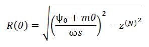
較佳地,該熱軌道自一中心C沿著一極座標R(θ) (如在圖12及圖13上繪示)繪製一線,該極座標藉由求解方程式(i)而獲得


為求解方程式(i),一旦獲得4變數函數

在一實施例中,該電聲裝置包括一堆疊,該堆疊連續包括該壓電部分、該主體及視情況堆疊在該主體上之至少一個基板。在另一實施例中,該電聲裝置包括一堆疊,該堆疊包括該主體及視情況堆疊在該主體上之至少一個基板。為了藉由求解方程組(i)至(viii)而界定該熱軌道之形狀,可實施下列方法,其包括連續步驟:
- 藉由一熟練工作人員熟知之標準方法計算該堆疊之各材料之慢度,即,該壓電部分及/或該主體及/或該(等)基板,
- 計算該等折射角

在方程式(i)中,角度ψ0 中之每一2π跳躍產生具有相同極性之一新的熱軌道之一線。相反極性具備一π跳躍。In equation (i), each 2π jump in the angle ψ 0 produces a line of a new hot orbit with the same polarity. The opposite polarity has a π jump.
在一實施例中,例如,該堆疊由一壓電部分及一主體構成,該主體比該壓電部分更厚,較佳地厚5倍,且由一各向同性材料製成,且該熱軌道自一中心C沿著一極座標R(θ)繪製一線,該方程式係
作為方程式組(i)至(vii)之一分析解獲得方程式(viii),其中


該熱電極較佳地包括完全圍繞該螺旋軸之一徑向內線圈,且界定一中心區;The hot electrode preferably includes a radially inner coil that completely surrounds the spiral axis and defines a central region;
該熱軌道較佳地沿著至少一個線圈,較佳地沿著至少5個線圈,甚至較佳地沿著15個線圈延伸。增加線圈之數目改良聚焦且增加捕獲力。The thermal track preferably extends along at least one coil, preferably along at least 5 coils, even preferably along 15 coils. Increasing the number of coils improves focusing and increases capturing power.
該熱電極可包括一熱電源端子,該熱軌道經電連接至該熱電源端子。The hot electrode may include a thermal power terminal, and the thermal rail is electrically connected to the thermal power terminal.
在一變體中,該接地電極可包括完全圍繞該螺旋軸之一徑向內線圈,且界定一中心區。In a variant, the ground electrode may include a radially inner coil completely surrounding the spiral axis and defining a central region.
該接地軌道可沿著至少一個線圈,較佳地沿著至少5個線圈,甚至較佳地沿著15個線圈延伸。The ground rail may extend along at least one coil, preferably along at least 5 coils, and even preferably along 15 coils.
較佳地,該接地軌道及該熱軌道兩者包括相同數目個線圈。Preferably, both the ground rail and the hot rail include the same number of coils.
該接地電極較佳地包括一接地電源端子,該接地軌道經電連接至該接地電源端子。The ground electrode preferably includes a ground power terminal, and the ground rail is electrically connected to the ground power terminal.
該接地電極可包括圍繞該螺旋軸螺旋之至少一個接地軌道。The ground electrode may include at least one ground rail spiraling around the spiral axis.
在一變體中,該接地軌道可提供於其中提供該熱軌道之該壓電部分之該面上。In a variant, the ground rail may be provided on the face of the piezoelectric portion in which the hot rail is provided.
該接地電極及/或該熱軌道可使用一電絕緣材料(較佳地呈一四分之一波長層之形式)塗佈。一四分之一波長層增強該聲波之傳輸。The ground electrode and/or the thermal track may be coated with an electrically insulating material (preferably in the form of a quarter-wavelength layer). A quarter-wavelength layer enhances the transmission of this sound wave.
較佳地,該電聲裝置包括複數個至少N個熱電極,其中N為至少2,較佳地至少4,且複數個熱電極之至少一者、較佳地所有熱電極包括圍繞該螺旋軸(X)螺旋之一熱軌道。特定言之,該接地軌道可提供於兩個相鄰熱軌道之間。換言之,該接地軌道及兩個相鄰熱軌道可交織。該N個熱軌道可彼此交織。Preferably, the electro-acoustic device includes a plurality of at least N hot electrodes, where N is at least 2, preferably at least 4, and at least one of the plurality of hot electrodes, preferably all of the hot electrodes include around the spiral axis (X) One of the hot tracks of the spiral. In particular, the grounding track may be provided between two adjacent hot tracks. In other words, the ground track and two adjacent hot tracks can be interwoven. The N hot tracks can be interwoven with each other.
在一些實施例中,該接地電極可包括至少M個接地軌道,其中M為至少2,較佳地至少4,較佳地M等於N,各接地軌道界定至少一個螺旋線圈,兩個相鄰接地軌道之兩個相鄰線圈之間的徑向距離自該螺旋軸減小。該M個接地軌道可彼此交織。In some embodiments, the ground electrode may include at least M ground rails, where M is at least 2, preferably at least 4, preferably M is equal to N, each ground rail defines at least one spiral coil, and two adjacent grounds The radial distance between two adjacent coils of the track decreases from the spiral axis. The M grounding tracks may be interwoven with each other.
在一些實施例中,該等接地軌道及該等熱軌道界定彼此交替之交織接地軌道及熱軌道之一圖案,且提供在該壓電部分之一個面上,且視情況提供在該壓電部分之相對面上。該等接地軌道可與該等熱軌道交織。In some embodiments, the ground rails and the hot rails define a pattern of interleaved ground rails and hot rails alternating with each other, and are provided on one face of the piezoelectric portion, and optionally provided on the piezoelectric portion On the opposite side. The ground rails can be interwoven with the hot rails.
在一些實施例中,該熱軌道之寬度可自中心徑向改變。該聚焦超音波渦旋之振幅可因此修改。注意,沿著一徑向方向,一徑向內線圈之寬度可大於一相鄰徑向外線圈之寬度。In some embodiments, the width of the hot track may change radially from the center. The amplitude of the focused ultrasound vortex can be modified accordingly. Note that along a radial direction, the width of a radially inner coil may be greater than the width of an adjacent radially outer coil.
較佳地,該電聲裝置可進一步包括一控制單元,該控制單元用於對該等熱電極供電且經組態用於控制由一熱電極及該接地電極構成之各電極對,使得該各對在該壓電部分中產生一體聲波(volume acoustic wave)(較佳地具有其範圍在100 KHz與10 GHz之間的基頻),藉由兩個相鄰電極對產生之該等體聲波之間的相移係2π/N。較佳地,該熱端子及接地端子經電連接至該控制單元。Preferably, the electroacoustic device may further include a control unit for powering the hot electrodes and configured to control each electrode pair composed of a hot electrode and the ground electrode, so that the For volume acoustic waves (preferably having a fundamental frequency in the range between 100 KHz and 10 GHz) generated in the piezoelectric part, the volume of the acoustic waves generated by two adjacent pairs of electrodes The phase shift system is 2π/N. Preferably, the thermal terminal and the ground terminal are electrically connected to the control unit.
在一些較佳實施例中,至少兩個熱電極各可包括界定至少一個螺旋線圈之一單一熱軌道,該兩個各自相鄰熱軌道之兩個相鄰線圈之間的徑向距離自該螺旋軸減小。In some preferred embodiments, each of the at least two thermal electrodes may include a single thermal track defining at least one spiral coil, and the radial distance between two adjacent coils of the two adjacent thermal tracks from the spiral The axis is reduced.
兩個相鄰熱軌道可提供於該壓電部分之相同面上。Two adjacent thermal tracks can be provided on the same face of the piezoelectric portion.
該熱電極及該接地電極較佳地藉由光微影沈積於該壓電部分上;特定言之,具有包括鉻或鈦之一材料之一層可在沈積該熱電極及該接地電極之前沈積於該壓電部分上,以便改良該壓電部分上之該等電極之黏附。The hot electrode and the ground electrode are preferably deposited on the piezoelectric portion by photolithography; in particular, a layer having a material including chromium or titanium can be deposited on the hot electrode and the ground electrode before being deposited In order to improve the adhesion of the electrodes on the piezoelectric part.
該熱電極及該接地電極可由一金屬材料(較佳地選自金、銀、鋁、鉻、鈦及其等混合物)製成;針對高於100 MHz之頻率下之應用,鋁係較佳的;當需要一良好導電率時,金及/或銀係較佳的。The hot electrode and the ground electrode can be made of a metal material (preferably selected from gold, silver, aluminum, chromium, titanium and their mixtures); for applications at frequencies above 100 MHz, aluminum is preferred ; When a good conductivity is required, gold and/or silver are preferred.
此外,該電聲裝置可包括提供於該主體上之一基底,其較佳地由一非壓電材料製成。該基底可至少部分由一非不透明(較佳地一透明材料)製成,尤其由玻璃製成。該基底可具有一板之形式,其具有範圍在10 µm與1 cm之間,較佳地範圍在100 µm與1 mm之間(例如等於150 µm)之一厚度。In addition, the electroacoustic device may include a substrate provided on the body, which is preferably made of a non-piezoelectric material. The substrate may be at least partially made of a non-opaque (preferably a transparent material), especially made of glass. The substrate may have the form of a plate having a thickness ranging between 10 µm and 1 cm, preferably ranging between 100 µm and 1 mm (for example equal to 150 µm).
該基底可為一顯微鏡之一物鏡之部分或可為經組態以固定至一顯微鏡之一物鏡之一裝置之部分。The substrate may be part of an objective lens of a microscope or may be part of a device configured to be fixed to an objective lens of a microscope.
該電聲裝置不限於包括一單一波換能器。特定言之,其可包括經組態用於在該主體中產生具有不同基諧波長之聚焦超音波渦旋之複數個波換能器。該電聲裝置可尤其包括定位於該波換能器之該中心區中之一視覺標記。The electroacoustic device is not limited to include a single wave transducer. In particular, it may include a plurality of wave transducers configured to generate focused ultrasound vortices with different fundamental harmonic lengths in the body. The electroacoustic device may especially include a visual mark positioned in the central zone of the wave transducer.
在一些實施例中,該電聲裝置可為圓盤形狀。注意,該基底可旋轉安裝於一樞軸上,且可經調適以圍繞一旋轉軸相對於該主體旋轉。此外,該電聲裝置可包括經組態用於使該基底相對於該波換能器位移(較佳地藉由沿著兩個橫軸之任一者之平移)之一機構。In some embodiments, the electroacoustic device may be disc-shaped. Note that the base can be rotatably mounted on a pivot, and can be adapted to rotate relative to the body about a rotation axis. In addition, the electroacoustic device may include a mechanism configured to displace the substrate relative to the wave transducer (preferably by translation along either of two transverse axes).
該電聲裝置進一步可包括第一波換能器及第二波換能器,在該裝置之一第一配置中之該第一波換能器之該中心之位置對應於在該裝置之一第二配置中之該第二波換能器之該中心之位置,該裝置可較佳地經組態使得藉由圍繞一樞軸之旋轉操作該第一配置至該第二配置之轉變。The electroacoustic device may further include a first wave transducer and a second wave transducer, the position of the center of the first wave transducer in one of the first configuration of the device corresponds to one of the devices The position of the center of the second wave transducer in the second configuration, the device may preferably be configured such that the transition from the first configuration to the second configuration is operated by rotation about a pivot.
該電聲裝置可包括用於將該等熱電極連接至一控制單元之一接觸電刷。該電聲裝置可包括第一波換能器及第二波換能器,在該裝置之各自第一配置及第二配置中,該等接觸電刷接觸該等各自第一波換能器及第二波換能器之該熱電極,該裝置較佳地經組態使得藉由圍繞一樞軸之旋轉操作該第一配置至該第二配置之轉變。The electroacoustic device may include a contact brush for connecting the isothermal electrode to a control unit. The electroacoustic device may include a first wave transducer and a second wave transducer. In respective first and second configurations of the device, the contact brushes contact the respective first wave transducer and The hot electrode of the second wave transducer, the device is preferably configured such that the transition from the first configuration to the second configuration is operated by rotation about a pivot.
根據一較佳第一特定實施例,該電聲裝置係使得該壓電部分不同於該主體,該主體經配置於該波換能器之一面上且與該波換能器聲學耦合。According to a preferred first specific embodiment, the electroacoustic device makes the piezoelectric portion different from the main body, which is arranged on a face of the wave transducer and is acoustically coupled with the wave transducer.
該主體較佳地至少部分由一非不透明且較佳地透明材料製成。較佳地,該主體由一非壓電材料製成。特定言之,該主體可由相對於一超音波之傳播之一各向同性材料製成。其可完全重疊該波換能器。The body is preferably at least partially made of a non-opaque and preferably transparent material. Preferably, the body is made of a non-piezoelectric material. In particular, the body can be made of an isotropic material with respect to the propagation of an ultrasonic wave. It can completely overlap the wave transducer.
較佳地,該主體包括選自一玻璃(尤其係硼矽玻璃)及一聚合物(尤其係一熱塑性塑膠,較佳地聚甲基丙烯酸甲酯(PMMA) )之一材料。更佳地,該主體包括玻璃。Preferably, the body includes a material selected from a glass (especially borosilicate glass) and a polymer (especially a thermoplastic, preferably polymethyl methacrylate (PMMA)). More preferably, the body includes glass.
主體厚度較佳地係該主體中之該聚焦渦旋之波長之至少1倍且至多5倍,尤其3倍。The thickness of the body is preferably at least 1 times and at most 5 times, especially 3 times the wavelength of the focused vortex in the body.
較佳地,該主體厚度之範圍在10 µm與1 cm之間。Preferably, the thickness of the body ranges between 10 µm and 1 cm.
該壓電部分及該主體可(例如)藉由一膠(尤其呈提供於該壓電部分與該主體之間的一層之形狀)聲學耦合。The piezoelectric portion and the main body may be acoustically coupled, for example, by a glue (especially in the shape of a layer provided between the piezoelectric portion and the main body).
至少一個熱電極可夾置於該壓電部分與該主體之間。At least one hot electrode may be sandwiched between the piezoelectric portion and the body.
至於該第一較佳實施例之該電聲部分之厚度,其較佳地小於或等於(2p+1)λ/2,其中λ係由一個電極對產生之該聲學體波之基諧波長,p係小於或等於5之一整數;較佳地,該電聲部分之厚度之範圍在100 nm與1 cm,較佳地在1 µm與100 µm之間。As for the thickness of the electroacoustic portion of the first preferred embodiment, it is preferably less than or equal to (2p+1)λ/2, where λ is the fundamental harmonic length of the acoustic bulk wave generated by an electrode pair , P is an integer less than or equal to 5; preferably, the thickness of the electroacoustic portion ranges between 100 nm and 1 cm, preferably between 1 µm and 100 µm.
此外,該波換能器可藉由一保護塗層(較佳地包括二氧化矽)覆蓋。In addition, the wave transducer can be covered with a protective coating (preferably including silicon dioxide).
在一變體中,該壓電部分較佳地包括一凹部,較佳地為提供於兩個相鄰熱電極之該等熱軌道之間的間隙之間之圍繞該螺旋軸Z螺旋之一溝槽。該凹部限制在該壓電部分中橫向傳播之一折聲波(diaphonic wave)之發展。In a variant, the piezoelectric portion preferably includes a recess, preferably a groove provided around the spiral axis Z spiral between the gaps between the thermal tracks of two adjacent thermal electrodes groove. The recess restricts the development of a diaphonic wave that propagates laterally in the piezoelectric portion.
至於該第一較佳實施例中之該熱電極及該接地電極之部署,該熱軌道可提供於該壓電部分與該主體之間。在一變體中,該裝置可包括複數個熱電極且該複數個熱電極之至少一半(尤其為全部)可提供於該壓電部分與該主體之間。As for the deployment of the hot electrode and the ground electrode in the first preferred embodiment, the hot track may be provided between the piezoelectric portion and the body. In a variant, the device may include a plurality of hot electrodes and at least half (particularly all) of the plurality of hot electrodes may be provided between the piezoelectric portion and the body.
兩個相鄰熱軌道可提供於該壓電部分之兩個相對面上。在一變體中,兩個相鄰熱軌道可提供於該壓電部分之相同面上。Two adjacent thermal tracks can be provided on two opposite faces of the piezoelectric portion. In a variant, two adjacent thermal tracks may be provided on the same face of the piezoelectric part.
至於該接地電極,其可包括圍繞該軸Z螺旋之一接地軌道,該接地軌道可提供於與其中提供該熱軌道之該面相對之該壓電部分之面上。較佳地,該接地軌道與其面向之該熱軌道疊置,且反之亦然。As for the ground electrode, it may include a ground track spiraling around the axis Z, and the ground track may be provided on the face of the piezoelectric portion opposite to the face in which the thermal track is provided. Preferably, the ground rail overlaps the hot rail it faces, and vice versa.
作為一替代例,該接地電極可包括一接地塗層,該接地塗層在該壓電部分之一面上方延伸且,較佳地完全與該複數個N個熱電極之各熱電極之該熱軌道疊置。一接地塗層可輕易以低成本沈積於該壓電部分上。As an alternative, the ground electrode may include a ground coating that extends over a face of the piezoelectric portion and, preferably, is completely in contact with the thermal track of each of the plurality of N thermal electrodes Stacked. A ground coating can be easily deposited on the piezoelectric portion at low cost.
若該接地電極包括複數個接地軌道,則該複數個接地軌道之各接地軌道可與該複數個熱電極之一各自熱電極之該熱軌道完全疊置,且反之亦然。該複數個接地軌道之各接地軌道可面向該複數個熱電極之一各自熱電極之一熱軌道,且反之亦然。If the ground electrode includes a plurality of ground rails, each ground rail of the plurality of ground rails may completely overlap with the thermal rail of each of the plurality of thermal electrodes, and vice versa. Each grounding rail of the plurality of grounding rails may face one of the thermal rails of each of the plurality of thermal electrodes, and vice versa.
安置於該壓電部分之一個面上之熱軌道之一圖案可疊置於安置於該相對面上之一圖案上,且反之亦然。A pattern of thermal tracks arranged on one face of the piezoelectric portion may be superimposed on a pattern arranged on the opposite face, and vice versa.
根據一較佳第二特定實施例,該電聲裝置可係使得該主體包括該壓電部分、該熱電極及該接地電極,較佳地由其等構成,該熱電極及該接地電極包括提供於該主體之一相同面上之各自熱軌道及接地軌道,該熱軌道及該接地軌道兩者圍繞該螺旋軸Z螺旋。較佳地,該熱軌道之一線圈相鄰於該熱電極之一線圈之間的徑向距離自該螺旋軸減小。According to a preferred second specific embodiment, the electroacoustic device may be such that the body includes the piezoelectric portion, the hot electrode and the ground electrode, preferably composed of the like, the hot electrode and the ground electrode include Respective hot orbits and grounding orbits on the same surface of one of the main bodies, both of which are spiral around the spiral axis Z. Preferably, the radial distance between a coil of the hot track adjacent to a coil of the hot electrode decreases from the spiral axis.
較佳地,根據該較佳第二實施例,該主體厚度之範圍係該主體中之該聚焦渦旋之波長之較佳地至少1倍且較佳地至多5倍,尤其等於3倍。較佳地,其範圍在10 µm與1 cm之間。該電聲裝置可包括一基底,該主體在一方面插置於該熱電極與該接地電極之間,且在另一方面插置於該熱電極與該基底之間。Preferably, according to the preferred second embodiment, the range of the thickness of the body is preferably at least 1 time and preferably at most 5 times the wavelength of the focusing vortex in the body, especially equal to 3 times. Preferably, the range is between 10 µm and 1 cm. The electroacoustic device may include a substrate, the body is interposed between the hot electrode and the ground electrode on the one hand, and between the hot electrode and the substrate on the other hand.
根據本發明之該電聲裝置可包括該流體介質,其較佳地與前體換能器重疊。特定言之,該流體介質可為一液體。The electroacoustic device according to the invention may comprise the fluid medium, which preferably overlaps the precursor transducer. In particular, the fluid medium may be a liquid.
該流體介質可包括一溶劑或甚至由一溶劑構成,其中至少一個物件可嵌入該溶劑中。例如,該溶劑係水。例如,該物件選自一顆粒、一液滴、一氣泡、不同於該流體介質之另一流體介質、一藥物膠囊及一生物樣本,例如,一細胞、一微生物、一胞器,該物件嵌入該流體介質中。The fluid medium may include or even consist of a solvent, at least one of which may be embedded in the solvent. For example, the solvent is water. For example, the object is selected from a particle, a droplet, a bubble, another fluid medium different from the fluid medium, a drug capsule, and a biological sample, for example, a cell, a microorganism, an organelle, the object is embedded The fluid medium.
在一實施例中,該電聲裝置可包括該波換能器所附接至之一支撐件。該支撐件可包括經調適以藉由一使用者之一手或一機器人臂握持之一把手。例如,該電聲裝置呈一筆之形式。在一變體中,該支撐件包括一載台及一基底,該載台經調適以沿著相對於該基底之至少一個(例如,兩個,較佳地三個)較佳地垂直方向移動。該載台之該位移可藉由一馬達或手動致動。In an embodiment, the electroacoustic device may include a support to which the wave transducer is attached. The support may include a handle adapted to be held by a user's hand or a robot arm. For example, the electroacoustic device is in the form of a pen. In a variant, the support comprises a stage and a base, the stage is adapted to move in at least one (eg, two, preferably three) preferably perpendicular directions relative to the base . The displacement of the stage can be actuated by a motor or manually.
此外,本發明係關於一種用於操縱一流體,較佳地液體介質或至少一個物件之方法,該物件較佳地選自一顆粒、一液滴、一氣泡、不同於該流體介質之另一流體介質、一藥物膠囊及一生物樣本,例如,一細胞、一微生物、一胞器,該物件嵌入該流體介質中,該方法包括連續步驟,其等包括: - 使用根據本發明之該電聲裝置產生一聚焦超音波渦旋, - 定位該流體介質,使得該聚焦超音波渦旋之焦點軌跡經提供於該流體介質之體積中,諸如以產生該物件經遞交至之一聲學阱或一聲學流,及 - 視情況而言,透過該電聲裝置之波換能器相對於該流體介質之位移操縱該物件。In addition, the present invention relates to a method for manipulating a fluid, preferably a liquid medium or at least one object, the object is preferably selected from a particle, a droplet, a bubble, another one different from the fluid medium A fluid medium, a medicine capsule, and a biological sample, for example, a cell, a microorganism, an organelle, the object is embedded in the fluid medium, the method includes continuous steps, and the like include: -Use the electroacoustic device according to the invention to generate a focused ultrasound vortex, -Positioning the fluid medium so that the focal trajectory of the focused ultrasound vortex is provided in the volume of the fluid medium, such as to produce an acoustic trap or an acoustic flow of the object submitted to, and -Depending on the situation, the object is manipulated by the displacement of the wave transducer of the electroacoustic device relative to the fluid medium.
最後,本發明亦係關於使用本發明之該電聲裝置產生一聚焦超音波渦旋。該聚焦超音波渦旋可為各向同性或各向異性的。特定言之,其可為球形的。Finally, the invention also relates to the use of the electroacoustic device of the invention to generate a focused ultrasound vortex. The focused ultrasound vortex may be isotropic or anisotropic. In particular, it may be spherical.
例如,透過方程式(ix)定義在一「各向同性介質」中傳播之一「球形渦旋」:


一「超音」波具有範圍在1 MHz與10000 MHz之間的一頻率。A "supersonic" wave has a frequency ranging between 1 MHz and 10000 MHz.
一「徑向」方向垂直於該螺旋軸。A "radial" direction is perpendicular to the spiral axis.
一「徑向」平面包括該螺旋軸及一個徑向方向兩者。A "radial" plane includes both the spiral axis and a radial direction.
一「橫向」平面垂直於該螺旋軸。A "transverse" plane is perpendicular to the spiral axis.
一「徑向內」部分沿著一徑向方向比一「徑向外」部分更靠近該螺旋軸。A "radially inner" portion is closer to the spiral axis along a radial direction than a "radially outer" portion.
一螺旋之一「線圈」係圍繞該螺旋軸以至少360°之一角度有角度地延伸之一螺旋之一部分。A "coil" of a helix is a portion of a helix that extends angularly around the helix axis at an angle of at least 360°.
一部分之「厚度」沿著平行於該螺旋軸之一方向量測。A part of the "thickness" is measured along a direction parallel to the spiral axis.
兩個線圈之間的「徑向間距(radial step)」對應於在兩者皆定位於兩個相鄰線圈之一中間寬度處之兩個點之間量測之徑向距離。The "radial step" between the two coils corresponds to the radial distance measured between two points where both are positioned at the intermediate width of one of the two adjacent coils.
在可能提供於一壓電部分之兩個面上之複數個軌道中,當觀察到沿著該螺旋軸投射該壓電部分之一橫向橫截面時,「相鄰於」一第一軌道之一第二軌道係距該第一軌道之徑向距離最小之軌道。同樣的情況適用於一螺旋或一電極之一線圈。根據此定義,提供於該壓電部分之一面上之一第一軌道可鄰近於提供於該壓電部分之相對面上之一第二軌道。In a plurality of orbits that may be provided on two faces of a piezoelectric portion, when it is observed to project a transverse cross-section of the piezoelectric portion along the spiral axis, one is "adjacent" to one of the first orbits The second track is the track with the smallest radial distance from the first track. The same applies to a coil of one spiral or one electrode. According to this definition, a first track provided on one face of the piezoelectric portion may be adjacent to a second track provided on the opposite face of the piezoelectric portion.
圖1至圖5繪示電聲裝置5之一第一實施例。1 to 5 illustrate a first embodiment of the
根據圖1至圖5之電聲裝置包括具有呈等於120 µm之厚度es
之一板之形狀之一壓電部分7,其呈現一上面及一下面。其由以35°進行Y切割之一LiBNO3
製成。The electroacoustic device according to FIGS. 1 to 5 includes a
電聲裝置亦包括由硼矽玻璃製成之一主體10 (在圖5上表示),其具有6.5 mm之一厚度eb 。主體藉由一耦合介質12 (例如,Norland Product之光學黏合劑NOA61)聲學耦合至壓電部分。The electroacoustic device also includes a body 10 (shown in FIG. 5) made of borosilicate glass, which has a thickness e b of 6.5 mm. The main body is acoustically coupled to the piezoelectric portion through a coupling medium 12 (for example, Norland Product's optical adhesive NOA61).
兩個熱第一電極15及第二電極17經提供於上面20上,且各包括用於將熱電極連接至一控制單元24之一接觸電刷22a至22b,該控制單元24提供電力至第一電極及第二電極。第一熱電極、第二熱電極分別包括分別圍繞垂直於上面之一共同螺旋軸Z螺旋之一第一熱軌道25、第二熱軌道27。第一熱軌道、第二熱軌道分別包括若干線圈,第一熱軌道及第二熱軌道之各者之內線圈環繞界定於上面上之一中心區30。在未表示之一變體中,電聲裝置可包括超過2個,尤其為4個熱電極,其等之全部包括圍繞螺旋軸Z螺旋之熱軌道。Two hot
如其可在圖2及圖4上觀察到,第一熱軌道及第二熱軌道螺旋係使得分別在第一熱軌道、第二熱軌道之兩個相鄰線圈之間的徑向間距∆r自中心減小。例如,徑向內相鄰線圈與徑向外相鄰線圈之間的徑向間距自136 µm減小至115 µm。As can be observed in FIGS. 2 and 4, the spiral system of the first and second thermal orbits makes the radial distance Δr between two adjacent coils of the first and second thermal orbits from The center decreases. For example, the radial spacing between radially inner adjacent coils and radially outer adjacent coils has been reduced from 136 µm to 115 µm.
電聲裝置包括一接地電極35,至於圖1至圖4上繪示之實施例,接地電極35由在與上面相對之下面37上方部分延伸之一接地塗層36構成。第一電極及第二電極、接地電極及壓電部分界定一波換能器41。接地電極經電連接至接地40。如在圖3上繪示,其中提供於上面上之熱電極經繪製為虛線圖案,接地塗層完全覆蓋第一熱軌道及第二熱軌道。在一方面,第一軌道及接地塗層,且在另一方面第二軌道及接地塗層界定第一電極對42及第二電極對44,其等在經供電時分別產生使壓電部分變形之第一體超音波W1
及第二體超音波W2
。特定言之,控制單元經調適用於將電力遞送至第一電極及第二電極,使得第一體超音波及第二體超音波之間的相移等於π。The electroacoustic device includes a
此外,如在圖5中繪示,主體10提供於上面20之頂部上,使得第一熱電極15及第二熱電極17夾置於壓電部分7與主體之間。In addition, as shown in FIG. 5, the
電聲裝置包括提供於與面向波換能器之一個面相對之面上之一基底。基底係由具有150 µm之厚度ea 之硼矽玻璃製成之一板。基底可在橫向於螺旋Z之至少兩個方向上移動。具有少於10 µm之厚度之一介面液體經提供於基底與主體之間。The electroacoustic device includes a substrate provided on a face opposite to the face facing the wave transducer. The substrate is a plate made of borosilicate glass with a thickness e a of 150 µm. The substrate can move in at least two directions transverse to the spiral Z. An interface liquid having a thickness of less than 10 µm is provided between the substrate and the main body.
例如由PDMS製成之一消音器50經提供於基底上,該基底界定含有一流體介質58 (較佳地一液體介質)之一腔室55。一物件60嵌入流體介質中。A
當對熱電極供電時,藉由實質上沿著平行於螺旋軸之一方向在壓電部分中傳播之第一體超音波W1 及第二體超音波W2 使波換能器變形。When power is supplied to the hot electrode, the wave transducer is deformed by the first bulk ultrasonic wave W 1 and the second bulk ultrasonic wave W 2 propagating in the piezoelectric portion substantially along a direction parallel to the spiral axis.
波換能器將該等體超音波傳輸至主體之體積,其中該等體超音波界定一聚焦超音波渦旋FV,其之焦點軌跡(其中聲學強度係最低的)定位於腔室中。藉由使基底相對於主體位移,可使物件接近焦點軌跡。其接著可沿著螺旋軸操縱且尤其截留。The wave transducer transmits the body ultrasound to the volume of the body, where the body ultrasound defines a focused ultrasound vortex FV, whose focal trajectory (where the acoustic intensity is the lowest) is located in the chamber. By displacing the base relative to the main body, the object can be brought close to the focal track. It can then be manipulated along the screw axis and is particularly trapped.
圖6中繪示之電聲裝置與圖1上繪示之電聲裝置不同之處在於形成於壓電部分中的一凹部65,該凹部65徑向提供於第一熱電極15與第二熱電極17之間,且由圍繞軸Z螺旋之一溝槽構成。螺旋溝槽包括至少一個線圈,在當前情況中為4個線圈。如繪示,溝槽之一線圈之徑向寬度∆c
可自螺旋軸Z減小。在一變體中,其可為恆定的。凹部限制基板中之折聲橫向體或表面聲波之傳播。The electroacoustic device illustrated in FIG. 6 differs from the electroacoustic device illustrated in FIG. 1 in that a
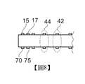
圖7及圖8上繪示之電聲裝置與圖1上繪示之電聲裝置之不同之處在於以下事實:接地電極包括兩個第一接地軌道70及第二接地軌道75而非接地塗層,且其等兩者連接至接地40。The electroacoustic device depicted in FIGS. 7 and 8 differs from the electroacoustic device depicted in FIG. 1 due to the fact that the ground electrode includes two first ground rails 70 and second ground rails 75 instead of ground coating Layer, and both of them are connected to the
接地軌道經提供於壓電部分之下面37上,與其上提供第一熱電極及第二熱電極之面相對。The ground rail is provided on the
第一接地軌道、第二接地軌道分別完全疊置於第一熱軌道、第二熱軌道上,且反之亦然。其等界定第一電極對42及第二電極對44。The first ground rail and the second ground rail are completely stacked on the first hot rail and the second hot rail, respectively, and vice versa. They etc. define the
圖9上繪示之電聲裝置與圖8上繪示之電聲裝置之不同之處在於下列特徵。The electroacoustic device shown in FIG. 9 is different from the electroacoustic device shown in FIG. 8 in the following features.
在上面上,替代圖1之裝置之第二熱電極,提供一接地軌道78,其具有相對於螺旋Z之一形狀及位置,其等相同於圖8之裝置之第二熱電極。In the above, instead of the second hot electrode of the device of FIG. 1, a
在下面上,替代圖1之裝置之第二接地電極,提供一熱軌道79,其具有相對於螺旋Z之一形狀及位置,其等相同於圖8之裝置之第二熱電極。In the following, instead of the second ground electrode of the device of FIG. 1, a
圖10及圖11繪示本發明之一第二實施例。根據第二實施例之電聲裝置與圖1上繪示之實施例之不同之處在於以下事實:其包括一主體10,該主體10由一壓電部分7構成,該壓電部分7由具有150微米厚度之LiNbO3
Y切口製成,該主體10具有一上面及與該上面相對之一下面;且該不同之處在於以下事實:在主體之相同面上(在當前情況中在下面上)提供一接地電極80及一熱電極85。該接地電極80及該熱電極85包括圍繞一螺旋軸Z螺旋之各自接地軌道及熱軌道。10 and 11 illustrate a second embodiment of the invention. The electroacoustic device according to the second embodiment differs from the embodiment illustrated in FIG. 1 in the fact that it includes a
熱螺旋軌道及接地螺旋軌道界定其上安置其等之面上之各自軌道之線圈之一交織圖案。The hot spiral track and the ground spiral track define one of the interweave patterns of the coils on which the respective tracks are placed on their equal surfaces.
此外,電聲裝置包括提供於與面向波換能器之一個面相對之面上之一基底。基底係由具有150 µm之厚度ea 之硼矽玻璃製成之一板。基底可在橫向於螺旋軸Z之至少兩個方向上移動。具有少於10 µm之厚度之一介面膠經提供於基底與主體之間。In addition, the electroacoustic device includes a substrate provided on a face opposite to the face facing the wave transducer. The substrate is a plate made of borosilicate glass with a thickness e a of 150 µm. The substrate can move in at least two directions transverse to the spiral axis Z. An interface glue with a thickness of less than 10 µm is provided between the substrate and the body.
例如由PDMS製成之一消音器50經提供於基底上,該基底界定含有一流體介質58 (較佳地一液體)之一腔室55。一物件60嵌入流體介質中。A
熱軌道及接地軌道經保形使得其等引發之兩個相鄰線圈之間的壓電部分之局部變形在藉由控制單元對熱軌道供電時,干擾界定在主體中傳播且聚焦於含有流體介質之腔室中之一聚焦超音波渦旋。藉由使基底相對於主體位移,可操縱該物件。The hot track and the ground track are shaped so that they cause local deformation of the piezoelectric part between two adjacent coils. When the hot track is powered by the control unit, the interference is defined to propagate in the main body and focus on the fluid-containing medium One of the chambers focuses on the ultrasonic vortex. The object can be manipulated by displacing the base relative to the main body.
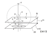
圖12繪示用於界定諸如(例如)由方程式(x)定義之一球形渦旋之一笛卡爾座標系之位置,該焦點軌跡由點2指代且截斷其上提供電極之平面(由n=0指代),該平面(例如)係壓電部分之面20。FIG. 12 illustrates the position of a Cartesian coordinate system such as, for example, a spherical vortex defined by equation (x). The focal trajectory is indicated by
圖13旨在繪示方程式(i)至(vii)之求解,在該情況中,渦旋FV在作為壓電部分之主體中沿著軸Z自熱軌道朝向焦點軌跡2傳播一距離z(N)
。渦旋FV包括3D線,沿著該等3D線相位恆定,稱為等相線。例如,沿著一等相線99,渦旋之相位在點100a至100c處係相同的。沿著接合焦點軌跡2及點100a至100c之線117,等相線99之投影係一平面線,其藉由在其中提供軌道之表面上自中心C表達之參數R(θ)設定。換言之,聚焦超音波渦旋之相位至其中必須提供熱軌道之平面上之交叉產生熱軌道之繪製。此係(例如)藉由方程式組(i)至(viii)數學表達。藉由形成繪製該線R(θ)之至少一個熱軌道,可產生聚焦在焦點2處之一超音波渦旋。圖13之實例對應於方程式組(i)至(viii)之求解之一特定情況,其中電聲裝置包括作為壓電部分之一單一主體。熟習此項技術者將明確瞭解,上文繪示之方法可應用至本發明之任何其他變體,例如,在電聲裝置包括一壓電部分、不同於壓電部分之一主體及視情況提供於主體頂部上之其他基板之情況中。13 is intended to illustrate the solution of equations (i) to (vii), in this case, the vortex FV propagates a distance z (N ) . The vortex FV includes 3D lines along which the phase is constant, and is called an isophase line. For example, along an isophase line 99, the phases of the vortices are the same at
圖14展示根據本發明之電聲裝置5之另一實施例。電聲裝置5具有可藉由一使用者握持之一筆128之大體形狀。其包括沿著一延長軸延伸,且一波換能器41所附接至之一支撐件130。波換能器經提供於支撐件之一末端處。波換能器包括一主體10,該主體10由一壓電部分7構成。以如已在圖4中繪示之一方式,第一熱電極15及第二熱電極17經提供於主體之一面上且一接地電極36經提供於主體之另一部分上。電聲裝置進一步包括提供在其中提供第一熱電極及第二熱電極之面之頂部上及該等熱電極之頂部上之一四分之一波長層135。四分之一波長濾波器由一電隔離材料製成以防止如下文將瞭解之任何電分流。在一變體中,接地電極及第一熱電極及第二熱電極可皆分別提供在面向支撐件之壓電部分之面上。FIG. 14 shows another embodiment of the
電聲裝置可用於以以下方式操縱一物件。The electroacoustic device can be used to manipulate an object in the following manner.
使用一流體介質120 (較佳地一液體介質)(其中嵌入一物件122)來充填包括一開口111且界定一腔室112之一容器110。電聲裝置由一使用者處置,使得波換能器浸沒於液體中。A fluid medium 120 (preferably a liquid medium) in which an object 122 is embedded is used to fill a
當藉由一發電機(未表示)施加一電壓至電聲裝置時,產生使壓電部分變形之第一體超音波W1
及第二體超音波W2
。波換能器直接在流體介質中傳輸該等體超音波W1
及W2
,其中其等界定一聚焦超音波渦旋FV,該焦點軌跡(即,其中聲學強度係最低的)定位於腔室中。藉由使電聲裝置5相對於容器110位移,可使物件122接近焦點軌跡。接著可以3D操縱該物件122。When a voltage is applied to the electroacoustic device by a generator (not shown), a first body ultrasonic wave W 1 and a second body ultrasonic wave W 2 that deform the piezoelectric portion are generated. The wave transducer transmits the bulk ultrasonic waves W 1 and W 2 directly in the fluid medium, where they define a focused ultrasonic vortex FV, the focal trajectory (ie, where the acoustic intensity is the lowest) is located in the chamber in. By displacing the
圖15繪示根據本發明之一電聲裝置5之另一實施例。FIG. 15 illustrates another embodiment of an
圖15之電聲裝置與圖1之電聲裝置之不同之處在於其包括一單一熱電極125且接地電極130與熱電極配置於壓電部分7之相同面上。在當前情況中,其等經提供於壓電部分之上面20上。The electroacoustic device of FIG. 15 differs from the electroacoustic device of FIG. 1 in that it includes a single
接地電極及熱電極各包括待連接至一控制單元140之一接觸電刷135a至135b。控制單元提供不同電位至接地電極及熱電極。接地電極(例如)經連接至控制單元之一接地插座,該電位經定義為一參考,如係接地40。The ground electrode and the hot electrode each include one of the contact brushes 135a to 135b to be connected to a
特定言之,熱電極及接地電極之電位可相對於彼此異相達等於π之一相位。In particular, the potentials of the hot electrode and the ground electrode may be out of phase with respect to each other by a phase equal to π.
熱電極及接地電極分別包括一熱軌道145及一接地軌道150,其等圍繞垂直於上面之一共同軸Z螺旋。熱軌道、接地軌道分別包括若干線圈,其等之各者之內線圈環繞界定於上面上之一中心區230。The hot electrode and the ground electrode include a
此外,熱軌道及接地軌道彼此交織。In addition, the hot track and the ground track are interwoven with each other.
如其可在圖16上觀察到,接地軌道及熱軌道係使得分別在接地軌道、熱軌道之兩個相鄰線圈240a至240b之間的徑向間距Δr’自中心徑向減小。As it can be observed in FIG. 16, the ground rail and the hot rail are such that the radial distance Δr' between the two
當控制單元提供一電力至熱電極時,接地電極及熱電極產生使壓電部分變形之體超音波。超音波可經傳輸至主體之體積以依圖5中描繪之方式界定一聚焦超音波渦旋。When the control unit supplies an electric power to the hot electrode, the ground electrode and the hot electrode generate a body ultrasonic wave that deforms the piezoelectric portion. Ultrasound can be transmitted to the volume of the body to define a focused ultrasound vortex in the manner depicted in FIG. 5.
如本描述通篇可見,根據本發明之電聲裝置改良操縱嵌入於一流體介質中之一物件之效率。其進一步改良在操縱物件群間之一特定物件時之選擇性。As can be seen throughout this description, the electroacoustic device according to the present invention improves the efficiency of handling an object embedded in a fluid medium. It further improves selectivity when manipulating a specific object among object groups.
當然,本發明不限於本描述中詳述之特定實施例。Of course, the invention is not limited to the specific embodiments detailed in this description.
2:焦點軌跡
5:電聲裝置
7:壓電部分
10:主體
12:耦合介質
15:第一電極
17:第二電極
20:上面
22a:接觸電刷
22b:接觸電刷
24:控制單元
25:第一熱軌道
27:第二熱軌道
30:中心區
35:接地電極
36:接地塗層
37:下面
40:接地
41:波換能器
42:第一電極對
44:第二電極對
50:消音器
55:腔室
58:流體介質
60:物件
65:凹部
70:第一接地軌道
75:第二接地軌道
78:接地軌道
79:熱軌道
80:接地電極
85:熱電極
100a:點
100b:點
100c:點
110:容器
111:開口
112:腔室
117:線
120:流體介質
122:物件
125:單一熱電極
128:筆
130:支撐件
135:四分之一波長層
135a:接觸電刷
135b:接觸電刷
140:控制單元
145:熱軌道
150:接地軌道
230:中心區
240a:線圈
240b:線圈
C:中心
ea:厚度
eb:厚度
es:厚度
FV:聚焦超音波渦旋
R(θ):參數
W1:第一體超音波
W2:第二體超音波
x:軸
y:軸
Z:螺旋軸
z:軸
z(N):距離
可參考本發明之例示性及非限制性實施例且藉由查閱附圖而自以下實施方式的閱讀更佳理解本發明,在圖中:The invention can be better understood with reference to the illustrative and non-limiting examples of the present invention and by reading the following embodiments by referring to the drawings, in the drawings:
圖1自一透視圖繪示根據本發明之一第一實施例之一電聲裝置;FIG. 1 illustrates an electro-acoustic device according to a first embodiment of the present invention from a perspective view;
圖2及圖3分別繪示沿著圖1之電聲裝置之波換能器之一面及其相對面之螺旋軸之視圖,2 and 3 respectively show views along the spiral axis of one face and the opposite face of the wave transducer of the electroacoustic device of FIG. 1,
圖4繪示圖1之電聲裝置之一軸向橫截面之一側視圖,4 is a side view of an axial cross section of the electroacoustic device of FIG. 1,
圖5繪示經實施用於操縱一物件之圖1之電聲裝置之一軸向橫截面之一側視圖,5 shows a side view of an axial cross-section of the electroacoustic device of FIG. 1 implemented for manipulating an object,
圖6繪示圖1之電聲裝置之一變體之一軸向橫截面之一側視圖,6 illustrates a side view of an axial cross-section of a variation of the electroacoustic device of FIG. 1,
圖7及圖8分別繪示圖1之電聲裝置之一變體之一軸向橫截面之一前視圖及一側視圖,7 and 8 respectively show a front view and a side view of an axial cross section of a variant of the electroacoustic device of FIG. 1,
圖9繪示圖1之裝置之另一變體之一軸向橫截面之一側視圖,9 illustrates a side view of an axial cross-section of another variation of the device of FIG. 1,
圖10自一透視圖繪示根據本發明之一第二實施例之一電聲裝置,10 is a perspective view showing an electro-acoustic device according to a second embodiment of the present invention,
圖11繪示用於操縱一物件之圖10之電聲裝置之一軸向橫截面之一側視圖,11 is a side view of an axial cross section of the electroacoustic device of FIG. 10 for manipulating an object,
圖12繪示用於表達方程式(i)至(x)之參考點之定義,FIG. 12 illustrates the definition of reference points used to express equations (i) to (x),
圖13繪示經實施以界定用於產生一聚焦超音波之熱電極之特定形狀之一方法,13 shows a method implemented to define a specific shape of a thermode used to generate a focused ultrasound,
圖14繪示根據本發明之電聲裝置之另一實例之一軸向橫截面之一側視圖,14 is a side view of an axial cross section of another example of an electroacoustic device according to the present invention,
圖15自一透視圖繪示根據本發明之電聲裝置之另一實例,及15 shows another example of an electroacoustic device according to the present invention from a perspective view, and
圖16繪示圖15之電聲裝置之一軸向橫截面之一側視圖。16 is a side view of an axial cross section of the electroacoustic device of FIG. 15.
在圖式中,為清晰起見,未始終遵從不同元件之各自比例及大小。In the drawings, for the sake of clarity, the respective proportions and sizes of different components are not always adhered to.
5:電聲裝置 5: Electroacoustic device
7:壓電部分 7: Piezo part
15:第一電極 15: First electrode
17:第二電極 17: Second electrode
20:上面 20: above
22a:接觸電刷 22a: contact brush
22b:接觸電刷 22b: contact brush
24:控制單元 24: control unit
25:第一熱軌道 25: The first hot track
27:第二熱軌道 27: The second hot track
30:中心區 30: Central area
37:下面 37: below
41:波換能器 41: wave transducer
Z:螺旋軸 Z: spiral axis
es:厚度 e s : thickness
Claims (23)


Applications Claiming Priority (2)
| Application Number | Priority Date | Filing Date | Title |
|---|---|---|---|
| EP17198204.4 | 2017-10-25 | ||
| EP17198204 | 2017-10-25 |
Publications (1)
| Publication Number | Publication Date |
|---|---|
| TW202017652A true TW202017652A (en) | 2020-05-16 |
Family
ID=60327046
Family Applications (1)
| Application Number | Title | Priority Date | Filing Date |
|---|---|---|---|
| TW107137706A TW202017652A (en) | 2017-10-25 | 2018-10-25 | Acoustic tweezers |
Country Status (8)
| Country | Link |
|---|---|
| US (1) | US11534761B2 (en) |
| EP (1) | EP3700669B1 (en) |
| JP (1) | JP7390662B2 (en) |
| CN (1) | CN111511471A (en) |
| CA (1) | CA3079358A1 (en) |
| ES (1) | ES2903370T3 (en) |
| TW (1) | TW202017652A (en) |
| WO (1) | WO2019081521A1 (en) |
Families Citing this family (18)
| Publication number | Priority date | Publication date | Assignee | Title |
|---|---|---|---|---|
| US10704021B2 (en) | 2012-03-15 | 2020-07-07 | Flodesign Sonics, Inc. | Acoustic perfusion devices |
| WO2015105955A1 (en) | 2014-01-08 | 2015-07-16 | Flodesign Sonics, Inc. | Acoustophoresis device with dual acoustophoretic chamber |
| US11708572B2 (en) | 2015-04-29 | 2023-07-25 | Flodesign Sonics, Inc. | Acoustic cell separation techniques and processes |
| US11377651B2 (en) | 2016-10-19 | 2022-07-05 | Flodesign Sonics, Inc. | Cell therapy processes utilizing acoustophoresis |
| ES2841528T3 (en) * | 2016-03-15 | 2021-07-08 | Centre Nat Rech Scient | Acoustic Tweezers |
| KR102439221B1 (en) | 2017-12-14 | 2022-09-01 | 프로디자인 소닉스, 인크. | Acoustic transducer actuators and controllers |
| US20230219086A1 (en) * | 2019-06-13 | 2023-07-13 | Savelife Biotechnology Co. Limited | Method and device for cell or microvesicle isolation |
| CN110475188A (en) * | 2019-07-30 | 2019-11-19 | 吕舒晗 | A kind of flexible piezoelectric energy converter and system |
| CN110420826A (en) * | 2019-07-30 | 2019-11-08 | 吕舒晗 | It is a kind of for generating the PZT (piezoelectric transducer) and its system of sound vortex wave beam |
| WO2021051386A1 (en) * | 2019-09-20 | 2021-03-25 | 深圳先进技术研究院 | Ultrasonic cleaning device, and cleaning method and application thereof |
| US12533671B2 (en) | 2019-12-18 | 2026-01-27 | Université de Lille | Electroacoustic device for manipulating objects in a liquid |
| CN111069008A (en) * | 2019-12-30 | 2020-04-28 | 西北工业大学 | Method and system for generating vortex sound field by using transducer array |
| WO2023065063A1 (en) * | 2021-10-18 | 2023-04-27 | Fudan University | Apparatus and system for particle manipulation |
| US12303900B2 (en) | 2021-10-18 | 2025-05-20 | Fudan University | Photoacoustic tweezers |
| CN114160070A (en) * | 2021-12-02 | 2022-03-11 | 深圳先进技术研究院 | Control method, acoustic tweezers device and microscopic equipment applying acoustic tweezers device |
| CN114842823B (en) * | 2022-05-19 | 2024-07-12 | 西安交通大学 | A codable ultrasonic tweezers system and implementation method thereof |
| CN117358563B (en) * | 2023-11-09 | 2025-11-07 | 重庆大学 | Closed vortex sound beam spanner based on multichannel least square method |
| CN118433618A (en) * | 2024-07-03 | 2024-08-02 | 荣耀终端有限公司 | MEMS speaker core and module, preparation method, and electronic device |
Family Cites Families (17)
| Publication number | Priority date | Publication date | Assignee | Title |
|---|---|---|---|---|
| US4453242A (en) | 1982-07-13 | 1984-06-05 | Rca Corporation | Surface acoustic wave cutterhead for disc recording having a circular transducer |
| JP3489509B2 (en) * | 1999-02-22 | 2004-01-19 | 株式会社村田製作所 | Electroacoustic transducer |
| US6359367B1 (en) * | 1999-12-06 | 2002-03-19 | Acuson Corporation | Micromachined ultrasonic spiral arrays for medical diagnostic imaging |
| WO2003093494A2 (en) | 2002-05-04 | 2003-11-13 | Aviva Biosciences Corporation | Apparatus including ion transport detecting structures and methods of use |
| WO2004021044A1 (en) * | 2002-08-29 | 2004-03-11 | Eagle Ultrasound As | An ultrasound transceiver system for remote operation through a minimal number of connecting wires |
| US7377169B2 (en) * | 2004-04-09 | 2008-05-27 | Shell Oil Company | Apparatus and methods for acoustically determining fluid properties while sampling |
| WO2008056286A1 (en) * | 2006-11-08 | 2008-05-15 | Nxp B.V. | Acoustic device and method of manufacturing the same |
| US7878063B1 (en) | 2007-07-24 | 2011-02-01 | University Of South Florida | Simultaneous sample manipulation and sensing using surface acoustic waves |
| JP4760931B2 (en) | 2009-03-02 | 2011-08-31 | 株式会社デンソー | Surface acoustic wave device |
| GB0914762D0 (en) | 2009-08-24 | 2009-09-30 | Univ Glasgow | Fluidics apparatus and fluidics substrate |
| WO2011033277A2 (en) | 2009-09-21 | 2011-03-24 | University Of Dundee | Apparatus and method for the manipulation of objects using ultrasound |
| JP2015512766A (en) | 2012-01-31 | 2015-04-30 | ザ・ペン・ステート・リサーチ・ファンデーション | Microfluidic manipulation and particle classification using variable stationary surface acoustic waves |
| WO2014178782A1 (en) | 2013-04-30 | 2014-11-06 | Acousort Ab | Microsystem and method to focus cells or particles using acoustophoresis |
| EP2898352B1 (en) * | 2013-12-17 | 2018-06-06 | Halliburton Energy Services, Inc. | Tunable acoustic transmitter for downhole use |
| WO2015134831A1 (en) | 2014-03-07 | 2015-09-11 | The Penn State Research Foundation | Acoustic control apparatus, process, and fabrication thereof |
| ES2841528T3 (en) | 2016-03-15 | 2021-07-08 | Centre Nat Rech Scient | Acoustic Tweezers |
| EP3463660A1 (en) * | 2016-05-24 | 2019-04-10 | Centre National De La Recherche Scientifique | Acoustic tweezers |
-
2018
- 2018-10-23 CA CA3079358A patent/CA3079358A1/en active Pending
- 2018-10-23 EP EP18792928.6A patent/EP3700669B1/en active Active
- 2018-10-23 CN CN201880070240.5A patent/CN111511471A/en active Pending
- 2018-10-23 ES ES18792928T patent/ES2903370T3/en active Active
- 2018-10-23 JP JP2020522039A patent/JP7390662B2/en active Active
- 2018-10-23 WO PCT/EP2018/079053 patent/WO2019081521A1/en not_active Ceased
- 2018-10-23 US US16/757,160 patent/US11534761B2/en active Active
- 2018-10-25 TW TW107137706A patent/TW202017652A/en unknown
Also Published As
| Publication number | Publication date |
|---|---|
| ES2903370T3 (en) | 2022-04-01 |
| US11534761B2 (en) | 2022-12-27 |
| WO2019081521A1 (en) | 2019-05-02 |
| CA3079358A1 (en) | 2019-05-02 |
| EP3700669A1 (en) | 2020-09-02 |
| CN111511471A (en) | 2020-08-07 |
| JP7390662B2 (en) | 2023-12-04 |
| US20200338593A1 (en) | 2020-10-29 |
| EP3700669B1 (en) | 2021-11-03 |
| JP2021500221A (en) | 2021-01-07 |
Similar Documents
| Publication | Publication Date | Title |
|---|---|---|
| TW202017652A (en) | Acoustic tweezers | |
| US12179192B2 (en) | Acoustic tweezers | |
| US20200316586A1 (en) | Acoustic tweezers | |
| Zhu et al. | Micro-particle manipulation by single beam acoustic tweezers based on hydrothermal PZT thick film | |
| JP7809256B2 (en) | Electrical audio equipment | |
| CN111659478B (en) | Ultrasonic surface standing wave micro-fluidic chip for micro-particle separation and application | |
| Liu et al. | An ultrasonic tweezer with multiple manipulation functions based on the double-parabolic-reflector wave-guided high-power ultrasonic transducer | |
| CN114100707B (en) | A device for trapping micro-nano particles | |
| Vuille-dit-Bille et al. | On-chip particle levitation and micromanipulation using bulk acoustic waves | |
| Mikhaylov | The development of acoustofluidic devices using printed circuit boards | |
| Zhang | Designs of Surface Acoustic Waves for Micro/Nano-scale Particles/Fluid Manipulation | |
| Sakar et al. | Three-dimensional on-chip micromanipulation using bulk acoustic waves | |
| Despont | Three-dimensional on-chip micromanipulation using bulk acoustic waves | |
| CN115957564A (en) | Fluid device | |
| Matar | Folding a focalized acoustical vortex on a flat holographic transducer: Miniaturized selective acoustical tweezers | |
| Liu | Ultrasonic trapping of small particles | |
| Tang et al. | Analysis of complex spiral vortex field in nano particle concentration | |
| Brodie | Hybrid Optical and Acoustic Trapping |