TW202011507A - Gas transmission structure of wafer carrier can increase usage convenience and efficiency without additionally connecting devices and structures - Google Patents
Gas transmission structure of wafer carrier can increase usage convenience and efficiency without additionally connecting devices and structures Download PDFInfo
- Publication number
- TW202011507A TW202011507A TW107132450A TW107132450A TW202011507A TW 202011507 A TW202011507 A TW 202011507A TW 107132450 A TW107132450 A TW 107132450A TW 107132450 A TW107132450 A TW 107132450A TW 202011507 A TW202011507 A TW 202011507A
- Authority
- TW
- Taiwan
- Prior art keywords
- wafer carrier
- gas
- component
- carrier
- rotating
- Prior art date
Links
- 230000005540 biological transmission Effects 0.000 title claims abstract description 17
- 239000007789 gas Substances 0.000 abstract description 38
- 239000011261 inert gas Substances 0.000 abstract description 14
- 238000007599 discharging Methods 0.000 abstract 3
- 235000012431 wafers Nutrition 0.000 description 59
- 238000010586 diagram Methods 0.000 description 10
- 230000007246 mechanism Effects 0.000 description 10
- 230000003647 oxidation Effects 0.000 description 4
- 238000007254 oxidation reaction Methods 0.000 description 4
- 239000000969 carrier Substances 0.000 description 3
- 238000000034 method Methods 0.000 description 3
- 230000007812 deficiency Effects 0.000 description 2
- 238000009795 derivation Methods 0.000 description 2
- 230000004048 modification Effects 0.000 description 2
- 238000012986 modification Methods 0.000 description 2
- 239000012159 carrier gas Substances 0.000 description 1
- 230000003749 cleanliness Effects 0.000 description 1
- 230000000694 effects Effects 0.000 description 1
- 238000000605 extraction Methods 0.000 description 1
- 239000004065 semiconductor Substances 0.000 description 1
- 239000000126 substance Substances 0.000 description 1
- 239000013589 supplement Substances 0.000 description 1
Images




Landscapes
- Container, Conveyance, Adherence, Positioning, Of Wafer (AREA)
Abstract
Description
本發明為提供一種晶圓載具之氣體傳輸結構,尤指一種可防止晶圓載具內晶圓氧化並且增加使用上方便性的晶圓載具之氣體傳輸結構。 The present invention is to provide a gas transmission structure of a wafer carrier, in particular to a gas transmission structure of a wafer carrier which can prevent oxidation of wafers in the wafer carrier and increase convenience in use.
按,一般來說,半導體的晶圓大多都會利用晶圓載具(FOUP)來裝載,藉此來增加運送時的方便性以及維持整潔,且一般晶圓載具內部都會導入一些惰性氣體,藉此來降低保存時氧化的可能性,而要將晶圓載具中的晶圓取出作業時,都會將晶圓載具放置於一承載機構(load port)上,並把蓋體開啟以配合機台將晶圓取出。 Generally speaking, most of the semiconductor wafers are loaded with wafer carriers (FOUP) to increase the convenience of transportation and maintain cleanliness. In general, some inert gases are introduced into the wafer carriers. The possibility of oxidation during storage is reduced, and when the wafers in the wafer carrier are to be taken out, the wafer carrier is placed on a load port and the lid is opened to match the wafer with the machine take out.
但一般的承載機構(load port)都僅有承載或放置晶圓載具的功能,其功能性相當的單一。因此當更換完畢晶圓並將蓋體蓋上時,還需另外的機構來補充惰性氣體,相當麻煩且不便,而且放置時還要對準開啟蓋體機構的位置,使用上的效率也較低。 However, general load ports only have the function of carrying or placing wafer carriers, and their functionality is quite single. Therefore, when the wafer is replaced and the lid is covered, another mechanism is needed to supplement the inert gas, which is quite cumbersome and inconvenient, and it must be aligned with the position of the lid opening mechanism when placed, which is also inefficient in use .
是以,要如何解決上述習用之問題與缺失,即為本發明之申請人與從事此行業之相關廠商所亟欲研究改善之方向所在。 Therefore, how to solve the above-mentioned conventional problems and deficiencies is the direction that the applicant of the present invention and related manufacturers engaged in this industry are eager to study and improve.
故,本發明之發明人有鑑於上述缺失,乃蒐集相關資料,經由多方評估及考量,並以從事於此行業累積之多年經驗,經由不斷試作及修改,始設計出此種能將惰性氣體導入晶圓載具中,同時能旋轉晶圓載具以提升方便性及效率的晶圓載具之氣體傳輸結構的發明專利者。 Therefore, in view of the above-mentioned deficiencies, the inventor of the present invention has collected relevant data, evaluated and considered through multiple parties, and based on years of experience accumulated in this industry, through continuous trial work and modification, he designed this kind of inert gas introduction In the wafer carrier, the inventor of the invention of the gas transmission structure of the wafer carrier that can rotate the wafer carrier at the same time to improve convenience and efficiency.
本發明之主要目的在於:利用進氣組件及出氣組件將氣體導入或導出晶圓載具內,並且經由旋轉組件來旋轉承載座,藉此增加使用上的方便性及效率。 The main purpose of the present invention is to use the air inlet component and the air outlet component to introduce or export gas into the wafer carrier, and rotate the carrier through the rotating component, thereby increasing the convenience and efficiency in use.
為達成上述目的,本發明之主要結構包括:一架體、一設於架體上的轉動組件、一設於轉動組件上的承載座、一設於架體上的進出氣裝置以及、至少一連接該進出氣裝置上的進氣組件、與至少一連接於進出氣裝置上的出氣組件,而進氣組件及出氣組件背離進出氣裝置的一端處會連接於承載座上。 To achieve the above object, the main structure of the present invention includes: a frame body, a rotating component provided on the frame body, a bearing seat provided on the rotating component, an air inlet and outlet device provided on the frame body, and at least one The air inlet assembly connected to the air inlet and outlet device and at least one air outlet assembly connected to the air inlet and outlet device, and the end of the air inlet assembly and the air outlet assembly facing away from the air inlet and outlet device are connected to the bearing seat.
藉由上述之結構,使用者可將晶圓載具放置於承載座上,並經由轉動組件來轉動承載座,藉此來轉動晶圓載具的位置,以對應相配合的機構,例如開啟蓋體的機構、或是取出晶圓的機構,皆能增加使用上的方便性,而晶圓載具放置於承載座上時,進氣組件及出氣組件會連接於晶圓載具上,並經由進出氣裝置將氣體導入或導出晶圓載具中。故當晶圓載具裝載完成,或是內部的惰性氣體不足時,就可利用出氣組件將內部的氣體導出,同時利用進氣組件將惰性氣體導入晶圓載具中,藉此來降低內部晶圓產生氧化的機會,並且可直接於承載座上進行,不需另外連接裝置及結構,故能增加使用上的方便性及效率。 With the above structure, the user can place the wafer carrier on the carrier, and rotate the carrier through the rotating component, thereby rotating the position of the wafer carrier to correspond to a matching mechanism, such as opening the lid The mechanism, or the mechanism for taking out the wafer, can increase the convenience of use. When the wafer carrier is placed on the carrier, the air inlet component and the air outlet component will be connected to the wafer carrier, and the air inlet and outlet device will be The gas is imported or exported into the wafer carrier. Therefore, when the wafer carrier is loaded, or the internal inert gas is insufficient, the gas can be used to export the internal gas, and the gas inlet can be used to introduce the inert gas into the wafer carrier, thereby reducing the internal wafer generation The opportunity of oxidation can be carried out directly on the carrier, without additional connection devices and structures, so it can increase the convenience and efficiency in use.
藉由上述技術,可針對習用的承載機構功能性單一及使用上不方便的問題點加以突破,達到上述優點之實用進步性。 With the above-mentioned technology, it is possible to break through the problem of the single function of the conventional bearing mechanism and the inconvenience in use, to achieve the practical progress of the above advantages.
1、1a、1b‧‧‧架體 1. 1a, 1b ‧‧‧ frame
11b‧‧‧移動組件 11b‧‧‧Mobile component
2、2a‧‧‧轉動組件 2. 2a‧‧‧rotating component
21‧‧‧轉動座 21‧‧‧Rotating seat
22‧‧‧旋轉動力件 22‧‧‧rotating power parts
3、3a‧‧‧承載座 3. 3a‧‧‧Bearing seat
31‧‧‧定位部 31‧‧‧Positioning Department
4‧‧‧進出氣裝置 4‧‧‧Inlet and outlet device
5‧‧‧進氣組件 5‧‧‧Intake components
51‧‧‧進氣連接件 51‧‧‧ Intake connector
52‧‧‧進氣管件 52‧‧‧Intake pipe fittings
6‧‧‧出氣組件 6‧‧‧ Outlet components
61‧‧‧出氣連接件 61‧‧‧ Outlet connector
62‧‧‧出氣管件 62‧‧‧Outlet fittings
7、7a‧‧‧晶圓載具 7, 7a‧‧‧wafer carrier
8a‧‧‧吸取組件 8a‧‧‧Suction components
81a‧‧‧吸取件 81a‧‧‧Suction
82a‧‧‧移動支架 82a‧‧‧Mobile bracket
9a‧‧‧水平移動組件 9a‧‧‧horizontal moving component
91a‧‧‧水平動力件 91a‧‧‧horizontal power parts
92a‧‧‧滑軌 92a‧‧‧slide
93a‧‧‧動力承載件 93a‧‧‧Power bearing
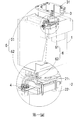
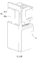
第一圖 係為本發明較佳實施例之立體透視圖。 The first figure is a perspective perspective view of a preferred embodiment of the present invention.
第二圖 係為本發明較佳實施例之放置示意圖。 The second figure is a schematic view of the preferred embodiment of the invention.
第三圖 係為本發明較佳實施例之氣體導入示意圖(一)。 The third figure is a schematic diagram (1) of gas introduction according to a preferred embodiment of the present invention.
第四圖 係為本發明較佳實施例之氣體導入示意圖(二)。 The fourth figure is a schematic diagram (2) of gas introduction according to a preferred embodiment of the present invention.
第五圖 係為本發明較佳實施例之氣體導出示意圖(一)。 The fifth figure is a schematic diagram (1) of the gas derivation according to the preferred embodiment of the present invention.
第六圖 係為本發明較佳實施例之氣體導出示意圖(二)。 The sixth figure is a schematic diagram (2) of the gas derivation according to the preferred embodiment of the present invention.
第七圖 係為本發明較佳實施例之轉動示意圖。 The seventh figure is a schematic view of the rotation of the preferred embodiment of the present invention.
第八圖 係為本發明再一較佳實施例之立體透視圖。 Figure 8 is a perspective view of yet another preferred embodiment of the present invention.
第九圖 係為本發明再一較佳實施例之另一角度立體圖。 The ninth figure is another perspective view of another preferred embodiment of the present invention.
第十圖 係為本發明再一較佳實施例之移動示意圖。 Fig. 10 is a schematic diagram of movement of still another preferred embodiment of the present invention.
第十一圖 係為本發明再一較佳實施例之吸取示意圖。 Figure 11 is a schematic drawing of another preferred embodiment of the present invention.
第十二圖 係為本發明再一較佳實施例之取用示意圖。 Figure 12 is a schematic diagram of another preferred embodiment of the present invention.
第十三圖 係為本發明另一較佳實施例之移動示意圖。 Figure 13 is a schematic diagram of movement of another preferred embodiment of the present invention.
為達成上述目的及功效,本發明所採用之技術手段及構造,茲繪圖就本發明較佳實施例詳加說明其特徵與功能如下,俾利完全了解。 In order to achieve the above objectives and effects, the technical means and structure adopted by the present invention, the drawings and details of the preferred embodiments of the present invention are described in detail below. Their features and functions are as follows, so that they fully understand.
請參閱第一圖及第二圖所示,係為本發明較佳實施例之立體透視圖及放置示意圖,由圖中可清楚看出本發明係包括:一架體1、一轉動組件2、一承載座3、一進出氣裝置4、複數進氣組件5、及複數出氣組件6,其中,轉動組件2會設於架體1上,並且轉動組件2會包含有一轉動座21及一旋轉動力件22,旋轉動力件22設於架體1上,而轉動座21連接於旋轉動力件22上,以經由旋轉動力件22轉動,而旋轉動力件22可利用馬達、氣動、油壓等方式來轉動,本實施例以氣動的方式做舉例,而承載座3會設於轉動座21上,並且承載座3上會具有複數的定位部31,進出氣裝置4設於架體1上,而進氣組件5包含有一進氣連接件51及一進氣管件52,進氣連接件51會設於承載座3上,進氣管件52之兩端處會分別連接進氣連接件51及進出氣裝置4,出氣組件6則包含有一出氣連接件61及一出氣管件62,出氣連接件61會設於承載座3上,而出氣管件62之兩端處會分別連接出氣連接件61及進出氣裝置4。 Please refer to the first and second figures, which are perspective perspective views and placement schematic diagrams of preferred embodiments of the present invention. It can be clearly seen from the figures that the present invention includes: a
藉由上述之說明,已可了解本技術之結構,而依據這個結構之對應配合,即可經由轉動組件2轉動承載座3及晶圓載具7,並且將惰性氣體導入晶圓載具7中以達到更加方便及更加具有效率的優勢,而詳細之解說將於下述說明。 Through the above description, the structure of the technology can be understood, and according to the corresponding cooperation of this structure, the
請同時配合參閱第一圖至第七圖所示,係為本發明較佳實施例之立體透視圖至轉動示意圖,藉由上述構件組構時,由圖中可清楚看出,使用者可將晶圓載具7放置於承載座3上,並經由定位部31讓晶圓載具7固定及定位的更加穩固。 Please also refer to the first figure to the seventh figure, which is a perspective perspective view to a rotation schematic view of the preferred embodiment of the present invention. When the above components are configured, it can be clearly seen from the figure that the user can The
當晶圓載具7放置於承載座3上時,進氣連接件51及出氣連接件61即會與晶圓載具7的內部相連通,故當使用者取放完畢晶圓或是晶圓載具7內的 惰性氣體不足時,就可由進出氣裝置4連接複數的供氣來源,供氣來源並不設限,藉此將供氣來源與進氣組件5及出氣組件6相連接,並控制進出氣裝置4來將惰性氣體導入進氣組件5或是將出氣組件6中的氣體抽出,控制方式可利用氣閥、開關等方式控制,其亦不設限,藉此將惰性氣體經由進氣管件52及進氣連接件51導入晶圓載具7中,同時利用抽取出氣組件6中的氣體,以通過出氣管件62及出氣連接件61將晶圓載具7內部的其餘氣體抽出,藉此讓晶圓載具7內充滿惰性氣體,由於惰性氣體較不容易產生化學變化,故可降低晶圓載具7內的晶圓氧化的機會,如此一來不需另外連接機構,即可將惰性氣體導入晶圓載具7內,同時將內部的氣體抽出,故能增加使用上的方便性及效率。 When the
使用者還能將氣體導入旋轉動力件22中,以轉動轉動座21及承載座3(旋轉動力件22為一般習用的氣壓缸,故不再贅述其結構及作動),藉此來轉動晶圓載具7以對應各種的機構,例如開啟晶圓載具7蓋體的裝置、或取出晶圓的裝置,故放置時不再需要特別對準對應的機構,可增加使用上的方便性。 The user can also introduce gas into the
再請同時配合參閱第八圖至第十二圖所示,係為本發明再一較佳實施例之立體透視圖至取用示意圖,由圖中可清楚看出,本實施例與上述實施例為大同小異,由於正常的承載機構(load port)都會具有開啟晶圓載具7a的結構,故於本實施例中,架體1a上會設有一吸取組件8a及一位於轉動組件2a及架體1a之間的水平移動組件9a,而吸取組件8a包含有一吸取件81a及一移動支架82a,吸取件81a設於承載座3a的一側處,以吸取晶圓載具7a的蓋體,而移動支架82a的一端處設於架體1a上,另一端處連接於吸取件81a上,藉此來移動吸取件81a,而移動支架82a之移動方式可為氣動、馬達、油壓等,其並不設限,水平移動組件9a則包含有一水平動力件91a、二滑軌92a、及一動力承載件93a,滑軌92a設於架體1a上,動力承載件93a則滑動設置於滑軌92a上,並且動力承載件93a會連接轉動組件2a,而水平動力件91a設於架體1a上並位於滑軌92a及動力承載件93a的一側處,並連接動力承載件93a,以讓動力承載件93a經由水平動力件91a給予的動力於滑軌92a上滑動,而水平動力件91a可為馬達、氣動、或油壓等方式,其並不設限。 Please also refer to the eighth to twelfth figures, which are perspective views to schematic diagrams of another preferred embodiment of the present invention. It can be clearly seen from the figure that this embodiment and the above-mentioned embodiments For the same, the normal load port will have the structure to open the
當使用者將晶圓載具7a放置於承載座3a上後,可經由轉動組件2a將 晶圓載具7a對準吸取組件8a,並控制水平動力件91a將動力傳遞至動力承載件93a上,藉此將動力承載件93a經由滑軌92a往吸取組件8a的方向移動,同時帶動承載座3a及晶圓載具7a靠近吸取組件8a,其控制方式可經由控制器控制或是將氣體導入水平動力件91a中,其控制方式亦不設限,當晶圓載具7a碰觸到吸取件81a時,吸取件81a即會吸取晶圓載具7a的蓋體,並經由移動支架82a將蓋體移開,讓使用者取放晶圓載具7a中的晶圓,如此就可讓使用者更加方便的取用晶圓載具7a內部的晶圓,可再次提高使用上的方便性。 After the user places the
再請同時配合參閱第十三圖所示,係為本發明又一較佳實施例之移動示意圖,由圖中可清楚看出,本實施例與上述實施例為大同小異,僅於架體1b上設有一移動組件11b,能讓使用者經由移動組件11b推動架體1b,來增加使用上的方便性。 Please also refer to the thirteenth figure at the same time, which is a schematic diagram of the movement of another preferred embodiment of the present invention. It can be clearly seen from the figure that this embodiment is similar to the above embodiment, only on the
惟,以上所述僅為本發明之較佳實施例而已,非因此即侷限本發明之專利範圍,故舉凡運用本發明說明書及圖式內容所為之簡易修飾及等效結構變化,均應同理包含於本發明之專利範圍內,合予陳明。 However, the above is only the preferred embodiment of the present invention, and it does not limit the patent scope of the present invention. Therefore, all the simple modifications and equivalent structural changes caused by the description and drawings of the present invention should be the same. It is included in the patent scope of the present invention and is conjoined with Chen Ming.
是以,本發明之晶圓載具之氣體傳輸結構可改善習用之技術關鍵在於: Therefore, the key to improving the conventional technology of the wafer carrier gas transmission structure of the present invention is:
一、經由轉動組件2來轉動承載座3及晶圓載具7,以配合各種對應機構,來增加使用上的方便性。 1. Rotating the
二、經由進出氣裝置4、進氣組件5、及出氣組件6將惰性氣體導入晶圓載具7內,以增加使用上的效率。 2. Inert gas is introduced into the
三、利用水平移動組件9a配合吸取組件8a,來再次提升使用上的效率。 3. The horizontal moving
綜上所述,本發明之晶圓載具之氣體傳輸結構於使用時,為確實能達到其功效及目的,故本發明誠為一實用性優異之發明,為符合發明專利之申請要件,爰依法提出申請,盼 審委早日賜准本發明,以保障申請人之辛苦創作,倘若 鈞局審委有任何稽疑,請不吝來函指示,申請人定當竭力配合,實感德便。 In summary, when the gas transmission structure of the wafer carrier of the present invention is used, in order to indeed achieve its efficacy and purpose, the present invention is an invention with excellent practicability, which is in accordance with the application requirements of the invention patent. After submitting the application, I hope that the review committee will grant the invention as soon as possible to protect the applicant's hard work. If there is any doubt in the review committee of the Jun Bureau, please send me a letter and give instructions. The applicant will try his best to cooperate and feel virtuous.
1‧‧‧架體 1‧‧‧frame
2‧‧‧轉動組件 2‧‧‧Rotating components
21‧‧‧轉動座 21‧‧‧Rotating seat
22‧‧‧旋轉動力件 22‧‧‧rotating power parts
3‧‧‧承載座 3‧‧‧Carrier
31‧‧‧定位部 31‧‧‧Positioning Department
4‧‧‧進出氣裝置 4‧‧‧Inlet and outlet device
5‧‧‧進氣組件 5‧‧‧Intake components
51‧‧‧進氣連接件 51‧‧‧ Intake connector
52‧‧‧進氣管件 52‧‧‧Intake pipe fittings
6‧‧‧出氣組件 6‧‧‧ Outlet components
61‧‧‧出氣連接件 61‧‧‧ Outlet connector
62‧‧‧出氣管件 62‧‧‧Outlet fittings
Claims (10)
Priority Applications (1)
| Application Number | Priority Date | Filing Date | Title |
|---|---|---|---|
| TW107132450A TW202011507A (en) | 2018-09-14 | 2018-09-14 | Gas transmission structure of wafer carrier can increase usage convenience and efficiency without additionally connecting devices and structures |
Applications Claiming Priority (1)
| Application Number | Priority Date | Filing Date | Title |
|---|---|---|---|
| TW107132450A TW202011507A (en) | 2018-09-14 | 2018-09-14 | Gas transmission structure of wafer carrier can increase usage convenience and efficiency without additionally connecting devices and structures |
Publications (1)
| Publication Number | Publication Date |
|---|---|
| TW202011507A true TW202011507A (en) | 2020-03-16 |
Family
ID=70766742
Family Applications (1)
| Application Number | Title | Priority Date | Filing Date |
|---|---|---|---|
| TW107132450A TW202011507A (en) | 2018-09-14 | 2018-09-14 | Gas transmission structure of wafer carrier can increase usage convenience and efficiency without additionally connecting devices and structures |
Country Status (1)
| Country | Link |
|---|---|
| TW (1) | TW202011507A (en) |
Cited By (1)
| Publication number | Priority date | Publication date | Assignee | Title |
|---|---|---|---|---|
| TWI742826B (en) * | 2020-08-28 | 2021-10-11 | 樂華科技股份有限公司 | Wafer carrier vacuum moving device and method |
-
2018
- 2018-09-14 TW TW107132450A patent/TW202011507A/en unknown
Cited By (1)
| Publication number | Priority date | Publication date | Assignee | Title |
|---|---|---|---|---|
| TWI742826B (en) * | 2020-08-28 | 2021-10-11 | 樂華科技股份有限公司 | Wafer carrier vacuum moving device and method |
Similar Documents
| Publication | Publication Date | Title |
|---|---|---|
| CN104339362B (en) | Magnetic vacuum inhales lamps structure and the feeding device being made up of it | |
| CN1057403C (en) | Integrated circuit assembling and disassembling device and its assembling and disassembling head | |
| CN104528381B (en) | The transfer integrating device of single-phase electric energy meter and reuse carton | |
| TW202011507A (en) | Gas transmission structure of wafer carrier can increase usage convenience and efficiency without additionally connecting devices and structures | |
| CN107571060B (en) | Synchronous adjustable adsorption module of many adsorption sites | |
| CN206084509U (en) | Intelligence phone lens loop component machinin's fixed tool | |
| CN107068604A (en) | Wafer cassette conveys Load System | |
| TWM505455U (en) | Film removal device and film tearing machine thereof | |
| TWM575605U (en) | Gas transmission structure of wafer carrier | |
| CN216541714U (en) | Automatic material taking and elbow inserting device | |
| CN112811160B (en) | Battery cell transferring device and system | |
| CN208954957U (en) | gas transmission structure of wafer carrier | |
| CN211388843U (en) | A clamp suction cup negative pressure box and its deputy clamp | |
| WO2016132651A1 (en) | Carrier transport device and carrier transport method | |
| CN102366912A (en) | Vacuum workbench composed of air valves special for deburring machine and negative pressure control method | |
| CN118404473A (en) | Metal product processing equipment | |
| CN109760875A (en) | A kind of method that packaging is put in wiring board automation | |
| TWI742826B (en) | Wafer carrier vacuum moving device and method | |
| CN210535644U (en) | Automatic wafer conversion machine platform | |
| CN215248108U (en) | Simple vacuum discharging device | |
| CN201120610Y (en) | Robot device with integrated fetching, delivering, aligning functions | |
| CN205996656U (en) | Mobile phone aluminum frame transportation manipulator | |
| CN207402498U (en) | One kind adsorbs some positions synchronously adjustable adsorption module more | |
| CN204195770U (en) | The take out device that magnetic vacuum is inhaled lamps structure and is made up of it | |
| TWM605707U (en) | Wafer carrier having vacuum moving apparatus |