RU2656001C1 - Rear bicycle gear selector - Google Patents
Rear bicycle gear selector Download PDFInfo
- Publication number
- RU2656001C1 RU2656001C1 RU2017115619A RU2017115619A RU2656001C1 RU 2656001 C1 RU2656001 C1 RU 2656001C1 RU 2017115619 A RU2017115619 A RU 2017115619A RU 2017115619 A RU2017115619 A RU 2017115619A RU 2656001 C1 RU2656001 C1 RU 2656001C1
- Authority
- RU
- Russia
- Prior art keywords
- protrusion
- rear bicycle
- cylindrical
- bicycle
- switch housing
- Prior art date
Links
- 125000006850 spacer group Chemical group 0.000 claims abstract description 5
- 238000000034 method Methods 0.000 claims description 2
- 230000003313 weakening effect Effects 0.000 claims description 2
- 239000000126 substance Substances 0.000 abstract 1
- 230000008878 coupling Effects 0.000 description 2
- 238000010168 coupling process Methods 0.000 description 2
- 238000005859 coupling reaction Methods 0.000 description 2
- 230000002860 competitive effect Effects 0.000 description 1
- 230000001351 cycling effect Effects 0.000 description 1
Images


Classifications
-
- B—PERFORMING OPERATIONS; TRANSPORTING
- B62—LAND VEHICLES FOR TRAVELLING OTHERWISE THAN ON RAILS
- B62M—RIDER PROPULSION OF WHEELED VEHICLES OR SLEDGES; POWERED PROPULSION OF SLEDGES OR SINGLE-TRACK CYCLES; TRANSMISSIONS SPECIALLY ADAPTED FOR SUCH VEHICLES
- B62M9/00—Transmissions characterised by use of an endless chain, belt, or the like
- B62M9/04—Transmissions characterised by use of an endless chain, belt, or the like of changeable ratio
- B62M9/06—Transmissions characterised by use of an endless chain, belt, or the like of changeable ratio using a single chain, belt, or the like
- B62M9/10—Transmissions characterised by use of an endless chain, belt, or the like of changeable ratio using a single chain, belt, or the like involving different-sized wheels, e.g. rear sprocket chain wheels selectively engaged by the chain, belt, or the like
- B62M9/12—Transmissions characterised by use of an endless chain, belt, or the like of changeable ratio using a single chain, belt, or the like involving different-sized wheels, e.g. rear sprocket chain wheels selectively engaged by the chain, belt, or the like the chain, belt, or the like being laterally shiftable, e.g. using a rear derailleur
- B62M9/121—Rear derailleurs
- B62M9/125—Mounting the derailleur on the frame
Landscapes
- Engineering & Computer Science (AREA)
- Chemical & Material Sciences (AREA)
- Combustion & Propulsion (AREA)
- Transportation (AREA)
- Mechanical Engineering (AREA)
- Transmission Devices (AREA)
Abstract
Description
Изобретение относится к области спортивной техники и может быть использовано в велосипедных соревнованиях.The invention relates to the field of sports equipment and can be used in cycling competitions.
При езде на гоночном велосипеде в соревновательных условиях, основным требованием к конструктивным элементам его заднего переключателя передач является простота конструкции, надежность и четкость переключения передач и уменьшение его аэродинамического сопротивления.When riding a racing bike in a competitive environment, the main requirement for the structural elements of its rear gear shifter is simplicity of design, reliability and clarity of gear shifting and a decrease in its aerodynamic drag.
Известен задний переключатель передач велосипеда, раскрытый в патенте US 5961409, содержащий кронштейн, закрепленный на наконечнике задней вилки рамы велосипеда; рычаги шарнирного параллелограмма; корпус переключателя с роликами, закрепленными между пластинами.A rear bicycle gearshift is disclosed in US Pat. No. 5,961,409, comprising a bracket mounted on a tip of a rear fork of a bicycle frame; articulated parallelogram levers; switch housing with rollers fixed between the plates.
Однако такая конструкция заднего переключателя передач велосипеда сложна, имеет много деталей, а перегибы приводного троса при смене передач уменьшают четкость и надежность переключения.However, this design of the bicycle’s rear gear shifter is complex, has many details, and the excesses of the drive cable when changing gears reduce the clarity and reliability of the shift.
Известен задний переключатель передач велосипеда, раскрытый в патенте US 6350212 B1, содержащий кронштейн с установленной в нем пружиной кручения и поворотным винтом, закрепленным на наконечнике задней вилки рамы велосипеда; рычаги шарнирного параллелограмма, на внешнем рычаге которого закреплен гайкой через фигурную шайбу приводной трос, направляющий боуден которого установлен через регулировочный винт в кронштейн.A rear bicycle gearshift is disclosed in US Pat. No. 6,350,212 B1, comprising a bracket with a torsion spring installed therein and a rotary screw fixed to the tip of the rear fork of the bicycle frame; levers of a hinged parallelogram, on the external lever of which is fixed with a nut through a figured washer, a drive cable, the guide bowden of which is installed through the adjustment screw in the bracket.
Однако такая конструкция заднего переключателя передач велосипеда сложна и не может обеспечить четкость и надежность переключения передач из-за небольшого расстояния от упора боудена до места крепления приводного троса, что вызывает перегибы приводного троса, а изгиб направляющего боудена перед его упором в регулировочный винт составляет 180°, что вызывает повышенный износ внутренней пластмассовой оболочки боудена и заедание приводного троса. Следует отметить сложность конструкции такого переключателя передач, а увеличенные габаритные размеры и размещение его в районе крепления заднего колеса повышает его аэродинамическое сопротивление. Кроме того, для точного переноса приводной цепи от одной ведомой шестеренки к другой требуется точный расчет увеличения-уменьшения длины приводного троса для каждого переключения передач.However, this design of the bicycle’s rear gear selector is complex and cannot provide clarity and reliability of gear shifting due to the small distance from the Bowden stop to the attachment point of the drive cable, which causes the drive cable to be bent, and the bowden guide bend is 180 ° before it stops against the adjusting screw , which causes increased wear of the inner plastic shell of the Bowden and jamming of the drive cable. It should be noted the complexity of the design of such a gear shifter, and the increased overall dimensions and its placement in the area of the rear wheel mounting increase its aerodynamic drag. In addition, for the exact transfer of the drive chain from one driven gear to another, an accurate calculation of the increase-decrease in the length of the drive cable for each gear shift is required.
Предлагаемым изобретением решается задача повышения эксплуатационных характеристик заднего переключателя передач велосипеда за счет упрощения конструкции переключателя, уменьшения габаритных размеров и приближения его к плоскости заднего колеса велосипеда, полного исключения механических деформаций и перегибов приводного троса при повороте рычагов шарнирного параллелограмма, устранения заеданий приводного троса в направляющем боудене при переключении передач и автоматическая остановка вращения поворотной пластины при аварийном сбросе приводной цепи с ведущей шестеренки.The present invention solves the problem of increasing the operational characteristics of the rear gear shift of a bicycle by simplifying the design of the switch, reducing its overall dimensions and bringing it closer to the plane of the rear wheel of the bicycle, completely eliminating mechanical deformations and kinks of the drive cable while turning the levers of the articulated parallelogram, eliminating jamming of the drive cable in the guide bowden when shifting gears and automatically stopping rotation of the turntable during emergency th reset the drive chain from the pinion gear.
Согласно изобретению поставленная задача решается тем, что кронштейн установлен непосредственно на нижнем правом пере задней вилки рамы велосипеда перед его ведомыми шестеренками; на внутреннем рычаге шарнирного параллелограмма имеется выступ с отверстием, который по отношению к оси его крепления к кронштейну расположен перпендикулярно к плоскости, проходящей через оси его крепления к кронштейну и корпусу переключателя, что позволяет при натяжении или ослаблении приводного троса на одинаковые величины в продольном (по отношению к велосипеду) направлении перемещать направляющий ролик на одинаковые расстояния в поперечном (по отношению к велосипеду) направлении, выставляя его каждый раз напротив одной из ведомых шестеренок кассеты заднего колеса велосипеда; через отверстие на выступе внутреннего рычага шарнирного параллелограмма установлена поворотная втулка, в которой выполнены сквозное отверстие для свободного прохода приводного троса и цилиндрическая выточка - для размещения в ней ограничительной бобышки приводного троса; поворотная втулка имеет вырез, в который установлен выступ внутреннего рычага шарнирного параллелограмма и закреплен через отверстие запорным цилиндрическим шплинтом, обеспечивающим свободное угловое перемещение поворотной втулки относительно внутреннего рычага шарнирного параллелограмма при переключении передач; упор направляющего боудена в цилиндрическую выточку регулировочного винта расположен на выступе кареточного узла рамы велосипеда, а приводной трос на всем своем протяжении от кареточного узла рамы велосипеда до места своего крепления в поворотной втулке представляет собой прямую линию; возвратная пружина переключения передач состоит из двух рабочих цилиндрических частей пружины кручения, соединенных между собой одной общей нерабочей частью пружины и установленных на двух осях крепления внутреннего рычага шарнирного параллелограмма с упором своих двух свободных нерабочих частей пружины на оси крепления внешнего рычага шарнирного параллелограмма; место крепления внутреннего рычага шарнирного параллелограмма к корпусу переключателя расположено перед направляющим роликом по ходу движения велосипеда; пружина кручения для натяжения цепи установлена во внутреннее отверстие несущей втулки предварительно закрученной и напряженной с упором своих витков в цилиндрическую поверхность внутреннего отверстия несущей втулки; несущая втулка с установленными в ней пружиной кручения и стяжным винтом закручивается-откручивается по резьбе во внутреннее глухое отверстие корпуса переключателя поворотной пластиной через радиальные отростки пружины кручения; пружина кручения, через несущую втулку и подшипники, установлена внутри направляющего ролика; внутренняя обойма подшипников с распорной шайбой направляющего ролика является ограничительным упором при закручивании несущей втулки в корпус переключателя; на поворотной пластине выполнены: плоский выступ с цилиндрическим отверстием; цилиндрический выступ с глухим резьбовым отверстием, на внешнюю поверхность которого установлен натяжной ролик и глухое резьбовое отверстие - для стяжного винта; ограничительная пластина имеет цилиндрический резьбовой выступ и плоский выступ с резьбовым отверстием; при совмещении плоских выступов поворотной и ограничительной пластин в их отверстия установлен стопорный винт; ограничительная пластина имеет на одном краю цилиндрический выступ, установленный в корпус переключателя с внешней стороны и закрученный по резьбе в поворотную платину, ограничивающую от осевого перемещения направляющий ролик, установленный на цилиндрическом выступе корпуса переключателя с его внутренней стороны, а на другом краю - цилиндрический выступ, на который установлен натяжной ролик; натяжение приводной цепи производится пружиной растяжения, установленной на выступах корпуса переключателя и поворотной пластины.According to the invention, the problem is solved in that the bracket is mounted directly on the lower right side of the rear fork of the bicycle frame in front of its driven gears; on the internal lever of the articulated parallelogram there is a protrusion with a hole, which, relative to the axis of its attachment to the bracket, is perpendicular to the plane passing through the axis of its attachment to the bracket and the switch housing, which allows the tensioning or weakening of the drive cable by the same values in the longitudinal with respect to the bicycle) direction, move the guide roller at equal distances in the transverse (relative to the bicycle) direction, exposing it each time opposite one of the driven gears of the cassette of the rear wheel of the bicycle; through the hole on the protrusion of the internal lever of the articulated parallelogram, a rotary sleeve is installed, in which a through hole is made for free passage of the drive cable and a cylindrical undercut to accommodate the restrictive boss of the drive cable in it; the rotary sleeve has a cutout in which the protrusion of the internal lever of the articulated parallelogram is mounted and fixed through the hole with a locking cylindrical cotter pin, providing free angular movement of the rotary sleeve relative to the internal lever of the articulated parallelogram when shifting gears; the emphasis of the guide bowden in the cylindrical undercut of the adjusting screw is located on the protrusion of the carriage assembly of the bicycle frame, and the drive cable along its entire length from the carriage assembly of the bicycle frame to its attachment point in the rotary sleeve is a straight line; the shift return spring consists of two working cylindrical parts of a torsion spring connected to each other by a common non-working part of the spring and mounted on two axes of attachment of the internal lever of the articulated parallelogram with the emphasis of its two free non-working parts of the spring on the axis of attachment of the external lever of the articulated parallelogram; the attachment point of the internal lever of the articulated parallelogram to the switch housing is located in front of the guide roller in the direction of the bicycle; a torsion spring for tensioning the chain is installed in the inner hole of the carrier sleeve pre-twisted and strained with the emphasis of its turns in the cylindrical surface of the inner hole of the carrier sleeve; the bearing sleeve with a torsion spring and a tightening screw installed in it is twisted-unscrewed by thread into the inner blind hole of the switch housing by a rotary plate through radial processes of the torsion spring; a torsion spring, through the bearing sleeve and bearings, is installed inside the guide roller; the inner bearing race with the spacer of the guide roller is a restrictive stop when the carrier sleeve is twisted into the switch housing; on the rotary plate are made: a flat protrusion with a cylindrical hole; a cylindrical protrusion with a blind threaded hole, on the outer surface of which a tension roller is installed and a blind threaded hole for the clamping screw; the restriction plate has a cylindrical threaded protrusion and a flat protrusion with a threaded hole; when combining flat protrusions of the rotary and restrictive plates, a locking screw is installed in their holes; the restriction plate has on one edge a cylindrical protrusion mounted on the outside of the switch housing and threaded into a rotary plate, guiding roller limiting from axial movement mounted on the cylindrical protrusion of the switch housing on its inside, and on the other edge is a cylindrical protrusion, on which the tension roller is installed; the drive chain is tensioned by a tension spring mounted on the protrusions of the switch housing and the rotary plate.
Из уровня техники неизвестен задний переключатель передач велосипеда с предложенным выполнением его составных частей.The prior art unknown rear gearshift bike with the proposed implementation of its components.
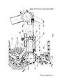
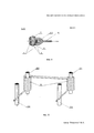
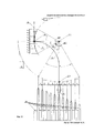
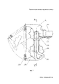
Предлагаемое изобретение иллюстрируется чертежами. На фиг. 1 показан задний переключатель передач велосипеда - вид спереди; на фиг. 2 показан задний переключатель передач велосипеда - разрез по А-А; на фиг. 3 показан задний переключатель передач велосипеда - разрез по В-В; на фиг. 4 показана поворотная втулка с приводным тросом, установленная на выступе внутреннего рычага шарнирного параллелограмма - разрез по С-С; на фиг. 5 показано крепление возвратной пружины кручения - вид спереди; на фиг. 6 схематично показаны повороты рычагов шарнирного параллелограмма и переносы направляющего ролика относительно ведомых шестеренок кассеты заднего колеса велосипеда; на фиг. 7 показано крепление пружины растяжение к корпусу переключателя и к поворотной пластине - вид спереди; на фиг. 8 показано крепление направляющего и натяжного роликов, поворотной и ограничительной пластин на корпусе переключателя - разрез по N-N.The invention is illustrated by drawings. In FIG. 1 shows a bicycle rear gear shifter, front view; in FIG. 2 shows a bicycle rear gear selector — section along AA; in FIG. 3 shows a bicycle rear gear selector - a section along BB; in FIG. 4 shows a rotary sleeve with a drive cable mounted on the protrusion of the internal lever of the articulated parallelogram - section along CC; in FIG. 5 shows the fastening of the return torsion spring - front view; in FIG. 6 schematically shows the rotation of the levers of the articulated parallelogram and the transfers of the guide roller relative to the driven gears of the cassette of the rear wheel of the bicycle; in FIG. 7 shows the attachment of a tension spring to the switch housing and to the rotary plate — front view; in FIG. Figure 8 shows the fastening of the guide and tension rollers, the rotary and restrictive plates on the switch housing - section along N-N.
Задний переключатель передач велосипеда состроит из кронштейна 1 с установленными на нем через оси 2.1 и 2.2 внутренним 3 и внешним 4 рычагами шарнирного параллелограмма с поворотной втулкой 5, в которой установлен приводной трос 6 с ограничительной бобышкой 6.1, и закрепленной запорным шплинтом 7 с разрезной пластиной 8. Свободные края внутреннего 3 и внешнего 4 рычагов шарнирного параллелограмма крепятся через оси 2.3 и 2.4 к корпусу переключателя 9. На оси 2.1. и 2.3 установлена возвратная пружина кручения 10. Для ограничения поворота внутреннего 3 и внешнего 4 рычагов шарнирного параллелограмма предусмотрены ограничительные винты 11 и 12, установленные в кронштейне 1. В корпус переключателя 9 установлена несущая втулка 13 с направляющим роликом 14 через подшипники 15.1 и 15.2. и распорную шайбу 16. В несущую втулку 13 установлена предварительно закрученная и напряженная пружина кручения 17 и закреплена в ней стяжным винтом 18, закрученным по резьбе в поворотную пластину 19 на которой установлен натяжной ролик 20 и ограничительная пластина 21 со стопорным винтом 22. Приводная цепь 23 размещена между натяжным роликом 20 и направляющим роликом 14, и установлена на одной из ведомых шестеренок кассеты 24 заднего колеса велосипеда, закрепленного в задней вилке рамы велосипеда 25 стяжной осью 26. Кронштейн 1 установлен на нижнем правом пере задней вилки рамы велосипеда 25.1 и закреплен стяжным болтом 27. Регулировка натяжения приводного троса 6 производится регулировочным вином 28, установленным по резьбе на выступе 29 кареточного узла рамы велосипеда 25.2. Регулировочный винт 28 имеет сквозное отверстие, через которое проходит приводной трос 6, и цилиндрическую выточку, в которую установлен направляющий боуден 30. Кроме того, натяжение приводной цепи 23 может производится пружиной растяжения 31, установленной на выступах корпуса переключателя 9 и поворотной пластины 19, а скрепление пластин 19 и 21 между собой производится стягивающим винтом 32.The rear gear selector of the bicycle will be constructed from the
Переключатель передач работает следующим образом. При натяжении приводного троса 6 и уменьшении его длины между упором направляющего боудена 30 и поворотной втулкой 5 на величину ![]()
![]()
![]()
![]()
Claims (15)
Priority Applications (1)
| Application Number | Priority Date | Filing Date | Title |
|---|---|---|---|
| RU2017115619A RU2656001C1 (en) | 2017-05-03 | 2017-05-03 | Rear bicycle gear selector |
Applications Claiming Priority (1)
| Application Number | Priority Date | Filing Date | Title |
|---|---|---|---|
| RU2017115619A RU2656001C1 (en) | 2017-05-03 | 2017-05-03 | Rear bicycle gear selector |
Publications (1)
| Publication Number | Publication Date |
|---|---|
| RU2656001C1 true RU2656001C1 (en) | 2018-05-30 |
Family
ID=62560168
Family Applications (1)
| Application Number | Title | Priority Date | Filing Date |
|---|---|---|---|
| RU2017115619A RU2656001C1 (en) | 2017-05-03 | 2017-05-03 | Rear bicycle gear selector |
Country Status (1)
| Country | Link |
|---|---|
| RU (1) | RU2656001C1 (en) |
Citations (4)
| Publication number | Priority date | Publication date | Assignee | Title |
|---|---|---|---|---|
| FR1030589A (en) * | 1950-07-19 | 1953-06-15 | Volmarsteiner Metallwaren Ind | Gear shifting bicycles |
| US4051738A (en) * | 1976-07-06 | 1977-10-04 | Beatrice Foods Co. | Single point resilient and adjustable mount for derailler |
| US6350212B1 (en) * | 1999-04-13 | 2002-02-26 | Campagnolo Srl | Rear derailleur of a bicycle |
| RU2237591C2 (en) * | 1997-04-29 | 2004-10-10 | Шимано Инк. | Bicycle change-speed control mechanism |
-
2017
- 2017-05-03 RU RU2017115619A patent/RU2656001C1/en active
Patent Citations (4)
| Publication number | Priority date | Publication date | Assignee | Title |
|---|---|---|---|---|
| FR1030589A (en) * | 1950-07-19 | 1953-06-15 | Volmarsteiner Metallwaren Ind | Gear shifting bicycles |
| US4051738A (en) * | 1976-07-06 | 1977-10-04 | Beatrice Foods Co. | Single point resilient and adjustable mount for derailler |
| RU2237591C2 (en) * | 1997-04-29 | 2004-10-10 | Шимано Инк. | Bicycle change-speed control mechanism |
| US6350212B1 (en) * | 1999-04-13 | 2002-02-26 | Campagnolo Srl | Rear derailleur of a bicycle |
Similar Documents
| Publication | Publication Date | Title |
|---|---|---|
| US10065705B2 (en) | Bicycle derailleur | |
| TWI585001B (en) | Bicycle transmission | |
| US10604212B2 (en) | Bicycle rear derailleur with a motion resisting structure | |
| CN109110041B (en) | Damper for bicycle component | |
| CN108995759B (en) | Bicycle rear derailleur and damper device for a bicycle rear derailleur | |
| US9573653B2 (en) | Motor driven derailleur for a bicycle gearshift | |
| US7963870B2 (en) | Bicycle rear derailleur | |
| US7396304B2 (en) | Bicycle rear derailleur | |
| TWI388465B (en) | Bicycle derailleur | |
| US20070191159A1 (en) | Bicycle derailleur | |
| EP3436333B1 (en) | Rear derailleur for a bicycle | |
| US9248885B2 (en) | Derailleur | |
| US20100113200A1 (en) | Bicycle chain tensioner | |
| US9156524B2 (en) | Derailleur | |
| US9623932B2 (en) | Bicycle derailleur | |
| WO2018171522A1 (en) | Rear derailleur having additional rotation resistance function and resistance applying method | |
| US20130079184A1 (en) | Bicycle rear derailleur | |
| US20080229863A1 (en) | Reach Adjust for a Handlebar-Mounted Lever Assembly | |
| US7674198B2 (en) | Bicycle rear derailleur | |
| DE102013104370B4 (en) | Bicycle power unit and electrically assisted bicycle | |
| US20060194660A1 (en) | Bicycle derailleur with a motion limiting structure | |
| US12589830B2 (en) | Bicycle gear shifting system | |
| US20140357436A1 (en) | Bicycle chain tensioner | |
| US20140216198A1 (en) | Cable adjusting unit | |
| RU2656001C1 (en) | Rear bicycle gear selector |