RU2522215C1 - Vibrating-rolling walker - Google Patents
Vibrating-rolling walker Download PDFInfo
- Publication number
- RU2522215C1 RU2522215C1 RU2012154528/11A RU2012154528A RU2522215C1 RU 2522215 C1 RU2522215 C1 RU 2522215C1 RU 2012154528/11 A RU2012154528/11 A RU 2012154528/11A RU 2012154528 A RU2012154528 A RU 2012154528A RU 2522215 C1 RU2522215 C1 RU 2522215C1
- Authority
- RU
- Russia
- Prior art keywords
- rim
- drive shaft
- wheel
- gear
- pipe
- Prior art date
Links
- 238000005096 rolling process Methods 0.000 title claims description 9
- 230000009977 dual effect Effects 0.000 claims abstract description 4
- 230000008878 coupling Effects 0.000 abstract 1
- 238000010168 coupling process Methods 0.000 abstract 1
- 238000005859 coupling reaction Methods 0.000 abstract 1
- 230000000694 effects Effects 0.000 abstract 1
- 239000000126 substance Substances 0.000 abstract 1
- DOSMHBDKKKMIEF-UHFFFAOYSA-N 2-[3-(diethylamino)-6-diethylazaniumylidenexanthen-9-yl]-5-[3-[3-[4-(1-methylindol-3-yl)-2,5-dioxopyrrol-3-yl]indol-1-yl]propylsulfamoyl]benzenesulfonate Chemical compound C1=CC(=[N+](CC)CC)C=C2OC3=CC(N(CC)CC)=CC=C3C(C=3C(=CC(=CC=3)S(=O)(=O)NCCCN3C4=CC=CC=C4C(C=4C(NC(=O)C=4C=4C5=CC=CC=C5N(C)C=4)=O)=C3)S([O-])(=O)=O)=C21 DOSMHBDKKKMIEF-UHFFFAOYSA-N 0.000 description 9
- 238000006073 displacement reaction Methods 0.000 description 3
- 239000010426 asphalt Substances 0.000 description 2
- 238000005265 energy consumption Methods 0.000 description 2
- 230000000903 blocking effect Effects 0.000 description 1
- 230000003993 interaction Effects 0.000 description 1
- 230000035939 shock Effects 0.000 description 1
Images


Landscapes
- Transmission Devices (AREA)
- Braking Arrangements (AREA)
Abstract
Description
Изобретение относится к транспортной технике, в частности к вездеходам на многофункциональных энергоэффективных движителях повышенной проходимости.The invention relates to transport equipment, in particular to all-terrain vehicles on multifunctional energy-efficient off-road engines.
Известен шаговый движитель [1], состоящий из двух полукатков, установленных на противоположных концах поворотного полого водила с возможностью свободного осевого поворота.Known stepper mover [1], consisting of two half-rollers mounted on opposite ends of a rotary hollow carrier with the possibility of free axial rotation.
Недостатками данного движителя являются низкая скорость и высокие энергозатраты при движении по поверхности с твердым покрытием, например асфальтобетонным.The disadvantages of this mover are low speed and high energy consumption when moving on a surface with a hard surface, such as asphalt.
Известен колесный движитель [2], обод и шина которого разделены на секции, одним концом шарнирно связанные с диском ступицы, а вторым концом соединенные с механизмом отклонения с возможностью отклонения всех секций одновременно на выбранный угол.Known wheel mover [2], the rim and tire of which are divided into sections, one end pivotally connected to the hub disk, and the other end connected to the deflection mechanism with the possibility of deviation of all sections simultaneously to the selected angle.
Недостатками данного движителя является сложность конструкции, пониженная надежность и проходимость по пересеченной местности.The disadvantages of this mover is the complexity of the design, reduced reliability and cross-country ability.
Наиболее близким по технической сущности к заявляемому изобретению относится движитель [3], состоящий из двух колес одинакового диаметра, соединенных коленвалом. Между колесами на полуосях расположены лопатки, на нижних кромках которых могут быть установлены лопасти.The closest in technical essence to the claimed invention relates to a mover [3], consisting of two wheels of the same diameter connected by a crankshaft. Blades are located between the wheels on the semiaxes, on the lower edges of which blades can be installed.
Недостатком данного движителя являются повышенные энергозатраты, пониженная геометрическая проходимость на пересеченной местности и малая скорость движения по поверхности с твердым покрытием, например асфальтобетонным, вследствие выступающих за колеса частей движителя.The disadvantage of this mover is increased energy consumption, reduced geometric cross-country ability on rough terrain and low speed on the surface with a hard surface, such as asphalt, due to the protruding parts of the mover beyond the wheels.
Техническая задача - повышение проходимости по поверхностям с различной несущей способностью и пересеченной местности, повышение надежности, скорости и энергоэффективности до уровня стандартных пневмоколесных при движении по твердому покрытию.The technical task is to increase cross-country ability on surfaces with different bearing capacity and rough terrain, increase reliability, speed and energy efficiency to the level of standard pneumatic wheels when driving on hard surfaces.
Техническая задача достигается тем, что на приводной вал движителя установлена муфта синхронизации и внутренний обод, с внешней стороны которого соосно с приводным валом смонтирована труба с внутренней резьбой и гайкой совместно со шлицевой трубкой, установленной на шлицах приводного вала, на шлицевой трубке соосно с ней смонтированы тормозной диск, а также зубчатое колесо и ползун, охватывающий параллельные направляющие внешнего обода, с возможностью свободного вращения относительно шлицевой трубки. А на внешнем ободе двухскатного колеса установлены две параллельные рейки зацепления с зубчатым колесом, одна из которых неподвижна, вторая подвижна относительно зацепления с зубчатым колесом, а также тормозная колодка подвижной рейки. Также на внешней стороне внутреннего обода и внутренней стороне внешнего обода двухскатного колеса на максимальном радиусе обода расположены цилиндрические выступы, для которых расстояния между соседними выступами равны диаметру одного выступа, а торцы цилиндрических выступов выполнены конусообразными.The technical problem is achieved by the fact that a synchronization clutch and an inner rim are installed on the drive shaft of the mover, on the outside of which a pipe with an internal thread and a nut is mounted coaxially with the splined tube installed on the splines of the drive shaft, mounted on the splined tube coaxially with it a brake disk, as well as a gear and a slider, covering the parallel guides of the outer rim, with the possibility of free rotation relative to the spline tube. And on the outer rim of the gable wheel there are two parallel gear racks with a gear wheel, one of which is stationary, the second is movable relative to gearing with a gear wheel, and also a brake shoe of a movable rack. Also on the outer side of the inner rim and the inner side of the outer rim of the gable wheel at the maximum radius of the rim are cylindrical protrusions, for which the distances between adjacent protrusions are equal to the diameter of one protrusion, and the ends of the cylindrical protrusions are made conical.
Таким образом, можно предположить, что заявленный многофункциональный движитель повышенной проходимости соответствует критерию “новизна”.Thus, it can be assumed that the claimed multifunctional cross-country propulsion system meets the criterion of “novelty”.
Сравнение заявляемого решения не только с прототипом, но и с другими техническими решениями в данной области движителей высокой проходимости позволяет сделать вывод об отсутствии признаков, сходных с существенными отличительными признаками в заявляемом многофункциональном движителе высокой проходимости, поэтому заявляемое техническое решение соответствует критерию “изобретательский уровень”.Comparison of the claimed solution not only with the prototype, but also with other technical solutions in this area of high-traffic propulsion devices allows us to conclude that there are no signs similar to the essential distinguishing features of the claimed multi-functional high-traffic propulsion, therefore, the claimed technical solution meets the criterion of “inventive step”.
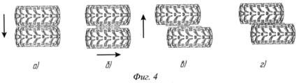
Изобретение поясняется чертежами. На фиг.1 движитель представлен в разрезе; на фиг.2 - разрез внутренней части движителя по Б-Б на фиг.1; на фиг.3. - вид части движителя сбоку по А на фиг.1; на фиг.4. - последовательность этапов смены режимов работы движителя; на фиг.5. - принцип движения с поднятием корпуса.The invention is illustrated by drawings. In Fig.1, the mover is presented in section; figure 2 is a section of the inner part of the mover along BB in figure 1; figure 3. - side view of the mover on the side of A in figure 1; figure 4. - the sequence of stages of changing the operating modes of the propulsion device; figure 5. - The principle of movement with the raising of the body.
Шаговиброкат (см. фиг.1) содержит внутренний обод 1 двухскатного колеса с возможностью свободного вращения на приводном валу 2, на котором установлена муфта синхронизации 3. С внешней стороны внутреннего обода 1 двухскатного колеса соосно с приводным валом 2 закреплена труба 4 с внутренней резьбой и гайкой 5, зафиксированной на шлицевой трубке 6, установленной на шлицах 7 приводного вала 2 с возможностью продольного перемещения вдоль своей оси. На шлицевой трубке 6 установлены жестко тормозной диск 8 и зубчатое колесо 9 с возможностью свободного вращения. На шлицевой трубке 6 также установлен с возможностью свободного вращения ползун 10, который охватывает параллельные направляющие 11 внешнего обода 12 двухскатного колеса. На внешнем ободе двухскатного колеса 12 установлены в зацеплении с зубчатым колесом 9 неподвижная зубчатая рейка 13 и подвижная зубчатая рейка 14 с возможностью продольного смещения по касательной к зубчатому колесу 9. На внешнем ободе двухскатного колеса 12 смонтирована тормозная колодка 15. По внешней стороне внутреннего обода 1 и внутренней стороне внешнего обода 12 двухскатного колеса на максимальном радиусе обода расположены цилиндрические выступы 16 и 17, для которых расстояния между соседними выступами равны диаметру одного выступа. Тормозное устройство 18 рабочей тормозной системы транспортного средства смонтировано с внутренней стороны внутреннего обода 1 двухскатного колеса.A step-rolling machine (see Fig. 1) contains an inner rim 1 of a gable wheel with the possibility of free rotation on a drive shaft 2, on which a synchronization clutch 3 is installed. On the outside of the inner rim 1 of a gable wheel, a
Устройство работает следующим образом в режимах качения, шагания и виброкачения.The device operates as follows in the modes of rolling, walking and vibration.
При работе в режиме качения (фиг.1, фиг.4а) внутренний обод 1 и внешний обод 12 двухскатного колеса расположены соосно, гайка 5 полностью ввинчена в трубу 4 с внутренней резьбой, а муфта синхронизации 3 включена и передает крутящий момент от приводного вала 2 на внутренний обод 1 двухскатного колеса. При этом цилиндрические выступы 16 и 17 входят в зацепление друг с другом, передавая крутящий момент с внутреннего обода 1 на внешний обод 12 двухскатного колеса, и движитель работает как обычное двухскатное колесо.When operating in the rolling mode (Fig. 1, Fig. 4a), the inner rim 1 and the
Смена режима движения движителя происходит следующим образом (фиг.1, фиг.2, фиг.4б, фиг.4в, фиг.4г). Муфта синхронизации 3 отключается от внутреннего обода 1 двухскатного колеса, а тормозное устройство 18 рабочей тормозной системы транспортного средства включается, препятствуя вращению внутреннего 1 и внешнего обода 12 двухскатного колеса. При передаче крутящего момента вращением приводного вала 2 гайка 5, будучи жестко зафиксированной на шлицевой трубке 6, вращается относительно трубы 4 с внутренней резьбой. Происходит выкручивание гайки 5 из трубы 4 с внутренней резьбой и перемещение шлицевой трубка 6 совместно с гайкой 5 вдоль шлицев 7 приводного вала 2 с одновременным перемещением скатов двухскатного колеса в осевом направлении друг от друга (фиг.4б). Когда величина этого перемещения достигает значения, при котором цилиндрические выступы 16 и 17 выходят из зацепления друг с другом, включается вращающийся вместе с шлицевой трубкой 6 тормозной диск 8, приводя во вращение зубчатое колесо 9. Одновременно с включением тормозного диска 8 отключается тормозная колодка 15, освобождая подвижную рейку 14 и давая возможность зубчатому колесу 9 переместиться по неподвижной зубчатой рейке 13. При этом внешний обод 12 двухскатного колеса сдвигается по радиусу относительно ползуна 10 вдоль направляющих 11 (фиг.4в). По достижении требуемой величины смещения скатов двухскатного колеса вновь включается тормозная колодка 15, блокируя внешний обод 12 двухскатного колеса от дальнейшего смещения, тормозной диск 8 отключается и производится смена направления вращения приводного вала 2 на противоположное. При этом гайка 5 завинчивается в трубу 4 с внутренней резьбой, перемещая шлицевую трубку 6 в обратном направлении. Происходит осевое перемещение внешнего обода 12 двухскатного колеса по направлению к внутреннему ободу 1 двухскатного колеса. При этом цилиндрические выступы 16 и 17 полностью входят в зацепление друг с другом и фиксируют положение сдвинутых по радиусу относительно друг друга внутреннего и внешнего ободьев двухскатного колеса. Последующее выключение тормозного устройства 18 рабочей тормозной системы и включение муфты синхронизации 3 обеспечивает функционирование движителя в режиме виброкачения или шагания с поднятием корпуса транспортного средства (фиг.5).The change of motion mode of the propulsion device is as follows (Fig. 1, Fig. 2, Fig. 4b, Fig. 4c, Fig. 4d). The synchronization clutch 3 is disconnected from the inner rim 1 of the gable wheel, and the brake device 18 of the working brake system of the vehicle is turned on, preventing the rotation of the inner 1 and
Режим шагания, с поднятием корпуса транспортного средства, реализуется приводными валами (полуосями) мостов транспортного средства, при смещенных по радиусу скатов двухскатного колеса друг относительно друга на расстояние до половины диаметра обода колеса и невысокой угловой скорости вращения приводного вала.The walking mode, with the raising of the vehicle body, is realized by the drive shafts (half shafts) of the vehicle bridges, when the slopes of the gable wheel are shifted along the radius of the slope relative to each other by a distance of half the diameter of the wheel rim and the low angular speed of rotation of the drive shaft.
При минимальном смещении по радиусу скатов двухскатного колеса друг относительно друга и высокой угловой скорости вращения приводного вала реализуется режим виброкачения.With a minimum shift along the radius of the slopes of the gable wheel relative to each other and a high angular velocity of rotation of the drive shaft, the vibration mode is implemented.
Повышение проходимости движителя достигается за счет его переключения в специальный режим движения повышенной проходимости - режим шагания с поднятием корпуса транспортного средства или виброкачения. В первом случае достигается динамическое увеличение клиренса и углов продольной проходимости, обеспечивающих перешагивание препятствий и движение по пересеченной местности. При этом также меняется сам характер взаимодействия движителя с опорной поверхностью благодаря тому, что помимо накатывания имеет место наступание. Во втором случае смещенное колесо работает как грунтозацеп, а также создает дополнительное динамическое усилие за счет вибродинамических ударов, повышающее коэффициент сцепления движителя с опорной поверхностью. Повышение энергоэффективности и скорости движителя достигается путем выбора оптимального режима работы в зависимости от типа опорной поверхности - режим качения при движении на твердых поверхностях и режим шагания с поднятием корпуса машины или виброкачения при препятствиях и движении по пересеченной местности или поверхностях со слабой несущей способностью.Enhanced patency of the mover is achieved by switching it to a special mode of movement of increased terrain - walking mode with the raising of the vehicle body or vibration. In the first case, a dynamic increase in clearance and angles of longitudinal patency is achieved, providing overstepping of obstacles and movement over rough terrain. At the same time, the very nature of the interaction of the mover with the supporting surface changes due to the fact that in addition to rolling, an offensive takes place. In the second case, the displaced wheel works as a lug, and also creates additional dynamic force due to vibrodynamic shocks, which increases the coefficient of adhesion of the mover to the supporting surface. Improving energy efficiency and propulsion speed is achieved by choosing the optimal operating mode depending on the type of supporting surface - the rolling mode when moving on hard surfaces and the walking mode with lifting the machine body or vibration when obstacles and movement over rough terrain or surfaces with weak bearing capacity.
Повышение надежности обеспечивается применением апробированных стандартных двухскатных колес и ступиц с пневматическими шинами.Improving reliability is ensured by the use of proven standard dual wheels and hubs with pneumatic tires.
Источники информацииInformation sources
1. Патент РФ №2365519, МПК B62D 57/00.1. RF patent No. 2365519, IPC B62D 57/00.
2. Патент РФ №2280562, МПК В60В 19/00, В60К 17/14.2. RF patent No. 2280562, IPC BVV 19/00, BKK 17/14.
3. Патент РФ №2293040, МПК В63Н 1/04.3. RF patent No. 2293040, IPC V63H 1/04.
Claims (3)
Priority Applications (1)
| Application Number | Priority Date | Filing Date | Title |
|---|---|---|---|
| RU2012154528/11A RU2522215C1 (en) | 2012-12-14 | 2012-12-14 | Vibrating-rolling walker |
Applications Claiming Priority (1)
| Application Number | Priority Date | Filing Date | Title |
|---|---|---|---|
| RU2012154528/11A RU2522215C1 (en) | 2012-12-14 | 2012-12-14 | Vibrating-rolling walker |
Publications (2)
| Publication Number | Publication Date |
|---|---|
| RU2012154528A RU2012154528A (en) | 2014-06-20 |
| RU2522215C1 true RU2522215C1 (en) | 2014-07-10 |
Family
ID=51213777
Family Applications (1)
| Application Number | Title | Priority Date | Filing Date |
|---|---|---|---|
| RU2012154528/11A RU2522215C1 (en) | 2012-12-14 | 2012-12-14 | Vibrating-rolling walker |
Country Status (1)
| Country | Link |
|---|---|
| RU (1) | RU2522215C1 (en) |
Citations (5)
| Publication number | Priority date | Publication date | Assignee | Title |
|---|---|---|---|---|
| JP2005212657A (en) * | 2004-01-30 | 2005-08-11 | Ntn Corp | Motorized wheel driving device |
| RU2266842C1 (en) * | 2004-06-29 | 2005-12-27 | Сагаков Станислав Святославович | Vehicle wheeled-walking propulsion unit |
| RU2280562C2 (en) * | 2004-10-13 | 2006-07-27 | Геральд Иванович Денисенко | Wheeled propulsion unit |
| RU2293040C1 (en) * | 2005-09-09 | 2007-02-10 | Станислав Святославович Сагаков | Wheeled and bladed propulsor |
| RU2365519C1 (en) * | 2007-11-30 | 2009-08-27 | Государственное образовательное учреждение высшего профессионального образования Московский государственный технический университет "МАМИ" | Vehicle step propulsor |
-
2012
- 2012-12-14 RU RU2012154528/11A patent/RU2522215C1/en not_active IP Right Cessation
Patent Citations (5)
| Publication number | Priority date | Publication date | Assignee | Title |
|---|---|---|---|---|
| JP2005212657A (en) * | 2004-01-30 | 2005-08-11 | Ntn Corp | Motorized wheel driving device |
| RU2266842C1 (en) * | 2004-06-29 | 2005-12-27 | Сагаков Станислав Святославович | Vehicle wheeled-walking propulsion unit |
| RU2280562C2 (en) * | 2004-10-13 | 2006-07-27 | Геральд Иванович Денисенко | Wheeled propulsion unit |
| RU2293040C1 (en) * | 2005-09-09 | 2007-02-10 | Станислав Святославович Сагаков | Wheeled and bladed propulsor |
| RU2365519C1 (en) * | 2007-11-30 | 2009-08-27 | Государственное образовательное учреждение высшего профессионального образования Московский государственный технический университет "МАМИ" | Vehicle step propulsor |
Also Published As
| Publication number | Publication date |
|---|---|
| RU2012154528A (en) | 2014-06-20 |
Similar Documents
| Publication | Publication Date | Title |
|---|---|---|
| CN207889812U (en) | The novel steering wheel driving device of double-wheel differential type driving | |
| US5884526A (en) | Actuator for transfer case | |
| KR102422868B1 (en) | Drive configuration | |
| JP6267708B2 (en) | Rocking differential with preload spring combination for contact maintenance | |
| US11091022B2 (en) | Centreless wheel with drive | |
| EP1929180B1 (en) | Pulley assembly for a continuously variable transmission | |
| KR101351073B1 (en) | Variable radius pulley and continuously variable transmission | |
| CN101323252B (en) | Cone-disk clutch cam self-adapting automatic transmission hub | |
| RU2522215C1 (en) | Vibrating-rolling walker | |
| US5782328A (en) | Transfer case with selectively grounded member | |
| CN105711336A (en) | Electric car rear axle with infinitely variable-speed wheels and width adjusting function | |
| US4509388A (en) | Differential gear | |
| KR101273485B1 (en) | Variable radius pulley and continuously variable transmission | |
| US4343205A (en) | Differential | |
| CN109367322A (en) | Robotically-driven chassis | |
| CN116080304B (en) | Deformable tire, control method and vehicle | |
| US9062750B2 (en) | Differential gears with a mechanism for controlling differential motion | |
| RU2279987C1 (en) | Vehicle wheel drive | |
| US2967580A (en) | Composite wheel | |
| CN111853201B (en) | An overrunning differential | |
| CN109334444A (en) | Heavy-duty car wheel side drive mechanism | |
| JPS58136563A (en) | Three-wheeled vehicle for wasteland driving | |
| CN201554783U (en) | Semi- joining sleeve of infinitely variable transmission | |
| CN102767609A (en) | Continuously variable transmission driver disk | |
| CN102826159A (en) | Energy-saving assist driving wheel of stepless speed change motorcycle |
Legal Events
| Date | Code | Title | Description |
|---|---|---|---|
| MM4A | The patent is invalid due to non-payment of fees |
Effective date: 20141215 |