RU2307254C1 - Nozzle box assembly for high-temperature cylinder of steam turbine - Google Patents
Nozzle box assembly for high-temperature cylinder of steam turbine Download PDFInfo
- Publication number
- RU2307254C1 RU2307254C1 RU2006105676/06A RU2006105676A RU2307254C1 RU 2307254 C1 RU2307254 C1 RU 2307254C1 RU 2006105676/06 A RU2006105676/06 A RU 2006105676/06A RU 2006105676 A RU2006105676 A RU 2006105676A RU 2307254 C1 RU2307254 C1 RU 2307254C1
- Authority
- RU
- Russia
- Prior art keywords
- section
- box assembly
- steam
- nozzle box
- steam turbine
- Prior art date
Links
- 230000007704 transition Effects 0.000 claims description 6
- 238000010438 heat treatment Methods 0.000 abstract description 4
- 238000004519 manufacturing process Methods 0.000 abstract description 4
- 239000002184 metal Substances 0.000 abstract description 3
- 230000001052 transient effect Effects 0.000 abstract 2
- 230000000694 effects Effects 0.000 abstract 1
- 239000000126 substance Substances 0.000 abstract 1
- 238000005266 casting Methods 0.000 description 3
Images

Landscapes
- Turbine Rotor Nozzle Sealing (AREA)
Abstract
Description
Изобретение относится к области энергетики, к турбиностроению.The invention relates to the field of energy, to turbine engineering.
Известны сопловые коробки для высокотемпературного цилиндра паровой турбины, литые, с вертикальным подводом пара (Трухний А.Д. Стационарные паровые турбины. - М.: Энергоатомиздат. 1990. С.265).Known nozzle boxes for a high-temperature cylinder of a steam turbine, cast, with vertical steam supply (Trukhny AD Stationary steam turbines. - M .: Energoatomizdat. 1990. P.265).
Недостатком известных сопловых коробок является то, что при таком подводе происходит неравномерное заполнение паром сопел.A disadvantage of the known nozzle boxes is that with such a supply, the nozzles are not uniformly filled with steam.
Известны сопловые коробки для высокотемпературного цилиндра паровой турбины, выполненные при помощи литья (Трухний А.Д., Ломакин Б.В. Теплофикационные паровые турбины и турбоустановки. - М.: Издательство МЭИ, 2002. С.265. Рис.9.5).Known nozzle boxes for the high temperature cylinder of a steam turbine made by casting (Truhniy A.D., Lomakin B.V. Heating steam turbines and turbines. - M.: MEI Publishing House, 2002. P.265. Fig. 9.5).
Это известное устройство является наиболее близким устройством аналогичного назначения к предлагаемому по совокупности признаков и принято за прототип.This known device is the closest device of a similar purpose to the proposed combination of features and is taken as a prototype.
Недостатком устройства, принятого за прототип, а также причиной, препятствующей достижению предлагаемого технического результата при использовании известного устройства по прототипу, является то, что не представляется возможным выполнение сравнительно тонких литых стенок, что приводит к увеличению металлоемкости, а необходимость изготовления моделей для отливки удорожает изготовление устройства.The disadvantage of the device adopted for the prototype, as well as the reason that impedes the achievement of the proposed technical result when using the known device of the prototype, is that it is not possible to perform relatively thin cast walls, which leads to an increase in metal consumption, and the need to manufacture models for casting makes manufacturing more expensive devices.
Проведенный заявителем анализ уровня техники, включающий поиск по патентным и научно-техническим источникам информации, а также выявление источников, содержащих сведения об аналогах заявленного изобретения, позволили установить, что заявитель не обнаружил технического решения, характеризующегося признаками, тождественными или эквивалентными предлагаемым.The analysis of the prior art by the applicant, including a search by patent and scientific and technical sources of information, as well as identification of sources containing information about analogues of the claimed invention, allowed to establish that the applicant did not find a technical solution characterized by signs identical or equivalent to those proposed.
Определение из перечня выявленных аналогов прототипа, как наиболее близкого технического решения по совокупности признаков, позволило выявить в заявленном устройстве совокупность существенных отличительных признаков по отношению к усматриваемому заявителем техническому результату, изложенную в нижеприведенной формуле изобретения.The definition from the list of identified analogues of the prototype, as the closest technical solution for the totality of features, allowed to identify in the claimed device a combination of significant distinctive features in relation to the applicant's perceived technical result, set forth in the following claims.
Заявляемое техническое решение позволяет обеспечить минимальную трудоемкость и металлоемкость изготовления, а также из-за более тонких стенок сварной конструкции до минимума сократить время прогрева сопловой коробки и, соответственно, время пуска паровой высокотемпературной турбины, что приводит к повышению ее надежности и маневренности.The claimed technical solution allows to ensure minimal labor and metal production, and also due to the thinner walls of the welded structure to minimize the heating time of the nozzle box and, accordingly, the start-up time of the steam high-temperature turbine, which increases its reliability and maneuverability.
Предложена сопловая коробка высокотемпературного цилиндра паровой турбины, включающая участки - подводящий, переходной и участок, раздающий пар на сегменты сопел, при этом коробка выполнена из сваренных между собой участков, подводящий участок выполнен из трубы, переходной участок выполнен в виде конуса, переходящего с трубы на овал, а участок, раздающий пар на сегменты сопел, выполнен из двух колец - наружного и внутреннего с заглушками на торцах.A nozzle box of a high-temperature cylinder of a steam turbine is proposed, including sections — supply, transition, and section distributing steam to nozzle segments, while the box is made of sections welded to each other, the supply section is made of pipe, the transition section is made in the form of a cone passing from pipe to the oval, and the section dispensing steam to the nozzle segments is made of two rings - the outer and the inner with plugs at the ends.
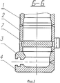
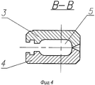
Изобретение иллюстрируется чертежами, где на фиг.1 показан продольный разрез сопловой коробки, на фиг.2 - вид А по фиг.1, на фиг.3 - разрез Б-Б по фиг.1, на фиг.4 - разрез В-В по фиг.1.The invention is illustrated by drawings, where Fig. 1 shows a longitudinal section of a nozzle box, Fig. 2 is a view A from Fig. 1, Fig. 3 is a section B-B in Fig. 1, Fig. 4 is a section BB in figure 1.
Сопловая коробка включает подводящий участок, выполненный в виде трубы 1, переходной участок 2, выполненный в виде конуса, переходящего с трубы на овал, и участок, раздающий пар на сегменты сопел, выполненный из двух колец - наружного 3 и внутреннего 4 с заглушками 5 на торцах. Плоские участки 6 переходного участка 2 подкреплены стержнем 7. Участки сопловой коробки сварены между собой.The nozzle box includes an inlet section made in the form of a
При пуске паровой турбины в сопловую коробку поступает пар. Благодаря тонким стенкам сварной конструкции она достаточно быстро прогревается. Толщина стенок в сварной конструкции определяется по допускаемым напряжениям, в литой конструкции - возможностями литья. Быстрая прогреваемость сопловых коробок сокращает время пуска высокотемпературной паровой турбины, что повышает ее маневренность.When starting a steam turbine, steam enters the nozzle box. Thanks to the thin walls of the welded structure, it quickly warms up. The wall thickness in a welded structure is determined by the permissible stresses, in a cast structure - by casting capabilities. The quick heating of the nozzle boxes reduces the start-up time of a high-temperature steam turbine, which increases its maneuverability.
Claims (1)
Priority Applications (1)
| Application Number | Priority Date | Filing Date | Title |
|---|---|---|---|
| RU2006105676/06A RU2307254C1 (en) | 2006-02-20 | 2006-02-20 | Nozzle box assembly for high-temperature cylinder of steam turbine |
Applications Claiming Priority (1)
| Application Number | Priority Date | Filing Date | Title |
|---|---|---|---|
| RU2006105676/06A RU2307254C1 (en) | 2006-02-20 | 2006-02-20 | Nozzle box assembly for high-temperature cylinder of steam turbine |
Publications (1)
| Publication Number | Publication Date |
|---|---|
| RU2307254C1 true RU2307254C1 (en) | 2007-09-27 |
Family
ID=38954229
Family Applications (1)
| Application Number | Title | Priority Date | Filing Date |
|---|---|---|---|
| RU2006105676/06A RU2307254C1 (en) | 2006-02-20 | 2006-02-20 | Nozzle box assembly for high-temperature cylinder of steam turbine |
Country Status (1)
| Country | Link |
|---|---|
| RU (1) | RU2307254C1 (en) |
Citations (5)
| Publication number | Priority date | Publication date | Assignee | Title |
|---|---|---|---|---|
| GB1109457A (en) * | 1964-11-17 | 1968-04-10 | Worthington Corp | Segmented diaphragm assembly for turbines |
| US4616975A (en) * | 1984-07-30 | 1986-10-14 | General Electric Company | Diaphragm for a steam turbine |
| SU1749493A1 (en) * | 1990-11-05 | 1992-07-23 | Производственное Объединение Атомного Турбостроения "Харьковский Турбинный Завод" Им.С.М.Кирова | Steam turbine nozzle box |
| RU2211338C2 (en) * | 2001-11-12 | 2003-08-27 | Открытое акционерное общество "Ленинградский Металлический завод" | Device for nozzle steam distribution in high-pressure cylinder of steam turbine |
| RU2003114529A (en) * | 2002-05-17 | 2004-11-10 | Дженерал Электрик Компани | NOZZLE BOX OF STEAM TURBINE WITH LOCATION OF EXHAUST NOZZLES IN A 360 ° CIRCLE |
Family Cites Families (1)
| Publication number | Priority date | Publication date | Assignee | Title |
|---|---|---|---|---|
| US6631858B1 (en) * | 2002-05-17 | 2003-10-14 | General Electric Company | Two-piece steam turbine nozzle box featuring a 360-degree discharge nozzle |
-
2006
- 2006-02-20 RU RU2006105676/06A patent/RU2307254C1/en active
Patent Citations (5)
| Publication number | Priority date | Publication date | Assignee | Title |
|---|---|---|---|---|
| GB1109457A (en) * | 1964-11-17 | 1968-04-10 | Worthington Corp | Segmented diaphragm assembly for turbines |
| US4616975A (en) * | 1984-07-30 | 1986-10-14 | General Electric Company | Diaphragm for a steam turbine |
| SU1749493A1 (en) * | 1990-11-05 | 1992-07-23 | Производственное Объединение Атомного Турбостроения "Харьковский Турбинный Завод" Им.С.М.Кирова | Steam turbine nozzle box |
| RU2211338C2 (en) * | 2001-11-12 | 2003-08-27 | Открытое акционерное общество "Ленинградский Металлический завод" | Device for nozzle steam distribution in high-pressure cylinder of steam turbine |
| RU2003114529A (en) * | 2002-05-17 | 2004-11-10 | Дженерал Электрик Компани | NOZZLE BOX OF STEAM TURBINE WITH LOCATION OF EXHAUST NOZZLES IN A 360 ° CIRCLE |
Non-Patent Citations (1)
| Title |
|---|
| ТРУХНИЙ А.Д. и др. Теплофикационные паровые турбины и турбоустановки. - М.: издательство МЭИ, 2002, с.265, рис.9.5. * |
Similar Documents
| Publication | Publication Date | Title |
|---|---|---|
| CN203147824U (en) | Annular wall of combustion chamber of turbo engine, combustion chamber of the turbo engine and the turbo engine | |
| US20070041827A1 (en) | Cooling circuit for gas turbine fixed ring | |
| JP2013148338A (en) | Combustor assembly with impingement sleeve holes and turbulators | |
| EP1930546A3 (en) | Airfoil with plasma generator for shielding a boundary layer upstream of a film cooling hole and corresponding operating method | |
| Grekhov et al. | Optimization of mixture formation and combustion in two-stroke OP engine using innovative diesel spray combustion model and fuel system simulation software | |
| US10760436B2 (en) | Annular wall of a combustion chamber with optimised cooling | |
| RU2013124126A (en) | TURBOCHARGE COMBUSTION CHAMBER NOZZLE AND METHOD FOR ITS MANUFACTURE | |
| EP1930545A3 (en) | Airfoil with plasma generator for shielding a boundary layer downstream of a film cooling hole and corresponding operating method | |
| EP2562479A3 (en) | Wall elements for gas turbine engines | |
| US20160290647A1 (en) | Combustor panels and configurations for a gas turbine engine | |
| RU2686246C2 (en) | Combustor of gas turbine with pressure drop optimized liner cooling | |
| WO2014137696A3 (en) | Combustor apparatus in a gas turbine engine | |
| CA2379218A1 (en) | Pilot nozzle for a gas turbine combustor and supply path converter | |
| RU2015132757A (en) | FIRE PIPE OF THE COMBUSTION CHAMBER FOR A TUBULAR-RING GAS-TURBINE ENGINE AND A METHOD FOR PRODUCING SUCH FIRING PIPE | |
| RU2307254C1 (en) | Nozzle box assembly for high-temperature cylinder of steam turbine | |
| US20170227223A1 (en) | Burner assembly | |
| US20120304656A1 (en) | Combustion liner and transition piece | |
| ITMI20002555A1 (en) | REFRIGERATION SYSTEM FOR STATIC GAS TURBINE NOZZLES | |
| RU2014141171A (en) | DRAIN PIPE DEVICE AND GAS-TURBINE ENGINE CONTAINING SUCH DRAIN PIPE DEVICE | |
| ATE533608T1 (en) | MOLD NEST CAVITY WITH MEANDER-SHAPED COOLING CHANNEL | |
| JP2019501329A (en) | Components and methods for speed engine | |
| US9995219B2 (en) | Turbine engine wall having at least some cooling orifices that are plugged | |
| ITMI20131115A1 (en) | TILE FOR THE COVERING OF COMBUSTION CHAMBERS, IN PARTICULAR OF PLANTS FOR THE PRODUCTION OF ELECTRIC GAS TURBINE ENERGY, AND A COMBUSTION CHAMBER INCLUDING THE TILE | |
| EA201690105A1 (en) | SYSTEM AND METHOD FOR QUICK COOLING OF HIGH-TEMPERATURE FLOW | |
| ITMI20060147A1 (en) | BURNER DEVICE WITH HIGH POWER |
Legal Events
| Date | Code | Title | Description |
|---|---|---|---|
| PC41 | Official registration of the transfer of exclusive right |
Effective date: 20120725 |