RU2245403C2 - Method to control a linear density of a fibrous floor in the loading pocket of the breaker - Google Patents
Method to control a linear density of a fibrous floor in the loading pocket of the breaker Download PDFInfo
- Publication number
- RU2245403C2 RU2245403C2 RU2002114033/12A RU2002114033A RU2245403C2 RU 2245403 C2 RU2245403 C2 RU 2245403C2 RU 2002114033/12 A RU2002114033/12 A RU 2002114033/12A RU 2002114033 A RU2002114033 A RU 2002114033A RU 2245403 C2 RU2245403 C2 RU 2245403C2
- Authority
- RU
- Russia
- Prior art keywords
- linear density
- fibrous
- gauge
- sensor
- measurements
- Prior art date
Links
- 238000000034 method Methods 0.000 title claims abstract description 11
- 238000005259 measurement Methods 0.000 claims abstract description 16
- 238000009826 distribution Methods 0.000 claims abstract description 5
- 239000000835 fiber Substances 0.000 claims abstract description 5
- 238000009408 flooring Methods 0.000 claims description 32
- 238000009960 carding Methods 0.000 claims description 24
- 239000004753 textile Substances 0.000 abstract description 3
- 230000000694 effects Effects 0.000 abstract 1
- 239000000126 substance Substances 0.000 abstract 1
- 239000002657 fibrous material Substances 0.000 description 9
- 230000001105 regulatory effect Effects 0.000 description 5
- 238000004140 cleaning Methods 0.000 description 4
- 238000004519 manufacturing process Methods 0.000 description 4
- 241000273930 Brevoortia tyrannus Species 0.000 description 3
- 230000015572 biosynthetic process Effects 0.000 description 3
- 230000001276 controlling effect Effects 0.000 description 3
- 239000011265 semifinished product Substances 0.000 description 3
- 244000309464 bull Species 0.000 description 2
- 238000010586 diagram Methods 0.000 description 2
- 239000000047 product Substances 0.000 description 2
- 238000009987 spinning Methods 0.000 description 2
- 230000007704 transition Effects 0.000 description 2
- 229920000742 Cotton Polymers 0.000 description 1
- 238000000605 extraction Methods 0.000 description 1
- 238000010304 firing Methods 0.000 description 1
- 238000003359 percent control normalization Methods 0.000 description 1
- 230000009885 systemic effect Effects 0.000 description 1
Images
Landscapes
- Preliminary Treatment Of Fibers (AREA)
Abstract
Description
Изобретение относится к прядильному производству текстильной промышленности и может быть использовано, например, для чесальных машин с бункерными питателями.The invention relates to spinning production of the textile industry and can be used, for example, for carding machines with hopper feeders.
Многочисленными исследованиями доказано, что чем на более ранних стадиях технологического процесса производства пряжи достигается формирование качественных полуфабрикатов (по равномерности линейной плотности, засоренности), тем выше технологическая и экономическая эффективность соответствующих мероприятий.Numerous studies have proved that the earlier the stages of the technological process of yarn production, the formation of high-quality semi-finished products is achieved (by uniformity of linear density, clogging), the higher the technological and economic efficiency of the relevant measures.
Равномерность по линейной плотности пряжи и ее засоренность являются основными показателями, определяющими ее качество. ГОСТом 1119-80 "Пряжа хлопчатобумажная" установлены предельные отклонения этих показателей для каждого сорта пряжи. Эти показатели формируются на всех технологических переходах и примерно на 80% обеспечиваются на технологическом переходе кардочесания.The uniformity in the linear density of the yarn and its clogging are the main indicators that determine its quality. GOST 1119-80 "Cotton Yarn" sets the maximum deviations of these indicators for each grade of yarn. These indicators are formed at all technological transitions and approximately 80% are provided at the technological transition of carding.
При холстовой системе питания кардочесальных машин осуществляется 100%-ный контроль и регулирование линейной плотности волокнистого настила (холста) с помощью педального регулятора в составе трепальной машины, что является основой дальнейшего производства равномерных полуфабрикатов и пряжи. Использование более прогрессивной бункерной системы питания чесальных машин позволяет сократить трудоемкость производства пряжи, но как недостаток - исключает контроль и регулирование линейной плотности формируемого в бункере чесальной машины волокнистого настила. Колебания давления воздуха в пневмосистеме транспортировки и распределение волокна по бункерам чесальных машин, изменение параметров микроклимата приводят к неконтролируемым изменениям линейной плотности волокнистого настила и, как следствие, к изменению линейной плотности полуфабрикатов и пряжи. Исходя из этого, можно сделать вывод о том, что актуальной задачей является создание системы регулирования линейной плотности волокнистого настила в бункере чесальной машины.With the canvas power supply system for carding machines, 100% control and regulation of the linear density of the fibrous flooring (canvas) is carried out with the help of a pedal controller as part of the scraper machine, which is the basis for the further production of uniform semi-finished products and yarn. The use of a more advanced bunker feeding system for carding machines reduces the laboriousness of yarn production, but as a drawback, it eliminates the control and regulation of the linear density of the fibrous flooring formed in the bunker of the carding machine. Fluctuations in air pressure in the pneumatic conveying system and fiber distribution over the bins of carding machines, changes in microclimate parameters lead to uncontrolled changes in the linear density of the fibrous flooring and, as a result, to a change in the linear density of semi-finished products and yarn. Based on this, we can conclude that the urgent task is to create a system for regulating the linear density of the fibrous flooring in the hopper of the carding machine.
Из-за больших размеров настила в бункере чесальной машины сложно разработать надежный и точный датчик линейной плотности. Представляется целесообразным оценивать линейную плотность настила по среднему значению определенного числа замеров датчика линейной плотности ленты. Регулирование линейной плотности настила не исключает использование регуляторов линейной плотности ленты чесальных и (или) ленточных машин, которые широко используются в промышленности (1). Известно устройство для очистки волокнистого материала (2), использование которого в составе бункера чесальной машины приводит к тому, что волокнистый материал очищается попеременно с обеих сторон бункера. Кроме того, перемена направления воздуха, проходящего через формируемый слой волокнистого материала от одной стенки бункера к другой, приводит к формированию более плотного и равномерного по линейной плотности настила. Недостатком устройства является невозможность изменения степени потока воздуха на волокнистый настил с целью регулирования его линейной плотности. В качестве наиболее близкого аналога принято изобретение (а.с. SU №1171581, D 01 G 23/06, 1985), в котором раскрыто устройство, реализующее способ регулирования линейной плотности волокнистого настила в бункере чесальной машины, включающий пневматическую транспортировку волокна, его распределение по бункерам, подачу потока воздуха через пневмокамеры с перфорированными стенками, определение линейной плотности волокнистого настила с помощью датчика. Недостатком известного изобретения является недостаточно равномерный волокнистый настил, формируемый в бункере чесальной машины. Задачей заявленного изобретения является повышение равномерности волокнистого настила, формируемого в бункере чесальной машины.Due to the large size of the flooring in the hopper of the carding machine, it is difficult to develop a reliable and accurate linear density sensor. It seems appropriate to estimate the linear density of the flooring by the average value of a certain number of measurements of the linear density sensor of the tape. Regulation of the linear density of the flooring does not exclude the use of linear density regulators of the tape carding and (or) tape machines, which are widely used in industry (1). A device for cleaning fibrous material (2) is known, the use of which in the composition of the hopper of the carding machine causes the fibrous material to be cleaned alternately on both sides of the hopper. In addition, a change in the direction of the air passing through the formed layer of fibrous material from one wall of the hopper to another leads to the formation of a more dense and uniform in linear density flooring. The disadvantage of this device is the inability to change the degree of air flow to the fibrous flooring in order to control its linear density. The invention has been adopted as the closest analogue (AS SU No. 1171581, D 01 G 23/06, 1985), in which a device is disclosed that implements a method for controlling the linear density of a fibrous flooring in a hopper of a carding machine, including pneumatic transportation of fiber, its distribution through bunkers, air flow through pneumatic chambers with perforated walls, determination of the linear density of the fibrous flooring using a sensor. A disadvantage of the known invention is the insufficiently uniform fibrous flooring formed in the hopper of the carding machine. The objective of the claimed invention is to increase the uniformity of the fibrous flooring formed in the hopper of the carding machine.
Технический результат, заключающийся в устранении указанных недостатков в способе регулирования линейной плотности волокнистого настила в бункере чесальной машины, включающий пневматическую транспортировку волокна, его распределение по бункерам, подачу потока воздуха через пневмокамеры с перфорированными стенками, определение линейной плотности волокнистого настила с помощью датчика, достигается тем, что линейную плотность волокнистого настила определяют по среднему значению определенного количества замеров датчика, при этом количество замеров датчика для определения среднего значения линейной плотности ленты принимает значение в соответствии с условием:The technical result, which consists in eliminating these shortcomings in the method of controlling the linear density of the fibrous flooring in the hopper of the carding machine, including pneumatic transportation of the fiber, its distribution in the hoppers, air flow through pneumatic chambers with perforated walls, determining the linear density of the fibrous flooring using a sensor, is achieved by that the linear density of the fibrous flooring is determined by the average value of a certain number of measurements of the sensor, while t he sensor measurements to determine the mean value of linear density of the tape takes a value in accordance with the condition:
![]()
![]()
гдеWhere
n - количество замеров датчика линейной плотности ленты;n is the number of measurements of the linear density sensor of the tape;
L - длина волокнистого настила от участка перфорированных стенок до питающего цилиндра, м;L is the length of the fibrous flooring from the perforated wall to the supply cylinder, m;
l - ширина перфорированных стенок бункера, м;l is the width of the perforated walls of the hopper, m;
Тсм - плановая длительность смены, час;T cm - the planned duration of the shift, hour;
τ - промежуток времени между считыванием показателей датчика, час.τ is the time interval between reading sensor readings, hours.
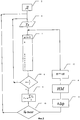
На фиг.1 показана схема соединения элементов системы регулирования линейной плотности волокнистого настила. На фиг.2 - блок схема способа регулирования.Figure 1 shows the connection diagram of the elements of the linear density control system of the fibrous flooring. Figure 2 is a block diagram of a control method.
Схема для осуществления способа включает объект управления (ОУ) 1, представляющий собой бункер чесальной машины с формируемым волокнистым настилом, датчик линейной плотности ленты (Д) 2, электронный блок (ЭБ) 3, исполнительный механизм (ИМ) 4, источник разрежения воздуха (ИРВ) 5, устройство ввода значений замера датчика 6, стек значений линейной плотности ленты 5, устройство ввода значений замера датчика 7, определитель количества значений линейной плотности ленты 8, определитель среднего значения линейной плотности ленты 9, определитель отклонения среднего значения линейной плотности ленты от номинального значения 10, определитель сигнала управления 11, определитель количества замеров датчика после срабатывания (ИМ) 12.The scheme for implementing the method includes a control object (OS) 1, which is a hopper of a carding machine with a fibrous flooring being formed, a linear linear density sensor (D) 2, an electronic unit (EB) 3, an actuator (IM) 4, an air rarefaction source (IRV) ) 5, a device for inputting values for measuring a
Способ реализуется следующим образом. Система транспортировки волокнистого материала подает его в бункер чесальной машины ОУ 1, который оснащен устройством для очистки волокнистого материала [2]. Источник разрежения воздуха 5 создает разрежение воздуха в пневмокамерах устройства, которое с помощью средства изменения направления воздушных потоков подводит его к перфорированным стенкам, расположенным на противоположных сторонах бункера. Попеременное просасывание волокнистого настила потоками воздуха с противоположных сторон бункера совместно с подпором воздуха в системе пневмотранспортировки волокнистого материала создают условия формирования слоя волокнистого материала определенной плотности и его продвижение по бункеру. Чем выше разрежение воздуха, создаваемое ИРВ 5, тем более плотный формируется волокнистый настил. В соответствии с изменениями линейной плотности настила в бункере изменяется и линейная плотность волокнистой ленты на выходе чесальной машины. Таким образом, при изменении степени разрежения воздуха с помощью ИРВ 5 устройство для очистки волокнистого материала [2] способно выполнять функцию регулирования линейной плотности волокнистого настила в бункере чесальной машины. Текущее значение линейной плотности ленты на выходе чесальной машины измеряется с помощью датчика 2. Промежуток времени между считыванием показателей датчика определяется по формуле:The method is implemented as follows. The fibrous material transportation system feeds it into the hopper of the
![]()
![]()
гдеWhere
l - ширина перфорированных стенок бункера, м;l is the width of the perforated walls of the hopper, m;
Е - вытяжка на чесальной машине;E - hood on a carding machine;
V - линейная скорость выпуска ленты, м/мин.V is the linear speed of the tape, m / min.
С помощью устройства ввода замеров датчика 6 текущее значение линейной плотности ленты Тф поступает в ЭБ 3. Каждое текущее значение Тф поступает в стек значений линейной плотности ленты 7, вытесняя одно значение. Количество замеров в стеке принимается в соответствии с условием (2).Using the input device of measurements of the
Выбор конкретного значения n из указанного диапазона позволяет изменять инерционность системы регулирования. Чем выше n, тем больше инерционность системы. Минимальное значение n соответствует отношению L к 1. Участок волокнистого настила длиной L и изменение разрежения воздуха уже не оказывают регулирующего воздействия на линейную плотность настила. Максимальное количество замеров датчика n соответствует количеству замеров линейной плотности ленты в течение смены. В этот период не изменяются такие факторы, как параметры микроклимата (температура, влажность), оказывающие влияние на линейную плотность волокнистого настила в бункере чесальной машины.The choice of a specific value of n from the specified range allows you to change the inertia of the control system. The higher n, the greater the inertia of the system. The minimum value of n corresponds to the ratio of L to 1. A section of fibrous flooring of length L and a change in the vacuum of air no longer have a regulatory effect on the linear density of the flooring. The maximum number of measurements of the sensor n corresponds to the number of measurements of the linear density of the tape during the shift. During this period, such factors as microclimate parameters (temperature, humidity) do not affect the linear density of the fibrous flooring in the hopper of the carding machine.
С помощью датчика 2 измеряется фактическое значение линейной плотности ленты Тф, которое устройством 6 помещает его в стек 7. При заполнении стека 7 необходимым количеством замеров, задаваемых определителем 8, происходит расчет среднего значения линейной плотности ленты ![]()
![]()
![]()
![]()
Оценка отклонения ![]()
![]()
![]()
![]()
После произведенной оценки возможны две ситуации:After the assessment, two situations are possible:
1 - фактическое отклонение меньше допустимого;1 - the actual deviation is less than permissible;
2 - фактическое отклонение больше или равно допустимому.2 - the actual deviation is greater than or equal to the permissible.
В первом случае система не генерирует сигнал управления на изменение разряжения воздуха, подаваемого к устройству [2], и через интервал времени τ происходит считывание следующего значения Тф, которое вытесняет в стеке одно начальное значение. Затем в текущем цикле рассчитывается значение ![]()
![]()
![]()
![]()
![]()
![]()
![]()
![]()
![]()
![]()
![]()
![]()
В том случае, когда ![]()
![]()
![]()
![]()
Источники информацииSources of information
1. А.С. №1266904 А1, “Устройство для регулирования линейной плотности волокнистого продукта на выходе бункерного питателя” / Ц.И.Калинин. Опубл. 30.10.86. Бюл. №40.1. A.S. No. 1266904 A1, “Device for controlling the linear density of the fibrous product at the output of the hopper feeder” / Ts.I. Kalinin. Publ. 10/30/86. Bull. Number 40.
2. Патент РФ №2078158, МПК D 01 G 9/06 “Устройство для очистки волокнистого материала” / Ю.П.Лебедев и др. Опубл. 27.04.97. Бюл. №12.2. RF patent No. 2078158, IPC D 01 G 9/06 “Device for cleaning fibrous material” / Yu.P. Lebedev and others Publ. 04/27/97. Bull. No. 12.
Claims (1)
Priority Applications (1)
| Application Number | Priority Date | Filing Date | Title |
|---|---|---|---|
| RU2002114033/12A RU2245403C2 (en) | 2002-05-29 | 2002-05-29 | Method to control a linear density of a fibrous floor in the loading pocket of the breaker |
Applications Claiming Priority (1)
| Application Number | Priority Date | Filing Date | Title |
|---|---|---|---|
| RU2002114033/12A RU2245403C2 (en) | 2002-05-29 | 2002-05-29 | Method to control a linear density of a fibrous floor in the loading pocket of the breaker |
Publications (2)
| Publication Number | Publication Date |
|---|---|
| RU2002114033A RU2002114033A (en) | 2003-11-20 |
| RU2245403C2 true RU2245403C2 (en) | 2005-01-27 |
Family
ID=35139236
Family Applications (1)
| Application Number | Title | Priority Date | Filing Date |
|---|---|---|---|
| RU2002114033/12A RU2245403C2 (en) | 2002-05-29 | 2002-05-29 | Method to control a linear density of a fibrous floor in the loading pocket of the breaker |
Country Status (1)
| Country | Link |
|---|---|
| RU (1) | RU2245403C2 (en) |
Cited By (1)
| Publication number | Priority date | Publication date | Assignee | Title |
|---|---|---|---|---|
| RU2321691C2 (en) * | 2005-07-04 | 2008-04-10 | Государственное общеобразовательное учреждение высшего профессионального Образования "Ивановский государственный университет" | Method for regulating linear density of fibrous covering and sliver on carding machine |
Citations (5)
| Publication number | Priority date | Publication date | Assignee | Title |
|---|---|---|---|---|
| US4181361A (en) * | 1974-08-13 | 1980-01-01 | Occidental Oil Shale, Inc. | Gas collection system for oil shale retort |
| GB1577689A (en) * | 1976-12-22 | 1980-10-29 | Truetzschler & Co | Process and apparatus for producing a continuous substantially uniform fibre web and apparatus for regulating the process |
| SU1171581A1 (en) * | 1983-06-13 | 1985-08-07 | Ивановский научно-исследовательский институт хлопчатобумажной промышленности | Apparatus for controlling linear density of fibrous product |
| SU1618792A1 (en) * | 1988-02-18 | 1991-01-07 | Центральный Научно-Исследовательский Институт Хлопкоочистительной Промышленности | Method of assessing cotton fibre quality |
| RU2078158C1 (en) * | 1995-05-12 | 1997-04-27 | Учебно-научно-производственный центр внедрения новых технологий | Apparatus for purification of fibrous material |
-
2002
- 2002-05-29 RU RU2002114033/12A patent/RU2245403C2/en not_active IP Right Cessation
Patent Citations (5)
| Publication number | Priority date | Publication date | Assignee | Title |
|---|---|---|---|---|
| US4181361A (en) * | 1974-08-13 | 1980-01-01 | Occidental Oil Shale, Inc. | Gas collection system for oil shale retort |
| GB1577689A (en) * | 1976-12-22 | 1980-10-29 | Truetzschler & Co | Process and apparatus for producing a continuous substantially uniform fibre web and apparatus for regulating the process |
| SU1171581A1 (en) * | 1983-06-13 | 1985-08-07 | Ивановский научно-исследовательский институт хлопчатобумажной промышленности | Apparatus for controlling linear density of fibrous product |
| SU1618792A1 (en) * | 1988-02-18 | 1991-01-07 | Центральный Научно-Исследовательский Институт Хлопкоочистительной Промышленности | Method of assessing cotton fibre quality |
| RU2078158C1 (en) * | 1995-05-12 | 1997-04-27 | Учебно-научно-производственный центр внедрения новых технологий | Apparatus for purification of fibrous material |
Cited By (1)
| Publication number | Priority date | Publication date | Assignee | Title |
|---|---|---|---|---|
| RU2321691C2 (en) * | 2005-07-04 | 2008-04-10 | Государственное общеобразовательное учреждение высшего профессионального Образования "Ивановский государственный университет" | Method for regulating linear density of fibrous covering and sliver on carding machine |
Similar Documents
| Publication | Publication Date | Title |
|---|---|---|
| CN104379822B (en) | Method and device for adjusting fiber feed to carding machine | |
| US20170342603A1 (en) | Method and device for loading an installation with fibres | |
| CN110318124B (en) | Feeding device for carding machines | |
| CN102209475A (en) | Device and method for feeding cut tobacco from a tobacco delivery unit to a tobacco processing machine | |
| US4876769A (en) | Regulation of processing stages of a fiber processing installation | |
| US4779311A (en) | Method and apparatus for feeding a plurality of textile fiber processing machines | |
| US20190240864A1 (en) | Method and apparatus for forming compacted powder products | |
| JPS6285034A (en) | Method and apparatus for supplying fiber material for spinning to opener or cleaner | |
| US4701981A (en) | Apparatus for pneumatically feeding a plurality of carding machines | |
| CN101560599B (en) | Thickness control method and control system of mixed material layer | |
| RU2245403C2 (en) | Method to control a linear density of a fibrous floor in the loading pocket of the breaker | |
| CN101096788A (en) | A drafting control method for a drafting system of a textile machine, and a textile machine | |
| US10793977B2 (en) | Pressure regulation in a flock feed | |
| CN102732420A (en) | Curved substrate feeding device in rotating disk solid culturing device and curved substrate feeding method in rotating disk solid culturing device | |
| GB2411907A (en) | Spinning preparation machine, for example a tuft feeder, having a feed device | |
| JPH0247312A (en) | Method and apparatus for manufacturing an uniform and continuous sliver | |
| JPS6385118A (en) | Method and apparatus for controlling web weight | |
| CN101449855A (en) | Rod forming device in a machine for the tobacco processing industry | |
| CN105716987A (en) | Sintered batch moisture detection and analysis device and analyzing method thereof | |
| US4353667A (en) | Method of and apparatus for maintaining substantially constant a quantity of opened fibrous material | |
| US20060168764A1 (en) | Spinning-mill preparing machine with a control apparatus | |
| RU2321691C2 (en) | Method for regulating linear density of fibrous covering and sliver on carding machine | |
| CA2496940C (en) | Controlling feeding of solid matter | |
| FI61328C (en) | FOERFARANDE FOER FOERBAETTRANDE AV JAEMNHETEN I YTVIKTEN HOS EN MINERALULLSMATTA | |
| CN205665131U (en) | Sintering cooperation material moisture detection and analysis device |
Legal Events
| Date | Code | Title | Description |
|---|---|---|---|
| MM4A | The patent is invalid due to non-payment of fees |
Effective date: 20050530 |