RU2230162C1 - Adjustable support structure - Google Patents
Adjustable support structure Download PDFInfo
- Publication number
- RU2230162C1 RU2230162C1 RU2003133178/03A RU2003133178A RU2230162C1 RU 2230162 C1 RU2230162 C1 RU 2230162C1 RU 2003133178/03 A RU2003133178/03 A RU 2003133178/03A RU 2003133178 A RU2003133178 A RU 2003133178A RU 2230162 C1 RU2230162 C1 RU 2230162C1
- Authority
- RU
- Russia
- Prior art keywords
- plate
- threaded rod
- slots
- tubular member
- upper plate
- Prior art date
Links
- 230000002093 peripheral effect Effects 0.000 claims abstract description 5
- 229930182670 Astin Natural products 0.000 claims 1
- 230000000694 effects Effects 0.000 abstract 1
- 239000000126 substance Substances 0.000 abstract 1
- 230000005540 biological transmission Effects 0.000 description 1
- 238000010276 construction Methods 0.000 description 1
- 238000009408 flooring Methods 0.000 description 1
- 238000004519 manufacturing process Methods 0.000 description 1
- 238000003466 welding Methods 0.000 description 1
Images


Landscapes
- Floor Finish (AREA)
Abstract
Description
Изобретение относится к строительству, в частности к регулируемым опорным конструкциям, предназначенным преимущественно для опирания на требуемой высоте балок или настила фальшпола в помещениях, где требуется обеспечить доступ в подпольное пространство.The invention relates to construction, in particular to adjustable supporting structures, designed primarily to support the beams or raised flooring at the required height in rooms where access to the underground space is required.
Наиболее близким аналогом к изобретению является регулируемая опорная конструкция, включающая нижнюю пластину, резьбовую стойку с гайкой, одним концом соединенную с верхней пластиной, снабженной по ее периметру крестообразно расположенными парами прорезей, открытых с периферийной части пластины, и размещенными между смежными прорезями отверстиями под крепежные элементы (ЕР 0362718, кл. Е 04 F 15/024, 1990).The closest analogue to the invention is an adjustable support structure, including a lower plate, a threaded stand with a nut, one end connected to the upper plate, provided along its perimeter with crosswise arranged pairs of slots open from the peripheral part of the plate, and holes for fasteners placed between adjacent slots (EP 0362718, CL E 04 F 15/024, 1990).
В известном решении верхняя пластина выполнена в виде плоского кольца с установленной на нем опорной прокладкой, перекрывающей внутренний диаметр кольца, что приводит к дополнительным трудозатратам при изготовлении конструкции опоры.In a known solution, the upper plate is made in the form of a flat ring with a support gasket installed on it, overlapping the inner diameter of the ring, which leads to additional labor costs in the manufacture of the support structure.
Технической задачей изобретения является создание регулируемой опоры с верхней пластиной, обладающей несущей способностью без установки на нее дополнительных элементов.An object of the invention is the creation of an adjustable support with an upper plate having a bearing capacity without installing additional elements on it.
Данная задача решается за счет того, что в регулируемой опорной конструкции, включающей нижнюю пластину, резьбовую стойку с гайкой, одним концом соединенную с верхней пластиной, снабженной по ее периметру крестообразно расположенными парами прорезей, открытых с периферийной части пластины, и размещенными между смежными прорезями отверстиями под крепежные элементы, верхняя пластина выполнена в виде диска, свободный конец резьбового стержня установлен с возможностью осевого перемещения в полость трубчатого элемента, соединенного с прямоугольной нижней пластиной, нижняя и верхняя пластины выполнены с центральным отверстием для размещения в нем с последующим жестким соединением с пластинами концов соответственно трубчатого элемента и резьбового стержня и расположенной вокруг отверстия выемкой, глубина которой не превышает толщину пластины, при этом выпуклые поверхности выемок верхней и нижней пластин обращены навстречу друг другу, резьбовой стержень снабжен контргайкой, фиксирующей положение верхней плиты относительно нижней, а расстояние между оппозитно расположенными прорезями, продольные оси которых лежат на одной прямой, не превышает 2/3 диаметра диска.This problem is solved due to the fact that in an adjustable supporting structure, including the lower plate, a threaded stand with a nut, one end connected to the upper plate, provided along its perimeter with crosswise arranged pairs of slots open from the peripheral part of the plate, and holes located between adjacent slots under the fasteners, the upper plate is made in the form of a disk, the free end of the threaded rod is mounted with the possibility of axial movement in the cavity of the tubular element connected to with an angular lower plate, the lower and upper plates are made with a central hole for placement in it, followed by rigid connection with the plates of the ends of the tubular element and the threaded rod, respectively, and a recess located around the hole, the depth of which does not exceed the thickness of the plate, while the convex surfaces of the recesses of the upper and lower the plates face each other, the threaded rod is equipped with a lock nut, fixing the position of the upper plate relative to the lower, and the distance between the opposite is ennymi slots, the longitudinal axes of which lie on one line, not greater than 2/3 of the disc diameter.
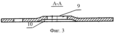
На фиг.1 изображен разрез регулируемой конструкции; на фиг.2 - план нижней пластины; на фиг.3 - разрез по А-А на фиг.2; на фиг.4 - план верхней пластины; на фиг.5 - разрез В-В на фиг.4.Figure 1 shows a section of an adjustable design; figure 2 is a plan of the lower plate; figure 3 is a section along aa in figure 2; figure 4 is a plan of the upper plate; figure 5 - section bb in figure 4.
Регулируемая опорная пластина включает нижнюю прямоугольную, преимущественно квадратную, пластину 1 с крепежными отверстиями 2, резьбовой стержень 3, взаимодействующий с регулировочной гайкой 4, и верхнюю пластину 5, выполненную в виде плоского диска.Adjustable support plate includes a lower rectangular, mainly square,
Верхняя пластина 5 по периметру снабжена крестообразно расположенными парами прорезей 6, открытых с периферийной части диска.The upper plate 5 around the perimeter is equipped with crosswise arranged pairs of
Между смежными прорезями на равноудаленном расстоянии от центра пластины под углом 45° расположены отверстия 7 для крепежных элементов.Between adjacent slots at an equidistant distance from the center of the plate at an angle of 45 ° are
Прорези предназначаются преимущественно для размещения в них боковых стенок балок.The slots are intended primarily for placement in them of the side walls of the beams.
В связи с тем что участки диска между прорезями являются наиболее нагруженными, длина прорезей должна быть достаточной для обеспечения несущей способности верхней пластины. В предлагаемом решении расстояние между прорезями В, продольные оси которых лежат на одной прямой, не должно превышать 2/3 диаметра D диска.Due to the fact that the sections of the disk between the slots are the most loaded, the length of the slots should be sufficient to ensure the bearing capacity of the upper plate. In the proposed solution, the distance between the slots B, the longitudinal axes of which lie on one straight line, should not exceed 2/3 of the diameter D of the disk.
Свободный конец резьбового стержня 3 установлен с возможностью его осевого перемещения в полости трубчатого элемента 8.The free end of the threaded rod 3 is installed with the possibility of axial movement in the cavity of the tubular element 8.
Нижняя пластина 1 и верхняя пластина 5 выполнены с центральным отверстием 9 для размещения в них концов соответственно трубчатого элемента 8 и резьбового стержня 3 с последующим их жестким соединением с пластиной посредством сварки.The
Центральное отверстие 9 в каждой пластине окружено выемкой 10, которая повышает жесткость пластины и исключает передачу вертикальной нагрузки на наиболее напряженную ее область.The
Выемка изготовлена методом штамповки и ее глубина не превышает толщину пластины δ.The recess is made by stamping and its depth does not exceed the thickness of the plate δ.
Выпуклые поверхности выемок нижней и верхней пластин обращены навстречу друг другу.The convex surfaces of the recesses of the lower and upper plates are facing towards each other.
Для фиксации положения верхней пластины относительно нижней резьбовой стержень снабжен контргайкой 11.To fix the position of the upper plate relative to the lower threaded rod is equipped with a lock nut 11.
Claims (1)
Priority Applications (1)
| Application Number | Priority Date | Filing Date | Title |
|---|---|---|---|
| RU2003133178/03A RU2230162C1 (en) | 2003-11-14 | 2003-11-14 | Adjustable support structure |
Applications Claiming Priority (1)
| Application Number | Priority Date | Filing Date | Title |
|---|---|---|---|
| RU2003133178/03A RU2230162C1 (en) | 2003-11-14 | 2003-11-14 | Adjustable support structure |
Publications (1)
| Publication Number | Publication Date |
|---|---|
| RU2230162C1 true RU2230162C1 (en) | 2004-06-10 |
Family
ID=32847127
Family Applications (1)
| Application Number | Title | Priority Date | Filing Date |
|---|---|---|---|
| RU2003133178/03A RU2230162C1 (en) | 2003-11-14 | 2003-11-14 | Adjustable support structure |
Country Status (1)
| Country | Link |
|---|---|
| RU (1) | RU2230162C1 (en) |
Cited By (6)
| Publication number | Priority date | Publication date | Assignee | Title |
|---|---|---|---|---|
| RU2278226C1 (en) * | 2005-03-14 | 2006-06-20 | Сергей Николаевич Кардашев | Adjustable metal support, for instance for false floor |
| RU2278227C1 (en) * | 2005-03-14 | 2006-06-20 | Сергей Николаевич Кардашев | Adjustable metal support, for instance for false floor |
| RU2278225C1 (en) * | 2005-03-14 | 2006-06-20 | Сергей Николаевич Кардашев | Adjustable metal support, for instance for false floor |
| RU2285776C1 (en) * | 2005-06-07 | 2006-10-20 | Сергей Николаевич Кардашев | Collapsible adjustable false floor support |
| RU2451162C1 (en) * | 2011-03-21 | 2012-05-20 | Общество с ограниченной ответственностью "Русская электротехническая компания" ("РУСЭЛКОМ") | Filter for hydraulic downhole motor |
| RU219695U1 (en) * | 2023-04-18 | 2023-08-01 | Пётр Владимирович КОЛЕСНИК | HEIGHT ADJUSTABLE FOUNDATION UNIT |
Citations (4)
| Publication number | Priority date | Publication date | Assignee | Title |
|---|---|---|---|---|
| US3616584A (en) * | 1970-01-06 | 1971-11-02 | Liskey Aluminum | Elevated floor assembly |
| US4685258A (en) * | 1984-12-05 | 1987-08-11 | Alcol, Ltd. | Access flooring system with increased load capacity |
| EP0362718A1 (en) * | 1988-10-05 | 1990-04-11 | MERO-Werke Dr.-Ing. Max Mengeringhausen GmbH & Co. | Grid bar for sectional false floors |
| RU29318U1 (en) * | 2003-01-21 | 2003-05-10 | Демиденко Владимир Иванович | ADJUSTABLE REGARDING THE BASIS OF FLOORS |
-
2003
- 2003-11-14 RU RU2003133178/03A patent/RU2230162C1/en not_active IP Right Cessation
Patent Citations (4)
| Publication number | Priority date | Publication date | Assignee | Title |
|---|---|---|---|---|
| US3616584A (en) * | 1970-01-06 | 1971-11-02 | Liskey Aluminum | Elevated floor assembly |
| US4685258A (en) * | 1984-12-05 | 1987-08-11 | Alcol, Ltd. | Access flooring system with increased load capacity |
| EP0362718A1 (en) * | 1988-10-05 | 1990-04-11 | MERO-Werke Dr.-Ing. Max Mengeringhausen GmbH & Co. | Grid bar for sectional false floors |
| RU29318U1 (en) * | 2003-01-21 | 2003-05-10 | Демиденко Владимир Иванович | ADJUSTABLE REGARDING THE BASIS OF FLOORS |
Cited By (6)
| Publication number | Priority date | Publication date | Assignee | Title |
|---|---|---|---|---|
| RU2278226C1 (en) * | 2005-03-14 | 2006-06-20 | Сергей Николаевич Кардашев | Adjustable metal support, for instance for false floor |
| RU2278227C1 (en) * | 2005-03-14 | 2006-06-20 | Сергей Николаевич Кардашев | Adjustable metal support, for instance for false floor |
| RU2278225C1 (en) * | 2005-03-14 | 2006-06-20 | Сергей Николаевич Кардашев | Adjustable metal support, for instance for false floor |
| RU2285776C1 (en) * | 2005-06-07 | 2006-10-20 | Сергей Николаевич Кардашев | Collapsible adjustable false floor support |
| RU2451162C1 (en) * | 2011-03-21 | 2012-05-20 | Общество с ограниченной ответственностью "Русская электротехническая компания" ("РУСЭЛКОМ") | Filter for hydraulic downhole motor |
| RU219695U1 (en) * | 2023-04-18 | 2023-08-01 | Пётр Владимирович КОЛЕСНИК | HEIGHT ADJUSTABLE FOUNDATION UNIT |
Similar Documents
| Publication | Publication Date | Title |
|---|---|---|
| US8015760B2 (en) | Seismic isolation access floor assembly | |
| US5904009A (en) | Shock-resistant floor-supporting strut unit which can bear a heavy load thereon | |
| CA1338371E (en) | Construction Device for Connecting Building Elements | |
| US8950133B2 (en) | Bracket and an arrangement for supporting a precast slab element of concrete on a precast structure element of concrete | |
| EP0784137B1 (en) | Apparatus and method for protecting buildings from earthquakes | |
| US6397535B1 (en) | Height-adjustable concrete mold supporting system and method for constructing concrete building | |
| KR101499111B1 (en) | Hybrid Foundation For Water Tank | |
| RU2230162C1 (en) | Adjustable support structure | |
| KR20170094822A (en) | Below bridge support having variable anchor socket | |
| EP2322739B1 (en) | Support for raised flooring elements, and raised flooring assembly comprising such support | |
| JP6798833B2 (en) | How to fix building support structure and uneven settlement of buildings | |
| JP7406225B2 (en) | Assembly structure and method for manufacturing the assembly structure | |
| RU38478U1 (en) | COMPONENT KIT AND ADJUSTABLE SUPPORT STRUCTURE FOR ADJUSTABLE FLOOR | |
| KR100840624B1 (en) | Posts for fence | |
| JP4899210B2 (en) | Sliding bearing and its mounting method and seismic isolation structure | |
| JP5486158B2 (en) | Double floor support legs and double floor structure | |
| JP6991295B2 (en) | How to fix building support structure and uneven settlement of buildings | |
| JP3818408B2 (en) | Structure of base-isolated floor bearings and extension bearing members for base-isolated floor bearings | |
| RU52892U1 (en) | ADJUSTABLE BRACKET | |
| JP7385815B2 (en) | hanging frame | |
| KR100657592B1 (en) | Modular architecture | |
| RU52893U1 (en) | ADJUSTABLE BRACKET | |
| JP2811194B2 (en) | Residential pedestal equipment | |
| RU46792U1 (en) | ADJUSTABLE METAL SUPPORT, PREVIOUSLY FOR FALSE FLOOR | |
| RU2268973C1 (en) | Adjustable building structure support |
Legal Events
| Date | Code | Title | Description |
|---|---|---|---|
| QB4A | Licence on use of patent |
Effective date: 20061026 |
|
| MM4A | The patent is invalid due to non-payment of fees |
Effective date: 20111115 |
|
| NF4A | Reinstatement of patent |
Effective date: 20160620 |
|
| MM4A | The patent is invalid due to non-payment of fees |
Effective date: 20171115 |