RU2210972C1 - Device for carrying out screening vision function diagnosis - Google Patents
Device for carrying out screening vision function diagnosis Download PDFInfo
- Publication number
- RU2210972C1 RU2210972C1 RU2001134563/14A RU2001134563A RU2210972C1 RU 2210972 C1 RU2210972 C1 RU 2210972C1 RU 2001134563/14 A RU2001134563/14 A RU 2001134563/14A RU 2001134563 A RU2001134563 A RU 2001134563A RU 2210972 C1 RU2210972 C1 RU 2210972C1
- Authority
- RU
- Russia
- Prior art keywords
- unit
- output
- input
- block
- inputs
- Prior art date
Links
- 238000012216 screening Methods 0.000 title claims abstract description 118
- 230000004438 eyesight Effects 0.000 title claims description 42
- 238000003745 diagnosis Methods 0.000 title description 5
- 238000012360 testing method Methods 0.000 claims abstract description 237
- 238000012545 processing Methods 0.000 claims abstract description 28
- 201000009310 astigmatism Diseases 0.000 claims description 125
- 230000015572 biosynthetic process Effects 0.000 claims description 91
- 239000012634 fragment Substances 0.000 claims description 56
- 230000004044 response Effects 0.000 claims description 55
- 238000004458 analytical method Methods 0.000 claims description 51
- 239000000203 mixture Substances 0.000 claims description 45
- 238000006073 displacement reaction Methods 0.000 claims description 42
- 230000004304 visual acuity Effects 0.000 claims description 38
- 238000001514 detection method Methods 0.000 claims description 32
- 238000006243 chemical reaction Methods 0.000 claims description 29
- 201000011573 Aniseikonia Diseases 0.000 claims description 26
- 238000009825 accumulation Methods 0.000 claims description 26
- 238000004737 colorimetric analysis Methods 0.000 claims description 25
- 239000003550 marker Substances 0.000 claims description 24
- 230000003287 optical effect Effects 0.000 claims description 24
- 230000004927 fusion Effects 0.000 claims description 20
- 238000013500 data storage Methods 0.000 claims description 19
- 208000004350 Strabismus Diseases 0.000 claims description 18
- 238000009434 installation Methods 0.000 claims description 14
- 239000003086 colorant Substances 0.000 claims description 12
- 238000011160 research Methods 0.000 claims description 11
- 210000001525 retina Anatomy 0.000 claims description 6
- 230000002207 retinal effect Effects 0.000 claims description 6
- 238000011156 evaluation Methods 0.000 claims description 5
- 238000005286 illumination Methods 0.000 claims description 5
- 238000012986 modification Methods 0.000 claims description 5
- 230000004048 modification Effects 0.000 claims description 5
- 238000003860 storage Methods 0.000 claims description 3
- 238000002156 mixing Methods 0.000 claims description 2
- 238000007726 management method Methods 0.000 claims 1
- 238000000196 viscometry Methods 0.000 claims 1
- 230000000694 effects Effects 0.000 abstract description 2
- 239000000126 substance Substances 0.000 abstract 1
- 238000000034 method Methods 0.000 description 34
- 230000008569 process Effects 0.000 description 19
- 238000003825 pressing Methods 0.000 description 11
- 230000007704 transition Effects 0.000 description 8
- 238000012937 correction Methods 0.000 description 7
- 230000000007 visual effect Effects 0.000 description 7
- 239000011159 matrix material Substances 0.000 description 6
- 230000006870 function Effects 0.000 description 5
- 206010047571 Visual impairment Diseases 0.000 description 4
- 230000003111 delayed effect Effects 0.000 description 4
- 208000037265 diseases, disorders, signs and symptoms Diseases 0.000 description 4
- 230000035807 sensation Effects 0.000 description 4
- 230000035945 sensitivity Effects 0.000 description 4
- 230000004382 visual function Effects 0.000 description 4
- 230000008859 change Effects 0.000 description 3
- 230000004456 color vision Effects 0.000 description 3
- 230000007547 defect Effects 0.000 description 3
- 238000000926 separation method Methods 0.000 description 3
- 230000003068 static effect Effects 0.000 description 3
- 230000016776 visual perception Effects 0.000 description 3
- 208000029091 Refraction disease Diseases 0.000 description 2
- 230000002159 abnormal effect Effects 0.000 description 2
- 230000004430 ametropia Effects 0.000 description 2
- 238000010586 diagram Methods 0.000 description 2
- 201000010099 disease Diseases 0.000 description 2
- 208000035475 disorder Diseases 0.000 description 2
- 238000009826 distribution Methods 0.000 description 2
- 239000011521 glass Substances 0.000 description 2
- 210000003205 muscle Anatomy 0.000 description 2
- 210000000056 organ Anatomy 0.000 description 2
- 230000007170 pathology Effects 0.000 description 2
- 238000012797 qualification Methods 0.000 description 2
- 230000035484 reaction time Effects 0.000 description 2
- 208000014733 refractive error Diseases 0.000 description 2
- 238000012422 test repetition Methods 0.000 description 2
- 208000029257 vision disease Diseases 0.000 description 2
- 230000004393 visual impairment Effects 0.000 description 2
- 206010003694 Atrophy Diseases 0.000 description 1
- 208000006992 Color Vision Defects Diseases 0.000 description 1
- 208000010415 Low Vision Diseases 0.000 description 1
- 102000010410 Nogo Proteins Human genes 0.000 description 1
- 108010077641 Nogo Proteins Proteins 0.000 description 1
- 241001290864 Schoenoplectus Species 0.000 description 1
- 206010047555 Visual field defect Diseases 0.000 description 1
- 201000000314 abnormal retinal correspondence Diseases 0.000 description 1
- 230000004075 alteration Effects 0.000 description 1
- 238000013473 artificial intelligence Methods 0.000 description 1
- 230000037444 atrophy Effects 0.000 description 1
- 230000006399 behavior Effects 0.000 description 1
- 230000008901 benefit Effects 0.000 description 1
- 238000009414 blockwork Methods 0.000 description 1
- 238000009395 breeding Methods 0.000 description 1
- 230000001488 breeding effect Effects 0.000 description 1
- 238000005352 clarification Methods 0.000 description 1
- 201000007254 color blindness Diseases 0.000 description 1
- 238000004891 communication Methods 0.000 description 1
- 230000000295 complement effect Effects 0.000 description 1
- 230000006378 damage Effects 0.000 description 1
- 230000006735 deficit Effects 0.000 description 1
- 230000007850 degeneration Effects 0.000 description 1
- 238000011161 development Methods 0.000 description 1
- 230000007613 environmental effect Effects 0.000 description 1
- 230000005284 excitation Effects 0.000 description 1
- 238000013467 fragmentation Methods 0.000 description 1
- 238000006062 fragmentation reaction Methods 0.000 description 1
- 210000003128 head Anatomy 0.000 description 1
- 230000036541 health Effects 0.000 description 1
- 238000003384 imaging method Methods 0.000 description 1
- 230000003993 interaction Effects 0.000 description 1
- 230000002452 interceptive effect Effects 0.000 description 1
- 230000035987 intoxication Effects 0.000 description 1
- 231100000566 intoxication Toxicity 0.000 description 1
- 230000004303 low vision Effects 0.000 description 1
- 238000012423 maintenance Methods 0.000 description 1
- 230000007246 mechanism Effects 0.000 description 1
- 238000012544 monitoring process Methods 0.000 description 1
- 230000035772 mutation Effects 0.000 description 1
- 230000008520 organization Effects 0.000 description 1
- 230000001575 pathological effect Effects 0.000 description 1
- 230000035778 pathophysiological process Effects 0.000 description 1
- 238000002360 preparation method Methods 0.000 description 1
- 238000004321 preservation Methods 0.000 description 1
- 230000003449 preventive effect Effects 0.000 description 1
- 238000004088 simulation Methods 0.000 description 1
- 239000007787 solid Substances 0.000 description 1
- 238000010998 test method Methods 0.000 description 1
- 230000001225 therapeutic effect Effects 0.000 description 1
- 238000012795 verification Methods 0.000 description 1
- 238000012800 visualization Methods 0.000 description 1
Images




Landscapes
- Eye Examination Apparatus (AREA)
Abstract
Description
Изобретение относится к офтальмологии и может использоваться для скрининговой (доврачебной) диагностики зрения. The invention relates to ophthalmology and can be used for screening (pre-medical) diagnosis of vision.
Перенесенные заболевания, травмы, интоксикации, различные экологические воздействия приводят к мутациям, дистрофиям, дегенерациям, атрофиям и прочим патофизиологическим процессам, влекущим за собой нарушение или полную утрату зрительных функций и снижение работоспособности. Необходимость выявления подобных зрительных нарушений на ранних стадиях их возникновения для выработки адекватных, патогенетически обоснованных лечебных мероприятий не вызывает сомнений. Однако существующая сеть специализированных офтальмологических учреждений, как и всякая система массового обслуживания, имеет ограниченную пропускную способность и рассчитана на определенный поток "заявок". При этом молчаливо предполагается, что система обслуживает больных, и человек обратится к врачу лишь тогда, когда заметит определенные дефекты в собственном здоровье. Но в том-то и дело, что один обратится к офтальмологу при ничтожных признаках нарушения зрения, а другой - при серьезных нарушениях, когда процесс уже в значительной степени запущен. Past diseases, injuries, intoxications, various environmental influences lead to mutations, dystrophies, degenerations, atrophies and other pathophysiological processes that entail a violation or complete loss of visual function and reduced performance. The need to identify such visual disturbances in the early stages of their occurrence in order to develop adequate, pathogenetically substantiated therapeutic measures is beyond doubt. However, the existing network of specialized ophthalmological institutions, like any queuing system, has limited bandwidth and is designed for a certain stream of “applications”. At the same time, it is tacitly assumed that the system serves patients, and a person will see a doctor only when he sees certain defects in his own health. But the fact of the matter is that one will turn to an ophthalmologist for insignificant signs of visual impairment, and the other for serious impairments, when the process is already largely launched.
Для повышения производительности системы можно использовать средства автоматизации рутинных операций. To improve system performance, you can use automation tools for routine operations.
Не претендуя на столь радикальное решение проблемы, авторы предлагаемого изобретения рассматривают медицинскую диагностику как двухэтапную процедуру обслуживания. Первый этап - скрининг - включает достаточно формальную процедуру проверки наличия или отсутствия нарушений зрительных функций. Второй этап предполагает содержательный анализ причин выявленных нарушений для выбора адекватных мероприятий их устранения. Первый этап может выполняться персоналом средней степени квалификации с использованием автоматизированных средств, второй требует глубоких знаний квалифицированного специалиста. Without claiming to be such a radical solution to the problem, the authors of the invention consider medical diagnostics as a two-stage maintenance procedure. The first stage - screening - includes a fairly formal procedure for checking the presence or absence of visual impairment. The second stage involves a meaningful analysis of the causes of identified violations to select adequate measures to address them. The first stage can be performed by medium-skilled personnel using automated tools, the second requires in-depth knowledge of a qualified specialist.
Среди методик функциональных исследований органа зрения, позволяющих адекватно оценивать зрительное восприятие и качество переработки зрительной информации, основное место занимают психофизические методы. При проведении подобных исследований пациент рассматривается как некий "черный ящик": стимул на входе - реакция на выходе. Неадекватность реакции предъявленному стимулу свидетельствует о нарушении исследуемой функции зрения. Among the methods of functional research of the organ of vision, allowing to adequately assess visual perception and the quality of processing of visual information, the main place is occupied by psychophysical methods. When conducting such studies, the patient is regarded as a kind of "black box": a stimulus at the entrance - a reaction at the exit. The inadequacy of the reaction to the presented stimulus indicates a violation of the studied function of vision.
Основными принятыми в офтальмологической практике методиками функциональных исследований оценки зрительного восприятия являются: визометрия, связанная с оценкой остроты зрения; визоконтрастометрия, связанная с оценкой контрастной чувствительности; цветометрия, связанная с выявлением дефектов цветового восприятия; бинокулометрия, связанная с исследованием состояния функций бинокулярного зрения; периметрия, связанная с выявлением дефектов поля зрения; рефрактометрия, связанная с исследованием рефракции оптической системы глаза; "астигмометрия", связанная с исследованием одного из дефектов преломляющей среды глаза - астигматизма. The main methods of functional research adopted in ophthalmic practice for assessing visual perception are: visometry associated with the assessment of visual acuity; visocontrastometry associated with the assessment of contrast sensitivity; colorimetry associated with the identification of defects in color perception; binoculometry associated with the study of the state of binocular vision functions; perimetry associated with the detection of visual field defects; refractometry associated with the study of refraction of the optical system of the eye; "astigmometry" associated with the study of one of the defects in the refractive medium of the eye - astigmatism.
Известно значительное количество различных средств для проведения указанных функциональных исследований - от простых таблиц (Головина - Сивцева, используемых в визометрии, или Волкова - Юстовой - в цветометрии), до сложных и дорогих приборов, таких как рефрактометр или периметр. Все они обладают узкими функциональными возможностями (количественная или качественная оценка какой-то одной зрительной функции), низкой оперативностью или высокой стоимостью. A significant number of different tools are known for carrying out the indicated functional studies - from simple tables (Golovin - Sivtsev used in visometry, or Volkov - Yustova - in colorimetry), to complex and expensive instruments, such as a refractometer or perimeter. All of them have narrow functional capabilities (quantitative or qualitative assessment of any one visual function), low efficiency or high cost.
Устройства типа периметра управляются персональным компьютером, поэтому формирование стимула, регистрация реакции пациента и ее интерпретация осуществляется автоматически, но для предъявления стимула используется сложное устройство визуализации и стоимость прибора достигает десятков тысяч германских марок. Кроме того, номенклатура используемых стимулов ограничивается только задачей периметрии. Perimeter-type devices are controlled by a personal computer, therefore, the formation of a stimulus, registration of a patient’s reaction and its interpretation is carried out automatically, but a complex visualization device is used to present the stimulus and the cost of the device reaches tens of thousands of German marks. In addition, the nomenclature of the stimuli used is limited only by the perimetry task.
Более универсальными являются различные проекторы знаков, включающие блок формирования оптотипов, например, в виде кассеты со слайдами, блок отображения в виде проектора и блок дистанционного управления [1]. More versatile are various sign projectors, including an optotype development unit, for example, in the form of a cassette with slides, a display unit in the form of a projector and a remote control unit [1].
Это устройство выбрано в качестве прототипа. Оперативность по сравнению с использованием таблиц повышается за счет дистанционного управления предъявлением тестов, но остается низкой, поскольку регистрация и интерпретация ощущений пациента осуществляется в процессе диалога пациента и оптометриста, что, к тому же, предполагает определенную квалификацию последнего. Еще одним существенным недостатком подобного устройства является принципиальная возможность предъявления только статических стимулов, типа таблиц для визометрии или теста Уорса для бинокулометрии. Статические изображения в виде таблицы знаков легко запоминаются испытуемым, что снижает достоверность при проведении повторных испытаний. This device is selected as a prototype. Efficiency in comparison with the use of tables is increased due to the remote control of the presentation of tests, but remains low, since the registration and interpretation of the patient's sensations is carried out in the process of dialogue between the patient and the optometrist, which, in addition, presupposes a certain qualification of the latter. Another significant drawback of such a device is the fundamental possibility of presenting only static stimuli, such as tables for visometry or the Wors test for binoculometry. Static images in the form of a table of characters are easily remembered by the subjects, which reduces reliability during repeated trials.
Технической задачей данного изобретения является разработка устройства для скрининговой диагностики зрения, осуществляющего по заранее заданной программе автоматическое формирование и предъявление испытуемому офтальмологических тестов для диагностики нарушений различных функций зрения, автоматическую регистрацию ощущений пациента в процессе человеко-машинного диалога, их интерпретацию, формирование отчета в виде предварительного заключения, сохранение результатов в базе данных, их отображение на экране монитора и/или бумажном носителе, при этом в зависимости от особенностей конкретной диагностической задачи формируются и используются различные программы скрининга. The technical task of this invention is to develop a device for screening diagnostics of vision, which, according to a predetermined program, automatically generates and presents the subject with ophthalmological tests for the diagnosis of disorders of various vision functions, automatically registers the patient's sensations in the process of human-machine dialogue, interprets them, and generates a report in the form of preliminary conclusions, storing results in a database, their display on a monitor screen and / or paper ositele, while depending on the characteristics of a specific diagnostic task formed and used various screening programs.
Поставленная задача решается в устройстве для скрининговой диагностики зрения, включающем первый блок управления, блок формирования офтальмологических тестов и блок регистрации данных скрининга, в которое согласно изобретению введены первый и второй блоки ввода команд, блок формирования программ скрининга, блок выбора программ скрининга, блок регистрации пациента, первый блок памяти, первый и второй буферные блоки памяти и блок ввода данных поиска, а блок регистрации данных скрининга содержит второй блок памяти, второй блок управления, блок обработки данных скрининга и формирования заключения, первый блок ИЛИ, принтер, видеоадаптер и блок отображения, при этом выходы первого и второго блоков ввода команд соединены соответственно с первым и вторым входами первого блока управления, первый выход которого соединен через блок регистрации данных пациента с первым входом блока формирования офтальмологических тестов, второй выход - через блок формирования программ скрининга, первый блок памяти, первый буферный блок памяти соединен с первым входом второго буферного блока памяти, третий выход - через блок выбора программ скрининга с вторым входом первого блока памяти, второй и третий выходы блока регистрации данных пациента соединены с вторыми входами соответственно первого и второго буферных блоков памяти, выход последнего из которых соединен с вторым входом блока формирования офтальмологических тестов, третий вход которого подключен к четвертому выходу первого блока управления, первый выход - соединен с первым входом первого блока ИЛИ, а его второй выход - с первым входом второго блока управления, первый выход которого подключен к первому входу блока обработки данных скрининга и формирования заключения, второй вход и второй выход - соединены соответственно с выходом и входом второго блока памяти, а третий вход - через блок ввода данных поиска с пятым выходом первого блока управления, шестой выход которого соединен с вторым входом блока обработки данных скрининга и формирования заключения, первый выход которого подключен к принтеру, а второй выход - к второму входу первого блока ИЛИ, соединенному с входом блока отображения через видеоадаптер, второй выход которого подключен к третьему входу первого буферного блока памяти. The problem is solved in a device for screening diagnostics of vision, including a first control unit, an ophthalmological test generation unit and a screening data recording unit, into which according to the invention the first and second command input units, a screening program generating unit, a screening program selection unit, a patient registration unit are entered , the first memory unit, the first and second buffer memory units and the search data input unit, and the screening data recording unit comprises a second memory unit, a second control unit , a screening and generating a data processing unit, a first OR unit, a printer, a video adapter, and a display unit, wherein the outputs of the first and second command input units are connected respectively to the first and second inputs of the first control unit, the first output of which is connected through the patient data recording unit to the first input of the ophthalmological test forming unit, the second output through the screening program generating unit, the first memory unit, the first buffer memory unit is connected to the first input of the second buffer unit pa memory, the third output is through a screening program selection unit with a second input of the first memory unit, the second and third outputs of the patient data recording unit are connected to the second inputs of the first and second buffer memory units, the output of the last of which is connected to the second input of the ophthalmological test formation unit, the third input of which is connected to the fourth output of the first control unit, the first output is connected to the first input of the first OR block, and its second output is connected to the first input of the second control unit, the first the output of which is connected to the first input of the screening and processing data processing unit, the second input and the second output are connected respectively to the output and input of the second memory unit, and the third input is through the search data input unit with the fifth output of the first control unit, the sixth output of which is connected with the second input of the screening and processing data processing unit, the first output of which is connected to the printer, and the second output is to the second input of the first OR block, connected to the input of the display unit through the video adapter p, the second output of which is connected to the third input of the first buffer memory block.
Блок формирования офтальмологических тестов может содержать блок диспетчера тестов скрининга, третий буферный блок памяти, блок визометрии, блок визоконтрастометрии, блок цветометрии, блок бинокулометрии, блок кампиметрии, блок анализа астигматизма, второй блок ИЛИ и блок накопления и вывода результатов скрининга. The ophthalmological test generation unit may include a screening test dispatcher unit, a third buffer memory unit, a visometry unit, a visocontrastometry unit, a colorimetry unit, a binoculometry unit, a campimetry unit, an astigmatism analysis unit, a second OR unit, and a screening results accumulation and output unit.
Блок формирования программ скрининга может содержать блок выбора состава тестов скрининга, блок выбора последовательности тестов, блок выбора условий тестирования и блок валидатора. The screening program generation unit may comprise a screening test composition selection unit, a test sequence selection unit, a test conditions selection unit, and a validator unit.
Блок обработки данных скрининга и формирования заключения может содержать четвертый буферный блок памяти, первый блок сравнения, блок логического вывода, блок формирования отчета и блок формирования печатного отчета, первый счетчик, блок памяти эталонных данных тестов и блок памяти правил логического вывода. The screening and conclusion generation data processing unit may comprise a fourth buffer memory unit, a first comparison unit, an inference unit, a report generation unit and a printed report generation unit, a first counter, a test reference data memory unit and an inference rule memory unit.
Блок визометрии может содержать блок диспетчера тестов визометрии, пятый буферный блок памяти, блок определения остроты зрения, блок определения оптической установки глаза, третий блок ИЛИ и блок накопления и вывода результатов визометрии. The visometry unit may comprise a visometry test manager unit, a fifth memory buffer unit, a visual acuity determination unit, an optical eye determination unit, a third OR unit, and a visometry results storage and output unit.
Блок визоконтрастометрии может содержать третий блок управления, первый блок формирования изояркостного изображения, блок яркостной модуляции и первый блок композиции, второй блок формирования изояркостного изображения и первый блок смешения изображения, датчик пространственных частот, второй счетчик, первый блок интерпретации реакции пациента и первый датчик вертикального смещения, а также блок формирования видеограммы. The visocontrastometry unit may comprise a third control unit, a first block of iso-brightness image formation, a brightness modulation unit and a first composition block, a second iso-brightness image formation unit and a first image mixing unit, a spatial frequency sensor, a second counter, a first patient response interpretation unit and a first vertical displacement sensor , as well as a block for forming a videogram.
Блок цветометрии может содержать четвертый блок управления, первый блок формирования фрагмента оптотипа, первый блок цветовой модуляции, второй блок композиции и первый блок поворота изображения, второй блок формирования фрагмента оптотипа и второй блок цветовой модуляции, датчик цветов пороговой таблицы, второй блок интерпретации реакции пациента и первый датчик случайного угла поворота, второй блок сравнения и первый блок принятия решения, блок выбора тестовых цветов и блок накопления и вывода данных цветометрии. The colorimetry unit may comprise a fourth control unit, a first optotype fragment formation unit, a first color modulation unit, a second composition block and a first image rotation unit, a second optotype fragment formation unit and a second color modulation unit, a threshold table color sensor, a second patient response interpretation unit, and a first random rotation angle sensor, a second comparison unit and a first decision unit, a test color selection unit and a colorometry data storage and output unit.
Блок бинокулометрии может содержать блок диспетчера тестов бинокулометрии, шестой буферный блок памяти, блок определения характера бинокулярного сотрудничества, блок определения корреспонденции сетчаток, блок определения фории, блок определения фузионных резервов, блок выявления стереопсиса, блок анализа анизейконии, четвертый блок ИЛИ, блок накопления и вывода данных бинокулометрии и блок предварительного анализа результатов бинокулометрии. The binoculometry block may contain a binoculometry test dispatcher block, a sixth buffer memory block, a binocular collaboration character determination unit, retinal correspondence determination unit, a phoria determination unit, fusion reserve determination unit, a stereopsis detection unit, an aniseukonia analysis unit, a fourth OR block, an accumulation and output unit binoculometry data and a preliminary analysis unit for binoculometry results.
Блок кампиметрии может содержать пятый блок управления, блок формирования стимула, второй блок смещения изображения и блок подсвета стимула, датчик координат стимулов, датчик цветов стимула и фона, датчик временных интервалов, блок выбора координат текущего стимула, третий блок интерпретации реакции пациента, второй блок принятия решения и блок накопления и вывода данных кампиметрии. The campimetry unit may comprise a fifth control unit, a stimulus generation unit, a second image biasing unit and a stimulus highlighting unit, a stimulus coordinate sensor, a stimulus and background color sensor, a time interval sensor, a current stimulus coordinate selection unit, a third patient response interpretation unit, a second acceptance unit Campimetry data storage and output solutions and unit.
Блок анализа астигматизма может содержать блок диспетчера тестов для анализа астигматизма, блок выявления астигматизма, блок определения типа астигматизма, блок определения вида астигматизма, пятый блок ИЛИ, блок накопления и вывода данных исследования астигматизма и блок предварительного анализа данных исследования астигматизма. The astigmatism analysis unit may include a test manager unit for astigmatism analysis, an astigmatism detection unit, an astigmatism type determination unit, an astigmatism type determination unit, a fifth OR block, an astigmatism study data storage and output unit, and an astigmatism study data preliminary analysis unit.
Блок определения остроты зрения может содержать шестой блок управления, блок формирования оптотипа, первый блок масштабирования изображения и второй блок поворота изображения, датчик масштабных коэффициентов, четвертый блок интерпретации реакции пациента, второй датчик случайного угла поворота, третий блок сравнения, второй блок принятия решения, блок выбора масштабного коэффициента и блок оценки остроты зрения. The visual acuity determination unit may include a sixth control unit, an optotype formation unit, a first image scaling unit and a second image rotation unit, a scale factor sensor, a fourth patient response interpretation unit, a second random rotation angle sensor, a third comparison unit, a second decision unit, a unit selection of a scale factor and a block for assessing visual acuity.
Блок определения оптической установки глаза может быть выполнен реализующим дуохромный тест. The unit for determining the optical installation of the eye can be performed implementing a duochrome test.
Блок определения характера бинокулярного сотрудничества может быть выполнен реализующим четырехточечный цветовой тест Уорса. The unit for determining the nature of binocular cooperation can be performed implementing Wors four-point color test.
Блок определения корреспонденции сетчаток может быть выполнен реализующим тестирование последовательных образов по Чермаку - Бильшовскому. The retina correspondence correspondence determination unit can be performed that implements testing of sequential images according to Chermak – Bilshovsky.
Блок определения фории может содержать седьмой блок управления, третий блок формирования фрагмента оптотипа, третий блок цветовой модуляции и третий блок композиции, четвертый блок формирования фрагмента оптотипа, четвертый блок цветовой модуляции, первый блок горизонтального смещения изображения и первый блок вертикального смещения изображения, первый датчик цветовых анаглифов, пятый блок интерпретации реакции пациента и блок оценки расхождения фиксации. The phoria determination unit may comprise a seventh control unit, a third optotype fragment formation unit, a third color modulation unit and a third composition unit, a fourth optotype fragment formation unit, a fourth color modulation unit, a first horizontal image shift unit and a first vertical image shift unit, a first color sensor anaglyphs, the fifth unit of interpretation of the patient’s reaction and the unit for fixing discrepancy assessment.
Блок определения фузионных резервов может содержать восьмой блок управления, пятый блок формирования фрагмента оптотипа, пятый блок цветовой модуляции, второй блок горизонтального смещения изображения и четвертый блок композиции, шестой блок формирования фрагмента оптотипа, шестой блок цветовой модуляции и третий блок горизонтального смещения изображения, блок формирования фонового изображения, второй датчик цветовых анаглифов, шестой блок интерпретации реакции пациента и датчик горизонтального смещения, блок оценки резервов конвергенции и дивергенции, а также инвертор. The fusion reserve determination unit may comprise an eighth control unit, a fifth optotype fragment formation unit, a fifth color modulation unit, a second horizontal image shift unit and a fourth composition unit, a sixth optotype fragment formation unit, a sixth color modulation unit and a third horizontal image shift unit, an imaging unit background image, the second color anaglyph sensor, the sixth patient response interpretation unit and the horizontal displacement sensor, the reserve reserves estimation unit rgentsii and divergence, as well as an inverter.
Блок анализа анизейконии может содержать девятый блок управления, седьмой блок формирования фрагмента оптотипа, седьмой блок цветовой модуляции и пятый блок композиции, восьмой блок формирования фрагмента оптотипа, восьмой блок цветовой модуляции, четвертый блок горизонтального смещения изображения, второй блок вертикального смещения изображения и второй блок масштабирования, третий датчик цветовых анаглифов, седьмой блок интерпретации реакции пациента и блок оценки анизейконии. The aniseikonia analysis unit may comprise a ninth control unit, a seventh optotype fragment formation unit, a seventh color modulation unit and a fifth composition unit, an eighth optotype fragment formation unit, an eighth color modulation unit, a fourth horizontal image shift unit, a second image vertical shift unit and a second zoom unit , the third color anaglyph sensor, the seventh patient response interpretation unit and the aniseikonia evaluation unit.
Блок выявления астигматизма может содержать десятый блок управления, первый блок формирования астигматической фигуры и шестой блок композиции, блок формирования маркера и блок поворота маркера, восьмой блок интерпретации реакции пациента, датчик угла поворота маркера и блок формирования выходных данных. The astigmatism detection unit may comprise a tenth control unit, a first astigmatic figure formation unit and a sixth composition unit, a marker formation unit and a marker rotation unit, an eighth patient response interpretation unit, a marker rotation angle sensor, and an output data generation unit.
Блок определения типа астигматизма может содержать одиннадцатый блок управления, второй блок формирования астигматической фигуры и третий блок поворота изображения, девятый блок интерпретации реакции пациента и третий датчик угла поворота, блок оценки положения сильнопреломляющего меридиана. The astigmatism type determination unit may comprise an eleventh control unit, a second astigmatic figure formation unit and a third image rotation unit, a ninth patient response interpretation unit and a third rotation angle sensor, a highly refractive meridian position estimation unit.
Блок определения вида астигматизма может содержать двенадцатый блок управления, третий блок формирования астигматической фигуры, блок модификации астигматической фигуры и четвертый блок поворота изображения, четвертый датчик угла поворота, десятый блок формирования реакции пациента и блок оценки рефракции в главных меридианах. The astigmatism type determination unit may comprise a twelfth control unit, a third astigmatic figure formation unit, an astigmatic figure modification unit and a fourth image rotation unit, a fourth rotation angle sensor, a tenth patient response formation unit and a refraction estimation unit in the main meridians.
Датчик временных интервалов может содержать таймер, третий счетчик, датчик случайных чисел, первый, второй и третий блоки И, первый и второй сумматоры и RS-триггер. The time interval sensor may include a timer, a third counter, a random number sensor, first, second and third AND blocks, first and second adders, and an RS trigger.
При этом блок разделения полей может быть выполнен в виде очков с разделительными цветными фильтрами, первый блок управления - в виде блока пользовательского интерфейса, блок отображения - в виде дисплея персонального компьютера, первый и второй блоки памяти могут быть выполнены в виде баз данных соответственно программ скрининга и результатов обследования пациентов, второй блок управления - в виде блока управления базой данных, а первый и второй блоки ввода команд - соответственно в виде клавиатуры персонального компьютера и манипулятора типа мышь. In this case, the field separation unit can be made in the form of glasses with color separation filters, the first control unit in the form of a user interface unit, the display unit in the form of a personal computer display, the first and second memory units can be made in the form of databases of screening programs, respectively and patient examination results, the second control unit is in the form of a database control unit, and the first and second command input units are in the form of a personal computer keyboard, respectively, and manipulated and the type of mouse.
Выполнение устройства для скрининговой диагностики зрения в составе последовательно соединенных первого блока управления, блока регистрации пациента, блока формирования офтальмологических тестов, первого блока ИЛИ, видеоадаптера и блока отображения, последовательно соединенных блока формирования программ скрининга, первого блока памяти, первого и второго буферных блоков памяти, блока выбора программы скрининга, последовательно соединенных второго блока управления, блока обработки данных скрининга и формирования заключения и принтера, второго блока памяти, блока ввода данных для поиска, первого и второго блоков ввода команд с соответствующими связями, а также выполнение первого блока управления в виде блока пользовательского интерфейса, блока отображения - в виде дисплея персонального компьютера, первого и второго блоков памяти - в виде баз данных соответственно программ скрининга и результатов обследования пациентов, второго блока управления - в виде блока управления базой данных, а первого и второго блоков ввода команд - соответственно в виде клавиатуры персонального компьютера и манипулятора типа мышь обеспечивает формирование различных программ автоматизированного скрининга, автоматическое проведение психофизичеких испытаний для выявления нарушений зрительных функций, сохранение и документирование данных обследования и автоматическое формирование предварительного заключения без необходимости привлечения квалифицированного медицинского персонала. A device for screening diagnostics of vision consisting of a series-connected first control unit, a patient registration unit, an ophthalmological test formation unit, a first OR unit, a video adapter and a display unit, series-connected screening program formation unit, a first memory unit, a first and second buffer memory units, a screening program selection unit, a second control unit connected in series, a screening data processing unit and generating a conclusion and receiving an operating unit, a second memory unit, a data input unit for searching, a first and second command input unit with corresponding connections, as well as a first control unit in the form of a user interface unit, a display unit in the form of a personal computer display, the first and second memory units in in the form of databases, respectively, of screening programs and patient examination results, the second control unit in the form of a database control unit, and the first and second command input units, respectively, in the form of a keyboard nogo computer and type mouse manipulator ensures the formation of a variety of automated screening programs, automatic psihofizichekih conducting tests to detect violations of visual function, preservation and documentation of the survey data and automatic generation of pre-trial detention without the need for qualified medical staff.
Выполнение данного устройства в виде заявленной совокупности блоков и их связей обеспечивает повышение оперативности функциональных исследований оценки зрительного восприятия по всем основным, принятым в офтальмологической практике методикам. The implementation of this device in the form of the claimed combination of blocks and their relationships provides an increase in the efficiency of functional studies evaluating visual perception according to all the basic methods adopted in ophthalmic practice.
Изобретение поясняется чертежами. The invention is illustrated by drawings.
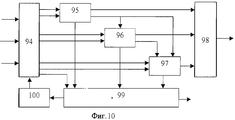
На фиг. 1 представлена функциональная схема устройства для скрининговой диагностики зрения; на фиг.2 - блока формирования офтальмологических тестов; на фиг.3 - блока формирования программ скрининга; на фиг.4 - блока обработки данных скрининга и формирования заключения; на фиг.5 - блока визометрии; на фиг. 6 - блока визоконтрастометрии; на фиг.7 - блока цветометрии; на фиг.8 - блока бинокулометрии; на фиг.9 - блока кампиметрии; на фиг.10 - блока анализа астигматизма; на фиг.11 - блока определения остроты зрения; на фиг.12 - блока определения фории; на фиг.13 - блока определения фузионных резервов; на фиг.14 - блока анализа анизейконии; на фиг.15 - блока выявления астигматизма; на фиг.16 - блока определения типа астигматизма; на фиг.17 - блока определения вида астигматизма; на фиг.18 - датчика временных интервалов. In FIG. 1 shows a functional diagram of a device for screening diagnostics of vision; figure 2 - block forming ophthalmic tests; figure 3 - block formation of screening programs; figure 4 - block data processing screening and forming conclusions; figure 5 - block visometry; in FIG. 6 - block visocontrastometry; Fig.7 - block colorimetry; on Fig - block binocular; figure 9 - block campimetry; figure 10 - block analysis of astigmatism; figure 11 is a block for determining visual acuity; on Fig - block definition of phoria; on Fig - block determining fusional reserves; on Fig - block analysis of aniseikonia; on Fig - block detection of astigmatism; on Fig - block determining the type of astigmatism; on Fig - block determining the type of astigmatism; on Fig - sensor time intervals.
Устройство для скрининговой диагностики зрения (фиг.1) содержит последовательно соединенные первый блок управления 1, блок регистрации пациента 2, блок формирования офтальмологических тестов 3, первый блок ИЛИ 4, видеоадаптер 5 и блок отображения 6, последовательно соединенные блок формирования программ скрининга 7, первый блок памяти 8, первый буферный блок памяти 9 и второй буферный блок памяти 10, блок выбора программы скрининга 11, последовательно соединенные второй блок управления 12, блок обработки данных скрининга и формирования заключения 13 и принтер 14, второй блок памяти 15, блок ввода данных для поиска 16, первый блок ввода команд 17 и второй блок ввода команд 18, выходы которых соединены соответственно с первым и вторым входами первого блока управления 1, второй выход которого соединен с входом блока формирования программ скрининга 7, а третий выход - через блок выбора программы скрининга 11 - с вторым входом первого блока памяти 8, второй выход блока обработки данных скрининга и формирования заключения 13 соединен с вторым входом первого блока ИЛИ 4, второй и третий выходы блока регистрации пациента 2 соединены соответственно с вторыми входами первого буферного блока памяти 9 и второго буферного блока памяти 10, выходом соединенного с вторым входом блока формирования офтальмологических тестов 3, третий вход которого соединен с четвертым выходом первого блока управления 1, а второй выход - с первым входом второго блока управления 12, второй вход и второй выход которого соединены соответственно с выходом и входом второго блока памяти, пятый выход первого блока управления 1 через блок ввода данных для поиска 16 соединен с третьим входом второго блока управления 12, а шестой выход - с вторым входом блока обработки данных скрининга и формирования заключения 13, при этом первый блок управления 1 выполнен в виде блока пользовательского интерфейса, блок отображения 6 выполнен в виде дисплея персонального компьютера, первый и второй блоки памяти 8 и 15 выполнены в виде баз данных соответственно программ скрининга и результатов обследования пациентов, второй блок управления 12 выполнен в виде блока управления базой данных, а первый и второй блоки ввода команд 17 и 18 выполнены соответственно в виде клавиатуры персонального компьютера и манипулятора типа мышь. A device for screening diagnostics of vision (Fig. 1) comprises a first-connected control unit 1, a patient registration unit 2, an ophthalmological test formation unit 3, a first OR unit 4, a video adapter 5 and a display unit 6, connected in series to a screening program generation unit 7, the first a memory unit 8, a first buffer memory unit 9 and a second buffer memory unit 10, a screening program selection unit 11, a second control unit 12 connected in series, a screening and forming data processing unit is enclosed 13 and a printer 14, a second memory unit 15, a data input unit for searching 16, a first command input unit 17 and a second command input unit 18, the outputs of which are connected respectively to the first and second inputs of the first control unit 1, the second output of which is connected to the input the screening program generation unit 7, and the third output, through the screening program selection unit 11, with the second input of the first memory unit 8, the second output of the screening data processing unit and generating the conclusion 13 is connected to the second input of the first OR block 4, the second and third outputs of the block patient registration 2 is connected respectively to the second inputs of the first buffer memory unit 9 and the second buffer memory unit 10, the output connected to the second input of the ophthalmological test forming unit 3, the third input of which is connected to the fourth output of the first control unit 1, and the second output to the first input the second control unit 12, the second input and second output of which are connected respectively with the output and input of the second memory unit, the fifth output of the first control unit 1 through the data input unit for search 16 is connected with the third input of the second control unit 12, and the sixth output with the second input of the screening and processing data processing unit 13, wherein the first control unit 1 is made in the form of a user interface unit, the display unit 6 is made in the form of a personal computer display, the first and second memory blocks 8 and 15 are made in the form of databases of screening programs and patient examination results, respectively, the second control unit 12 is made in the form of a database control unit, and the first and second input blocks of commands 17 and 18 are filled respectively in the form of a keyboard of a personal computer and a mouse-type manipulator.
Блок формирования офтальмологических тестов 3 (фиг.2) содержит блок диспетчера тестов скрининга 19, третий буферный блок памяти 20, блок визометрии 21, блок визоконтрастометрии 22, блок цветометрии 23, блок бинокулометрии 24, блок кампиметрии 25, блок анализа астигматизма 26, второй блок ИЛИ 27 и блок накопления и вывода данных скрининга 28, первый вход блока диспетчера тестов скрининга 19, объединенный с первым входом третьего буферного блока памяти 20, является первым входом блока формирования офтальмологических тестов 3, второй вход третьего буферного блока памяти 20 является его вторым входом, его третьим входом является второй вход блока диспетчера тестов скрининга 19, а его первым и вторым выходами являются соответственно выход второго блока ИЛИ 27 и первый выход блока накопления и вывода данных скрининга 28, выходы блока диспетчера тестов скрининга 19 с первого по шестой соединены соответственно с первыми входами блока визометрии 21, блока визоконтрастометрии 22, блока цветометрии 23, блока бинокулометрии 24, блока кампиметрии 25 и блока анализа астигматизма 26, вторые входы которых соединены с первым выходом третьего буферного блока памяти 20, третьи входы - соответственно с выходами блока диспетчера тестов скрининга 19 с седьмого по двенадцатый, первые выходы - соответственно с шестью входами второго блока ИЛИ 27, вторые выходы - соответственно с первыми шестью входами блока накопления и вывода данных скрининга 28, седьмой вход и второй выход которого соединены соответственно с тринадцатым выходом и третьим входом блока диспетчера тестов скрининга 19, четвертый вход которого соединен с вторым выходом первого буферного блока памяти 20. The ophthalmological test forming unit 3 (Fig. 2) contains a screening
Блок формирования программ скрининга 7 (фиг.3) содержит последовательно соединенные блок выбора состава тестов скрининга 29, блок выбора последовательности тестов 30, блок выбора условий тестирования 31 и блок валидатора 32, вход блока выбора состава тестов скрининга 28 является входом блока формирования программ скрининга 7, а первый выход блока валидатора 32 - его выходом, второй выход блока валидатора 32 соединен с вторым входом блока выбора условий тестирования 31. The screening program generation unit 7 (FIG. 3) contains a screening test
Блок обработки данных скрининга и формирования заключения 13 (фиг.4) содержит последовательно соединенные четвертый буферный блок памяти 33, первый блок сравнения 34, блок логического вывода 35, блок формирования отчета 36 и блок формирования печатного отчета 37, первый счетчик 38, блок памяти эталонных данных тестов 39 и блок памяти правил логического вывода 40, вход четвертого буферного блока памяти 33 и первый выход блока формирования отчета 36 являются соответственно первым входом и первым выходом блока обработки данных скрининга и формирования заключения 13, вторым входом и вторым выходом которого являются соответственно второй вход и выход блока формирования печатного отчета 37, второй выход четвертого буферного блока памяти 33 соединен с вторым входом блока формирования отчета 36, а третий выход - с входом запуска первого счетчика 38, выходы блока памяти эталонных данных тестов 39 и блока памяти правил для логического вывода 40 соединены соответственно с вторыми входами первого блока сравнения 34 и блока логического вывода 35, счетный выход первого счетчика 38 соединен с третьим входом первого блока сравнения 34, а выход переполнения - с третьим входом блока формирования отчета 36, третий выход которого соединен с счетным входом первого счетчика 38. The screening and generating data processing unit 13 (Fig. 4) contains a fourth
Блок визометрии 21 (фиг.5) содержит блок диспетчера тестов визометрии 41, пятый буферный блок памяти 42, блок определения остроты зрения 43, блок определения оптической установки глаза 44, третий блок ИЛИ 45 и блок накопления и вывода данных визометрии 46, первый вход блока диспетчера тестов визометрии 41, объединенный с первым входом пятого буферного блока памяти 42, является первым входом блока визометрии 21, второй вход пятого буферного блока памяти 42 является его вторым входом, его третьим входом является второй вход блока диспетчера тестов визометрии 41, а его первым и вторым выходами являются соответственно выход третьего блока ИЛИ 45 и первый выход блока накопления и вывода результатов визометрии 46, первый и второй выходы блока диспетчера тестов визометрии 41 соединены соответственно с первыми входами блока определения остроты зрения 43 и блока определения оптической установки глаза 44, вторые входы которых соединены с первым выходом пятого буферного блока памяти 42, третьи входы - соответственно с третьим и четвертым выходами блока диспетчера тестов визометрии 41, первые выходы - соответственно с двумя входами третьего блока ИЛИ 45, а вторые выходы - соответственно с входами блока накопления и вывода данных визометрии 46 с первого по четвертый, пятый вход и второй выход которого соединены соответственно с пятым выходом и третьим входом блока диспетчера тестов визометрии 41, четвертый вход которого соединен с вторым выходом пятого буферного блока памяти 42, четвертый вход блока определения оптической установки глаза 44 соединен с вторым выходом блока определения остроты зрения 43. The block of visometry 21 (Fig. 5) contains the block of the manager of tests of
Блок визоконтрастометрии 22 (фиг.6) содержит последовательно соединенные третий блок управления 47, первый блок формирования изояркостного изображения 48, блок яркостной модуляции 49 и первый блок композиции 50, выход которого является первым выходом блока визоконтрастометрии, последовательно соединенные второй блок формирования изояркостного изображения 51 и первый блок смещения изображения 52, датчик пространственных частот 53, второй счетчик 54, последовательно соединенные первый блок интерпретации реакции пациента 55 и первый датчик вертикального смещения 56, а также блок формирования видеограммы 57, первый и второй входы третьего блока управления 47 являются соответственно первым и вторым входами блока визоконтрастометрии 22, а второй, третий и четвертый выходы соединены соответственно с первым входом датчика пространственных частот 53, входом установки второго счетчика 54 и первым входом блока формирования видеограммы 57, первый выход которого является вторым выходом блока визоконтрастометрии, вход второго блока формирования изояркостного изображения 51 соединен с вторым выходом первого блока формирования изояркостного изображения 48, выход первого блока смещения изображения 52 соединен с вторым входом первого блока композиции 50, а второй вход - с первым выходом первого датчика вертикального смещения 56, управляющий вход блока яркостной модуляции 49 соединен с первым выходом датчика пространственных частот 53, второй, третий и четвертый входы блока формирования видеограммы 57 соединены соответственно с вторым выходом первого блока интерпретации реакции пациента 55, вторым выходом датчика пространственных частот 53 и вторым выходом первого датчика вертикального смещения 56, второй вход которого соединен с третьим выходом датчика пространственных частот 53, второй вход которого соединен с выходом второго счетчика 54, выход переполнения которого соединен с третьим входом третьего блока управления 47, вход первого блока интерпретации реакции пациента 55 является третьим входом блока визоконтрастометрии. The visocontrastometry unit 22 (Fig. 6) contains a
Блок цветометрии 23 (фиг.7) содержит последовательно соединенные четвертый блок управления 58, первый блок формирования фрагмента оптотипа 59, первый блок цветовой модуляции 60, второй блок композиции 61 и первый блок поворота изображения 62, выход которого является первым выходом блока цветометрии 23, последовательно соединенные второй блок формирования фрагмента оптотипа 63, входом соединенный с вторым выходом четвертого блока управления 58, и второй блок цветовой модуляции 64, выходом соединенный с вторым входом второго блока композиции 61, датчик цветов пороговой таблицы 65, первым входом соединенный с третьим выходом четвертого блока управления 58, а первым и вторым выходами - с вторыми входами соответственно первого и второго блоков цветовой модуляции 60 и 64, последовательно соединенные второй блок интерпретации реакции пациента 66 и первый датчик случайного угла поворота 67, первым выходом подключенный ко второму входу первого блока поворота изображения 62, последовательно соединенные второй блок сравнения 68 и первый блок принятия решения 69, блок выбора тестовых цветов 70 и блок накопления и вывода данных цветометрии 71, выход которого является вторым выходом блока цветометрии 23, первым и вторым входами которого являются соответственно первый и второй входы четвертого блока управления 58, а третьим входом - вход второго блока интерпретации реакции пациента 66, первый и второй входы второго блока сравнения 68 соединены с вторыми выходами соответственно второго блока интерпретации реакции пациента 66 и первого датчика случайного угла поворота 67, первый и второй входы блока выбора тестовых цветов 70 соединены соответственно с четвертым выходом четвертого блока управления 58 и выходом первого блока принятия решения 69, а первый, второй и третий выходы - соответственно с вторым входом датчика цветов пороговой таблицы 65 и первым и вторым входами блока накопления и вывода данных цветометрии 71, второй выход которого соединен с третьим входом четвертого блока управления 58. The colorimetry block 23 (Fig. 7) contains the
Блок бинокулометрии 24 (фиг.8) содержит блок диспетчера тестов бинокулометрии 72, шестой буферный блок памяти 73, блок определения характера бинокулярного сотрудничества 74, блок определения корреспонденции сетчаток 75, блок определения фории 76, блок определения фузионных резервов 77, блок выявления стереопсиса 78, блок анализа анизейконии 79, четвертый блок ИЛИ 80, блок накопления и вывода данных бинокулометрии 81 и блок предварительного анализа результатов бинокулометрии 82, первый вход блока диспетчера тестов бинокулометрии 72, объединенный с первым входом шестого буферного блока памяти 73, является первым входом блока бинокулометрии 24, второй вход шестого буферного блока памяти 73 является его вторым входом, его третьим входом является второй вход блока диспетчера тестов бинокулометрии 72, а его первым и вторым выходами являются соответственно выход четвертого блока ИЛИ 80 и первый выход блока накопления и вывода данных бинокулометрии 81, выходы блока диспетчера тестов бинокулометрии 72 с первого по шестой соединены соответственно с первыми входами блока определения характера бинокулярного сотрудничества 74, блока определения корреспонденции сетчаток 75, блока определения фории 76, блока определения фузионных резервов 77, блока выявления стереопсиса 78 и блока анализа анизейконии 79, вторые входы которых соединены с первым выходом шестого буферного блока памяти 73, третьи входы - соответственно с выходами блока диспетчера тестов бинокулометрии 72 с седьмого по двенадцатый, первые выходы - соответственно с шестью входами четвертого блока ИЛИ 80, вторые выходы - соответственно с первыми шестью входами блока накопления и вывода данных бинокулометрии 81, седьмой вход и второй выход которого соединены соответственно с тринадцатым выходом блока диспетчера тестов бинокулометрии 72 и входом блока предварительного анализа результатов бинокулометрии 82, выходом соединенного с третьим входом блока диспетчера тестов бинокулометрии 72, четвертый вход которого соединен с вторым выходом шестого буферного блока памяти 73. The binoculometry block 24 (Fig. 8) contains the binoculometry
Блок кампиметрии 25 (фиг.9) содержит последовательно соединенные пятый блок управления 83, первый и второй входы которого являются соответственно первым и вторым входами блока кампиметрии 25, блок формирования стимула 84, второй блок смещения изображения 85 и блок подсвета стимула 86, выход которого является первым выходом блока кампиметрии 25, датчик координат стимулов 87, первым входом соединенный с вторым выходом пятого блока управления 83, а первым выходом - с вторым входом второго блока смещения изображения 85, датчик цветов стимула и фона 88, включенный между вторым выходом блока формирования стимула 84 и вторым входом блока подсвета стимула 86, датчик временных интервалов 89, первым, вторым и третьим входами подключенный соответственно к третьему, четвертому и пятому выходам пятого блока управления 83, блок выбора координат текущего стимула 90, третий блок интерпретации реакции пациента 91, вход которого является третьим входом блока кампиметрии 25, второй блок принятия решения 92 и блок накопления и вывода данных кампиметрии 93, выход которого является вторым выходом блока кампиметрии 25, второй выход датчика координат стимулов 87 соединен с первым входом блок выбора координат текущего стимула 90, первый и второй выходы третьего блока интерпретации реакции пациента 91 соединены соответственно с первым и вторым входами второго блока принятия решения 92, первый и второй выходы которого соединены соответственно с вторым входом блока выбора координат текущего стимула 90 и первым входом блока накопления и вывода данных кампиметрии 93, второй вход которого соединен с третьим выходом датчика координат стимулов 87, первый, второй, третий и четвертый выходы блока выбора координат текущего стимула 90 соединены соответственно с вторым входом датчика координат стимулов 87, четвертым входом датчика временных интервалов 89, вторым входом блока накопления и вывода данных кампиметрии 93 и третьим входом пятого блока управления 83, первый и второй выходы датчика временных интервалов 89 соединены соответственно с третьим и четвертым входами второго блока принятия решения 92, третий вход которого объединен с третьим входом блока подсвета стимула 86. The campimetry unit 25 (Fig. 9) contains a
Блок анализа астигматизма 26 (фиг.10) содержит блок диспетчера тестов для анализа астигматизма 94, блок выявления астигматизма 95, блок определения типа астигматизма 96, блок определения вида астигматизма 97, пятый блок ИЛИ 98, блок накопления и вывода данных исследования астигматизма 99 и блок предварительного анализа исследования астигматизма 100, первым и вторым выходами блока анализа астигматизма 26 являются соответственно выход пятого блока ИЛИ 98 и первый выход блока накопления и вывода данных исследования астигматизма 99, а первым, вторым и третьим входами - соответственно первый, второй и третий входы блока диспетчера тестов для анализа астигматизма 94, первый, второй и третий выходы которого соответственно через блок выявления астигматизма 95, блок определения типа астигматизма 96 и блок определения вида астигматизма 97 подключены к трем входам пятого блока ИЛИ 98, а четвертый, пятый и шестой выходы соединены с вторыми входами соответственно блока выявления астигматизма 95, блока определения типа астигматизма 96 и блока 97 определения вида астигматизма, вторые выходы которых соединены соответственно с первым, вторым и третьим входами блока накопления и вывода данных исследования астигматизма 99, второй выход которого через блок предварительного анализа исследования астигматизма 100 подключен к четвертому входу блока диспетчера тестов для анализа астигматизма 94, а четвертый вход - к пятому выходу этого блока, третий выход блока выявления астигматизма 95 соединен с третьими входами блока определения типа астигматизма 96 и блока определения вида астигматизма 97, а третий выход блока определения типа астигматизма 96 - с четвертым входом блока определения вида астигматизма 97. The astigmatism analysis unit 26 (Fig. 10) contains a test manager unit for analyzing
Блок определения остроты зрения 43 (фиг.11) содержит последовательно соединенные шестой блок управления 101, блок формирования оптотипа 102, первый блок масштабирования изображения 103 и второй блок поворота изображения 104, выход которого является первым выходом блока определения остроты зрения 43, первым и вторым входами которого являются соответственно первый и второй входы шестого блока управления 101, датчик масштабных коэффициентов 105, первым входом соединенный с вторым выходом шестого блока управления 101, а первым выходом - с вторым входом первого блока масштабирования изображения 103, последовательно соединенные четвертый блок интерпретации реакции пациента 106, второй датчик случайного угла поворота 107, первым выходом соединенный с вторым входом второго блока поворота изображения 104, последовательно соединенные третий блок сравнения 108, второй блок принятия решения 109, блок выбора масштабного коэффициента 110 и блок оценки остроты зрения 111, первый выход которого является вторым выходом блока определения остроты зрения 43, а второй выход соединен с третьим входом шестого блока управления 101, второй выход и второй вход блока выбора масштабного коэффициента 110 соединены соответственно с вторым входом и вторым выходом датчика масштабных коэффициентов 105, третий выход которого соединен с вторым входом блока оценки остроты зрения 111, третий вход и второй выход которого соединены соответственно с третьим выходом датчика масштабных коэффициентов 105 и третьим входом шестого блока управления 101, первый и второй входы третьего блока сравнения 108 соединены соответственно с вторым выходом второго датчика случайного угла поворота 107 и вторым выходом четвертого блока интерпретации реакции пациента 106, вход которого является третьим входом блока определения остроты зрения 43. The visual acuity determination unit 43 (Fig. 11) contains a
Блок определения фории 76 (фиг.12) содержит седьмой блок управления 112, первый и второй входы которого являются соответственно первым и вторым входами блока определения фории 76, последовательно соединенные третий блок формирования фрагмента оптотипа 113, третий блок цветовой модуляции 114 и третий блок композиции 115, выход которого является первым выходом блока определения фории 76, последовательно соединенные четвертый блок формирования фрагмента оптотипа 116, четвертый блок цветовой модуляции 117, первый блок горизонтального смещения изображения 118 и первый блок вертикального смещения изображения 119, первым выходом подключенный ко второму входу третьего блока композиции 115, первый датчик цветовых анаглифов 120, первым и вторым выходами соединенный с вторыми входами соответственно третьего и четвертого блоков цветовой модуляции 114 и 117, последовательно соединенные пятый блок интерпретации реакции пациента 121, вход которого является третьим входом блока определения фории 76, и блок оценки расхождения фиксации 122, первый выход которого является вторым выходом блока определения фории 76, первый, второй и третий выходы седьмого блока управления 112 соединены соответственно с входами третьего и четвертого блоков формирования фрагмента оптотипа 113 и 116 и первого датчика цветовых анаглифов 120, второй и третий выходы пятого блока интерпретации реакции пациента 121 соединены с вторыми входами соответственно первого блока горизонтального смещения фрагмента 118 и первого блока вертикального смещения фрагмента 119, вторые выходы которых соединены соответственно с вторым и третьим входами блока оценки расхождения фиксации 122, четвертый вход и второй выход которого соединены соответственно с четвертым выходом и третьим входом седьмого блока управления 112. The phorium determination unit 76 (Fig. 12) contains a
Блок определения фузионных резервов 77 (фиг.13) содержит восьмой блок управления 123, первый и второй входы которого являются соответственно первым и вторым входами блока определения фузионных резервов 77, последовательно соединенные пятый блок формирования фрагмента оптотипа 124, пятый блок цветовой модуляции 125, второй блок горизонтального смещения изображения 126 и четвертый блок композиции 127, выход которого является первым выходом блока определения фузионных резервов 76, последовательно соединенные шестой блок формирования фрагмента оптотипа 128, шестой блок цветовой модуляции 129 и третий блок горизонтального смещения изображения 130, первым выходом подключенный ко второму входу четвертого блока композиции 127, блок формирования фонового изображения 131, выходом подключенный к третьему входу четвертого блока композиции 127, второй датчик цветовых анаглифов 132, первым и вторым выходами соединенный с вторыми входами соответственно пятого и шестого блоков цветовой модуляции 125 и 129, последовательно соединенные шестой блок интерпретации реакции пациента 133, вход которого является третьим входом блока определения фузионных резервов 76, и датчик горизонтального смещения 134, блок оценки резервов конвергенции и дивергенции 135, первый выход которого является вторым выходом блока определения фузионных резервов 77, а также инвертор 136, первый, второй, третий и четвертый выходы восьмого блока управления 123 соединены соответственно с входами пятого и шестого блоков формирования фрагмента оптотипа 124 и 128, блока формирования фонового изображения 131 и второго датчика цветовых анаглифов 132, второй выход шестого блока интерпретации реакции пациента 133 соединен с первым входом блока оценки резервов конвергенции и дивергенции 135, первый выход датчика горизонтального смещения соединен с вторым входом третьего блока горизонтального смещения изображения 130 и через инвертор 136 - с вторым входом второго блока горизонтального смещения изображения 126, второй вход и второй выход - соответственно с вторым входом и вторым выходом блока оценки резервов конвергенции и дивергенции 135, третий выход которого и четвертый вход соединены с третьим входом и пятым выходом восьмого блока управления 123. The fusion reserves determination unit 77 (Fig. 13) contains an
Блок анализа анизейконии 79 (фиг.14) содержит девятый блок управления 137, первый и второй входы которого являются соответственно первым и вторым входами блока анализа анизейконии 79, последовательно соединенные седьмой блок формирования фрагмента оптотипа 138, седьмой блок цветовой модуляции 139 и пятый блок композиции 140, выход которого является первым выходом блока анализа анизейконии 79, последовательно соединенные восьмой блок формирования фрагмента оптотипа 141, восьмой блок цветовой модуляции 142, четвертый блок горизонтального смещения изображения 143, второй блок вертикального смещения изображения 144 и второй блок масштабирования 145, первым выходом подключенный ко второму входу пятого блока композиции 140, третий датчик цветовых анаглифов 146, первым и вторым выходами соединенный с вторыми входами соответственно седьмого и восьмого блоков цветовой модуляции 139 и 142, последовательно соединенные седьмой блок интерпретации реакции пациента 147, вход которого является третьим входом блока анализа анизейконии 79, и блок оценки анизейконии 148, первый выход которого является вторым выходом блока анализа анизейконии 79, первый, второй и третий выходы девятого блока управления 137 соединены соответственно с входами седьмого и восьмого блоков формирования фрагмента оптотипа 138 и 141 и третьего датчика цветовых анаглифов 146, второй, третий и четвертый выходы седьмого блока интерпретации реакции пациента 147 соединены с вторыми входами соответственно четвертого блока горизонтального смещения изображения 143, второго блока вертикального смещения фрагмента 144 и второго блока масштабирования 145, второй выход которого соединен с вторым входом блока оценки анизейконии 148, второй выход которого соединен с третьим входом девятого блока управления 137. The aniseikonia analysis block 79 (Fig. 14) contains the
Блок выявления астигматизма 95 (фиг.15) содержит последовательно соединенные десятый блок управления 149, первый и второй входы которого являются соответственно первым и вторым входами блока выявления астигматизма 95, первый блок формирования астигматической фигуры 150 и шестой блок композиции 151, выход которого является первым выходом блока выявления астигматизма 95, последовательно соединенные блок формирования маркера 152, первый вход которого соединен с вторым выходом десятого блока управления 149, и блок поворота маркера 153, выходом соединенный с вторым входом шестого блока композиции 151, последовательно соединенные восьмой блок интерпретации реакции пациента 154, вход которого является третьим входом блока выявления астигматизма 95, датчик угла поворота маркера 155 и блок формирования выходных данных 156, второй и третий выходы восьмого блока интерпретации реакции пациента 154 соединены соответственно с вторыми входами блока формирования маркера 152 и блока формирования выходных данных 156, второй выход датчика угла поворота маркера 155 соединен с вторым входом блока поворота маркера 153, первый выход блока формирования выходных данных 156 является вторым выходом блока выявления астигматизма 95, а второй выход соединен с третьим входом десятого блока управления 149. The astigmatism detection unit 95 (Fig. 15) contains a
Блок определения типа астигматизма 96 (фиг.16) содержит последовательно соединенные одиннадцатый блок управления 157, первый и второй выходы которого являются соответственно первым и вторым выходами блока определения типа астигматизма 96, второй блок формирования астигматической фигуры 158 и третий блок поворота изображения 159, выход которого является первым выходом блока определения типа астигматизма 96, последовательно соединенные девятый блок интерпретации реакции пациента 160, вход которого является третьим входом блока определения типа астигматизма 96, и третий датчик угла поворота 161, первый выход которого соединен с вторым входом третьего блока поворота изображения 159, а второй вход является четвертым входом блока определения типа астигматизма 96, блок оценки положения сильнопреломляющего меридиана 162, первый и второй входы которого соединены соответственно с вторыми выходами девятого блока интерпретации реакции пациента 160 и третьего датчика угла поворота 161, первый выход является вторым выходом блока определения типа астигматизма 96, а второй выход соединен с третьим входом одиннадцатого блока управления 157. The astigmatism type determination unit 96 (Fig. 16) contains the
Блок определения вида астигматизма 97 (фиг.17) содержит двенадцатый блок управления 163, первый и второй входы которого являются соответственно первым и вторым входами блока определения вида астигматизма 97, третий блок формирования астигматической фигуры 164, блок модификации астигматической фигуры 165 и четвертый блок поворота изображения 166, выход которого является первым выходом блока определения вида астигматизма 97, четвертый датчик угла поворота 168, выходом соединенный с вторым входом четвертого блока поворота изображения 166, десятый блок формирования реакции пациента 167, вход которого является третьим входом блока определения вида астигматизма 97, и блок оценки рефракции в главных меридианах 169, первый выход которого является вторым выходом блока определения вида астигматизма 97, а второй выход соединен с третьим входом двенадцатого блока управления 163, первый, второй, третий и четвертый выходы десятого блока формирования реакции пациента 167 соединены соответственно с вторым и третьимвходами блока модификации астигматической фигуры 165, входом блока оценки рефракции в главных меридианах 169 и первым входом четвертого датчика угла поворота 168, второй вход которого является четвертым входом блока определения вида астигматизма 97. The astigmatism type determination unit 97 (Fig. 17) comprises a
Датчик временных интервалов 89 (фиг.18) содержит таймер 170, второй счетчик 171, датчик случайных чисел 172, первый, второй и третий блоки И 173, 174 и 175, первый и второй сумматоры 176 и 177 и RS-триггер 178, вход установки датчика случайных чисел и первые входы первого и второго сумматоров 176 и 177 являются соответственно первым, вторым и третьим входами датчика временных интервалов 89, четвертым входом которого являются объединенные вход запуска датчика случайных чисел 172, вход переустановки таймера 170 и вход сброса второго счетчика 171, выход таймера 170 соединен с счетным входом второго счетчика 171, выход которого соединен с объединенными первыми входами первого, второго и третьего блоков И 173, 174 и 175, вторые входы которых соединены соответственно с выходом датчика случайных чисел 172, выходом первого сумматора 176 и выходом второго сумматора 177, вторые входы первого и второго сумматоров 176 и 177 соединены с выходом датчика случайных чисел 172, S-вход и R-вход RS-триггера соединены соответственно с выходами первого и второго блоков И 173 и 174, а выход является первым выходом датчика временных интервалов 89, вторым выходом которого является выход третьего блока И 175. The time interval sensor 89 (Fig. 18) contains a timer 170, a second counter 171, a random number sensor 172, a first, second and third blocks And 173, 174 and 175, a first and second adders 176 and 177 and an RS-trigger 178, the installation input the random number sensor and the first inputs of the first and second adders 176 and 177 are respectively the first, second and third inputs of the time interval sensor 89, the fourth input of which is the combined input of the random number sensor start 172, reset timer input 170 and reset input of the second counter 171, output timer 170 connection with the counting input of the second counter 171, the output of which is connected to the combined first inputs of the first, second and third blocks And 173, 174 and 175, the second inputs of which are connected respectively to the output of the random number sensor 172, the output of the first adder 176 and the output of the second adder 177, the second the inputs of the first and second adders 176 and 177 are connected to the output of the random number sensor 172, the S-input and R-input of the RS trigger are connected respectively to the outputs of the first and second blocks And 173 and 174, and the output is the first output of the time interval sensor 89, sec whose output is the output of the third block And 175.
Устройство (фиг.1) работает следующим образом. The device (figure 1) works as follows.
Первый блок управления 1 обеспечивает интерактивное взаимодействие устройства с пациентом и/или медперсоналом, которое осуществляется с помощью ввода команд через блоки ввода команд 17 и 18. Аппаратные прерывания от мыши или клавиатуры с выходов указанных устройств поступают в блок управления 1 в виде соответствующих сообщений для текущего окна, имеющего фокус ввода. Сообщение в виде команды поступает, когда пользователь выбирает пункт меню, или щелкает мышью по соответствующему органу управления графического интерфейса - кнопки инструментальной панели, органу управления диалогового окна и т. д. , или нажимает определенные клавиши клавиатуры. Щелчок мышью по значку инструментальной панели "Выполнить" запускает текущую программу скрининга. The first control unit 1 provides interactive interaction of the device with the patient and / or medical staff, which is carried out by entering commands through the input blocks of commands 17 and 18. Hardware interrupts from the mouse or keyboard from the outputs of these devices are received in the control unit 1 in the form of corresponding messages for the current a window having input focus. A message in the form of a command arrives when the user selects a menu item, or clicks on the corresponding control element of the graphical interface - the toolbar button, the dialog box control element, etc., or presses certain keyboard keys. Clicking on the Run toolbar icon launches the current screening program.
Команда запуска поступает с первого выхода первого блока управлений 1 в блок регистрации пациента 2, в который вводятся учетные данные пациента (фамилии, имени, отчества, даты рождения), а также добавляется текущая системная дата проведения скрининга. Эти данные передаются во второй буферный блок памяти 10. Одновременно с другого выхода блока регистрации пациента 2 в первый буферный блок памяти 9 поступает команда, по которой данные текущей программы скрининга переписываются во второй буферный блок памяти 10 с определенным смещением относительно начального адреса данных, определяемым фиксированной длиной участка памяти, отводимого для учетных данных пациента. The start command comes from the first output of the first control unit 1 to the patient registration unit 2, into which the patient's credentials (last name, first name, middle name, date of birth) are entered, and the current system date of the screening is added. These data are transmitted to the second buffer memory unit 10. At the same time, from the other output of the patient registration unit 2, the first buffer memory unit 9 receives a command by which the data of the current screening program are copied to the second buffer memory unit 10 with a certain offset relative to the initial data address, determined by a fixed the length of the memory allocated for the patient’s credentials.
Эти данные поступают на второй вход блока формирования офтальмологических тестов 3 (фиг.2), на первый вход которого с блока регистрации пациента 2 поступает стартовый сигнал начала скрининга. Процесс тестирования включает предъявление испытуемому определенных тестовых изображений (стимулов, оптотипов) и получение от него информации в процессе диалога. Диалог предполагает вывод на экране (в статусном окне в нижней части экрана) определенных указаний для испытуемого: какие команды системе он должен подать при наличии тех или иных зрительных ощущений, например, путем нажатия клавиши "Ввод" ("Да") или "Пробел" ("Нет"). Помимо клавишей "Ввод" и "Пробел" используются клавиши-стрелки управления курсором, когда требуется выбрать один из четырех вариантов: слева, справа, внизу, вверху. Все клавиши расположены по периферии клавиатуры и легко находятся "вслепую". These data are fed to the second input of the ophthalmological test formation unit 3 (Fig. 2), the first input of which from the patient registration unit 2 receives the start signal for the start of screening. The testing process includes presenting the test subject with certain test images (stimuli, optotypes) and receiving information from him in the process of dialogue. The dialogue involves the conclusion on the screen (in the status window at the bottom of the screen) of certain indications for the subject: what commands should he give to the system in the presence of certain visual sensations, for example, by pressing the Enter key (Yes) or the Spacebar ("Not"). In addition to the "Enter" and "Space" keys, arrow keys are also used when you need to choose one of four options: left, right, bottom, top. All keys are located on the periphery of the keyboard and are easily "blind."
Команды пользователя в виде скан-кодов нажатых клавишей поступают с первого блока управления 1 на третий вход блока формирования офтальмологических тестов 3, где осуществляется интерпретация поданных команд, на основе которой делается вывод о наличии адекватной или неадекватной реакции пациента в ответ на предъявленные стимулы. User commands in the form of scan codes pressed by a key are sent from the first control unit 1 to the third input of the ophthalmological test formation unit 3, where the instructions given are interpreted, based on which it is concluded that there is an adequate or inadequate patient response in response to the presented stimuli.
По завершении тестирования по заданной программе, данные тестирования с второго входа блока формирования офтальмологических тестов 3 поступают на первый вход второго блока управления 12. Данные пациента ищутся во втором блоке памяти (базе данных) 15. Если данные пациента найдены в базе данных, карточные данные скрининга записываются в электронную карточку пациента, в противном случае заводится новая карточка, которой автоматически присваивается уникальный регистрационный индекс, и полученные данные записываются в эту карточку. Upon completion of testing according to a given program, the test data from the second input of the ophthalmological test unit 3 is fed to the first input of the second control unit 12. The patient data is searched in the second memory unit (database) 15. If the patient data is found in the database, card screening data they are recorded in the patient’s electronic card, otherwise a new card is created, which is automatically assigned a unique registration index, and the received data is recorded in this card.
Данные скрининга поступают на первый вход блока 13 обработки данных скрининга и формирования заключения, который формирует отчеты для отображения на экране и для печати. Первый отчет через первый блок ИЛИ 4 выводится на экран, а второй - на принтер 14 (автоматически или по команде с первого блока управления 1, поступающей на второй вход блока 13, в зависимости от выбранного для данной программы скрининга режима). The screening data is supplied to the first input of the screening and processing data processing unit 13, which generates reports for display on the screen and for printing. The first report, through the first OR block 4, is displayed on the screen, and the second report is sent to the printer 14 (automatically or by command from the first control unit 1, which is sent to the second input of block 13, depending on the mode selected for the screening program).
Впоследствии данные скрининга могут быть получены путем подачи соответствующей команды с пятого выхода первого блока управления 1 через блок ввода данных для поиска 16 на третий вход второго блока управления 12. Если данные для поиска введены правильно и соответствующая запись обнаружена во втором блоке памяти 15, данные будут тем же способом выведены на экран или на принтер. Subsequently, the screening data can be obtained by sending the appropriate command from the fifth output of the first control unit 1 through the data input unit for search 16 to the third input of the second control unit 12. If the data for the search is entered correctly and the corresponding record is found in the second memory unit 15, the data will be displayed in the same way on the screen or on the printer.
Формирование программы скрининга осуществляется в блоке формирования программ скрининга 7 (фиг.3), команда на который поступает с второго выхода первого блока управления 1. Блок формирования программ скрининга 7 представляет собой блок модального диалога, например многостраничного диалога класса Property Sheet, включающего отдельные страницы-диалоги. В диалоговом блоке выбора состава тестов скрининга 29 осуществляется выбор состава тестов скрининга из предлагаемого набора. В блоке выбора последовательности тестов 30 можно менять временную последовательность тестов. В блоке выбора условий тестирования 31 задаются конкретные параметры тестов: монокулярно и/или бинокулярно, для левого или правого глаза, с оптической коррекцией и/или без нее и т. д. Блок валидатора 32 проверяет корректность задания, при некорректных данных пользователь возвращается в блок выбора условий тестирования 31. По завершении диалога данные записываются в первый блок памяти (базу данных программ скрининга) 8. The formation of the screening program is carried out in the block for the formation of screening programs 7 (Fig. 3), the command for which comes from the second output of the first control unit 1. The block for the formation of screening programs 7 is a block of modal dialogue, for example, a multi-page dialog of the Property Sheet class, which includes separate pages - dialogues. In the dialog box for selecting the composition of the screening tests 29, a selection of the composition of the screening tests from the proposed set is performed. In the block sequence selection tests 30 you can change the time sequence of tests. In the block for selecting
По команде с третьего выхода первого блока управления 1 в блоке выбора программы скрининга 11 осуществляется выбор конкретной программы в зависимости от диагностической задачи, например, путем селекции имени нужной программы в блоке управления типа "Комбинированный список" инструментальной панели. Данные выбранной программы из первого блока памяти 8 записываются в первый буферный блок памяти 9, в котором и остаются до тех пор, пока пользователь не выберет другую программу. К данным выбранной программы скрининга во втором буферном блоке памяти 9 добавляются данные текущего режима графического вывода, получаемые от видеоадаптера: размер экрана, разрешение экрана, цветовое разрешение, гамма. Эти данные необходимы для масштабирования изображения в реальных физических координатах, и соответствия цветовой палитры. Каждый раз при инициализации тестирования данные из первого буферного блока памяти 9 будут поступать во второй буферный блок памяти 10, как описано выше. A command from the third output of the first control unit 1 in the screening program selection block 11 selects a specific program depending on the diagnostic task, for example, by selecting the name of the desired program in the "Combined list" control unit of the toolbar. The data of the selected program from the first memory block 8 is recorded in the first buffer memory block 9, in which it remains until the user selects another program. To the data of the selected screening program in the second buffer block of memory 9, data of the current graphic output mode received from the video adapter are added: screen size, screen resolution, color resolution, gamma. This data is necessary to scale the image in real physical coordinates, and match the color palette. Each time the test is initialized, data from the first buffer memory block 9 will flow into the second buffer memory block 10, as described above.
Блок формирования офтальмологических тестов 3 работает следующим образом. Block forming ophthalmic tests 3 works as follows.
По стартовому сигналу, поступающему на первый вход блока диспетчера тестов скрининга 19, данные из второго буферного блока памяти 10 записываются в третий буферный блок памяти 20, откуда часть данных, относящаяся к организации процесса скрининга поступает в блок диспетчера тестов скрининга 19. Данные эти представляют собой список тестов (в выбранном порядке их следования) с соответствующими флагами. Если для конкретного теста выставлен флаг (установлен бит) выполнения, тест выполняется, если флаг сброшен - тест не выполняется. Следующая группа флагов определяет исследуемый глаз: правый (oculi dextri), левый (oculi sinistri), оба (oculi utriusqui). Если, например, выставлен флаг OCULI_DEXTRI, то правый глаз проверяется, в противном случае - нет. Если выставлен флаг тестирования с оптической коррекцией - тестирование проводится с оптической коррекцией. Флаги выставляются в блоке выбора условий тестирования 31 и комбинируются с помощью логической операции ИЛИ. According to the start signal received at the first input of the screening
Блок диспетчера тестов скрининга 19 осуществляет сканирование списка тестов с проверкой флагов. Если соответствующий флаг выставлен, на соответствующем выходе блока появляется стартовый сигнал, поступающий на первый вход одного из блоков: визометрии 21, визоконтрастометрии 22, цветометрии 23, бинокулометрии 24, кампиметрии 25 и анализа астигматизма 26. В этом случае блок диспетчера тестов скрининга 19 работает как дешифратор: в зависимости от кодовой комбинации на входе появляется сигнал на одном из выходов. По стартовому сигналу на первом входе одного из перечисленных блоков, он начинает процесс тестирования, при этом данные для тестирования с первого выхода третьего буферного блока памяти 20 считываются данные для тестирования, поступающие на вторые входы всех указанных блоков. Данные для каждого конкретного теста записаны с фиксированным смещением относительно общего начального адреса данных, поэтому каждый блок считывает только свои данные по заранее известному фиксированному смещению и длине данных (а также общие для всех тестов данные видеоадаптера.). The screening
В отношении команд пользователя, поступающих на третий вход блока формирования офтальмологических тестов 3 (второй вход блока диспетчера тестов скрининга 19), блок диспетчера тестов скрининга 19 действует как коммутатор, подключая его к соответствующему выходу, соединенному с третьим входом активного тестирующего блока 21-26. In relation to user commands received at the third input of the ophthalmological test forming unit 3 (second input of the screening test dispatcher block 19), the screening
Для отображения тестов на дисплее используется метафора логического ИЛИ - сигналы с выхода текущего активного тестирующего блока с его первого выхода поступают через второй блок ИЛИ на первый выход блока формирования офтальмологических тестов 3 для отображения на дисплее. To display the tests on the display, a logical OR metaphor is used - the signals from the output of the current active testing unit from its first output are sent through the second OR block to the first output of the ophthalmological test formation unit 3 for display.
По завершении конкретного теста данные тестирования с второго выхода соответствующего блока (21-26) поступают в блок накопления и вывода данных скрининга 28. В этом блоке выставляется флаг соответствующего теста и флаги условий, при которых проводилось тестирование (с оптической коррекцией или без нее, левый, правый глаз, оба глаза), а также записываются данные результатов теста. Адрес смещения начала записи определяется номером входа блока накопления и вывода данных скрининга 28, на который поступают данные. Upon completion of a specific test, the test data from the second output of the corresponding block (21-26) is sent to the accumulation and output unit of
Три блока: визоконтрастометрии 22, цветометрии 23 и кампиметрии 25 выполняют по одному тесту. Блоки: визометрии 21, бинокулометрии 24 и анализа астигматизма 26 выполняют группу тестов, связанных с исследованием соответствующей функции зрения. Каждый из трех последних блоков работает, аналогично блоку формирования офтальмологических тестов 3, организуя внутри "большого цикла" скрининга "маленькие циклы" тестирования конкретных функций зрения. Three blocks:
По завершении записи подается сигнал на третий вход блока диспетчера тестов скрининга 19, который возобновляет сканирование для перехода к следующему тесту (или повтору текущего, например, с другими условиями оптической коррекции). Когда будет просканирован весь список, с выхода блока диспетчера тестов скрининга 19 на вход блока накопления и вывода данных скрининга 28 поступает сигнал, по которому блок выдает данные скрининга на второй выход блока формирования офтальмологических тестов 3 и процесс тестирования завершается. Upon completion of recording, a signal is sent to the third input of the screening
Блок обработки данных скрининга и формирования заключения 13 (фиг.4) работает следующим образом. Данные скрининга записываются в четвертый буферный блок памяти 33. С помощью первого счетчика 38 организуется цикл их последовательного считывания в первый блок сравнения 34, на второй вход которого поступают данные из блока памяти эталонных данных тестов 39. Эталонные данные представляют собой значения норм и допусков, и могут быть получены из общетеоретических соображений или путем набора статистики при тестировании заведомо здоровых людей. Данные по результатам сравнения поступают в блок логического вывода 35, на второй вход которого поступают данные из блока памяти правил логического вывода 40. Указанный блок можно рассматривать как базу знаний, в том понимании этого термина, которое принято в исследованиях по искусственному интеллекту. Применительно, например, к языку логического программирования Prolog блок памяти правил логического вывода 40 представляет собой базу данных фактов и набор предикатов и на основе логического анализа имеющихся данных обеспечивает их "рациональное" размещение на одном или нескольких листах при выводе на печать. The processing unit of the screening data and the formation of the conclusion 13 (figure 4) works as follows. The screening data is written to the fourth
После считывания и анализа всех данных из четвертого буферного блока памяти 33 сигнал переполнения первого счетчика 38 поступает на третий вход блока формирования отчета 36. По этому сигналу блок выводит отчет через первый выход на отображение (первый выход блока обработки данных скрининга и формирования заключения 13), а печатный отчет передает в блок формирования печатного отчета 37. Этот блок перерисовывает печатный отчет в контексте отображения принтера и выводит на принтер автоматически или по команде на его втором входе. After reading and analyzing all the data from the fourth
Блок визометрии 21 (фиг. 5) организует "малый цикл" тестирования (определение остроты зрения и оптической установки глаза) и работает аналогично блоку формирования офтальмологических тестов 3. Отличие состоит в том, что данные тестирования из блока определения остроты зрения 43 поступают в блок определения оптической установки глаза 44, который использует их при проведении соответствующего теста. The visometry unit 21 (Fig. 5) organizes a "small cycle" of testing (determination of visual acuity and optical installation of the eye) and works similarly to the ophthalmological test generation unit 3. The difference is that the test data from the visual
Изменения пространственной контрастной чувствительности (ПКЧ) при многих патологических состояниях могут быть первым признаком заболевания зрительной системы. Однако, поскольку очень сходные нарушения могут возникать при самой разнообразной патологии как зрительно-нервного, так и оптического аппарата, данные визоконтрастометрии расцениваются как скрининговые, с последующим уточнением причин снижения ПКЧ другими методами. Changes in spatial contrast sensitivity (PPC) in many pathological conditions may be the first sign of a disease in the visual system. However, since very similar disorders can occur with a wide variety of pathologies of both the opto-nervous and optical apparatus, the data of visocontrastometry are regarded as screening, with subsequent clarification of the reasons for the decrease in RPC by other methods.
Поскольку рецептивные поля зрительного анализатора подобны системе локальных фильтров разных пространственных частот и ориентации, лучшими тестовыми стимулами для их возбуждения служат разноконтрастные ахроматические или хроматические синусоидальные решетки. Since the receptive fields of the visual analyzer are similar to a system of local filters of different spatial frequencies and orientations, the best test stimuli for their excitation are different-contrast achromatic or chromatic sinusoidal gratings.
Тестовая контрастная решетка представляет собой изображение, яркость которого меняется по синусоидальному закону в горизонтальной плоскости с плавным изменением индекса модуляции (обычно по логарифмическому закону) в вертикальной плоскости. Контрастность горизонтальной строки решетки равна соответствующему индексу модуляции. The test contrast grating is an image whose brightness changes according to the sinusoidal law in the horizontal plane with a smooth change in the modulation index (usually according to the logarithmic law) in the vertical plane. The contrast of the horizontal row of the grating is equal to the corresponding modulation index.
Испытуемый легко различает контрастные вертикальные полосы внизу решетки и слабо различает их вверху, где контрастность минимальна. Если решетка закрыта снизу изояркостным фоновым изображением и остается только узкая полоса сверху, то для испытуемого эта полоса будет сливаться с фоновым изображением. Если постепенно расширять полосу, то испытуемый начиная с некоторого момента начнет различать вертикальные полосы. Ширина полосы в этот момент однозначно характеризует пороговую контрастную чувствительность на данной пространственной частоте решетки. The subject easily distinguishes between contrasting vertical stripes at the bottom of the grille and faintly distinguishes them at the top, where the contrast is minimal. If the lattice is closed from below by an iso-brightness background image and only a narrow strip remains from above, then for the subject this strip will merge with the background image. If the strip is gradually expanded, then the subject, starting at some point, will begin to distinguish between vertical stripes. The bandwidth at this moment uniquely characterizes the threshold contrast sensitivity at a given spatial frequency of the grating.
Реализуется эта методика тестирования в блоке визоконтрастометрии 22 (фиг. 6). Процесс тестирования начинается с поступлением стартового сигнала на первый вход третьего блока управления 47. По этому сигналу с второго входа этого блока считываются необходимые данные для проведения теста. Данные эти формируются в блоке выбора условий тестирования 31 и поступают с первого выхода третьего буферного блока памяти 20. This testing technique is implemented in the block of visocontrastometry 22 (Fig. 6). The testing process begins with the start signal arriving at the first input of the
Эти данные включают:
- условия оптической коррекции (с оптической коррекцией и/или без нее) и тестируемый глаз (OD и/или OS); тестирование проводится монокулярно;
- расстояние до экрана, исследуемый диапазон пространственных частот и количество исследуемых в этом диапазоне точек;
- цвета контрастных решеток при визоконтрастометрии (ахроматическая или/и хроматическая: красная, зеленая, синяя).This data includes:
- conditions for optical correction (with and without optical correction) and the test eye (OD and / or OS); testing is monocular;
- distance to the screen, the investigated range of spatial frequencies and the number of points studied in this range of points;
- the colors of contrasting gratings for visocontrastometry (achromatic and / or chromatic: red, green, blue).
По завершении считывания третий блок управления 47 формирует набор эквидистантных точек в соответствии с заданными дальностью и диапазоном и количеством исследуемых пространственных частот. Upon completion of reading, the
Кортеж { Fi / D} в виде массива данных с второго выхода блока переписывается в датчик пространственных частот 52, и по сигналу с третьего выхода блока производится установка второго счетчика 54. После этого по сигналу с первого выхода третьего блока управления 47 первый блок формирования изояркостного изображения 48 формирует ахроматическое или хроматическое изображение постоянной яркости Uо = 120 единиц. Это изображение модулируется по яркости. Одновременно изояркостное изображение с второго входа первого блока формирования изояркостного изображения 48 переписывается во второй блок формирования изояркостного изображения 51, с выхода которого поступает на первый блок смещения изображения 52. Немодулированное изображение с выхода этого блока в первом блоке композиции 50 накладывается на модулированное по яркости изображение, полностью или частично его закрывая. С помощью клавиши управления курсором "стрелка вниз" можно смещать немодулированное изображение вниз, приоткрывая верхнюю часть контрастной решетки, а с помощью клавиши "стрелка вверх" - закрывать ее. Скан-коды от указанных нажатых клавишей поступают на вход первого блока интерпретации реакции пациента 55. В соответствии с поступившим скан-кодом на первом выходе этого блока формируется соответственно положительное или отрицательное значение кванта смещения, поступающее на первый вход первого датчика вертикального смещения 56, который представляет собой интегратор, преобразующий сигнал приращения на входе в сигнал положения на выходе. Этот сигнал поступает через первый выход на второй вход первого блока смещения изображения 52, смещая немодулированное изображение в вертикальном направлении.A tuple {Fi / D} in the form of an array of data from the second output of the block is copied to the
Началу различения контрастных полос соответствует нажатие клавиши "Ввод". Соответствующий скан-код на входе первого блока интерпретации реакции пациента 55 формирует сигнал на его втором выходе, который поступает в блок формирования видеограммы 57. По этому сигналу блок формирования видеограммы 57 считывает текущее значение из датчика пространственных частот 53 и текущее значение смещения, характеризующее пространственную контрастную чувствительность, из первого датчика вертикального смещения 56. Эта пара значений {Fi/D, yi} записывается в соответствующий массив данных в порядке возрастания пространственной частоты Fi. The beginning of distinguishing contrasting bands corresponds to pressing the Enter key. The corresponding scan code at the input of the first patient
По окончании формирования текущей пары точек для видеограммы блок формирования видеограммы 57 выдает сигнал на счетный вход второго счетчика, который представляет собой счетчик событий. Счетчик инкриминируется и выдает на второй вход датчика пространственных частот 53 указатель на следующее значение Fi+1 / D. Датчик пространственных частот 53 устанавливает на своих выходах новые значения и выдает на третьем выходе сигнал, сбрасывающий первый датчик вертикального смещения 56. Процесс повторяется. Когда весь список исследуемых пространственных частот будет исчерпан, сигнал переполнения второго счетчика подается в третий блок управления 47. Процесс тестирования прекращается. По сигналу с четвертого выхода третьего блока управления блок формирования видеограммы 57 преобразует записанный массив пар чисел в видеограмму - табличную зависимость ПКЧ (1/m) от пространственной частоты F, и выдает ее на второй выход блока визоконтрастометрии 22 в виде кортежа {(1/ mi,Fi)}, i {0,..., N-1}. Upon completion of the formation of the current pair of points for the videogram, the
В основу диагностики цветовосприятия положена методика пороговых таблиц (Рабкина, Юстовой - Волкова или другие), заключающаяся в априорном подборе пар цветов, не различаемых при той или иной патологии цветового зрения. Например, таблицы Юстовой-Волкова, включают двенадцать пар цветов; по 4 для испытаний красного и зеленого цветоприемников, 3 - для синего и 1 - контрольная, служащая для исключения симуляции. Таким образом, предусмотрена трехступенчатая оценка цветослабости каждого приемника, а для красного и зеленого - тест на цветослепоту. Испытания проводятся с помощью блока цветометрии 23 (фиг. 7). Испытуемому предъявляется симметричный по форме, но асимметричный по окраске оптотип. Например, четыре расположенных крестом квадрата, три из которых окрашены в один цвет контрольной пары, а четвертый - в другой. Оптотип повернут случайным образом, и испытуемому предлагается указать направление, в котором имеется цветовое отличие. The basis for the diagnosis of color perception is the methodology of threshold tables (Rabkin, Yustova-Volkova or others), which consists in a priori selection of pairs of colors that are not distinguishable with one or another pathology of color vision. For example, Yustova-Volkov tables include twelve pairs of flowers; 4 for testing red and green color detectors, 3 for blue and 1 - control, used to exclude simulation. Thus, a three-step evaluation of the color weakness of each receiver is provided, and a test for color blindness is provided for red and green. Tests are carried out using the colorimetry block 23 (Fig. 7). The subject is presented with a symmetry in shape, but asymmetric in color, of the optotype. For example, four squares arranged in a cross, three of which are painted in one color of the control pair, and the fourth in another. The optotype is rotated randomly, and the subject is asked to indicate the direction in which there is a color difference.
Блок цветометрии 23 работает следующим образом. На первый и второй входы четвертого блока управления поступают стартовый сигнал и данные для тестирования в виде 12 пар значений RGB контрольных цветов. Эти значения устанавливаются в блоке выбора условий тестирования 31 при формировании программы скрининга. Эти 12 пар через третий выход четвертого блока управления 58 поступают в датчик цветов пороговой таблицы 65. Четвертый блок управления 58 формирует матрицу переходов. The
Эта матрица переходов с четвертого выхода четвертого блока управления 58 записывается в блок выбора тестовых цветов 70, на первом выходе которого устанавливается 0 - нулевое смещение адреса первой пары. Этот номер поступает в датчик цветов пороговой таблицы 65, на первом и втором выходах которого устанавливаются соответствующие значения RGB. This transition matrix from the fourth output of the
С первого и второго выходов четвертого блока управления 58 инициализируются первый и второй блоки формирования фрагментов оптотипа 59 и 63 (например, три квадрата и один квадрат). Эти фрагменты в первом и втором блоках цветовой модуляции принимают окраску в соответствии с значениями RGB на первом и втором уходах датчика цветов пороговой таблицы 65. Затем оба фрагмента объединяются на втором блоке композиции 61 и поворачиваются на случайный, кратный 90 градусам угол в первом блоке поворота изображения 62. В результате цветовая асимметрия оптотипа воспринимает одно из 4 значений: слева, справа, внизу или вверху. Этот оптотип через первый выход блока цветометрии 23 поступает на отображение. From the first and second outputs of the
Для выбора одного из четырех указанных вариантов необходимо нажать одну из 4 клавишей управления курсором: "стрелка влево" "стрелка вправо", "стрелка вверх" или "стрелка вниз". В соответствии с скан-кодом, поступающим на его вход, второй блок интерпретации реакции пациента 66 формирует значение угла, кратного 90 градусам, которое поступает с его второго выхода во второй блок сравнения 68. На первом выходе второго блока интерпретации реакции пациента 66 формируется сигнал, по которому первый датчик случайного угла поворота 67 через второй выход сбрасывает текущее значение угла во второй блок сравнения 68 и устанавливает на своем первом выходе новое случайное значение, которое поступает в первый блок поворота изображения 62. Второй блок сравнения сравнивает два значения угла и выдает на своем выходе логический сигнал 0 или 1, который поступает в первый блок принятия решения 69. Блок этот принимает решение по критерию "m из n", и может быть реализован, например, на основе двух счетчиков. Первый счетчик событий считает все сигналы на входе, второй - только сигналы логической единицы. При переполнении второго счетчика на выходе устанавливается сигнал логической единицы, в противном случае при переполнении первого счетчика на выходе устанавливается сигнал логического нуля. По любому из сигналов переполнения оба счетчика сбрасываются. To select one of the four options indicated, you must press one of the 4 cursor keys: left arrow, right arrow, up arrow or down arrow. In accordance with the scan code received at its input, the second patient
Сигнал с выхода первого блока принятия решения 69 поступает в блок выбора тестовых цветов 70. На основе логического значения входного сигнала и таблицы переходов формируется сигнал перехода к следующему испытанию с другой парой цветов или сигнал завершения теста. Сигнал перехода к следующему испытанию вызывает передачу через первый выход в датчик цветов пороговой таблицы 65 номера соответствующей контрольной пары цветов. Кроме того, если входной сигнал блока выбора тестовых цветов 70 имел значение логической единицы (положительный результат с данной парой цветов) на второй выход блока поступает номер соответствующего испытания i {0,...,11}. В блоке накопления и вывода данных цветометрии 71 в 12-битовой выходной величине выставляется соответствующий бит. The signal from the output of the
Если же адрес перехода указывает на код завершения теста, то в блок накопления и вывода данных цветометрии 71 по второму входу поступает сигнал завершения теста и вывода накопленных результатов. На третий вход четвертого блока управления 58 поступает сигнал завершения теста, а блок накопления и вывода данных цветометрии 71 выводит данные тестирования в виде двоичного слова длиной 12 бит. На основе анализа выставленных флагов в блоке обработки данных скрининга и формирования заключения 13 будет сформулирован соответствующий диагноз или сообщение о неадекватной реакции пациента, если в выходных данных блока цветометрии не выставлено ни одного бита. If the transition address indicates the test completion code, then the signal for completing the test and displaying the accumulated results is received at the second input to the accumulation and output unit of
Бинокулометрия включает проверку характера бинокулярного сотрудничества, проверку корреспонденции сетчаток, оценку мышечного баланса - фории, оценку фузионных резервов, оценку стереопсиса и анизейконии. Наблюдение проводится с разделением полей, когда одна часть изображения наблюдается левым глазом, а другая - правым. Достигается это тем, что различные части изображения имеют строго дополнительные цвета - цветовые анаглифы (например, красный и синий или красный и зеленый) и наблюдаются сквозь очки с соответствующими разделительными светофильтрами. Binoculometry includes checking the nature of binocular collaboration, checking retinal correspondence, assessing muscle balance - phoria, assessing fusion reserves, evaluating stereopsis and aniseukonia. Observation is performed with field separation when one part of the image is observed with the left eye and the other with the right eye. This is achieved by the fact that the various parts of the image have strictly complementary colors - color anaglyphs (for example, red and blue or red and green) and are observed through glasses with corresponding dividing filters.
Работа блока бинокулометрии 24 (фиг.8) аналогична работе блока формирования офтальмологических тестов 3. Особенность его заключается в наличии блока предварительного анализа результатов бинокулометрии 82. Этот блок по завершении каждого теста бинокулометрии анализирует его результаты на предмет определения целесообразности проведения оставшихся тестов и соответствующим образом корректирует флаги выполнения в блоке диспетчера тестов бинокулометрии 72. The operation of binoculometry block 24 (Fig. 8) is similar to the operation of the ophthalmological test formation block 3. Its peculiarity lies in the presence of a preliminary analysis unit for
Функциональная схема блока кампиметрии 25 (фиг.9) использует метафору "подсвета" стимулов. Блок работает следующим образом. На первый и второй входы пятого блока управления поступают стартовый сигнал и данные для тестирования. Эти данные устанавливаются в блоке выбора условий тестирования 31 и включают: - расстояние до экрана; - характер распределения исследуемых точек в видимом пространстве; RGB тест-объекта его размеры; - RGB фона; временные интервалы - время экспозиции тест-объекта, время релаксации (математическое ожидание) и время, отводимое на реакцию пациента. The functional block diagram of the campimetry block 25 (Fig. 9) uses the metaphor of "highlighting" the stimuli. The block works as follows. The first and second inputs of the fifth control unit receive a start signal and data for testing. These data are set in the block for selecting
Распределение исследуемых точек может иметь как изотропный характер в пределах исследуемого видимого пространства (матрица в прямоугольных или полярных координатах с варьируемым шагом) или могут исследоваться определенные участки этого поля (зона Бьеррума или шесть фиксированных точек для выявления ранних глаукоматозных изменений). Размер стимула задается в процентах относительно стандартного в периметрии диаметра 0.43 град., эквивалентного объекту с размером III по Гольдману. Возможность изменения размера стимула может быть использована, например, для исследования поля зрения при низком зрении. По сигналу на первом выходе пятого блока управления блок формирования стимула 84 формирует изображения стимула и фона с значениями RGB фона. Данные RGB стимула и фона передаются в датчик цветов стимула и фона 88. The distribution of the studied points can be either isotropic within the studied visible space (matrix in rectangular or polar coordinates with a variable step) or certain sections of this field can be studied (Bierrum zone or six fixed points to detect early glaucomatous changes). The size of the stimulus is set as a percentage relative to the standard perimeter diameter of 0.43 degrees, equivalent to an object with a size of III according to Goldman. The ability to change the size of the stimulus can be used, for example, to study the field of view with low vision. According to the signal at the first output of the fifth control unit, the
По сигналу с второго выхода пятого блока управления в датчике координат стимулов 87 формируется кортеж координат исследуемых точек поля зрения. According to the signal from the second output of the fifth control unit, a tuple of coordinates of the studied points of the field of view is formed in the stimulus coordinate
Блок выбора координат текущего стимула 90 организует цикл вывода стимулов в случайном порядке, датчик временных интервалов 89 вместе с блоком подсвета стимула 86 - заданные временные интервалы экспозиции, реакции и релаксации. Информация о количестве исследуемых точек пересылается из датчика координат стимулов 87 в блок выбора координат текущего стимула 90 для установки счетчика (предела счета). Начальная установка счетчика равна -1, и соответствующий указатель на -1-ый элемент кортежа передается в датчик координат стимулов 87. The coordinate selection block of the
Изначально -1-ый стимул выводится в произвольной точке экрана с цветом фона и поэтому невидим. Initially, the 1st stimulus is displayed at an arbitrary point on the screen with the background color and is therefore invisible.
Для начала процесса тестирования необходима подача команды путем нажатия определенной клавиши (например, "Пробел"). Скан-код нажатой клавиши поступает на вход третьего блока интерпретации реакции пациента 91, с первого выхода которого поступает сигнал на первый вход второго блока принятия решения 92. Блок выдает соответствующий сигнал на второй вход блока выбора координат текущего стимула 90. Датчик инкриминируется и указывает нулевой вектор случайной последовательности координат. В соответствии с этим указателем датчик случайных координат стимулов 87 передает эти координаты на второй блок смещения изображения 85, который смещает стимул в заданное место экрана. To start the testing process, you need to submit a command by pressing a specific key (for example, "Space"). The scan code of the pressed key goes to the input of the third unit for interpreting the response of the
С второго выхода блока выбора координат текущего стимула 90 в датчик временных интервалов 89 поступает сигнал, синхронизирующий вывод стимула. По этому сигналу блок формирует импульс подсвета, определяемый длительностью стимула и задержанный относительно входного сигнала на случайное время релаксации. На первые три входа датчика временных интервалов 89 поступает информация о длительности релаксации, длительности экспозиции стимула и "времени реакции". From the second output of the coordinate selection block of the
Импульс подсвета поступает на третий вход блока подсвета стимула 86, куда также поступает информация о цвете стимула и цвете фона из датчика цветов стимула и фона 88. Блок подсвета стимула 86 "подсвечивает" стимул на время длительности сигнала экспозиции на третьем входе блока. "Подсвет" заключается в установке цвета стимула передним фронтом сигнала на третьем входе и его переустановке в цвет фона задним фронтом того же сигнала. The backlight pulse is fed to the third input of the
Одновременно передний фронт "импульса подсвета" запускает временной селектор во втором блоке принятия решения 92. Он предназначен для стробирования сигналов на втором входе этого блока. На второй вход этого блока поступают сигналы при нажатии испытуемым клавиши "Ввод". Т.е. реакция испытуемого селектируется по времени - она должна поступать не раньше начала экспозиции стимула. Если сигнал фиксации стимула не поступит в течение времени, отводимого на реакцию пациента, то сигналом, датчиком временных интервалом 88 на его втором выходе (задержанном относительно начала "импульса подсвета" на "время реакции"), поступающим на четвертый вход второго блока принятия решения 92, временной селектор закрывается. Задним фронтом селектирующего импульса формируется сигнал начала следующего цикла экспозиции стимула, который передается в блок выбора координат текущего стимула 90 и процесс повторяется. At the same time, the leading edge of the “illumination pulse” starts the time selector in the
Если сигнал на втором входе второго блока принятия решения 92 появляется раньше сигнала на его четвертом входе, то на его втором выходе формируется сигнал, поступающий на первый вход блока накопления и вывода данных кампиметрии 93. По этому сигналу блок считывает текущие координаты стимула из датчика координат стимулов 87. Эти данные накапливаются в блоке. Поступившим на второй вход второго блока принятия решения 92 сигналом временной селектор закрывается, передается сигнал в блок выбора координат текущего стимула 90 и процесс повторяется. При этом сигнал с второго выхода блока выбора координат текущего стимула 90 переустанавливает датчик временных интервалов 89, так что сигнал на его втором выходе не появляется. If the signal at the second input of the
По переполнении счетчика цикла в блоке выбора координат текущего стимула 90 на его третьем выходе появляется сигнал, поступающий в блок накопления и вывода данных кампиметрии 93, на четвертом выходе - сигнал, оповещающий пятый блок управления 83 о завершении теста. Upon overflow of the cycle counter in the coordinate selection block of the
Датчик временных интервалов может быть реализован с помощью трех программируемых таймеров или с помощью одного таймера, как показано на фиг.18. Датчик временных интервалов 89 работает следующим образом. The time slot sensor can be implemented using three programmable timers or using one timer, as shown in FIG. The
Сигнал с четвертого входа блока переустанавливает (сбрасывает и устанавливает вновь) таймер 170 и сбрасывает второй счетчик 171. Одновременно запускается датчик случайных чисел 172, генерирующий на выходе случайное число с математическим ожиданием, установленным на его установочном входе (время релаксации). Второй счетчик 171 считает сигналы таймера и результаты счета выдает на входы трех блоков И 173, 174 и 175. Первый блок И 173 формирует на выходе сигнал при совпадении значения на выходе второго счетчика 171 с значением на выходе датчика случайных чисел 172, т.е. этот сигнал задержан относительно сигнала на четвертом входе датчика временных интервалов 89 на случайное время релаксации. Этим сигналом устанавливается RS-триггер. The signal from the fourth input of the block resets (resets and sets again) the
Второй блок И 174 формирует на выходе сигнал при совпадении значения на выходе второго счетчика 171 с значением на выходе датчика случайных чисел 172 плюс значение на первом входе первого сумматора 176 (время экспозиции). Этим сигналом сбрасывается RS-триггер, на выходе которого (на первом выходе датчика временных интервалов 89) формируется импульс подсвета стимула с длительностью, равной заданному времени экспозиции. Сигнал на выходе третьего блока И 175 задержан относительно начала экспозиции стимула на "время реакции пациента", которое поступает на первый вход второго сумматора 177. Если следующий сигнал на четвертый вход датчика временных интервалов 89 придет раньше, то второй счетчик будет сброшен раньше, чем успеет отсчитать необходимое значение, и сигнал на выходе третьего блока И 175 так и не будет сформирован. The second block And 174 generates an output signal when the value at the output of the
Методы исследования астигматизма основаны на неравномерном видении астигматическим глазом линий различной ориентации в астигматических фигурах. Работа блока исследования астигматизма 26 аналогична работе блока формирования офтальмологических тестов 3, блока визометрии 21 и блока бинокулометрии 24. The methods for studying astigmatism are based on uneven vision by the astigmatic eye of lines of different orientations in astigmatic figures. The operation of the
Для работы блока определения типа астигматизма 96 (фиг.10) и блока определения вида астигматизма 97 требуется информация о положении более сильно преломляющего меридиана. Предварительная информация получается в блоке выявления астигматизма 95 и передается в указанные блоки. Если эта информация отсутствует, соответствующие блоки используют нулевое значение по умолчанию. Выходные данные блока анализа астигматизма 26 содержат флаг наличия или отсутствия астигматизма, а также данные о виде и типе астигматизма и данные положения более сильно преломляющего меридиана по перевернутой шкале ТАВО. For the operation of the unit for determining the type of astigmatism 96 (Fig. 10) and the unit for determining the type of
Острота зрения является одним из основных критериев оценки способности к зрительному анализу форм, размеров, структуры и ориентации объектов в пространстве, поэтому определение остроты зрения относится к числу обязательных методик функциональных исследований органа зрения. Visual acuity is one of the main criteria for assessing the ability to visual analysis of the shapes, sizes, structure and orientation of objects in space, so the determination of visual acuity is one of the mandatory methods of functional research of the organ of vision.
В блоке определения остроты зрения 43 (фиг.11) реализована методика исследования остроты зрения по minimum separable. По определению острота зрения равна отношению максимального расстояния, с которого испытуемый различает детали оптотипа, к расстоянию, с которого их различает человек с нормальным зрением. Поскольку для нормального зрения различительная способность составляет одну угловую минуту, острота зрения количественно равна величине, обратной угловому размеру минимально различимых деталей, выраженному в угловых минутах. In the block for determining visual acuity 43 (Fig. 11), a technique for studying visual acuity by minimum separable is implemented. By definition, visual acuity is equal to the ratio of the maximum distance from which the subject distinguishes the details of the optotype to the distance from which they are distinguished by a person with normal vision. Since for normal vision, the distinguishing ability is one angular minute, visual acuity is quantitatively equal to the reciprocal of the angular size of the minimum distinguishable parts, expressed in angular minutes.
Для определения остроты зрения в офтальмологической практике используются различные оптотипы: кольца Ландольта, "трезубцах" Снеллена или Пфлюгера и т.д. Различаемая деталь (например, прорезь в кольце) составляет 20% от размера оптотипа. To determine visual acuity in ophthalmic practice, various optotypes are used: Landolt rings, Snellen or Pfluger "tridents", etc. A distinguishable part (for example, a slot in the ring) is 20% of the size of the optotype.
Используемая методика предполагает предъявление испытуемому оптотипов разных размеров с фиксацией остороты зрения по минимальному распознанному оптотипу. The technique used involves presenting the subject with optotypes of different sizes with fixation of visual acuity according to the minimum recognized optotype.
Блок определения остроты зрения 43 работает следующим образом. На первый вход шестого блока управления 101 поступает стартовый сигнал, а на второй вход - данные для проведения тестирования. Данные эти включают: расстояние; - RGB оптотипа и фона; вид используемого оптотипа (кольца Ландольта, оптотипы Снеллена и Пфлюгера, штриховой оптотип Волкова); шкалу размеров. The unit for determining
По сигналу на первом выходе шестого блока управления 101 блок формирования оптотипа 102 формирует заданный вид оптотипа с заданным значением RGB и размером, соответствующим для заданного расстояния остроте зрения 1,0. Одновременно по сигналу с второго выхода шестого блока управления 101 в датчике масштабных коэффициентов 105 формируется заданная шкала относительных размеров, длина шкалы (количество масштабных коэффициентов) передается в блок выбора масштабного коэффициента 110, где устанавливается счетчик. Начальное значение счетчика равно 0. Это значение указывает на смещение текущего масштабного коэффициента относительно начала шкалы. Оптотип масштабируется в первом блоке масштабирования изображения 103, поворачивается на случайный угол, кратный 90 градусам, во втором блоке поворота изображения 104 и через первый выход блока выводится на экран. According to the signal at the first output of the
Четыре клавиши-стрелки управления курсором указывают ориентацию оптотипа. В соответствии с скан-кодом нажатой клавиши четвертый блок интерпретации реакции пациента 106 на своем втором выходе формирует значение угла, кратное 90 градусам. Это значение передается в третий блок сравнения 108. Любое из четырех значений скан-кода вызывает подачу сигнала во второй датчик случайного угла поворота 107. По этому сигналу датчик сбрасывает текущее значение угла поворота во второй блок сравнения 108 и устанавливает на первом выходе (втором входе второго блока поворота изображения 104) новое значение угла поворота. Four arrow keys to control the orientation of the optotype. In accordance with the scan code of the pressed key, the fourth unit for interpreting the reaction of the
Второй блок сравнения 108 и второй блок принятия решения 109 работают так же, как и соответствующие блоки в блоке цветометрии. Реализуется принятие решения по критерию "m из n ". Сигнал логического нуля с выхода второго блока принятия решения 109 инкриминирует счетчик в блоке выбора масштабного коэффициента 110, который сдвигает указатель на его втором выходе на следующий масштабный коэффициент в датчике масштабных коэффициентов 105. Процесс повторяется для другого размера оптотипа. Сигнал логической единицы на входе блока выбора масштабного коэффициента 110 вызывает сигнал логической единицы на его первом выходе. По этому сигналу блок оценки остроты зрения 111 считывает текущее значение масштабного коэффициента из датчика масштабных коэффициентов 105, формирует по этому значению оценку остроты зрения и выдает ее на первый выход, одновременно с второго выхода оповещая шестой блок управления 101 о завершении теста. По сигналу переполнения счетчика блок выбора масштабного коэффициента 110 выдает на первом входе сигнал логического нуля. При этом в выходных данных выставляется флаг незавершенности теста, означающий, что исследуемая острота зрения ниже нижнего предела. Этот предел определяется размером экрана и составляет 0.03 - 0.05. The
Определение оптической установки глаза осуществляется с помощью блока определения оптической установки глаза 44, выполненного реализующим дуохромный тест. Диагностика с помощью дуохромного теста основана на физическом явлении хроматической аберрации в оптической системе глаза. Поскольку зеленые лучи преломляются в оптической системе глаза сильнее, чем красные, то для гиперметропического глаза фокусировка будет лучше на зеленом фоне, а для миопического - на красном. Следовательно, и оптотипы представляются более контрастными на том или ином фоне. The determination of the optical installation of the eye is carried out using the unit for determining the optical installation of the
Блок определения характера бинокулярного сотрудничества 74 выполнен реализующим четырехточечный цветовой тест Уорса. Реализация теста заключается в выводе статической картинки на экран и организации диалога через статусное окно. Тест заключается в наблюдении испытуемым через очки-светофильтры четырех светящихся окон разного цвета, расположенных в виде повернутой на бок буквы "Т". Диалог с обследуемым ведется через статусное окно. Организация диалога осуществляется с помощью матрицы переходов, аналогичной матрице, которая используется в цветометрии. Тестирование по Уорсу не разделяет нормального бинокулярного зрения с ведущим глазом и асимметричного бинокулярного зрения с аномальной корреспонденцией сетчаток - привлекается дополнительная информация о наличии или отсутствии явного косоглазия. Поскольку устройство такой информацией не располагает, в этом случае привлекается дополнительный тест на определение корреспонденции сетчаток. При истинности предиката "монокулярное зрение" процесс тестирования прекращается, при истинности предиката "одновременное зрение" исследуется только фория (выявление гетеротропии). The unit for determining the nature of
Блок определения корреспонденции сетчаток 75 выполнен реализующим тестирование последовательных образов по Чермаку - Бильшовскому. Перед испытуемым последовательно включаются горизонтальная и вертикальная вспышки. Одна наблюдается левым, другая - правым глазом. Реализуется это путем управляемого таймером кратковременного вывода на экран вертикальной и горизонтальной линий, окрашенных в цвета цветовых анаглифов. Если расхождения перекрестия не наблюдается, корреспонденция сетчаток нормальная, в противном случае - аномальная. Этим двум альтернативам соответствует, например, нажатие клавишей "Ввод" или "Пробел". По результатам теста выставляется соответствующий флаг. The retina correspondence
Если тест задан при составлении программы скрининга, то он проводится только в случае, если при тестировании по Уорсу установлена истинность предиката "возможно асимметричное бинокулярное зрение с аномальной корреспонденцией сетчаток". If the test was specified during the preparation of the screening program, then it is carried out only if, when testing according to Wors, the predicate “the asymmetric binocular vision with abnormal correspondence of the retina” is established.
Блок определения фории 76 (фиг.12) определяет характер мышечного баланса и величину расхождения фиксации. На первый и второй входы седьмого блока управления 112 поступает стартовый сигнал и данные для тестирования - дальность D и RGB цветовых анаглифов, устанавливаемые в блоке выбора условий тестирования 32. Можно выбрать, например, красный и синий или красный и зеленый цвета, в зависимости от того, какими цветофильтрами располагает пользователь. The unit for determining phoria 76 (Fig. 12) determines the nature of muscle balance and the magnitude of the divergence of fixation. The first and second inputs of the
По сигналам с первого и второго выходов седьмого блока управления 112 в третьем и четвертом блоках формирования фрагмента оптотипа 113 и 116 формируются два фрагмента симметричного оптотипа, например три стороны симметричного креста и его четвертая сторона или окружность и крест в центре. Эти фрагменты приобретают цвета цветовых анаглифов в третьем и четвертом блоках цветовой модуляции 114 и 117 и объединяются в целое изображение в третьем блоке композиции 115. Based on the signals from the first and second outputs of the
RGB цветовых анаглифов с третьего выхода седьмого блока управления поступают в первый датчик цветовых анаглифов 120, а оттуда на входы третьего и четвертого блоков цветовой модуляции 114 и 116. RGB color anaglyphs from the third output of the seventh control unit enter the first
Один из фрагментов по пути к третьему блоку композиции проходит через первые блоки соответственно горизонтального или вертикального смещения изображения 118 и 119, управляемые соответственно с второго и третьего выходов пятого блока интерпретации реакции пациента 121. Сигналы на этих выходах формируются в ответ на нажатие клавишей управления курсором ("стрелки влево - вправо" и "вверх - вниз" соответственно). О восстановлении симметрии видимого изображения устройство оповещается нажатием клавиши "Ввод". На первом выходе пятого блока интерпретации реакции пациента 121 формируется сигнал, поступающий в блок оценки расхождения фиксации 122. Этот блок считывает данные смещения из первых блоков горизонтального и вертикального смещения изображения 118 и 119 и дальность из седьмого блока управления. Вектор смещения (х, у) преобразуется в вектор расхождения фиксации (х / D, у / D), который подается на выход блока определения фории 76, а на третий вход седьмого блока управления 112 передается сигнал завершения теста. One of the fragments on the way to the third block of the composition passes through the first blocks of horizontal or vertical displacement of
Методика оценки фузионных резервов, реализованная в блоке определения фузионных резервов 77 (фиг.13), заключается в следующем. Испытуемому предъявляется фоновое изображение, видимое бинокулярно, и две монокулярно наблюдаемые идентичные детали. Сначала эти детали совмещены в пространстве, затем начинают расходиться по горизонтали. При малом расхождении изображения двух глаз все равно сливаются в одно, и испытуемый вместо двух деталей видит одну. Когда зрительная линия перемещается за пределы фузионных резервов, детали начинают восприниматься раздельно. В этот момент фиксируется их расхождение, определяющее величину фузионных резервов. The methodology for assessing fusional reserves, implemented in the block for determining fusional reserves 77 (Fig.13), is as follows. The subject is presented with a background image that is visible binocularly, and two monocularly observed identical details. First, these details are combined in space, then they begin to diverge horizontally. With a small discrepancy, the images of the two eyes still merge into one, and the subject sees one instead of two details. When the visual line moves beyond the fusional reserves, the details begin to be perceived separately. At this moment, their discrepancy is fixed, which determines the value of fusional reserves.
Работа блока определения фузионных резервов 77 во многом сходна с работой блока определения фории. The operation of the fusion
На первый и второй входы восьмого блока управления 123 также поступают стартовый сигнал и данные для проведения теста. Однако формируется три изображения: фоновое - в блоке формирования фонового изображения 131 и два фрагмента - в пятом и шестом блоках формирования фрагмента оптотипа 124 и 128. Фрагменты приобретают окраску цветовых анаглифов в пятом и шестом блоках цветовой модуляции 125 и 129. The first and second inputs of the
Три изображения объединяются в четвертом блоке композиции 127. Два фрагмента перед тем, как попасть в этот блок, проходят через соответствующие блоки горизонтального смещения изображения 126 и 130. Оба этих блока управляются с выхода датчика горизонтального смещения 134, но один напрямую, а другой через - инвертор. В результате оба фрагмента синхронно перемещаются по горизонтали в противоположных направлениях. Датчик горизонтального смещения 134 управляется с первого выхода шестого блока интерпретации реакции пациента 133, на вход которого поступают скан-коды клавишей управления курсором "стрелки влево - вправо". Three images are combined in the fourth block of
Фрагменты оптотипа представляют собой две вертикальные риски, перемещающиеся вдоль горизонтальной белой полосы, являющейся частью фонового изображения. По периферии экрана фоновое изображение может содержать что угодно - буквы, например. Горизонтальная бинокулярно наблюдаемая линия служит для нейтрализации гетерофории, если последняя имеет место. Fragments of an optotype are two vertical risks moving along a horizontal white strip that is part of the background image. On the periphery of the screen, the background image can contain anything - letters, for example. The horizontal binocularly observed line serves to neutralize heterophory, if the latter takes place.
Момент видимого расхождения рисок соответствует нажатию клавиши "Ввод". Этот сигнал поступает в блок оценки резервов конвергенции и дивергенции 135. По этому сигналу блок считывает горизонтальное смещение Х из датчика горизонтального смещения 134 и дальность D из восьмого блока управления 123. Формируется угловая величина 2X/D, определяющая искомые фузионные резервы. The moment of visible discrepancy between the marks corresponds to pressing the Enter key. This signal is fed to the convergence and divergence
Дальнейшее поведение блока оценки резервов конвергенции и дивергенции 135 зависит от состояния флага завершения теста в этом блоке. Изначально этот флаг сброшен. Тогда блок оценки резервов конвергенции и дивергенции 135 на втором выходе выдает сигнал сброса датчика горизонтального смещения 134, на третьем выходе - сигнал повторения теста и устанавливает флаг завершения. The further behavior of the convergence and divergence
По сигналу повторения теста на третьем выходе блока оценки резервов конвергенции и дивергенции 135 восьмой блок управления 123 организует повтор теста. Если в первом испытании линия визирования перемещалась к носу клавишей "стрелка влево", то теперь она перемещается к виску клавишей "стрелка вправо". В остальном процесс аналогичен. According to the test repetition signal, at the third output of the convergence and divergence
По завершении второго испытания и формирования оценки фузионных резервов дивергенции в блоке оценки резервов конвергенции и дивергенции 135 снова проверяется флаг завершения теста. Теперь он установлен и с третьего выхода блока в восьмой блок управления 123 выдается сигнал завершения теста, а с первого выхода блока - результаты. Upon completion of the second test and the formation of an estimate of the fusional reserves of divergence in the block for evaluating the reserves of convergence and
Блок выявления стереопсиса 78 строится аналогично блоку 77. За счет горизонтальной диспаратности риски и фоновое изображение при наличии стереопсиса воспринимаются как расположенные на разной глубине, а при его отсутствии - как расположенные в одной плоскости. The
Перемещение рисок в горизонтальной плоскости осуществляется для нейтрализации механизма фузии. Риски разводятся до тех пор, пока не начинают наблюдаться раздельно. Сама величина расхождения в данном тесте никакой информации не несет и поэтому не фиксируется (соответствующая этой цели связь между блоками отсутствует). Отсутствует и горизонтальная линия. Направление перемещения линии фиксации при разведении рисок может быть любым, поэтому отпадает необходимость во второй итерации. В зависимости от того, воспринимаются детали расположенными на разной глубине или в одной плоскости, нажимаются "Ввод" или "Пробел". В зависимости от скан-кода нажатой клавиши выставляется флаг наличия или отсутствия стереопсиса. Moving the scribe in the horizontal plane is carried out to neutralize the fusion mechanism. Risks are divorced until they begin to be observed separately. The discrepancy value in this test does not carry any information and therefore is not fixed (there is no communication between the blocks corresponding to this goal). There is also no horizontal line. The direction of movement of the fixation line when breeding the scribes can be any, so there is no need for a second iteration. Depending on whether the details are perceived located at different depths or in the same plane, press "Enter" or "Space". Depending on the scan code of the pressed key, the flag of the presence or absence of a stereoopsis is set.
Методика тестирования анизейконии заключается в предъявлении испытуемому симметричного изображения, левая и правая половины которого наблюдаются раздельно. При наличии анизейконии изображение будет восприниматься как асимметричное - обе половины видимого изображения будут иметь различный размер. The method of testing aniseikonia consists in presenting the subject with a symmetrical image, the left and right halves of which are observed separately. In the presence of aniseikonia, the image will be perceived as asymmetric - both halves of the visible image will have a different size.
Блок анализа анизейконии 79 (фиг.14) работает следующим образом. Формируются два фрагмента, например, в виде направленных навстречу друг другу скобок соответственно в седьмом и восьмом блоках формирования фрагмента оптотипа 138 и 141. Изображения принимают окраску цветовых анаглифов в седьмом и восьмом блоках цветовой модуляции 139 и 142 и объединяются в пятом блоке композиции 140. Ввиду невозможности фузионного слияния столь различных объектов, они воспринимаются раздельно. The analysis unit of aniseikonia 79 (Fig) works as follows. Two fragments are formed, for example, in the form of brackets directed towards each other, respectively, in the seventh and eighth blocks of formation of a fragment of
Второй фрагмент может перемещаться по горизонтали и вертикали и изменять свой размер с помощью соответственно четвертого блока горизонтального смещения изображения 143, второго блока вертикального смещения изображения 144 и второго блока масштабирования 145. Задачей испытуемого является "состыковать" видимые изображения фрагментов и уравнять их в размерах. Сигналы смещения формируются с помощью седьмого блока интерпретации реакции пациента 147, четвертого блока горизонтального смещения изображения 143 и второго блока вертикального смещения изображения 144. The second fragment can be moved horizontally and vertically and resized using the fourth horizontal displacement block of the
Уравниваются в размерах фрагменты путем масштабирования второго фрагмента во втором блоке масштабирования 145, сигнал управления на который поступает с четвертого выхода седьмого блока интерпретации реакции пациента 147. Этот сигнал возникает при нажатии клавишей "+" или "-" - положительное или отрицательное приращение размера, а второй блок масштабирования 145 интегрирует эти приращения. Факт уравнивания видимых размеров соответствует нажатию клавиши "Ввод". Fragments are equalized in size by scaling the second fragment in the
На первом выходе седьмого блока интерпретации реакции пациента 147 формируется сигнал, поступающий в блок оценки анизейконии 148. По этому сигналу блок считывает значение коэффициента масштабирования из второго блока масштабирования 145. Если неподвижное изображение имеет цвет светофильтра перед правым глазом, то масштабный коэфиициент и является искомой оценкой анизейконии. В блоке выбора условий тестирования цветовые анаглифы необходимо установить так, чтобы второй цветовой анаглиф соответствовал фильтру перед левым глазом. Затем блок оценки анизейконии 148 информирует сигналом на своем втором выходе девятый блок управления 137 о завершении теста и выводит полученные данные. At the first output of the seventh patient
Блок выявления астигматизма 95 (фиг.15) работает следующим образом. По сигналу на первом выходе десятого блока управления 149 первый блок формирования астигматической фигуры 150 формирует изображение лучистой фигуры Пуркинье. Организуется диалог для выявления ощущений пациента. Общий принцип организации диалога с помощью матрицы переходов такой же, как и при тестировании по Уорсу. The astigmatism detection unit 95 (Fig. 15) works as follows. According to the signal at the first output of the
Если испытуемый видит все лучи фигуры одинаково четкими или слегка размытыми, то астигматизм либо отсутствует, либо он равномерно-смешанный, т.е. аметропия в главных сечениях одинакова по величине и противоположна по знаку. Проверка истинности предикатов осуществляется в восьмом блоке интерпретации реакции пациента 154. Если истинны предикаты "сильная аметропия" или "отсутствие астигматизма", то в блок формирования выходных данных 156 поступает сигнал завершения теста. Этот блок выдает на выходе биты-флаги и информирует десятый блок управления 149 о завершении теста. Если истинны предикаты "астигматизм" или "равномерно-смешанный астигматизм", то в блок формирования маркера 152 из восьмого блока интерпретации реакции пациента 154 поступает сигнал, по которому формируется маркер. Скан-коды клавишей управления курсором формируют на первом выходе восьмого блока интерпретации реакции пациента 154 сигнал изменения угла поворота маркера, поступающий на первый вход датчика угла поворота маркера 155. Этот блок преобразует поступающий сигнал в сигнал угла положения маркера, который поступает на второй вход блока поворота маркера 153. If the subject sees all the rays of the figure equally clear or slightly blurry, then astigmatism is either absent or evenly mixed, i.e. ametropia in the main sections is the same in magnitude and opposite in sign. Verification of the validity of predicates is carried out in the eighth block of interpretation of the patient’s
Задачей испытуемого является выставление маркера в направлении наиболее четко видимого меридиана. Этой ситуации соответствует нажатие клавиши "Ввод". В блок формирования выходных данных 156 поступает сигнал, по которому он считывает данные положения маркера из датчика угла поворота маркера 155 и завершает тест. Если астигматизм не обнаружен, то на этом процесс тестирования прекращается. The subject's task is to place a marker in the direction of the most clearly visible meridian. Pressing the Enter key corresponds to this situation. The output
Если же выявлен астигматизм, то с помощью блока определения типа астигматизма 96 (фиг.16) можно уточнить положение главных меридианов и определить тип астигматизма. Уточнение положения осей производится с помощью так называемой стрелы Раубичека, представляющей собой черную двускатную симметричную гиперболу с ортогональными асимптотами. Фигура может поворачиваться вокруг оси. Эта методика и реализуется в блоке определения типа астигматизма 96. Формируется изображение "стрелы" Раубичека с помощью второго блока формирования астигматической фигуры 158, а поворачивается в третьем блоке поворота изображения 159 точно так же, как поворачивается маркер в блоке выявления астигматизма 95. Третий датчик угла поворота 161 имеет вход начальной установки (второй вход), на который поступает значение угла главного меридиана, полученное в предыдущем тесте. Если сигнал на этом входе отсутствует (тест на выявления астигматизма не проводился), то устанавливается по умолчанию нулевое начальное значение. If astigmatism is detected, then using the unit for determining the type of astigmatism 96 (Fig. 16), you can clarify the position of the main meridians and determine the type of astigmatism. The position of the axes is refined using the so-called Raubichek arrow, which is a black gable symmetric hyperbola with orthogonal asymptotes. The figure can rotate around an axis. This technique is implemented in the block for determining the type of
Положению "стрелы" в направлении главного меридиана соответствует нажатие клавиши "Ввод". По сигналу с девятого блока интерпретации реакции пациента 160 блок оценки положения сильнопреломляющего меридиана 162 считывает значение угла из третьего датчика угла поворота 161, выдает его на выход и сигналом в одиннадцатый блок управления 157 завершает тест. The position of the "arrow" in the direction of the main meridian corresponds to pressing the Enter key. Based on a signal from the ninth patient
Тестирование для определения вида астигматизма осуществляется в блоке определения вида астигматизма 97 (фиг.17). Изображение фигуры Парпарова формируется в третьем блоке формирования астигматической фигуры 164 и модифицируется в блоке модификации астигматической фигуры 165, на который поступают сигналы из десятого блока формирования реакции пациента 167. Ось фигуры разворачивается в направлении ранее найденного угла положения сильнопреломляющего меридиана. Это значение поступает на второй вход четвертого датчика угла поворота 168. Трем альтернативам: "зеленый фон", "красный фон", "безразлично" - соответствует нажатие трех клавишей, скажем, "стрелка влево", "стрелка вправо", "пробел". После выбора одной из трех альтернатив, результаты передаются в блок оценки рефракции в главных меридианах 169, инкриминируется счетчик цикла в десятом блоке формирования реакции пациента 167, из которого на первый вход четвертого датчика угла поворота 168 поступает сигнал поворота изображения на 90 градусов. Процесс повторяется для более слабо преломляющего меридиана. После повторного выбора одной из трех альтернатив по сигналу переполнения счетчика данные передаются в блок оценки рефракции в главных меридианах 169. Теперь в передаваемых данных выставлен флаг завершения теста, который передается в двенадцатый блок управления 163 и тест завершается. Testing to determine the type of astigmatism is carried out in the block determining the type of astigmatism 97 (Fig.17). The image of the Parparov figure is formed in the third block for forming the astigmatic figure 164 and is modified in the block for modifying the astigmatic figure 165, to which signals from the tenth block for forming the reaction of the
Устройство позволяет проводить скриннинговую диагностику основных функций зрения в том числе при массовых профилактических офтальмологических обследованиях детского и взрослого контингента в дошкольных и школьных учебных заведениях, на предприятиях, в Вооруженных Силах РФ, для обеспечения контроля за состоянием зрительного анализатора в поликлиниках, стационарах и других медицинских учреждениях, а также для проведения исследований при оценке эффективности лечебных и реабилитационных офтальмологических мероприятий. Устройство также может использоваться для самотестирования. Преимущества устройства заключаются в автоматизации деятельности оптометриста, что значительно повышает производительность, при одновременном снижении требований к уровню квалификации обслуживающего персонала и стоимости диагностического оборудования. Автоматическое сохранение данных скрининга в электронной форме позволяет при необходимости легко организовать их статистическую обработку, а также наблюдать динамику при проведении исследований по оценке эффективности лечебных и реабилитационных офтальмологических мероприятий. The device allows for screening diagnostics of the main functions of vision, including during mass preventive ophthalmological examinations of children and adults in preschool and school educational institutions, at enterprises, in the Armed Forces of the Russian Federation, to ensure monitoring of the state of the visual analyzer in clinics, hospitals and other medical institutions , as well as for conducting research in assessing the effectiveness of medical and rehabilitation ophthalmological measures. The device can also be used for self-testing. The device’s advantages are the automation of the optometrist’s activities, which significantly increases productivity, while reducing the requirements for the level of qualification of staff and the cost of diagnostic equipment. Automatic saving of screening data in electronic form makes it possible, if necessary, to easily organize their statistical processing, as well as observe the dynamics when conducting studies to evaluate the effectiveness of medical and rehabilitation ophthalmological measures.
Источники информации:
1. Розенблюм Ю.З. "Оптометрия". - Санкт-Петербург, "Гиппократ", 1996.Sources of information:
1. Rosenblum Yu.Z. "Optometry". - St. Petersburg, "Hippocrates", 1996.
Claims (20)
Priority Applications (1)
| Application Number | Priority Date | Filing Date | Title |
|---|---|---|---|
| RU2001134563/14A RU2210972C1 (en) | 2001-12-21 | 2001-12-21 | Device for carrying out screening vision function diagnosis |
Applications Claiming Priority (1)
| Application Number | Priority Date | Filing Date | Title |
|---|---|---|---|
| RU2001134563/14A RU2210972C1 (en) | 2001-12-21 | 2001-12-21 | Device for carrying out screening vision function diagnosis |
Publications (2)
| Publication Number | Publication Date |
|---|---|
| RU2210972C1 true RU2210972C1 (en) | 2003-08-27 |
| RU2001134563A RU2001134563A (en) | 2004-03-20 |
Family
ID=29246157
Family Applications (1)
| Application Number | Title | Priority Date | Filing Date |
|---|---|---|---|
| RU2001134563/14A RU2210972C1 (en) | 2001-12-21 | 2001-12-21 | Device for carrying out screening vision function diagnosis |
Country Status (1)
| Country | Link |
|---|---|
| RU (1) | RU2210972C1 (en) |
Cited By (9)
| Publication number | Priority date | Publication date | Assignee | Title |
|---|---|---|---|---|
| RU2454207C2 (en) * | 2006-06-30 | 2012-06-27 | Алькон, Инк. | System and method for modification of surgical operations with application of graphic interface with drag transfer |
| RU2454166C2 (en) * | 2010-06-30 | 2012-06-27 | Общество с ограниченной ответственностью "АКСИОМА-10" (ООО" АКСИОМА-10") | Device of interactive assessment of visual, perceptive and cognitive abilities of person |
| RU2462173C2 (en) * | 2010-06-24 | 2012-09-27 | Закрытое Акционерное Общество Научно-Производственное Предприятие Центр "Реабилитация" (Зао Нпп Центр "Реабилитация") | Device for interactive assessment of visual functions in children of preschool age |
| RU2480140C2 (en) * | 2011-06-06 | 2013-04-27 | Закрытое акционерное общество НАУЧНО-ПРОИЗВОДСТВЕННОЕ ПРЕДПРИЯТИЕ ЦЕНТР "РЕАБИЛИТАЦИЯ" | Device of precision evaluation of human visual functions |
| RU2645415C1 (en) * | 2016-10-21 | 2018-02-21 | Федеральное государственное бюджетное образовательное учреждение высшего образования "Российский национальный исследовательский медицинский университет им. Н.И. Пирогова" Министерства здравоохранения Российской Федерации (ФГБОУ ВО РНИМУ им. Н.И. Пирогова Минздрава России) | Method of simultaneous evaluation of the degree of functional suppression of one eye by the other in the field of fixation of vision and in different points of the vision field and computerized system for its implementation |
| RU2657853C2 (en) * | 2013-06-06 | 2018-06-15 | 6 ОВЕР 6 ВИЖН Лтд | System and method for measurement of refractive error of an eye based on subjective distance metering |
| WO2022013410A3 (en) * | 2020-07-15 | 2022-03-03 | Essilor International | Method and system for evaluating visual accuity of a person |
| US12295659B2 (en) | 2020-06-26 | 2025-05-13 | 6OVER6 Vision Ltd. | Subjective refraction exam system |
| RU2846045C1 (en) * | 2020-06-26 | 2025-08-29 | 6Овер6 Вижн Лтд. | System for study of subjective refraction |
Families Citing this family (2)
| Publication number | Priority date | Publication date | Assignee | Title |
|---|---|---|---|---|
| WO2020257291A1 (en) | 2019-06-17 | 2020-12-24 | Oxiwear, Inc. | Wearable earpiece oxygen monitor |
| EP4525713A4 (en) | 2022-05-14 | 2025-12-10 | Oxiwear Inc | EAR-WEARABLE OXYGEN MONITORING SYSTEM |
Citations (2)
| Publication number | Priority date | Publication date | Assignee | Title |
|---|---|---|---|---|
| WO2000013572A1 (en) * | 1998-09-03 | 2000-03-16 | Xeyex Corporation | Multi-functional visual testing instrument |
| RU17422U1 (en) * | 1999-03-23 | 2001-04-10 | Акционерное общество закрытого типа Научно-производственное предприятие Центр "Реабилитация" | DEVICE FOR RESEARCH OF VISION FUNCTIONS |
-
2001
- 2001-12-21 RU RU2001134563/14A patent/RU2210972C1/en not_active IP Right Cessation
Patent Citations (2)
| Publication number | Priority date | Publication date | Assignee | Title |
|---|---|---|---|---|
| WO2000013572A1 (en) * | 1998-09-03 | 2000-03-16 | Xeyex Corporation | Multi-functional visual testing instrument |
| RU17422U1 (en) * | 1999-03-23 | 2001-04-10 | Акционерное общество закрытого типа Научно-производственное предприятие Центр "Реабилитация" | DEVICE FOR RESEARCH OF VISION FUNCTIONS |
Cited By (15)
| Publication number | Priority date | Publication date | Assignee | Title |
|---|---|---|---|---|
| RU2454207C2 (en) * | 2006-06-30 | 2012-06-27 | Алькон, Инк. | System and method for modification of surgical operations with application of graphic interface with drag transfer |
| US8272387B2 (en) | 2006-06-30 | 2012-09-25 | Novartis Ag | System and method for the modification of surgical procedures using a graphical drag and drop interface |
| US8631802B2 (en) | 2006-06-30 | 2014-01-21 | Novartis Ag | System and method for the modification of surgical procedures using a graphical drag and drop interface |
| RU2462173C2 (en) * | 2010-06-24 | 2012-09-27 | Закрытое Акционерное Общество Научно-Производственное Предприятие Центр "Реабилитация" (Зао Нпп Центр "Реабилитация") | Device for interactive assessment of visual functions in children of preschool age |
| RU2454166C2 (en) * | 2010-06-30 | 2012-06-27 | Общество с ограниченной ответственностью "АКСИОМА-10" (ООО" АКСИОМА-10") | Device of interactive assessment of visual, perceptive and cognitive abilities of person |
| RU2480140C2 (en) * | 2011-06-06 | 2013-04-27 | Закрытое акционерное общество НАУЧНО-ПРОИЗВОДСТВЕННОЕ ПРЕДПРИЯТИЕ ЦЕНТР "РЕАБИЛИТАЦИЯ" | Device of precision evaluation of human visual functions |
| US10702143B2 (en) | 2013-06-06 | 2020-07-07 | 6 Over 6 Vision Ltd. | System and method for measurement of refractive error of an eye based on subjective distance metering |
| RU2657853C2 (en) * | 2013-06-06 | 2018-06-15 | 6 ОВЕР 6 ВИЖН Лтд | System and method for measurement of refractive error of an eye based on subjective distance metering |
| RU2706372C1 (en) * | 2013-06-06 | 2019-11-18 | 6 ОВЕР 6 ВИЖН Лтд | System and method for measuring refraction error of eye based on subjective measurement of distance |
| RU2706372C9 (en) * | 2013-06-06 | 2020-08-12 | 6 ОВЕР 6 ВИЖН Лтд | System and method for measuring refraction error of eye based on subjective measurement of distance |
| US10898071B2 (en) | 2013-06-06 | 2021-01-26 | 6 Over 6 Vision Ltd. | System and method for measurement of refractive error of an eye based on subjective distance metering |
| RU2645415C1 (en) * | 2016-10-21 | 2018-02-21 | Федеральное государственное бюджетное образовательное учреждение высшего образования "Российский национальный исследовательский медицинский университет им. Н.И. Пирогова" Министерства здравоохранения Российской Федерации (ФГБОУ ВО РНИМУ им. Н.И. Пирогова Минздрава России) | Method of simultaneous evaluation of the degree of functional suppression of one eye by the other in the field of fixation of vision and in different points of the vision field and computerized system for its implementation |
| US12295659B2 (en) | 2020-06-26 | 2025-05-13 | 6OVER6 Vision Ltd. | Subjective refraction exam system |
| RU2846045C1 (en) * | 2020-06-26 | 2025-08-29 | 6Овер6 Вижн Лтд. | System for study of subjective refraction |
| WO2022013410A3 (en) * | 2020-07-15 | 2022-03-03 | Essilor International | Method and system for evaluating visual accuity of a person |
Also Published As
| Publication number | Publication date |
|---|---|
| RU2001134563A (en) | 2004-03-20 |
Similar Documents
| Publication | Publication Date | Title |
|---|---|---|
| JP4786119B2 (en) | Optometry system, optometry apparatus, program and recording medium thereof, and standardization method | |
| CN107847226B (en) | Visual cognitive measurement system, server control method | |
| US20120075586A1 (en) | Methods and systems for intelligent visual function assessments | |
| JP2018520820A (en) | Method and system for inspecting visual aspects | |
| US20170055823A1 (en) | Method of identifying an eye disorder of an observer and apparatus for implementing the same | |
| JPH024309A (en) | Automatic vision inspector | |
| RU2210972C1 (en) | Device for carrying out screening vision function diagnosis | |
| CN105147235A (en) | Vision test system | |
| CN115553707A (en) | Contrast sensitivity measurement method and device based on eye movement tracking | |
| CN104382552B (en) | A kind of comprehensive visual function detection equipment | |
| US20030232319A1 (en) | Network-based method and system for sensory/perceptual skills assessment and training | |
| CN206026295U (en) | Visual testing device | |
| CN105030191B (en) | Infant sighting mark identification ability and color reaction tendency evaluation system and method | |
| CN106175657B (en) | A kind of eyesight automatic checkout system | |
| CN111429547A (en) | Abnormal color vision test chart synthesis method based on false homochromy search | |
| Enoch et al. | Development of clinical tests of vision: Initial data on two hyperacuity paradigms | |
| CN206166899U (en) | Sight checkout gear | |
| WO2021164864A1 (en) | Vision screening | |
| RU2730977C9 (en) | Measuring human visual acuity | |
| RU2146105C1 (en) | Method of diagnostics of visual-motor and visual-proprioceptive disorders in case of visual system pathology | |
| RU2613084C2 (en) | Method for training accomodation | |
| US10342421B2 (en) | Method for measuring visual acuity | |
| JP7246716B2 (en) | Brain function state measuring device and program for determining brain function state | |
| CN114613519A (en) | Household myopia prevention and control consultation management system based on big data | |
| EP3629883B1 (en) | Device and method for the evaluation of visual abilities |
Legal Events
| Date | Code | Title | Description |
|---|---|---|---|
| MM4A | The patent is invalid due to non-payment of fees |
Effective date: 20031222 |