RU2070638C1 - Engine - Google Patents
Engine Download PDFInfo
- Publication number
- RU2070638C1 RU2070638C1 RU93029477A RU93029477A RU2070638C1 RU 2070638 C1 RU2070638 C1 RU 2070638C1 RU 93029477 A RU93029477 A RU 93029477A RU 93029477 A RU93029477 A RU 93029477A RU 2070638 C1 RU2070638 C1 RU 2070638C1
- Authority
- RU
- Russia
- Prior art keywords
- steam
- chamber
- steam generator
- rotor
- controlled valve
- Prior art date
Links
- 239000007788 liquid Substances 0.000 claims abstract description 10
- 238000001816 cooling Methods 0.000 claims abstract description 5
- ZZUFCTLCJUWOSV-UHFFFAOYSA-N furosemide Chemical compound C1=C(Cl)C(S(=O)(=O)N)=CC(C(O)=O)=C1NCC1=CC=CO1 ZZUFCTLCJUWOSV-UHFFFAOYSA-N 0.000 claims 1
- 238000009434 installation Methods 0.000 abstract description 2
- 238000011089 mechanical engineering Methods 0.000 abstract 1
- 239000000126 substance Substances 0.000 abstract 1
- 239000012530 fluid Substances 0.000 description 5
- 238000009833 condensation Methods 0.000 description 2
- 230000005494 condensation Effects 0.000 description 2
- 230000007423 decrease Effects 0.000 description 1
- 239000012153 distilled water Substances 0.000 description 1
- 238000005192 partition Methods 0.000 description 1
- 238000009834 vaporization Methods 0.000 description 1
- 230000008016 vaporization Effects 0.000 description 1
- XLYOFNOQVPJJNP-UHFFFAOYSA-N water Chemical compound O XLYOFNOQVPJJNP-UHFFFAOYSA-N 0.000 description 1
Images
Landscapes
- Connection Of Motors, Electrical Generators, Mechanical Devices, And The Like (AREA)
Abstract
Description
Изобретение относится к паросиловым установкам, а именно, к двигателям, конструктивно объединенным с парогенераторами, и может быть использовано в качестве привода в транспортных силовых установках малой мощности. The invention relates to steam power plants, and in particular, to engines structurally combined with steam generators, and can be used as a drive in low-power transport power plants.
Известен тепловой двигатель [1] содержащий корпус с размещенными внутри него сборником конденсата с парогенератором, турбинным колесом, конденсатором и направляющей трубкой для подачи рабочего тела на турбинное колесо, где рабочее колесо расположено между направляющей трубкой и конденсатором, а сборник конденсата разделен на две зоны перегородкой с обратным клапаном, через которую проходит направляющая трубка. Known heat engine [1] comprising a housing with a condensate collector located inside it with a steam generator, a turbine wheel, a condenser and a guide tube for supplying a working fluid to the turbine wheel, where the impeller is located between the guide tube and the condenser, and the condensate collector is divided into two zones by a partition with a check valve through which the guide tube passes.
Недостатком известной конструкции является низкая эффективность, т.к. вращение турбины происходит под давлением жидкости на лопатки турбинного колеса. A disadvantage of the known design is low efficiency, because The rotation of the turbine occurs under fluid pressure on the blades of the turbine wheel.
Задача изобретения повышение эффективности. The objective of the invention is improving efficiency.
Указанная задача решается тем, что в двигателе, содержащем герметичную камеру, частично заполненную жидкостью и посредством пароподводящего трубопровода сообщенную с парогенератором, подключенным к нижней части камеры гидролинией с установленным в ней перепускным клапаном, и размещенную в камере гидротурбину с ротором, вращающимся под действием напора жидкости, вытесняемой паром, причем он снабжен теплообменником системы охлаждения, размещенным на наружной поверхности камеры, ротор гидротурбины выполнен в виде герметичного цилиндрического корпуса, верхняя стенка которого соединена с вертикальным валом съема мощности, в его цилиндрической стенке выполнены тангенциальные щелевые каналы, а в нижней стенке впускные отверстия, при этом в каналах и отверстиях установлены обратные клапаны, парогенератор снабжен управляемым клапаном и дополнительным трубопроводом, сообщающим парогенератор через управляемый клапан с верхней частью полости герметичного корпуса, а пароподводящий трубопровод подключен к верхней части камеры, а к парогенератору через управляемый клапан. This problem is solved in that in an engine containing an airtight chamber partially filled with liquid and by means of a steam supply pipe communicated with a steam generator connected to the lower part of the chamber by a hydraulic line with an overflow valve installed in it and a turbine in the chamber with a rotor rotating under the influence of a liquid pressure displaced by steam, moreover, it is equipped with a heat exchanger of the cooling system located on the outer surface of the chamber, the rotor of the turbine is made in the form of a sealed cylinder case, the upper wall of which is connected to a vertical shaft of power removal, tangential slotted channels are made in its cylindrical wall, and inlet holes are in the lower wall, while check valves are installed in the channels and holes, the steam generator is equipped with a controlled valve and an additional pipe communicating the steam generator through a controlled valve with the upper part of the cavity of the sealed enclosure, and a steam supply pipe is connected to the upper part of the chamber, and to the steam generator through a controlled valve.
Такое выполнение устройства обеспечивает повышение эффективности вследствие того, что вращение ротора гидротурбины происходит под действием реактивных сил выбрасываемой жидкости через тангенциально направленные щелевые каналы. This embodiment of the device provides increased efficiency due to the fact that the rotation of the rotor of the turbine occurs under the influence of the reactive forces of the ejected fluid through the tangentially directed slotted channels.
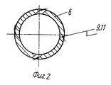
На фиг. 1 показан двигатель, общий вид, на фиг. 2 показана цилиндрическая стенка, разрез. In FIG. 1 shows an engine, a general view, and FIG. 2 shows a cylindrical wall, a section.
Двигатель содержит герметичную камеру 1, частично заполненную жидкостью и посредством пароподводящего трубопровода 2 сообщенную с парогенератором 3, подключенным к нижней части камеры 1 гидролинией 4 с установленным в ней перепускным клапаном 5, и размещенную в камере 1 гидротурбину с ротором 6, вращающимся под действием напора жидкости, вытесняемой паром, на наружной поверхности камеры 1 размещен теплообменник 7 системы охлаждения, ротор 6 гидротурбины выполнен в виде герметичного цилиндрического корпуса, верхняя стенка которого соединена с вертикальным валом 8 съема мощности, в его цилиндрической стенке выполнены тангенциальные щелевые каналы 9, а в нижней стенке впускные отверстия 10, в каналах 9 и отверстиях 10 установлены обратные клапаны 11, парогенератор 3 снабжен управляемым клапаном 12 и дополнительным трубопроводом 13, сообщающим парогенератор 3 через управляемый клапан 12 с верхней частью ротора 6, пароподводящий трубопровод 2 подключен к верхней части камеры 1 и через управляемый клапан 12 к парогенератору 3. The engine contains a sealed chamber 1, partially filled with liquid and by means of a steam supply pipe 2 communicated with a steam generator 3 connected to the lower part of the chamber 1 by a hydraulic line 4 with a bypass valve 5 installed in it, and a hydraulic turbine with a rotor 6 rotating in the chamber 1, which rotates under the action of a liquid pressure displaced by steam, on the outer surface of the chamber 1 is placed a heat exchanger 7 of the cooling system, the rotor 6 of the turbine is made in the form of a sealed cylindrical body, the upper wall of which is connected with a vertical shaft 8 for power removal, tangential slotted channels 9 are made in its cylindrical wall, and inlet holes 10 are installed in the lower wall, check valves 11 are installed in the channels 9 and holes 10, the steam generator 3 is equipped with a controlled valve 12 and an additional pipe 13 communicating the steam generator 3 through the controlled valve 12 with the upper part of the rotor 6, the steam supply pipe 2 is connected to the upper part of the chamber 1 and through the controlled valve 12 to the steam generator 3.
Двигатель работает следующим образом. The engine operates as follows.
В исходном состоянии жидкость (дистиллированная вода) частично заполняет герметичную камеру 1, ротор 6 и парогенератор 3. Управляемый клапан 12 и перепускной клапан 5 закрыты. В результате парообразования давление внутри парогенератора 3, нагретого от внешних источников, повышается. Управляя клапаном 12, осуществляется кратковременный доступ пара в камеру 1 через трубопровод 2. Трубопровод 13 находится в запертом состоянии. Давление в камере 1 повышается и жидкость через отверстие 10 вливается во внутреннюю полость ротора 6. Обратные клапаны 11 в щелевых каналах 9 закрыты. В результате конденсации пара давление в камере 1 падает. При этом, управляя клапаном 12, осуществляют кратковременный доступ пара, в верхнюю часть ротора 6 через трубопровод 13. Давление в верхней части ротора 6 увеличивается и жидкость с реактивной силой выбрасывается через тангенциальные щелевые каналы 9, что приводит во вращательное движение ротор 6 с валом 8. Далее в результате конденсации пара давление в верхней части ротора 6 падает и уравнивается с давлением в камере 1. При этом, если давление в камере 1 превышает давление в парогенераторе 3, то по гидролинии 4 через перепускной клапан 5 жидкость переливается в парогенератор 3 до выравнивания давлений. Далее рабочий цикл повторяется. Камера 1 будет охлаждаться в процессе работы установки теплообменником 7 системы охлаждения. In the initial state, the liquid (distilled water) partially fills the sealed chamber 1, the rotor 6 and the steam generator 3. The controlled valve 12 and the bypass valve 5 are closed. As a result of vaporization, the pressure inside the steam generator 3, heated from external sources, rises. By controlling the valve 12, the steam is briefly accessed into the chamber 1 through the pipe 2. The pipe 13 is in a locked state. The pressure in the chamber 1 rises and the fluid through the hole 10 is poured into the inner cavity of the rotor 6. The check valves 11 in the slotted channels 9 are closed. As a result of vapor condensation, the pressure in chamber 1 decreases. At the same time, controlling the valve 12, they provide short-term steam access to the upper part of the rotor 6 through the pipe 13. The pressure in the upper part of the rotor 6 increases and the fluid is reactively ejected through the tangential slotted channels 9, which rotates the rotor 6 with the shaft 8 Further, as a result of steam condensation, the pressure in the upper part of the rotor 6 drops and equalizes with the pressure in the chamber 1. In this case, if the pressure in the chamber 1 exceeds the pressure in the steam generator 3, then the liquid through line 4 through the bypass valve 5 erelivaetsya the steam generator 3 to the pressure equalization. Next, the work cycle is repeated. The chamber 1 will be cooled during operation of the installation by the heat exchanger 7 of the cooling system.
Claims (1)
Priority Applications (1)
| Application Number | Priority Date | Filing Date | Title |
|---|---|---|---|
| RU93029477A RU2070638C1 (en) | 1993-03-10 | 1993-03-10 | Engine |
Applications Claiming Priority (1)
| Application Number | Priority Date | Filing Date | Title |
|---|---|---|---|
| RU93029477A RU2070638C1 (en) | 1993-03-10 | 1993-03-10 | Engine |
Publications (2)
| Publication Number | Publication Date |
|---|---|
| RU93029477A RU93029477A (en) | 1996-03-20 |
| RU2070638C1 true RU2070638C1 (en) | 1996-12-20 |
Family
ID=20142691
Family Applications (1)
| Application Number | Title | Priority Date | Filing Date |
|---|---|---|---|
| RU93029477A RU2070638C1 (en) | 1993-03-10 | 1993-03-10 | Engine |
Country Status (1)
| Country | Link |
|---|---|
| RU (1) | RU2070638C1 (en) |
-
1993
- 1993-03-10 RU RU93029477A patent/RU2070638C1/en active
Non-Patent Citations (1)
| Title |
|---|
| Авторское свидетельство СССР N 842205, кл. F 01 K 11/00, 1981. * |
Similar Documents
| Publication | Publication Date | Title |
|---|---|---|
| US4738111A (en) | Power unit for converting heat to power | |
| US4183220A (en) | Positive displacement gas expansion engine with low temperature differential | |
| ES2197194T3 (en) | TWO PHASE HYBRID TURBINE. | |
| JPS58500448A (en) | Closed turbine generator | |
| RU2004128453A (en) | METHOD AND DEVICE FOR COOLING SEALS FOR MACHINERY | |
| US7913493B2 (en) | Rotary displacement steam engine | |
| RU2070638C1 (en) | Engine | |
| JP3219179U (en) | Multiple impeller turbine generator | |
| RU2056606C1 (en) | Heat energy-to-mechanical work converter | |
| RU2450218C2 (en) | Steam compression plant | |
| JP4735116B2 (en) | Rotary steam engine | |
| US4307573A (en) | Thermal-cycle engine | |
| RU2053375C1 (en) | Self-contained power supply source | |
| GB701511A (en) | Improvements in and relating to pump and motor combinations | |
| RU61852U1 (en) | DRIVING CAVITATION HEAT AND STEAM GENERATOR | |
| RU2053376C1 (en) | Electric power plant | |
| JPS5990710A (en) | Gas motor | |
| RU2017978C1 (en) | Safety rotary engine reactor | |
| RU2113598C1 (en) | Steam plant | |
| RU2371612C1 (en) | Heat-tube pump | |
| CN1952385A (en) | Rotary-shaft water-feeding type water turbine | |
| SU842205A1 (en) | Heat engine | |
| SU1719663A1 (en) | Steam-power plant | |
| RU134239U1 (en) | CENTRAL WET-WET STEAM TURBINE | |
| RU1697481C (en) | Steam power plant |