RU131425U1 - MAIN PUMPING STATION OF THE OIL-PUMPING TECHNOLOGICAL SECTION - Google Patents
MAIN PUMPING STATION OF THE OIL-PUMPING TECHNOLOGICAL SECTION Download PDFInfo
- Publication number
- RU131425U1 RU131425U1 RU2013104722/06U RU2013104722U RU131425U1 RU 131425 U1 RU131425 U1 RU 131425U1 RU 2013104722/06 U RU2013104722/06 U RU 2013104722/06U RU 2013104722 U RU2013104722 U RU 2013104722U RU 131425 U1 RU131425 U1 RU 131425U1
- Authority
- RU
- Russia
- Prior art keywords
- pressure
- pump
- outlet
- manifold
- input
- Prior art date
Links
Images
Landscapes
- Control Of Positive-Displacement Pumps (AREA)
Abstract
Магистральная насосная станция нефтеперекачивающего технологического участка, содержащая группу насосов, связанных с электродвигателями, входы и выходы насосов сообщены с коллектором, связанным на входе и выходе с магистральным трубопроводом, и систему управления, имеющую датчики давления соответственно на входе и выходе из коллектора, выходы упомянутых датчиков давления связаны с первыми входами соответственно блока сравнения по входному давлению и блока сравнения по выходному давлению из коллектора, причем второй вход блока сравнения по входному давлению связан с задатчиком сигнала, соответствующего минимальному давлению, обусловленному величиной давления бескавитационного режима работы насоса, а второй вход блока сравнения по выходному давлению связан с задатчиком сигнала, соответствующего максимальному давлению, обусловленному прочностными свойствами магистрального трубопровода, отличающаяся тем, что каждый электродвигатель связан с насосом через гидромуфту, имеющую систему ее заполнения рабочей средой, выполненную с регулируемым насосом, элемент управления которым связан с выходом блока управления с возможностью изменения давления на выходе насоса по параметрам давления на входе и выходе коллектора.The main pumping station of the oil pumping technological section, containing a group of pumps associated with electric motors, the pump inlets and outlets are connected to a manifold connected at the inlet and outlet of the main pipeline, and a control system having pressure sensors respectively at the inlet and outlet of the manifold, outputs of said sensors pressures are connected to the first inputs of the comparison unit for input pressure and the unit for comparison for output pressure from the manifold, the second input of the comp input pressure is connected to a signal setter corresponding to the minimum pressure caused by the pressure of the cavitation-free mode of operation of the pump, and the second input of the output pressure comparison unit is connected to a signal setter corresponding to the maximum pressure due to the strength properties of the main pipeline, characterized in that each electric motor connected to the pump through a fluid coupling having a system for filling it with a working medium, made with an adjustable pump, control element Lenia which is connected with the output of the control unit with the possibility of changing the pressure at the pump outlet to the pressure parameters at the inlet and outlet manifold.
Description
Полезная модель относится к нефтепроводному оборудованию, а именно к магистральным насосным станциям нефтеперекачивающего технологического участка, в частности к устройствам регулированию расхода нефтепродуктов, транспортируемых по магистральному нефтепроводу.The utility model relates to oil pipeline equipment, namely, to main pumping stations of an oil pumping technological section, in particular to devices for regulating the flow of oil products transported through a main oil pipeline.
Из уровня техники известны различные решения, связанные с выполнением магистральных насосных станций нефтеперекачивающего технологического участка, см. Насосная станция, содержащая насосные агрегаты со всасывающими и нагнетательными трубопроводами и запорной арматурой, систему маслоснабжения, включающую маслонасос, бак и маслопроводы для смазки и охлаждения подшипников насосных агрегатов, при этом насосная станция размещена на открытой площадке, при этом бак и маслопроводы выполнены с электрообогревом, а запорная арматура расположена непосредственно у насосных агрегатов. Патент РФ на полезную модель RU45485 от 10.05.2005 F15B1/02, F04B23/00.Various solutions are known from the prior art related to the implementation of the main pumping stations of the oil pumping technological section, see Pumping station containing pumping units with suction and discharge pipelines and valves, an oil supply system including an oil pump, a tank and oil pipelines for lubricating and cooling bearings of pumping units while the pumping station is located on an open area, while the tank and oil pipelines are electrically heated, and the shutoff valves are located directly at the pump units. RF patent for utility model RU45485 dated 05/10/2005 F15B1 / 02, F04B23 / 00.
В качестве ближайшего аналога принята магистральная насосная станция, описанная в книге «Трубопроводный транспорт нефти», Г.Г.Васильев и др., М.,2002, с.157-163, рис.7.3 (в). Известная насосная станция магистральной насосной станции представляет собой группу насосов с электропиводами, входы и выходы которых сообщены с коллектором 4, связанным на входе и выходе с магистральным трубопроводом 12. Для обеспечения поддержания на выходе из коллектора требуемого согласно заданным параметрам системы давления нефти насосная станция оборудована регулируемой дроссельной системой, имеющей датчики давления соответственно на входе и выходе из коллектора, выходы упомянутых датчиков давления связаны с первыми входами соответственно блока сравнения по входному давлению и блока сравнения по выходному давления из коллектора, причем второй вход блока сравнения по входному давлению связан с задатчиком сигнала минимального давления, обусловленного величиной давления бескавитационного режима работы насоса, а второй вход блока сравнения по выходному давлению связан с задатчиком сигнала максимального давления, обусловленного прочностными свойствами магистрального трубопровод.The main pumping station described in the book “Pipeline Transport of Oil”, G.G. Vasiliev et al., M., 2002, p. 157-163, Fig. 7.3 (c), was adopted as the closest analogue. The well-known pump station of the main pump station is a group of pumps with electric drives, the inputs and outputs of which are connected to the collector 4, connected at the inlet and outlet of the
К недостаткам известных устройств относится то, что применение дроссельной системы изменения давления в магистральном трубопроводе после насосной станции, с одной стороны поглощает путем дросселирования энергию потока нефти, а главное не использует возможности насосной установки, позволяющие увеличить напор на выходе на 15-20% в связи с тем, что при регулировании давление в коллекторе магистральной насосной станции выше давления на выходе дросселя.The disadvantages of the known devices include the fact that the use of a throttle system for changing the pressure in the main pipeline after the pump station, on the one hand, absorbs the energy of the oil flow by throttling, and most importantly does not use the capabilities of the pump installation, which can increase the pressure at the outlet by 15-20% in connection so that when regulating the pressure in the manifold of the main pumping station is higher than the pressure at the outlet of the throttle.
Задачей, на решение которой направлена полезная модель, является снижение количества насосных станций при условии обеспечения постоянной производительности нефтеперекачивающего технологического участка (или увеличение производительности нефтеперекачивающего технологического участка при сохранении количества на этом участке насосных станций).The problem the utility model is aimed at is to reduce the number of pumping stations, provided that the productivity of the oil pumping technological section is constant (or increase the productivity of the oil pumping technological section while maintaining the number of pumping stations in this section).
Технический результат заключается в повышении давления нефти на выходе магистральной насосной станции до максимально допустимого давления для насосного оборудования станции (МНС) путем обеспечения регулирования частоты вращения вала насоса при помощи применения управляемой гидродинамической муфты, установленной между электродвигателем и насоса для перекачки нефти, и выполненной с управляемой системой ее наполнения рабочей средой с возможностью обеспечения изменения частоты вращения насоса по перекачки нефти.The technical result consists in increasing the oil pressure at the outlet of the main pumping station to the maximum allowable pressure for the pumping equipment of the station (MHF) by providing control of the rotational speed of the pump shaft by using a controlled hydrodynamic coupling installed between the electric motor and the pump for pumping oil, and made with controlled a system for filling it with a working medium with the possibility of changing the speed of the pump for pumping oil.
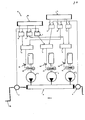
Согласно полезной модели указанный технический результат достигается тем, что в магистральной насосной станции нефтеперекачивающего технологического участка, содержащей группу насосов 2, связанных с электродвигателями 3, входы и выходы насосов сообщены с коллектором 4, связанным на входе и выходе с магистральным трубопроводом 12, и систему управления, имеющую датчики давления 5,6 соответственно на входе и выходе из коллектора 4, выходы упомянутых датчиков давления 5,6 связаны с первыми входами соответственно блока сравнения 7 по входному давлению и блока сравнения 8 по выходному давления из коллектора, причем второй вход блока сравнения 7 по входному давлению связан с задатчиком 10 сигнала, соответствующего минимальному давлению, обусловленному величиной давления бескавитационного режима работы насоса, а второй вход блока сравнения 8 по выходному давлению связан с задатчиком 11 сигнала, соответствующего максимальному давлению, обусловленному прочностными свойствами магистрального трубопровода 12, каждый электродвигатель 3 связан с насосом через гидромуфту 13, имеющую систему ее заполнения рабочей средой, выполненную регулируемым насосом 14, элемент управления которым связан с выходом блока управления 9 с возможностью изменения давления на выходе насоса по параметрам давления на входе и выходе коллектора 4.According to a utility model, the indicated technical result is achieved by the fact that in the main pumping station of the oil pumping technological section containing a group of
Указанные признаки являются существенными и взаимосвязанными между собой причинно-следственной связью с образованием совокупности существенных признаков, достаточных для достижения технического результата, касающегося, в частности, увеличения производительности нефтеперекачивающего технологического участка при сохранении количества насосных станций на этом участке.The indicated features are essential and interconnected causally with the formation of a set of essential features sufficient to achieve a technical result relating, in particular, to increase the productivity of the oil pumping technological section while maintaining the number of pumping stations in this section.
Сущность полезной модели подробно представлена на чертеже:The essence of the utility model is presented in detail in the drawing:
Полезная модель поясняется конкретным примером выполнения, который, однако, не является единственно возможным, но наглядно демонстрирует возможность достижения данной совокупностью существенных признаков заданного технического результата.The utility model is illustrated by a specific implementation example, which, however, is not the only possible, but clearly demonstrates the possibility of achieving this set of essential features of a given technical result.
Раскрытие сущности магистральной насосной станции поясняется позициями, изображенными на чертеже:The disclosure of the essence of the main pumping station is illustrated by the positions depicted in the drawing:
поз.1 - магистральной насосной станции;Pos. 1 - main pumping station;
поз.2 - насос, предназначенный для перекачивания нефти, выполненный центробежным и кинематически связанный с электроприводом и своими входом и выходом сообщенный коллектором;pos.2 - a pump designed for pumping oil, made by centrifugal and kinematically connected to the electric drive and its input and output communicated by the collector;
поз.3 - электродвигатель;Pos. 3 - electric motor;
поз.4 - коллектор, сообщенный на входе и выходе с магистральным трубопроводом 12;Pos.4 - collector communicated at the inlet and outlet with the
поз.5 - датчик давления, установленный на входе в коллектор;pos.5 - pressure sensor installed at the inlet to the manifold;
поз.6 - датчик давления, установленный на выходе в коллектор;pos.6 - pressure sensor installed at the outlet of the manifold;
поз.7 - блока сравнения по входному давлению;pos.7 - block comparison by input pressure;
поз.8 - блока сравнения по выходному давлению;pos.8 - block comparison of the output pressure;
поз.9 - блок управления, для выработки управляющего сигнала в систему заполнения гидромуфты рабочей средой;Pos. 9 - control unit for generating a control signal to the fluid coupling system of the fluid;
поз.10 - задатчик сигнала, соответствующего минимальному давлению, обусловленному величиной давления бескавитационного режима работы насоса;Pos.10 - signal generator corresponding to the minimum pressure due to the pressure of the cavitation-free pump operation mode;
поз.11 - задатчик сигнала, соответствующего максимальному давлению, обусловленному прочностными свойствами магистрального трубопровода 12;POS.11 - the signal setter corresponding to the maximum pressure due to the strength properties of the
поз.12 - магистрального трубопровода;pos.12 - the main pipeline;
поз.13 - гидромуфта, установленная между электродвигателем 3 и насосом 2 и выполненная с системой ее заполнения, обеспечивающей плавный запуск и варьирование скоростью насоса;Pos.13 - a fluid coupling installed between the
поз.14 - регулируемый гидронасос заполнения гидромуфты рабочей средой.Pos. 14 - an adjustable hydraulic pump for filling a fluid coupling with a working medium.
Согласно полезной модели магистральная насосная станция 1 нефтеперекачивающего технологического участка содержит группу насосов 2, связанных через гидромуфты с электродвигателями 3. Входы и выходы насосов 2 сообщены с коллектором 4, связанным на входе и выходе с магистральным трубопроводом 12. Кроме этого, станция 1 содержит систему управления, выполненную на основе ПИД-регулятора и имеющую датчики давления 5, 6 соответственно на входе и выходе из коллектора 4, выходы упомянутых датчиков давления 5, 6 связаны с первыми входами соответственно блока сравнения 7 по входному давлению и блока сравнения 8 по выходному давления из коллектора.According to a utility model, the
При этом второй вход блока сравнения 7 по входному давлению связан с задатчиком 10 сигнала, соответствующего минимальному давлению, обусловленному величиной давления бескавитационного режима работы насоса, а второй вход блока сравнения 8 по выходному давлению связан с задатчиком 11 сигнала, соответствующего максимальному давлению, обусловленному прочностными свойствами магистрального трубопровода 12. Оба задатчика 10 и 11 сигналов функционируют по одному принципу:In this case, the second input of the comparison unit 7 by the input pressure is connected to the
регулирование осуществляется сравнением текущего значения измеряемой физической величины с заданным значением (уставкой), обеспечивая устранение рассогласования (ошибки, вызванной внешним воздействием на объект регулирования или ошибки, вызванной изменением значения уставки).regulation is carried out by comparing the current value of the measured physical quantity with a predetermined value (setpoint), ensuring the elimination of the mismatch (an error caused by an external influence on the regulation object or an error caused by a change in the setpoint value).
Применительно к нашему случаю в качестве уставки регулирования выступает постоянное значение, которое может быть задано с клавиатуры регулятора или дистанционно: через дополнительный аналоговый вход либо через цифровой порт связи (все типы регуляторов).In our case, a constant value acts as a control setpoint, which can be set from the controller keyboard either remotely: via an additional analog input or through a digital communication port (all types of controllers).
Особенностью решения является то, что каждый электродвигатель 3 связан с насосом 2 для перекачки нефти через гидромуфту 13, имеющую систему управления ее заполнения рабочей средой, выполненную с регулируемым насосом 14, элемент управления которым связан с выходом блока управления 9 с возможностью изменения давления на выходе насоса по параметрам давления на входе и выходе коллектора 4.A feature of the solution is that each
Предложенная полезная модель функционирует следующим образом.The proposed utility model operates as follows.
Текущие значения давлений на входе и выходе коллектора 4 контролируются устройствами в виде датчиков 5, 6 давления с передачей показаний в систему управления нефтеперекачивающей станции. При этом в процессе управления работой системы заполнения гидромуфты 13 рабочей средой решается главная задача недопущение превышения давления на выходе магистральной насосной станции выше заданного значения давления, соответствующего уставке регулирования на выходе коллектора 4, и недопущение снижения давления на входе в магистральную насосную станцию ниже заданного значения давления, соответствующего уставке регулирования на входе в коллектор 4.The current values of the pressures at the inlet and outlet of the manifold 4 are controlled by devices in the form of
После сопоставления в блоках 7 и 8 сравнения сигналов, поступающих от датчиков давлений 5, 6 и задатчиков 10, 11, формируются сигналы, направляемые в блоки управления 9 для формирования управляющего воздействия на систему управления заполнением гидромуфты 13. Такое управление осуществляется с помощью программного модуля «ПИД-регулятор», осуществляющий получение текущих значений давлений на входе и выходе в коллектор 4 магистральной насосной станции и заданных уставок регулирования от задатчиков 10 и 11.After comparing in blocks 7 and 8 a comparison of the signals received from the
Так, в случае увеличения давления на выходе в коллектор 4 выше заданного значения, либо при снижении давления на входе коллектор 4 ниже заданного значения вырабатывается сигнал, поступающий на снижение объема наполнения гидромуфты рабочей, и как следствие на изменение режима работы насоса по перекачки нефти.So, in the case of an increase in the pressure at the outlet to the collector 4 above a predetermined value, or when the pressure at the inlet of the collector 4 decreases below a predetermined value, a signal is generated that is used to reduce the filling volume of the hydraulic fluid coupling and, as a result, to change the operating mode of the pump for pumping oil.
В случае, если давление на входе в коллектор 4 выше уставки, заданной задатчиком 10, а давление на выходе коллектора 4 ниже уставки, заданной задатчиком 11, причем напор на выходе насоса 2 также низкий, то система управления, в основу которой положен ПИД-регулятор, формирует управляющий сигнал на элемент управления гидронасосом 14 для изменения заполнения гидромуфты рабочей средой с последующим изменением производительности насоса 2 по перекачиванию нефти и устранением одного из вышеперечисленных условий.If the pressure at the inlet to the collector 4 is higher than the setpoint set by the
Изменение частоты вращения выходного вала гидромуфты МНА осуществляется с помощью использования гидронасоса заполнения гидромуфты 13 рабочей средой, при этом регулирование давления на входе и выходе магистральной насосной станции с помощью гидродинамической муфты наиболее эффективно, когда в процессе перекачки нефти требуется обеспечить плавный пуск МНА при относительно небольшом диапазоне регулирования технологических режимов по давлению, что в итоге не приводит к снижению коэффициента полезного действия насосной станции.The change in the rotational speed of the output shaft of the MHA fluid coupling is carried out by using a hydraulic pump to fill the
При сопоставлении предложенного решения с прототипом получается следующее. В процессе дросселирования перед регулятором давления (у прототипа) формируется давление, превышающее давление на выходе нефтеперекачивающей станции, так называемое «коллекторное» давление. Величина «коллекторного» давления может составлять до 7,5 МПа и ограничена возможностями производителей насосного оборудования серийных магистральных насосов. Учитывая, что величина увеличения «коллекторного» давления составляет 1,0 - 1,5 МПа, допустимое рабочее давление на выходе нефтеперекачивающей станции принята не более 6,3 МПа.When comparing the proposed solution with the prototype, the following is obtained. During throttling, a pressure is formed in front of the pressure regulator (in the prototype), which exceeds the pressure at the outlet of the oil pumping station, the so-called “collector” pressure. The value of the “collector” pressure can be up to 7.5 MPa and is limited by the capabilities of the manufacturers of pumping equipment for serial main pumps. Given that the magnitude of the increase in “collector” pressure is 1.0 - 1.5 MPa, the permissible working pressure at the outlet of the oil pumping station is adopted no more than 6.3 MPa.
В случае регулирования давления методом изменения числа оборотов магистрального насоса 2 с помощью гидромуфты, давление в коллекторе МНС не превышает давление на ее выходе. В связи с этим, при проектировании имеется возможность повысить допустимое давление на выходе магистральной насосной станции до 7,5 МПа.In the case of pressure control by changing the speed of the
Данное решение позволяет при проектировании уменьшить требуемое количество нефтеперекачивающих станций по трассе нефтепровода по сравнению с вариантом регулирования давления методом дросселирования потока нефти, либо при одинаковом количестве нефтеперекачивающих станции по трассе магистрального нефтепровода обеспечит большую пропускную его способность.This solution allows designing to reduce the required number of oil pumping stations along the pipeline route in comparison with the pressure control method by throttling the oil flow, or with the same number of oil pumping stations along the main pipeline route, will provide a large throughput.
Таким образом применение полезной модели позволяет обеспечить увеличение производительности нефтеперекачивающего технологического участка при сохранении количества на этом участке насосных станций. При этом увеличение давления потока нефти на выходе магистральной насосной станции до максимально допустимого давления, рассчитанного для данного насосного оборудования станции, не меняя ее конструкции по существу, позволяет исключить из процесса управления использование накопительных резервуаров с системой насосов подпитки и перекачки, связанных трубопроводами с магистральным трубопроводом. Кроме этого, применение регулируемых гидромуфт существенно для оперативного изменения частоты вращения центробежных насосов при переменных нагрузках. При снижении нагрузки гидромуфта уменьшает частоту вращения насоса, что существенно улучшает его работу и продляет срок службы.Thus, the application of the utility model allows to increase the productivity of the oil pumping technological section while maintaining the number of pumping stations in this section. In this case, an increase in the pressure of the oil flow at the outlet of the main pumping station to the maximum allowable pressure calculated for this pumping equipment of the station, without essentially changing its design, allows us to exclude the use of storage tanks with a system of charge and transfer pumps connected by pipelines to the main pipeline from the control process . In addition, the use of adjustable fluid couplings is essential for the operational change of the rotational speed of centrifugal pumps at variable loads. When reducing the load of the fluid coupling reduces the speed of the pump, which significantly improves its operation and prolongs its service life.
Claims (1)

Priority Applications (1)
| Application Number | Priority Date | Filing Date | Title |
|---|---|---|---|
| RU2013104722/06U RU131425U1 (en) | 2013-02-06 | 2013-02-06 | MAIN PUMPING STATION OF THE OIL-PUMPING TECHNOLOGICAL SECTION |
Applications Claiming Priority (1)
| Application Number | Priority Date | Filing Date | Title |
|---|---|---|---|
| RU2013104722/06U RU131425U1 (en) | 2013-02-06 | 2013-02-06 | MAIN PUMPING STATION OF THE OIL-PUMPING TECHNOLOGICAL SECTION |
Publications (1)
| Publication Number | Publication Date |
|---|---|
| RU131425U1 true RU131425U1 (en) | 2013-08-20 |
Family
ID=49163189
Family Applications (1)
| Application Number | Title | Priority Date | Filing Date |
|---|---|---|---|
| RU2013104722/06U RU131425U1 (en) | 2013-02-06 | 2013-02-06 | MAIN PUMPING STATION OF THE OIL-PUMPING TECHNOLOGICAL SECTION |
Country Status (1)
| Country | Link |
|---|---|
| RU (1) | RU131425U1 (en) |
-
2013
- 2013-02-06 RU RU2013104722/06U patent/RU131425U1/en active
Similar Documents
| Publication | Publication Date | Title |
|---|---|---|
| US20180266412A1 (en) | Plant for controlling delivery of pressurized fluid in a conduit, and a method of controlling a prime mover | |
| US20130004337A1 (en) | System and method for driving a pump | |
| EP3020941A1 (en) | Aircraft fuel system | |
| RU2551139C1 (en) | Pump station electric drive automatic control method | |
| CN106808658B (en) | Temperature control device | |
| CN106499005A (en) | A kind of water supply pump station feedback control system | |
| RU2647288C1 (en) | Method for automatic control of technological process for supply of gas condensate into main condensate line | |
| CN102367793A (en) | Efficient method and pump valve integrated energy-saving device for water pump | |
| RU2561782C1 (en) | Method of energy efficiency increasing of pump station | |
| KR101602475B1 (en) | The optimal control method of inverter booster pump | |
| CN110107525B (en) | A kind of control method of system pressure of centrifugal air compressor station | |
| RU131425U1 (en) | MAIN PUMPING STATION OF THE OIL-PUMPING TECHNOLOGICAL SECTION | |
| CN107044458B (en) | A kind of ropeway fluid power system using accumulator pressure regulation | |
| RU2493361C1 (en) | Method for controlling multimachine complex of reservoir pressure maintenance system | |
| CN105156376A (en) | Closed hydraulic servo loading system, hydraulic device and loading device | |
| RU131429U1 (en) | MAIN PUMPING STATION OF THE OIL-PUMPING TECHNOLOGICAL SECTION | |
| US20100268389A1 (en) | System and method for regulating a flow of liquid | |
| CA2836304C (en) | Method and system of recovering energy from a flow of oil sands slurry | |
| RU2310792C1 (en) | Method to control power consumption of pumping plant | |
| CN201513358U (en) | High-speed centrifugal pump flow regulation and pump-automatic switching system | |
| US9525375B2 (en) | Oil sand slurry transportation system and method for variable slurry flow rates | |
| JP2020502411A (en) | Flow controller | |
| CN206929146U (en) | A kind of ropeway fluid power system using accumulator pressure regulation | |
| CN101012826A (en) | Self-controlled pressure-sustaining oil transmission pump set | |
| CN207161405U (en) | A kind of novel continuous oil pipe equipment injection head motor-driven system |
Legal Events
| Date | Code | Title | Description |
|---|---|---|---|
| PD1K | Correction of name of utility model owner |