KR930002752B1 - How to display the message on the pager receiver - Google Patents
How to display the message on the pager receiver Download PDFInfo
- Publication number
- KR930002752B1 KR930002752B1 KR1019880012637A KR880012637A KR930002752B1 KR 930002752 B1 KR930002752 B1 KR 930002752B1 KR 1019880012637 A KR1019880012637 A KR 1019880012637A KR 880012637 A KR880012637 A KR 880012637A KR 930002752 B1 KR930002752 B1 KR 930002752B1
- Authority
- KR
- South Korea
- Prior art keywords
- message
- time
- displaying
- display
- received
- Prior art date
- Legal status (The legal status is an assumption and is not a legal conclusion. Google has not performed a legal analysis and makes no representation as to the accuracy of the status listed.)
- Expired - Fee Related
Links
Images


Classifications
-
- H—ELECTRICITY
- H04—ELECTRIC COMMUNICATION TECHNIQUE
- H04B—TRANSMISSION
- H04B1/00—Details of transmission systems, not covered by a single one of groups H04B3/00 - H04B13/00; Details of transmission systems not characterised by the medium used for transmission
- H04B1/06—Receivers
-
- G—PHYSICS
- G08—SIGNALLING
- G08B—SIGNALLING SYSTEMS, e.g. PERSONAL CALLING SYSTEMS; ORDER TELEGRAPHS; ALARM SYSTEMS
- G08B5/00—Visible signalling systems, e.g. visible personal calling systems or remote indication of seats occupied
- G08B5/22—Visible signalling systems, e.g. visible personal calling systems or remote indication of seats occupied using electric transmission; using electromagnetic transmission
- G08B5/222—Personal calling arrangements or devices, i.e. paging systems
- G08B5/223—Personal calling arrangements or devices, i.e. paging systems using wireless transmission
- G08B5/224—Paging receivers with visible signalling details
- G08B5/225—Display details
-
- H—ELECTRICITY
- H04—ELECTRIC COMMUNICATION TECHNIQUE
- H04B—TRANSMISSION
- H04B7/00—Radio transmission systems, i.e. using radiation field
- H04B7/24—Radio transmission systems, i.e. using radiation field for communication between two or more posts
- H04B7/26—Radio transmission systems, i.e. using radiation field for communication between two or more posts at least one of which is mobile
Landscapes
- Engineering & Computer Science (AREA)
- Computer Networks & Wireless Communication (AREA)
- Physics & Mathematics (AREA)
- Electromagnetism (AREA)
- General Physics & Mathematics (AREA)
- Signal Processing (AREA)
- Mobile Radio Communication Systems (AREA)
Abstract
내용 없음.No content.
Description
제 1 도는 본 발명을 수행하기 위한 페이저수신기의 블럭도.1 is a block diagram of a pager receiver for carrying out the present invention.
제 2 도는 메세지 수신시 처리흐름도.2 is a flow diagram of processing a message.
제 3 도는 키 입력에 의한 메세지처리흐름도.3 is a flow chart of message processing by key input.
제 4 도는 메세지 수신시 메세지 및 상태 표시 타이밍도.4 is a timing diagram of message and status indication upon receipt of a message.
제 5 도는 키 입력시 저장 메모리의 표시 타이밍도.5 is a display timing diagram of a storage memory when a key is pressed.
제 6 도는 페이저수신기의 상태 정보 표시도.6 is a state information display diagram of a pager receiver.
제 7 도는 메모리 어드레스 표시도.7 is a memory address display diagram.
* 도면의 주요부분에 대한 부호의 설명* Explanation of symbols for main parts of the drawings
1 : 안테나 2 : RF수신부1
3 : 파형정형부 4 : 마이컴3: waveform shaping part 4: microcomputer
5 : 롬 6 : 경보구동부5: Rom 6: Alarm Drive
7 : 스피커 8 : 표시부7 speaker 8 display unit
9 : 키입력부 10 : 상태표시부9: key input unit 10: status display unit
본 발명은 페이저수신기의 메세지 표시방법에 관한 것으로, 특히 페이저수신기의 모드에 따라 해당하는 상태 정보 및 메세지 정보를 표시할 수 있는 방법에 관한 것이다.The present invention relates to a message display method of a pager receiver, and more particularly, to a method capable of displaying corresponding status information and message information according to a mode of a pager receiver.
일반적으로 페이저수신기(paper reveiver)는 소형이므로, 메세지 및 상태를 표시하는 표시부(Liquid Crystal Display)는 12디지트의 데이타를 표시할 수 있으며, 메모리 어드레스를 지시하기 위한 메모리 인디케이터(memory indicator)를 사용하고 있다.In general, the paper reveiver is small, so the Liquid Crystal Display can display 12 digits of data and uses a memory indicator to indicate the memory address. have.
그러나 수신된 메세지의 메모리 정보가 증가될 경우 각 메모리의 어드레스를 표시하는 인디케이터 때문에 표시부의 메세지 표시용 세그먼트(Segment) 크기에 제한을 받게 되었으며, 또한 상기 메모리 인디케이터가 너무 작아 사용자가 쉽게 인식하기 어려운 문제점등이 있었다.However, when the memory information of the received message is increased, the indicator for displaying the address of each memory is limited by the size of the message display segment, and the memory indicator is too small to be easily recognized by the user. There was a back.
따라서 본 발명의 목적은 페이저수신기에서 표시부 상에 메세지 및 상태정보를 효과적으로 표시할 수 있는 방법을 제공함에 있다.Accordingly, an object of the present invention is to provide a method for effectively displaying a message and status information on a display unit in a pager receiver.
본 발명의 다른 목적은 페이저수신기에서 메세지 수신 모드시 해당하는 메세지를 표시하며, 메세지 표시후 저장된 메세지의 수 또는 읽혀지지 않은 메세지의 수를 콜링정보로 표시할 수 있는 방법을 제공함에 있다.Another object of the present invention is to provide a method for displaying a corresponding message in a message receiving mode in a pager receiver and displaying the number of stored messages or the number of unread messages as calling information after displaying the message.
본 발명의 또 다른 목적은 페이저수신기에서 대기 모드시 저장된 메세지 수 또는 읽혀지지 않은 메세지의 수를 표시하며, 소정 키 신호 발생시 해당 키신호가 발생되는 동안 소정 시간 주기로 상기 메세지들을 억세스하여 순차적으로 표시할 수 있는 방법을 제공함에 있다.Another object of the present invention is to display the number of stored messages or unread messages in the standby mode in the pager receiver, and when the predetermined key signal is generated, the messages are sequentially accessed by accessing the messages at predetermined time periods while the corresponding key signal is generated. It is to provide a way to.
이하 본 발명을 도면을 참조하여 상세히 설명한다.Hereinafter, the present invention will be described in detail with reference to the drawings.
제 1 도는 본 발명을 수행하기 위한 페이저수신기 블럭도로서, 안테나(1)와 연결되며, 상기 안테나(1)을 통해 수신되는 RF변조신호를 증폭, 주파수변환 및 복조하는 RF수신부(2)와, 상기 RF수신부(2)와 연결되며, 상기 RF수신부(2)를 출력하는 복조신호를 여파한 후 2치화 신호의 디지탈 형태로 파형정형하는 파형정형부(3)과, 해당 페이저수신기의 데이타를 판별해 내기 위한 자기 고유의 어드레스데이타 및 프레임데이타를 저장하고 있는 메모리(5)와, 상기 파형정형부(3)의 출력단과 연결되며, 상기 파형정형부(3)으로 부터 데이타가 수시될 시 상기 메모리(5)에 저장하고 있는 자기어드레스데이타와 비교하여 수신되는 데이타가 자기 데이타인가를 판별하고 자기데이타인 경우 경보신호를 발생하며, 리드키 수신시 현 모드의 지정 상태에 저장중인 데이타를 표시하도록 제어하는 마이컴(4)과, 상기 마이컴(4)의 경보신호 출력단과 스피커(7) 사이에 연결되며, 상기 마이컴(4)로 부터 경보신호 수신시 상기 스피커(7)을 통해 경보음을 발생하는 경보구동부(6)와, 상기 마이컴(4)의 표시데이타 출력단과 연결되며, 상기 마이컴(4)로 부터 메세지 및 콜링정보에 해당하는 표시데이타 수신시 이를 표시하는 표시부(8)와, 리드키 및 사이런트키 등으로 이루어지며, 저장메세지를 표시하기 위한 리드키신호 및 경보음의 발생을 차단하기 위한 사일런트키신호를 발생하여 상기 마이컴(4)로 출력하는 키입력부(9)와, 상기 마이컴(4)의 제어하에 페이저수신기의 상태를 표시하는 상태구동부(10)로 구성된다.1 is a block diagram of a pager receiver for carrying out the present invention, which is connected to an antenna 1, an
제 2 도는 본 발명에 따라 페이저수신기에서 수신된 메세지 및 콜링정보(Calling information)를 표시하는 흐름도로서, 자기 메세지의 수신 유무를 검사하는 과정과, 상기 수신되는 자기 메세지를 저장하고 일정시간 동안 경보신호를 발생하는 동시에 수신된 자기메세지를 표시하는 과정과, 상기 경보구동시간 경과후 일정시간 동안 경보신호의 송출을 중단하고 수신된 메세지를 표시하는 과정과, 상기 메세지표시시간 경과후 콜링정보를 표시하는 과정과, 상기 경보구동시간이 경과하기 전에 소정의 키신호가 수신될시 경보신호의 송출을 중단하고 메세지표시시간동안 수신된 메세지를 표시하고 상기 콜링정보 표시과정으로 진행하는 과정으로 이루어진다.2 is a flowchart showing a message and calling information received by a pager receiver according to the present invention, a process of checking whether a magnetic message is received, storing the received magnetic message, and storing an alarm signal for a predetermined time. Displaying a received message at the same time as generating a message, stopping the transmission of an alarm signal for a predetermined time after the elapse of the alarm driving time, displaying a received message, and displaying calling information after the elapse of the message display time. And stopping the transmission of the alarm signal when the predetermined key signal is received before the alarm drive time elapses, displaying the received message during the message display time, and proceeding to the calling information display process.
제 3 도는 메세지가 수신되고 있지 않는 대기 상태에서 리드키 발생시 메모리에 저장하고 있는 메세지를 표시하는 흐름도로서, 리드키의 눌림 여부를 검사하는 과정과, 상기 리드키 수신시 상기 메모리로 부터 표시할 메세지의 어드레스를 표시하는 과정과, 상기 메세지 어드레스 표시상태에서 상기 리드키 해제시 제 1 메세지표시시간 동안 해당하는 메세지를 표시하는 과정과, 상기 제 1 메세지표시시간 경과 후 콜링정보를 표시하는 과정과, 상기 메세지 어드레스 표시 종료시 까지 상기 리드키가 수신될 시 상기 메모리에 저장하고 있는 메세지들을 제 2 메세지표시시간 주기로 리드하여 순차적으로 표시하는 과정과, 상기 메세지표시과정에서 상기 리드키 해제시 상기 현 표시중인 메세지를 상기 제 1 메세지표시시간 동안 표시하고 콜링정보 표시 과정으로 진행하는 과정으로 이루어진다.3 is a flowchart showing a message stored in a memory when a lead key is generated in a standby state in which no message is being received, and a process of checking whether the lead key is pressed and a message to be displayed from the memory when the lead key is received. Displaying a corresponding address, displaying a corresponding message during a first message display time when the lead key is released in the message address display state, displaying calling information after the first message display time has elapsed; Reading the messages stored in the memory in a second message display time period when the read key is received until the message address display ends, and sequentially displaying the read keys; A message is displayed during the first message display time and the calling information display and It consists of a process proceeds.
제 4 도는 메세지 수신시 경보음 및 메세지를 표시하는 타이밍도로서, 4a는 메세지 수신시 경보구동시간(이하 "T1시간"이라 칭함) 동안 스피커(7)를 통해 경보음(alert tone)을 발생하는 동시에 표시부(8)를 통해 상대방(즉 발신측)에서 전송한 메세지를 표시하고, 이후 상기 T1시간이 종료되면 스피커(7)을 통해 출력되던 경보음의 구동을 중지하고 표시부(8)상의 메세지는 메세지표시시간(이하 "T2시간"이라 칭함) 동안 계속 표시한다. 상기 T1시간 및 T2시간이 지나면 표시부(8)상에 메세지의 표시를 중단하고 콜링정보를 표시한다.4 is a timing diagram for displaying an alarm sound and a message when a message is received, wherein 4a generates an alarm tone through the speaker 7 during an alarm driving time (hereinafter referred to as "T1 time") when a message is received. At the same time, the message transmitted from the other party (i.e., the calling party) is displayed through the display unit 8, and when the time T1 ends, the driving of the alarm sound output through the speaker 7 is stopped, and the message on the display unit 8 is displayed. The message is displayed continuously for the display time (hereinafter referred to as "T2 time"). After the T1 time and the T2 time, the display of the message is stopped on the display unit 8 and the calling information is displayed.
4b는 수신된 메세지를 표시하는 중에 리드키가 발생한 경우의 타이밍도로서, 스피커(7)을 통해 경보음이 구동되는 동시에 표시부(8)을 통해 수신된 메세지를 표시하고 있는 상태에서 상기 리드키가 입력되면 해당하는 시점에서 경보음의 출력을 중단시키고, 이후 T2시간동안 표시부(8)상에 수신된 메세지를 표시한 후 콜링정보를 표시한다.4b is a timing diagram when a lead key is generated while displaying the received message. The alarm key is driven through the speaker 7 and the lead key is displayed while the message received through the display unit 8 is displayed. If it is input, the output of the alarm sound is stopped at the corresponding time point, and then displays the received message on the display unit 8 for T2 time and then displays the calling information.
제 5 도는 상기 콜링정보가 표시되고 있는 상태에서 리드키가 입력되는 경우 마이컴(4) 내에 있는 메모리내에 저장하고 있는 메세지를 표시하는 타이밍도를 도시하고 있다.FIG. 5 shows a timing chart for displaying a message stored in a memory in the microcomputer 4 when a lead key is input while the calling information is displayed.
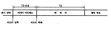
5a는 리드키를 발생한후 제 1 메세지표시시간(이하 "T3시간"이라 칭함) 이내에 리드키의 입력을 해제한 경우의 표시 형태도로서 상기 리드키를 한번 발생한 경우의 표시 형태가 된다. 이 경우 상기 T3시간 내에 표시할 메세지의 어드레스를 표시하고, 상기 T2시간 동안 해당 어드레스의 메세지를 표시하며, 이후 콜링정보를 표시하게 된다.5a is a display mode diagram when the lead key input is released within the first message display time (hereinafter referred to as "T3 time") after generating the lead key, which is the display form when the lead key is generated once. In this case, an address of a message to be displayed within the T3 time is displayed, a message of the corresponding address is displayed for the T2 time, and then calling information is displayed.
5b는 리드키를 계속 누르고 있는 경우의 메세지 표시 형태도로서 저장하고 있는 메세지들을 오토스캔(auto scan)하는 상태를 표시하고 있다. 이 경우 상기 T3시간 동안에는 최초 메세지의 어드레스를 표시한후 상기 리드키의 눌림이 해제될 때 까지 제 2 메세지표시시간(이하 "T4시간"이라 칭함) 간격으로 마이컴(4)의 내부메모리에 저장하고 있는 메세지를 순차적으로 표시부(8)를 통해 표시하며, 상기 리드키의 눌림이 해제되는 시점에서의 메세지는 상기 T2시간동안 표시하게 된다.5b is a message display form diagram when the lead key is kept pressed, and shows the state of autoscanning the stored messages. In this case, during the T3 time, the address of the first message is displayed and stored in the internal memory of the microcomputer 4 at intervals of the second message display time (hereinafter referred to as "T4 time") until the lead key is released. The message is displayed sequentially through the display unit 8, and the message at the time when the lead key is released is displayed for the T2 time.
제 6 도는 메세지가 수신되고 있지 않는 상태에서 표시부(8)에 표시된 콜링정보 표시도로서, 6a는 배터리 전압이 설정 전압보다 낮을 시 저전압 상태(low battery case)을 경보하기 위한 콜링정보의 형태이며, 6b는 마이컴(4)의 내부 메모리에 저장되어 있는 메세지로서 사일런트모드에서 수신되어 아직 읽혀지지 않은 메모리(Unread message)의 갯수를 표시하는 콜링정보의 형태이고, 6c는 노말모드(normal mode)에서 마이컴(4)의 내부 메모리에 저장되어 있는 메세지 갯수를 표시하는 콜링정보의 형태이며, 6d는 아이들(Idle)상태의 콜링정보 형태이다.FIG. 6 is a call information display diagram displayed on the display unit 8 when no message is being received. FIG. 6a is a form of call information for alarming a low battery case when the battery voltage is lower than the set voltage. 6b is a message stored in the internal memory of the microcomputer 4 in the form of calling information indicating the number of unread messages received in the silent mode and 6c is the microcomputer in the normal mode. It is in the form of calling information indicating the number of messages stored in the internal memory of (4), and 6d is the form of calling information in an idle state.
제 7 도는 메모리어드레스의 표시도로서, 7a는 메세지가 수신되지 않는 상태에서 표시부(8)의 표시 일예도로서, 표시부(8)이 12디지트 이하인 경우이며, 7b는 13디지트 이상인 경우 예이다.FIG. 7 is a display diagram of the memory address, where 7a is an example of display of the display section 8 in the state where no message is received, and the display section 8 is 12 digits or less, and 7b is an example of 13 digits or more.
상술한 제 1 도 - 제 7 도의 구성에 의거 본 발명을 상세히 설명한다.The present invention will be described in detail based on the configuration of FIGS. 1 to 7 described above.
먼저 페이저수신기의 동작과정을 설명한다. 안테나(1)를 통해 FSK로 변조되어 전송된 RF신호를 수신하는 RF수신부(2)는 변조상태의 수신데이타를 증폭 및 주파수 변환한 후 복조하여 출력한다. 여기서 상기 수신되는 메세지는 POCSAG코드의 형태를 갖는다고 가정한다. 상기 RF수신부(2)를 출력하는 복조신호를 수신하는 파형정형부(3)는 복조된 데이타를 여파 및 증폭한 후 디지탈 형태를 갖는 2치화 신호로 정형하여 마이컴(4)로 인가한다.First, the operation of the pager receiver will be described. The
상기 마이컴(4)는 초기 전원이 온되면, 상기 메모리(5)에 저장되어 있는 데이타를 억세스하여 내부의 램에 저장한다. 상기 메모리(5)는 18비트의 자기 어드레스데이타 및 3비트의 프레임데이타가 저장하고 있다. 그러므로 초기화 과정이 수행되면, 상기와 같은 메모리(5)에 저장하고 있는 18비트의 어드레스데이타 및 3비트의 프레임데이타가 상기 마이컴(4) 내부의 램에 저장된다. 이후 상기 마이컴(4)는 상기 내부의 램에 저장되는 프레임데이타를 이용하여 한개의 배치(batch)당 8개의 프레임으로 수신되는 데이타중에서 자기프레임의 정보를 선택하고, 수신된 프레임의 정보중에서 18비트의 어드레스데이타를 저장중인 자기 어드레스 데이타와 비교하여 수신되는 메세지가 자기 메세지인가를 판별한다.When the initial power is turned on, the microcomputer 4 accesses the data stored in the
상기와 같은 마이컴(4)은 원칩마이크로프로세서(one chip Processor)의 구성을 가지며, 산요(SANYO)에서 제작 및 판매하는 "LC5864"를 사용할 수 있다.The microcomputer 4 as described above has a configuration of a one chip processor, and may use "LC5864" manufactured and sold by SANYO.
그리고 상기 메세지 판별 과정에서 수신된 메세지가 자기 고유의 어드레스를 갖는 메세지인 것으로 확인되면, 상기 마이컴(4)은 해당하는 프레임에 어드레스 정보와 함께 수신되는 메세지부호어(Message codeword)를 내부의 램에 저장하는 동시에 경보구동부(alert driver)(6)를 구동하여 자신이 호출되었음을 나타내는 경보음(alert tone)을 발생한다. 그리고 상기 마이컴(4)는 표시부(8)를 제어하여 수신된 메세지를 표시한다.If it is confirmed that the message received in the message determination process is a message having its own address, the microcomputer 4 sends a message codeword (Message codeword) received together with address information in a corresponding frame to the internal RAM. Simultaneously with storing, the alert driver 6 is driven to generate an alert tone indicating that it has been called. The microcomputer 4 then controls the display unit 8 to display the received message.
상기와같은 페이저수신기에서 키입력부(9)는 페이저수신기의 동작을 제어하는 기능을 수행한다. 상기 제 1 도에 도시된 키입력부(9)는 리드키(read key) (91) 및 사일런트키(silent key) (92)로 구성된 것을 도시하고 있다. 여기서 상기 사일런트키(92)는 메세지 수신시에 경보음 구동을 방지하기 위한 키 명령을 발생한다. 그러므로 상기 사일런트키(92)의 눌림이 감지되면, 상기 마이컴(4)는 수신되는 메세지를 내부의 램에 저장하는 동시에 표시부(8)를 통해 표시한다.In the pager receiver as described above, the key input unit 9 performs a function of controlling the operation of the pager receiver. The key input unit 9 shown in FIG. 1 shows a read key 91 and a silent key 92. As shown in FIG. Here, the silent key 92 generates a key command for preventing the driving of the alarm sound upon receiving the message. Therefore, when the depression of the silent key 92 is detected, the microcomputer 4 stores the received message in the internal RAM and displays it on the display unit 8.
이때 상기와 같이 일반모드(normal mode) 또는 사일런트모드(silent mode)에서 자기 메세지의 수신을 감지하면, 상기 마이컴(4)는 제 4 도의 4a에 도시된 바와 같이 먼저 T1주기에서 경보구동부(6)을 제어하여 경보음을 발생하는 동시에 표시부(8)을 제어하여 해당하는 메세지를 수신된 메세지를 표시한다. 이후 상기 T1주기가 종료되면, T2주기에는 상기 경보구동부(6)의 동작을 제어하여 경보음의 송출을 중단시키고 표시부(8)을 제어하여 수신된 메세지는 계속 표시한다. 그리고 상기 T2시간이 지나면 상기 표시부(8)을 제어하여 수신된 메세지의 표시 동작을 중지시키고 제 6 도와 같은 콜링정보를 표시한다.At this time, if the reception of the magnetic message in the normal mode (silent mode) or the silent mode (silent mode) as described above, the microcomputer (4) first alarm driver 6 in the period T1 as shown in 4a of FIG. The control unit 8 generates an alarm sound and simultaneously controls the display unit 8 to display the received message. Then, when the T1 cycle ends, the operation of the alarm driver 6 is stopped in the T2 cycle to stop the transmission of the alarm sound, and the display unit 8 is controlled to continuously display the received message. After the T2 time has elapsed, the display unit 8 is controlled to stop displaying the received message and display calling information as shown in FIG.
이때 현재의 모드가 일반모드인 경우에는 제 6 도의 6c와 같이 마이컴(4)의 내부 램에 저장하고 있는 메세지의 갯수를 표시하며, 모드가 사일런트모드인 경우에는 현재 마이컴(4)의 내부 램에 저장하고 있는 읽혀지지 않은 메세지의 갯수를 마이컴(4)의 내부 램에 저장하고 있는 읽혀지지 않은 메세지의 갯수를 제 6 도의 6b와 같이 표시한다. 그리고 현재 마이컴(4)의 내부 램에 저장하고 있는 메세지가 없는 경우에는6d와 같이 메세지가 없음을 표시하며, 베터리가 설정전압보다 낮으면 6a와 같이 저잔압 상태임을 표시한다.At this time, when the current mode is the normal mode, the number of messages stored in the internal RAM of the microcomputer 4 is displayed as shown in 6c of FIG. 6, and when the mode is the silent mode, the internal RAM of the current microcomputer 4 is displayed. The number of unread messages stored is stored in the internal RAM of the microcomputer 4, and the number of unread messages stored is displayed as shown in FIG. 6B. If there is no message currently stored in the internal RAM of the microcomputer 4, it indicates that there is no message as shown in 6d. If the battery is lower than the set voltage, it indicates a low residual pressure state as shown in 6a.
또한, 상기 리드키(91)은 상기 마이컴(4)가 수신된 메세지를 내부의 램에 저장하고 있는 상태에서 저장하고 있는 메세지를 표시하기 위한 키 명령으로 발생된다. 따라서 상기 리드키(91)의 눌림이 감지되면, 상기 리드키(91)의 눌림 횟수에 따라 상기 마이컴(4)는 상기 내부의 램에 저장하고 있는 메세지를 억게스하여 표시부(8)상에 표시한다.Further, the lead key 91 is generated as a key command for displaying the stored message while the microcomputer 4 stores the received message in the internal RAM. Accordingly, when the lead key 91 is pressed, the microcomputer 4 intensifies the message stored in the internal RAM according to the number of times the lead key 91 is pressed and displays the message on the display unit 8. do.
이때 메세지가 수신되는 상태에서 상기 리드키(91)의 발생이 감지된 경우, 상기 마이컴(4)는 제 4 도의 4b와 같이 상기 리드키(91)의 눌림이 감지되는 시점에서 경보구동부(6)을 제어하여 경보음의 발생을 중지시키며, T2주기 동안 표시부(8)을 제어하여 수신된 메세지를 표시하고, 이후 콜링정보를 표시한다.At this time, if the generation of the lead key 91 is detected in the state that the message is received, the microcomputer 4 is the alarm driver 6 when the pressing of the lead key 91 is detected as shown in FIG. To stop the generation of the alarm sound, and control the display unit 8 during the T2 period to display the received message, and then display the calling information.
그러나 제 6 도와 같은 콜링정보를 상기 표시부(8) 상에 표시하고 있는 상태에서 상기 리드키(91)의 발생을 감지하는 경우, 상기 마이컴(4)는 상기 리드키(91)의 눌림 횟수에 따라 메세지의 표시동작을 수행하는데, 한번 눌려진 경우에는 제 5 도의 5a와 같이 표시부(8)상에 내부 램에 저장하고 있는 메세지를 리드하여 표시하고, 상기 리드키(91)이 계속 눌려지는 경우에는 제 5 도의 5b와 같이 마이컴(4)의 내부 램에 저장하고 있는 메세지를 순차적으로 리드하여 표시부(8)상에 표시한다.However, when detecting the occurrence of the lead key 91 while displaying the calling information such as the sixth degree on the display unit 8, the microcomputer 4 according to the number of times the lead key 91 is pressed. When the message is pressed once, the message stored in the internal RAM is read and displayed on the display unit 8 as shown in FIG. 5A, and when the lead key 91 is pressed, the message is displayed. As shown in FIG. 5B, messages stored in the internal RAM of the microcomputer 4 are sequentially read and displayed on the display unit 8.
또한 상태표시부(10)는 마이컴(4)에 제어하에 페이저수신기의 각종 상태를 나타내는데, 램프(102)는 표시부(8)에서 메세지를 표시하는 동안 구동되어 야간과 같이 메세지의 판독이 어려울 경우에도 메세지 표시를 명확하게 하여 주며, 콜링정보 주기에는 "오프"상태를 유지한다. LED(103)은 메세지 수신시 구동되어 시각적으로 경보 상태를 표시하는데, 일반모드(normal mode) 및 사일런트모드에서 모구 구동된다. 또한 모터(M)는 사일렁트모드에서 메세지 수신시 페이저수신기를 진동시켜 사용자가 이를 인지하도록 하는 기능을 수행한다.In addition, the
상기와 같은 본 발명의 페이저수신기에서 메세지 수신시의 동작과정을 제 2 도를 참조하여 살펴보면, 먼저 상기 마이컴(4)은 파형정형부(3)를 통해 수신되는 프레임정보를 수신하여 자기 데이타인가를 검사한다. 이때 수신된 메세지의 어드레스데이타가 자기 고유의 어드레스데이타와 동일한 경우, 상기 마이컴(4)는 (A1) 단계에서 자기 메세지로 인지한다. 상기 (A1)단계에서 자기메세지의 수신을 감지하면, 상기 마이컴(4)는 (A2)단계에서 수신된 메세지를 마이컴(4)의 내부 메모리에 저장하고, (A3)단계에서 경보신호를 송출하여 자신이 호출되었음을 경보한다. 이때 상기 마이컴(4)는 현재의 모드가 일반모드이면 경보구동부(6)를 제어하여 스피커(7)를 통해 메세지가 수신됐음을 알리는 경보음(alert tone)을 발생하며, 사일런트모드이면 상기 모터(104)를 구동하여 진동신호를 발생한다. 그리고 상기 마이컴(4)는 (A4)단계에서 표시부(8)를 제어하여 수신된 메세지를 표시한다.Referring to FIG. 2, the operation process at the time of receiving a message in the pager receiver of the present invention as described above, first, the microcomputer 4 receives the frame information received through the
상기와 같이 경보신호를 송출한 후, 상기 마이컴(4)는 (A5)단계에서 내부 카운터를 동작시켜 T1시간을 카운트 시작하는데, 상기 T1은 스피커(7)을 통해 경보음을 발생하는 동시에 표시부(8)를 통해 수신된 메세지를 표시하는 시간을 의미하는 것으로, 본 발명의 페이저수신기에서는 "8초"주기를 갖는다.After transmitting the alarm signal as described above, the microcomputer 4 starts the counting time T1 by operating the internal counter in step (A5). The T1 generates an alarm sound through the speaker 7 and at the same time displays the display unit ( It means the time for displaying the message received through 8), the pager receiver of the present invention has a "8 seconds" period.
이후 (A6)단계로 진행하여 상기와 같이 T1시간을 카운트하는 제 1 카운트 주기에서 마이컴(4)는 T1시간이 지났는가 검사하며, T1시간 이내일시에는 (A7)단계로 진행하여 리드키(91)의 신호가 발생되었는가를 검사한다. 이때 상기 리드키(91)의 신호 발생시 감지되지 않는 경우, 상기 마이컴(4)는 (A6)단계로 되돌아가 T1시간이 종료될 때 까지 경보음을 발생하는 동시에 표시부(8) 상에는 수신된 메세지를 표시한다. 따라서 자기 메세지가 수신된 후 리드키(91)가 눌려지지 않는 경우에는 제 4 도의 4a와 같이 T1시간 동안 경보음 및 수신된 메세지의 표시동작을 동시에 수행한다.After that, the microcomputer 4 checks whether the T1 time has elapsed in the first count period in which the T1 time is counted as described above (A6). Check if the signal is generated. At this time, if it is not detected when the signal of the lead key 91 is generated, the microcomputer 4 returns to step (A6) and generates an alarm sound until the end of the T1 time, and at the same time receives the received message on the display unit (8). Display. Therefore, when the lead key 91 is not pressed after the self message is received, the alarm sound and the display operation of the received message are simultaneously performed for a time T1 as shown in FIG. 4A.
상기와 같이 경보음 및 메세지 표시 동작을 수행하는 상태에서 T1시간이 경과되면, 상기 마이컴(4)는 (A6)단계에서 이를 인지하고 경보구동부(6)을 제어하여 경보음의 발생을 중지시키고, 표시부(8)을 통해서는 수신된 메세지를 계속 표시할 수 있도록 제어한다. 따라서 상기 메세지가 수신되면 T1시간 동안 메세지의 수신을 알리기 위하여 경보음을 발생하는 동시에 표시부(8) 상에 수신된 메세지를 표시하는 동작을 수행하게 된다. 이후 상기 마이컴(4)는 (A9)단계에서 다시 카운터를 동작시켜 T2시간을 카운트하기 시작한다. 상기 T2시간을 카운트하는 제 2 카운트주기에는 상기한 바와 같이 경보음의 발생이 중단된 상태에서 수신된 메세지를 표시하는 동작을 수행한다. 이때 상기 T2시간의 주기가 다 되면 상기 마이컴(4)는 (A10)단계에서 이를 인지하고, (A11)단계에서 상기 표시부(8)을 제어하여 메세지의 표시동작을 중단시키고, (A12)단계에서 제 6 도와 같은 콜링정보 중에서 해당하는 상태에 따른 콜링정보를 표시한다.When the T1 time has elapsed in the state of performing the alarm sound and message display operation as described above, the microcomputer 4 recognizes this in step (A6) and controls the alarm driver 6 to stop the generation of the alarm sound. The display unit 8 controls the display of the received message. Accordingly, when the message is received, an alarm sound is generated to notify the reception of the message for a time T1, and an operation of displaying the received message on the display unit 8 is performed. Thereafter, the microcomputer 4 starts to count T2 hours by operating the counter again in step (A9). In the second count period for counting the T2 time, as described above, an operation of displaying a received message while the generation of the alarm sound is stopped is performed. At this time, when the period of the T2 time runs out, the microcomputer 4 recognizes this at step A10, and at step A11, stops the display operation of the message by controlling the display unit 8 and at step A12. Calling information according to the corresponding state is displayed among the calling information as shown in FIG.
이때 상기와 같은 동작은 일반모드에서의 동작이 되며, 사일런트모드에서는 상기 경보음 대신에 상기 모터(104)를 구동하여 페이저수신기를 진동시킨다. 이때 상기 마이컴(4)는 사일런트모드에서 수신된 메세지는 언리드메세지(unread message)로 등록한다.At this time, the operation as described above is the operation in the normal mode, in the silent mode to drive the motor 104 instead of the alarm sound to vibrate the pager receiver. At this time, the microcomputer 4 registers the message received in the silent mode as an unread message.
상기와 같이 자기 메세지가 수신되는 상태에서 리드키(91)가 눌려지지 않은 경우에는 제 4 도의 4a와 같이 수행된다. 따라서 먼저 T1시간 동안에는 경보신호(alert tone or vibration)와 함께 수신된 메세지를 표시하고, 뒤이어지는 T2시간 동안에는 경보신호를 중단시키고 수신된 메세지만 표시하며, 이후의 시간에서는 콜링정보를 표시한다. 이때 표시되는 콜링정보는 상기 페이저수신기의 상태에 따라 표시된다. 먼저 현재의 모드가 일반모드인 경우6c와 같이 마이컴(4)의 내부 램에 저장하고 있는 메세지의 갯수를 표시하며, 모드가 사일런트모드인 경우에는 제 6 도의 6b와 같이 읽혀지지 않고 현재 마이컴(4)의 내부 램에 저장하고 있는 메세지의 갯수를 표시한다. 그리고 현재 마이컴(4)의 내부 램에 저장하고 있는 메세지가 없는 경우에는 6d와 같이 메세지가 없음을 표시하며, 배터리가 설정전압보다 낮으면6a와 같이 저전압상태임을 표시한다.As described above, when the lead key 91 is not pressed while the magnetic message is received, the process is performed as shown in FIG. 4A. Therefore, first, a message received together with an alert tone or vibration is displayed for T1 time, an alarm signal is interrupted for a subsequent T2 time, and only the received message is displayed, and the calling information is displayed at a later time. The calling information displayed at this time is displayed according to the state of the pager receiver. First, if the current mode is the normal mode, the number of messages stored in the internal RAM of the microcomputer 4 is displayed as in 6c. If the mode is the silent mode, the current microcomputer 4 is not read as shown in 6b of FIG. Shows the number of messages stored in the internal RAM. If there is no message currently stored in the internal RAM of the microcomputer 4, there is no message as shown in 6d. If the battery is lower than the set voltage, it indicates a low voltage state as shown in 6a.
그러나 메세지가 수신되어 경보신호와 함께 수신된 메세지가 표시되고 있는 상태에서 리드키(91)가 눌려지면, 상기 마이컴(4)는 (A7)단계에서 이를 인지한다. 그러면 상기 마이컴(4)는 (A8)단계에서 상기 경보 신호의 송출을 중지시키고, 표시부(8)을 통해서는 수신된 메세지를 계속 표시할 수 있도록 제어한다. 따라서 제 4 도의 4b와 같이 송출되던 경보신호는 상기 리드키(91)의 입력이 감지되는 시점에서 중단된다. 그리고 상기 마이컴(4)는 (A9)단계에서 다시 카운터를 동작시켜 T2시간을 카운트하기 시작한다. 상기 T2시간을 카운트하는 제 2 카운트주기에서는 상기한 바와 같이 경보신호의 발생이 중단된 상태에서 수신된 메세지를 표시하는 동작을 수행한다. 이때 상기 T2시간의 주기가 다 되면 상기 마이컴(4)는 (A10)단계에서 이를 인지하고, (A11)단계에서 상기 표시부(8)을 제어하여 메세지의 표시동작을 중단시키고, (A12)단계에서 제 6 도와 같은 콜링정보 중에서 해당하는 상태에 따른 콜링정보를 표시한다.However, if the lead key 91 is pressed while the message is received and the message received together with the alarm signal is displayed, the microcomputer 4 recognizes this in step A7. Then, the microcomputer 4 stops transmitting the alarm signal in step (A8) and controls the display unit 8 to continue displaying the received message. Accordingly, the alarm signal transmitted as shown in FIG. 4B is stopped when the input of the lead key 91 is detected. Then, the microcomputer 4 starts to count T2 time by operating the counter again in step (A9). In the second count period for counting the T2 time, as described above, an operation for displaying a received message is performed while the generation of the alarm signal is stopped. At this time, when the period of the T2 time runs out, the microcomputer 4 recognizes this at step A10, and at step A11, stops the display operation of the message by controlling the display unit 8 and at step A12. Calling information according to the corresponding state is displayed among the calling information as shown in FIG.
따라서 상기와 같이 메세지가 수신되어 경보신호가 발생되고 있는 상태에서 리드키(91)이 눌려지면, 상기 마이컴(4)는 제 4 도의 4a와 같이 리드키(91)이 발생되는 시점에서 경보신호(alert tone or vibration)의 발생을 중단하고, 뒤이어지는 T2시간 동안 수신된 메세지만 표시한다. 그리고 상기 T2시간이 경과하면 이후의 시간에서는 제 6 도와 같은 콜링정보들 중에서 해당하는 콜링정보를 표시한다.Accordingly, when the lead key 91 is pressed while the message is received and the alarm signal is generated as described above, the microcomputer 4 generates the alarm signal (at the time when the lead key 91 is generated as shown in FIG. 4A). Stop generating alert tone or vibration and display only messages received during the subsequent T2 hours. After the T2 time has elapsed, corresponding call information is displayed among the calling information as shown in FIG. 6 at a later time.
제 3 도는 리드키(91)에 의해 상기 마이컴(4)의 내부 램에 저장하고 있는 메세지를 리드하여 표시하는 과정을 도시하고 있다. 먼저 상기 리드키(91)가 눌려지면, 상기 마이컴(4)는 (B1)단계에서 리드키(91)의 발생을 인지하고, (B2)단계에서 현재 경보신호가 출력되는 상태인가를 검사한다. 이때 경보신호가 발생되고 있는 상태이면, 메세지가 수신된 상태이므로 (B3)단계에서 제 4 도의 4B와 같이 경보음을 단절하고 리턴한다.3 shows a process of reading and displaying a message stored in the internal RAM of the microcomputer 4 by the
그러나 상기 B2)단계에서 경보신호가 발생되고 있는 상태가 아니면, 제 6 도와 같은 콜링정보를 표시하고 있는 대기상태가 된다. 상기와 같은 대기상태에서 상기 리드키(91)이 발생된 경우, 상기 마이컴(4)는 (B4)단계에서 내부 램의 상태를 검사하여 저장하고 있는 메세지유무를 확인한다. 이때 상기 제 6 도의 6d와 같은 아이들 콜링정보를 표시하는 경우에는 상기 마이컴(4)의 내부 램에 저장된 메세지가 없는 상태가 되며, 이런 경우에는 수신된 리드키(91)의 입력을 무시하고 리턴한다.However, if the alarm signal is not generated in the step B2), the standby state is displayed with the same calling information as the sixth degree. When the lead key 91 is generated in the standby state as described above, the microcomputer 4 checks the state of the internal RAM in step (B4) and checks whether there is a stored message. In this case, when the idle calling information shown in FIG. 6D is displayed, there is no message stored in the internal RAM of the microcomputer 4. In this case, the received input of the lead key 91 is ignored and returned. .
이때 상기 (B4)단계에서 내부의 램에 저장하고 있는 메세지가 있으면, 상기 마이컴(4)는 (B5)단계에서 먼저 메모리 어드레스를 리드하여 제 7 도와 같이 표시하고, (B6)단계에서 T3시간을 카운트한다. 상기 T3시간은 1개의 메세지를 표시할 수 있는 최대 키입력 시간으로 약 2 초가 되며, 이 시간이 넘는 경우에는 다음 어드레스의 메세지가 자동으로 표시되게 된다.At this time, if there is a message stored in the internal RAM in step (B4), the microcomputer (4) first reads the memory address in step (B5) and displays it as shown in the seventh degree, and in step (B6) T3 time Count. The T3 time is the maximum key input time that can display one message, and is about 2 seconds. When this time is exceeded, the message of the next address is automatically displayed.
따라서 제 5 도의 5a와 같이 T3시간 이내에는 표시하고자 하는 메세지의 어드레스가 표시됨을 알 수 있다. 상기 T3시간의 제 3 카운트 동작을 시작한 후 (B7)단계에 T3시간내에 리드키(91)신호가 해제되었는가 검사한다. 이때 상기 T3시간 이내에 상기 리드키(91)의 눌림이 해제되는 경우에는 (B8)단계에서 5a와 같이 T3주기내에 표시부(8)상에 표시된 어드레스의 메세지를 T2주기동안 표시한다. 이는 콜링정보가 표시되는 상태에서 리드키(91)이 한번만 발생된 경우로서, 이러한 경우에는 제 5 도의 5a와 같이 먼저 현재 표시하여야 한 메세지의 어드레스를 표시한 후, T2시간 동안 해당 어드레스에 대응하는 메세지를 표시하고 리턴하여 콜링정보를 표시한다.Therefore, as shown in FIG. 5A, it can be seen that the address of the message to be displayed is displayed within the time T3. After starting the third counting operation of T3 time, it is checked in step (B7) whether the read key 91 signal is released within T3 time. At this time, when the lead key 91 is released within the T3 time period, the message of the address displayed on the display unit 8 is displayed for the T2 period within the T3 period as in step 5a in step (B8). This is a case where the lead key 91 is generated only once while the calling information is displayed. In this case, as shown in FIG. 5A of FIG. Display and return a message to display calling information.
그러나 상기 (B9)단계에서 리드키(91)의 발생이 T3주기를 초과하면, 상기 마이컴(4)는 리드키(91)이 연속적으로 발생하는 것으로 인지한다. 그러면 상기 마이컴(4)는 (B10)단계에서 5B와 같이 T3주기동안 전상태에서 표시하고 있던 어드레스의 메세지를 표시하고, (B11)단계에서 T4시간을 카운트를 시작한다. 여기서 T4는 리드키(91)를 누르고 있는 상태에서 1개의 메세지를 표시하는 시간을 의미한다. 상기와 같이 T4시간의 제 4 카운트가 개시한 후, 상기 마이컴(4)는 (B12)단계에서 리드키(91)의 눌림이 해제되었는가 검사한다. 이때 상기 리드키(91)의 눌림이 계속되고 있는 상태이면, 상기 마이컴(4)는 (B13)단계에서 T4시간의 카운트가 종료되었는가 검사한다. 이때 상기 T4시간의 카운트가 종료되지 않은 상태이면, 상기 마이컴(4)는 표시부(8)를 통해 표시중인 메세지를 변경하지 않고 계속 표시한다.However, if the generation of the lead key 91 exceeds the period T3 in step (B9), the microcomputer 4 recognizes that the lead key 91 is continuously generated. Then, the microcomputer 4 displays the message of the address displayed in the previous state for the period T3 as in step 5B in step (B10), and starts counting T4 time in step (B11). Here, T4 means the time for displaying one message while the lead key 91 is being pressed. After the start of the fourth count of T4 time as described above, the microcomputer 4 checks whether the pressing of the lead key 91 is released in step (B12). If the lead key 91 is being pressed at this time, the microcomputer 4 checks whether the count of T4 time has ended in step (B13). At this time, if the count of the T4 time is not finished, the microcomputer 4 continues to display the message displayed on the display unit 8 without changing it.
그러나 상기(B13)단계에서 T4시간의 카운트를 종료하면, 상기 마이컴(4)는 (B14)단계에서 마이컴(4)의 내부 램에 저장하고 있는 모든 메세지를 표시하였는가 검사한다. 그러나 표시하여야할 메세지가 남아있는 경우, 상기 마이컴(4)는 (B15)단계에서 내부의 램에 현재 표시한 다음 어드레스의 메세지를 리드하여 표시부(8)상에 표시하고, 상기 (B11)단계로 다시 되돌아간다. 즉, 상기 리드키(91)를 누르고 있는 상태에서는 제 5 도의 5b와 같이 메모리에 저장하고 있는 메세지를 순차적인 어드레스에 따라 T4시간 단위로 표시부(8)를 통해 표시한다.However, when the count of T4 time is finished in step (B13), the microcomputer 4 checks whether all messages stored in the internal RAM of the microcomputer 4 are displayed in step (B14). However, if the message to be displayed remains, the microcomputer 4 reads the message of the next address currently displayed in the internal RAM in step (B15) and displays the message on the display unit 8, and proceeds to step (B11). Go back. That is, in the state where the lead key 91 is pressed, the message stored in the memory is displayed on the display unit 8 in units of T4 hours according to the sequential address as shown in FIG. 5B.
이때 상기 (B12)단계에서 임의 시간에 상기 5b와 같이 리드키(91)의 눌림이 해제되면, 해제시의 메세지를 T2시간동안 표시부(8)상에 표시한 후 리턴하여 콜링정보를 표시한다. 또한 상기 (B14)단계에서 리드키(91)신호가 발생하고 있는 상태일시 메모리에 저장하고 있는 모든 메세지를 표시한 경우가 발생되면 (B16)단계로 진행하여 표시부(8)단계에서 메모리의 첫번째 어드레스를 세트한후 상기 (B17)단계로 되돌아간다.At this time, if the lead key 91 is released as shown in 5b at any time in step (B12), the message upon release is displayed on the display unit 8 for T2 time and then returned to display the calling information. In addition, when the case where all the messages stored in the memory are displayed when the lead key 91 signal is generated in step (B14) occurs, the process proceeds to step (B16). In step 8, the first address of the memory is displayed. After setting, return to step (B17).
상기와 같이 작은 규격의 표시부 패널(Small Size display Pannel)을 갖는 페이저수신기 등과 같은 표시장치에서, 메모리 어드레스 인디케이터를 없애고 표시부 상에 메시지 및 콜링정보를 효율적으로 표시할 수 있으며, 리드키 동작에 의한 메모리의 데이타 표시 및 오토 스캔을 수행할 수 있음으로서 메세지 표시를 간편하게 수행할 수 있는 이점이 있다.In a display device such as a pager receiver having a small size display panel as described above, the memory address indicator can be eliminated and the message and the calling information can be efficiently displayed on the display. Since data display and auto scan can be performed, there is an advantage that the message display can be easily performed.
Claims (9)
Priority Applications (2)
| Application Number | Priority Date | Filing Date | Title |
|---|---|---|---|
| KR1019880012637A KR930002752B1 (en) | 1988-09-29 | 1988-09-29 | How to display the message on the pager receiver |
| US07/357,993 US5436619A (en) | 1988-09-29 | 1989-05-30 | Method of displaying message and state in a paging receiver |
Applications Claiming Priority (1)
| Application Number | Priority Date | Filing Date | Title |
|---|---|---|---|
| KR1019880012637A KR930002752B1 (en) | 1988-09-29 | 1988-09-29 | How to display the message on the pager receiver |
Publications (2)
| Publication Number | Publication Date |
|---|---|
| KR900005711A KR900005711A (en) | 1990-04-14 |
| KR930002752B1 true KR930002752B1 (en) | 1993-04-09 |
Family
ID=19278099
Family Applications (1)
| Application Number | Title | Priority Date | Filing Date |
|---|---|---|---|
| KR1019880012637A Expired - Fee Related KR930002752B1 (en) | 1988-09-29 | 1988-09-29 | How to display the message on the pager receiver |
Country Status (2)
| Country | Link |
|---|---|
| US (1) | US5436619A (en) |
| KR (1) | KR930002752B1 (en) |
Families Citing this family (10)
| Publication number | Priority date | Publication date | Assignee | Title |
|---|---|---|---|---|
| JP3100826B2 (en) * | 1994-03-17 | 2000-10-23 | シャープ株式会社 | Pager with message display |
| JP2786166B2 (en) * | 1996-06-21 | 1998-08-13 | 静岡日本電気株式会社 | Radio selective call receiver |
| JP2990081B2 (en) * | 1996-12-26 | 1999-12-13 | 静岡日本電気株式会社 | Wireless selective call receiving system and wireless selective call receiving method |
| JP4401448B2 (en) * | 1997-02-24 | 2010-01-20 | 株式会社半導体エネルギー研究所 | Method for manufacturing semiconductor device |
| US6504580B1 (en) * | 1997-03-24 | 2003-01-07 | Evolve Products, Inc. | Non-Telephonic, non-remote controller, wireless information presentation device with advertising display |
| JP3012598B2 (en) * | 1998-06-29 | 2000-02-21 | 静岡日本電気株式会社 | Radio selective call receiver with display and message information display method |
| KR20030072147A (en) * | 2002-03-05 | 2003-09-13 | 한국델파이주식회사 | Non pressure sensitive droop fitting type flow control valve for hydraulic pump of power steering system |
| US8112481B2 (en) * | 2003-03-28 | 2012-02-07 | Microsoft Corporation | Document message state management engine |
| US7614057B2 (en) * | 2003-03-28 | 2009-11-03 | Microsoft Corporation | Entity linking system |
| US8185594B2 (en) | 2008-06-13 | 2012-05-22 | Seiko Epson Corporation | Real-time messaging system for an image display device |
Family Cites Families (8)
| Publication number | Priority date | Publication date | Assignee | Title |
|---|---|---|---|---|
| US4419668A (en) * | 1981-09-25 | 1983-12-06 | Motorola, Inc. | Combined tone only and tone voice multiple alert pager |
| JPS58131831A (en) * | 1982-02-01 | 1983-08-05 | Nec Corp | Radio selection and calling receiver |
| GB2118337B (en) * | 1982-02-09 | 1986-01-15 | Nippon Electric Co | Pager receiver for giving at least one of extraordinary tones and extraordinary displays |
| JPS58138136A (en) * | 1982-02-12 | 1983-08-16 | Nec Corp | Inter-call receiver with display |
| JPS58178642A (en) * | 1982-04-13 | 1983-10-19 | Nec Corp | Individual selection and calling receiver with display |
| JPS61176218A (en) * | 1985-01-31 | 1986-08-07 | Nippon Telegr & Teleph Corp <Ntt> | Selective call receiver |
| US4821021A (en) * | 1987-01-13 | 1989-04-11 | Nec Corporation | Selective calling radio display pager having a message recalling algorithm which simplifies operations |
| CA1298620C (en) * | 1987-06-30 | 1992-04-07 | Walter Lee Davis | Prioritization of stored messages in a digital voice paging receiver |
-
1988
- 1988-09-29 KR KR1019880012637A patent/KR930002752B1/en not_active Expired - Fee Related
-
1989
- 1989-05-30 US US07/357,993 patent/US5436619A/en not_active Expired - Lifetime
Also Published As
| Publication number | Publication date |
|---|---|
| KR900005711A (en) | 1990-04-14 |
| US5436619A (en) | 1995-07-25 |
Similar Documents
| Publication | Publication Date | Title |
|---|---|---|
| US4385295A (en) | Pager with visible display indicating unread messages | |
| KR930002752B1 (en) | How to display the message on the pager receiver | |
| KR20010023703A (en) | Method and apparatus for displaying a message which has been received | |
| KR960012958B1 (en) | Paging receiver and received signal control circuit | |
| JP2968705B2 (en) | Radio selective call receiver | |
| KR960014493B1 (en) | Microcomputer controlled display backlight | |
| JPH0642647B2 (en) | Selective call receiver capable of receiving message information | |
| KR19980013929A (en) | Location notification and contact notification method when lost pager receiver | |
| EP0499247A1 (en) | Radio pager with power-backup memory for storing uncompleted messages | |
| US5896096A (en) | Paging receiver and a sequential vibrating method therefor | |
| JPH06177817A (en) | Wireless selective call receiver | |
| US6052564A (en) | Portable individual calling device | |
| US6124801A (en) | Radio selective calling receiver and calling method | |
| KR930002751B1 (en) | Apparatus for displaying self address data in paging receiver | |
| KR100229879B1 (en) | Method and apparatus for generating alert in radio paging receiver | |
| JPH0325972B2 (en) | ||
| GB2308709A (en) | Selective calling radio receiver | |
| JP2666635B2 (en) | Individually selected call receiver with display | |
| JP2821337B2 (en) | Radio selective call receiver | |
| JP2890929B2 (en) | Radio selective call receiver | |
| JPH03277025A (en) | Display pager | |
| JPH0750863A (en) | Paging receiver | |
| RU2127947C1 (en) | Method for urgent transmission of response message in duplex pager | |
| KR910007653B1 (en) | How to display the address code on the pager receiver | |
| JPH11275183A (en) | Portable terminal |
Legal Events
| Date | Code | Title | Description |
|---|---|---|---|
| PA0109 | Patent application |
St.27 status event code: A-0-1-A10-A12-nap-PA0109 |
|
| R17-X000 | Change to representative recorded |
St.27 status event code: A-3-3-R10-R17-oth-X000 |
|
| PG1501 | Laying open of application |
St.27 status event code: A-1-1-Q10-Q12-nap-PG1501 |
|
| A201 | Request for examination | ||
| PA0201 | Request for examination |
St.27 status event code: A-1-2-D10-D11-exm-PA0201 |
|
| E902 | Notification of reason for refusal | ||
| PE0902 | Notice of grounds for rejection |
St.27 status event code: A-1-2-D10-D21-exm-PE0902 |
|
| T11-X000 | Administrative time limit extension requested |
St.27 status event code: U-3-3-T10-T11-oth-X000 |
|
| T11-X000 | Administrative time limit extension requested |
St.27 status event code: U-3-3-T10-T11-oth-X000 |
|
| T11-X000 | Administrative time limit extension requested |
St.27 status event code: U-3-3-T10-T11-oth-X000 |
|
| P11-X000 | Amendment of application requested |
St.27 status event code: A-2-2-P10-P11-nap-X000 |
|
| P13-X000 | Application amended |
St.27 status event code: A-2-2-P10-P13-nap-X000 |
|
| G160 | Decision to publish patent application | ||
| PG1605 | Publication of application before grant of patent |
St.27 status event code: A-2-2-Q10-Q13-nap-PG1605 |
|
| E701 | Decision to grant or registration of patent right | ||
| PE0701 | Decision of registration |
St.27 status event code: A-1-2-D10-D22-exm-PE0701 |
|
| GRNT | Written decision to grant | ||
| PR0701 | Registration of establishment |
St.27 status event code: A-2-4-F10-F11-exm-PR0701 |
|
| PR1002 | Payment of registration fee |
St.27 status event code: A-2-2-U10-U11-oth-PR1002 Fee payment year number: 1 |
|
| PR1001 | Payment of annual fee |
St.27 status event code: A-4-4-U10-U11-oth-PR1001 Fee payment year number: 4 |
|
| PR1001 | Payment of annual fee |
St.27 status event code: A-4-4-U10-U11-oth-PR1001 Fee payment year number: 5 |
|
| PR1001 | Payment of annual fee |
St.27 status event code: A-4-4-U10-U11-oth-PR1001 Fee payment year number: 6 |
|
| PR1001 | Payment of annual fee |
St.27 status event code: A-4-4-U10-U11-oth-PR1001 Fee payment year number: 7 |
|
| PR1001 | Payment of annual fee |
St.27 status event code: A-4-4-U10-U11-oth-PR1001 Fee payment year number: 8 |
|
| PR1001 | Payment of annual fee |
St.27 status event code: A-4-4-U10-U11-oth-PR1001 Fee payment year number: 9 |
|
| PR1001 | Payment of annual fee |
St.27 status event code: A-4-4-U10-U11-oth-PR1001 Fee payment year number: 10 |
|
| PR1001 | Payment of annual fee |
St.27 status event code: A-4-4-U10-U11-oth-PR1001 Fee payment year number: 11 |
|
| PR1001 | Payment of annual fee |
St.27 status event code: A-4-4-U10-U11-oth-PR1001 Fee payment year number: 12 |
|
| PR1001 | Payment of annual fee |
St.27 status event code: A-4-4-U10-U11-oth-PR1001 Fee payment year number: 13 |
|
| PR1001 | Payment of annual fee |
St.27 status event code: A-4-4-U10-U11-oth-PR1001 Fee payment year number: 14 |
|
| FPAY | Annual fee payment |
Payment date: 20070312 Year of fee payment: 15 |
|
| PR1001 | Payment of annual fee |
St.27 status event code: A-4-4-U10-U11-oth-PR1001 Fee payment year number: 15 |
|
| LAPS | Lapse due to unpaid annual fee | ||
| PC1903 | Unpaid annual fee |
St.27 status event code: A-4-4-U10-U13-oth-PC1903 Not in force date: 20080410 Payment event data comment text: Termination Category : DEFAULT_OF_REGISTRATION_FEE |
|
| PC1903 | Unpaid annual fee |
St.27 status event code: N-4-6-H10-H13-oth-PC1903 Ip right cessation event data comment text: Termination Category : DEFAULT_OF_REGISTRATION_FEE Not in force date: 20080410 |
|
| P22-X000 | Classification modified |
St.27 status event code: A-4-4-P10-P22-nap-X000 |