KR910005062B1 - Insulation cover for insulation and cold insulation of boiler and air conditioner pipe - Google Patents
Insulation cover for insulation and cold insulation of boiler and air conditioner pipe Download PDFInfo
- Publication number
- KR910005062B1 KR910005062B1 KR1019880017172A KR880017172A KR910005062B1 KR 910005062 B1 KR910005062 B1 KR 910005062B1 KR 1019880017172 A KR1019880017172 A KR 1019880017172A KR 880017172 A KR880017172 A KR 880017172A KR 910005062 B1 KR910005062 B1 KR 910005062B1
- Authority
- KR
- South Korea
- Prior art keywords
- layer
- cover
- insulation
- glass fiber
- pipe
- Prior art date
- Legal status (The legal status is an assumption and is not a legal conclusion. Google has not performed a legal analysis and makes no representation as to the accuracy of the status listed.)
- Expired
Links
Images


Classifications
-
- F—MECHANICAL ENGINEERING; LIGHTING; HEATING; WEAPONS; BLASTING
- F16—ENGINEERING ELEMENTS AND UNITS; GENERAL MEASURES FOR PRODUCING AND MAINTAINING EFFECTIVE FUNCTIONING OF MACHINES OR INSTALLATIONS; THERMAL INSULATION IN GENERAL
- F16L—PIPES; JOINTS OR FITTINGS FOR PIPES; SUPPORTS FOR PIPES, CABLES OR PROTECTIVE TUBING; MEANS FOR THERMAL INSULATION IN GENERAL
- F16L59/00—Thermal insulation in general
- F16L59/02—Shape or form of insulating materials, with or without coverings integral with the insulating materials
-
- F—MECHANICAL ENGINEERING; LIGHTING; HEATING; WEAPONS; BLASTING
- F16—ENGINEERING ELEMENTS AND UNITS; GENERAL MEASURES FOR PRODUCING AND MAINTAINING EFFECTIVE FUNCTIONING OF MACHINES OR INSTALLATIONS; THERMAL INSULATION IN GENERAL
- F16L—PIPES; JOINTS OR FITTINGS FOR PIPES; SUPPORTS FOR PIPES, CABLES OR PROTECTIVE TUBING; MEANS FOR THERMAL INSULATION IN GENERAL
- F16L51/00—Expansion-compensation arrangements for pipe-lines
Landscapes
- Engineering & Computer Science (AREA)
- General Engineering & Computer Science (AREA)
- Mechanical Engineering (AREA)
- Thermal Insulation (AREA)
Abstract
내용 없음.No content.
Description
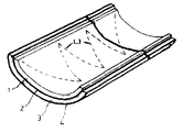
제1도는 단열카바의 단면구조와 절단된 접착면을 도시한 사시도.1 is a perspective view showing a cross-sectional structure and the cut adhesive surface of the insulating cover.
제2도는 본 발명의 단열카바를 파이프에 설치한후의 단면을 나타내는 단면도이다. 제2a도는 단열카바의 접착면이 요철홈을 이루는 것을 도시한 것이고, 제2b도는 단열카바의 접착면이 상하 돌출부를 이루는 것을 도시한 것이다.2 is a cross-sectional view showing a cross section after the heat insulating cover of the present invention is installed in a pipe. FIG. 2a illustrates that the adhesive surface of the insulating cover forms an uneven groove, and FIG. 2b illustrates that the adhesive surface of the insulating cover forms an upper and lower protrusion.
제3도는 본 발명의 단열카바를 제조할 때 유리섬유층 또는 발포우레탄층을 접착하는 방법을 설명하는 도면이다.3 is a view for explaining a method of adhering a glass fiber layer or a foamed urethane layer when producing the insulating cover of the present invention.
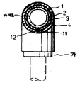
제4도는 본 발명의 한 구체예인 엘보우형 파이프에 설치된 단열카바를 나타낸 사시도 및 그 단면을 나타낸 도면이다.4 is a perspective view showing a heat insulation cover installed in an elbow pipe which is one embodiment of the present invention, and a cross-sectional view thereof.
제5도는 본 발명의 한 구체예인 T자형 파이프에 설치된 단열카바를 나타낸 사시도 및 그 단면을 나타낸 도면이다.5 is a perspective view showing a heat insulation cover installed on a T-shaped pipe of one embodiment of the present invention and a cross-sectional view thereof.
제6a도는 직선형태의 파이프를 단열하기 위한 카바로서 그 열결부분에서 접착제로 접착시킬 수 있도록 한 단부는 "가"로 도시된 바와 같이 외부에 홈이 형성되며, 다른 단부는 내부에 홈이 형성된 것을 도시한다. 제6b도는 엘보우형의 단열카바로서 외부의 홈이 "가"로 표시된 홈위에 접착되도록 도시된 도면이다.Figure 6a is a cover for insulating a straight pipe, the end of which can be glued to the adhesive portion at the thermally formed grooves on the outside, as shown in Fig. 2, the other end is formed with a groove inside Illustrated. FIG. 6b is an elbow-shaped insulating cover, in which an outer groove is bonded to a groove marked by ".
제7도는 본 발명의 단열카바를 직선형태의 파이프와 엘보우형 파이프에 서로 결합시킨 상태를 도시한 부분 절단면도이다.7 is a partial cutaway view showing a state in which the insulating cover of the present invention is coupled to each other in a straight pipe and an elbow pipe.
* 도면의 주요부분에 대한 부호의 설명* Explanation of symbols for main parts of the drawings
1 : 유리섬유층 또는 발포우레탄층 2, 4 : 알루미늄 박막층1: glass fiber layer or
3 : 발포우레탄층 또는 유리섬유층 11 : 돌출부3: foamed urethane layer or glass fiber layer 11: protrusion
12 : 홈 13 : 상부돌출부12: groove 13: upper projection
14 : 하부돌출부14: lower protrusion
본 발명은 보일러 및 냉방기의 파이프를 보온 또는 보냉하고 외부와의 단열을 위한 파이프의 카바 및 그 제조 방법에 관한 것이다.The present invention relates to a cover of a pipe for insulating or cooling the pipes of a boiler and an air conditioner, and to insulate the outside, and a method of manufacturing the same.
본 발명은 또한 보일러 및 냉방기의 파이프를 효과적으로 보온하고 또는 보냉할 수 있도록 한 단열카바에 관한 것으로 직선형태의 파이프는 물론 직선형태가 아닌 연결부분의 파이프도 완벽하게 단열할 수 있는 카바에 관한 것이다. 즉 본 발명은 보일러 및 냉방기의 직선형태의 파이프는 물론 엘보우형, 유니온, T자형, +자형, 레듀서(reducer), 밸브, 플랜지등 직선형태가 아닌 연결부분의 파이프를 효과적으로 단열하기 위한 카바에 관한 것이다. 나아가서 본 발명은 상기 설명한 단열카바를 제조함에 있어서 단열효과를 높이기 위하여 다수층의 구조를 가지며 그 층사이에는 공기층을 형성하는 단열카바에 관한 것이다.The present invention also relates to a heat insulation cover that can effectively insulate or cool the pipes of the boiler and the air conditioner, and relates to a cover that can insulate the pipe of the connection part which is not straight as well as the straight pipe. That is, the present invention provides a cover for effectively insulating pipes of non-linear connection parts such as elbow type, union type, T type, + type, reducer, valve, flange, as well as straight pipes of boiler and air conditioner. It is about. Furthermore, the present invention relates to a heat insulating cover having a multi-layered structure and forming an air layer therebetween in order to increase the heat insulating effect in manufacturing the heat insulating cover described above.
일반적으로 모든 보일러는 보일러 자체와 그 보일러에 의하여 난방 또는 온수를 필요로 하는 곳까지 여러 가지 형태의 파이프로 연결되어 있고, 건축 구조상 또는 공정설계상등의 여러 가지 이유로 인하여 직선형태의 파이프는 물론 여러 가지 다양한 형태의 연결부분으로 이루어져 있다.In general, all boilers are connected by various types of pipes to the boiler itself and the place where heating or hot water is required by the boiler, and for various reasons such as construction structure or process design, as well as straight pipes, It consists of various types of connections.
하절기에 사용되는 냉방기 또한 냉방이나 냉수를 필요로 하는 곳까지 여러 가지 형태의 파이프로 연결되어 있고, 보일러의 경우와 유사하게 직선형태의 파이프와 이를 연결하는 부분으로 이루어져 있다.The air conditioner used in the summer is also connected to various types of pipes to where cooling or cold water is needed, and is composed of a straight pipe and a part connecting it similarly to a boiler.
이러한 보일러 및 냉방기의 모든 파이프를 보온, 보냉시킴으로서 열효율을 증가시키고 나아가서 에너지를 절약하고자하는 노력은 이 분야에서 꾸준히 행하여져 왔다.Efforts have been made in this field to increase thermal efficiency and further energy saving by keeping all pipes of such boilers and air conditioners cool.
대한민국 특허 공고 번호 제84-2205호 개시된 바와 같은 단열파이프의 발명하에서 이루어졌다.The invention was made under the invention of an insulation pipe as disclosed in Korean Patent Publication No. 84-2205.
또 각종 유체관의 단열판을 구성함에 있어서 합성수지 또는 합성고무판으로 되는 단열판상에 V형 요흠을 갖는 종돌조와 횡돌조를 간설하여 유체관의 주면에 포설시킨 다수의 단열공간이 형성된 파이프용 단열판이 대한민국 실용신안 공고 번호 제83-733호에 기재되어 있다.In addition, in constructing a heat insulating plate of various fluid pipes, a pipe heat insulating plate having a plurality of heat insulating spaces formed on the main surface of a fluid pipe by arranging a bell and cross stone having a V-shaped recess on a heat insulating plate made of synthetic resin or synthetic rubber is installed in Korea. It is described in new model notification number 83-733.
그리고 현재 시판되고 있는 에너지관리공단 승인 경기 제8-1013-1호 제품인 두나론(Dunalon)도 상기 설명한 보일러 및 냉방기의 파이프를 보온 또는 보온시키기 위한 단열카바로는 그 단열효과면에 있어서 충분하지 못한 실정이다.In addition, Dunalon, a commercial product No. 8-1013-1 approved by the Korea Energy Management Corporation, is not sufficient for the insulation effect to insulate or insulate the pipes of the boiler and air conditioner described above. It is true.
본 발명의 발명자는 1988년 대한민국 특허출원 제15436호의 발명을 기초로 본 발명을 개발하기에 이르렀다. 특허출원 제15436호의 단열카바는 엘보우형, T자형등의 직선형태가 아닌 부분을 단열할 수 있도록 한 카바와 이를 연결하기에 편리하고 효율적인 직선형태의 카바를 개선한 발명이다.The inventor of the present invention came to develop the present invention based on the invention of Korean Patent Application No. 15436 in 1988. Insulation cover of Patent Application No. 15436 is an invention that improves the cover that can insulate non-linear parts such as elbow type, T-shape and a straight cover that is convenient and efficient to connect it.
상기의 특허출원 제15436호의 발명이 직선형태가 아닌 연결부분을 적절하게 단열할 수 있도록 개발되었음에도 불구하고, 이는 보다 완벽한 단열효과를 기대할수 없었다.Although the invention of the above-mentioned patent application No. 15436 was developed to properly insulate a connection portion that is not a straight line, it could not be expected a more perfect insulation effect.
왜냐하면 유리섬유층, 발포우레탄층 및 알루미늄 박막층만으로 이루어진 단열카바의 구조는 여전히 상당부분의 열이 외부로 발산되거나 내부로 침투되어 보온 또는 보냉의 효과를 완벽하게 구할수 없었다. 즉, 유리섬유층이나 발포우레탄층은 단일층으로 이루어져 있어서 완벽한 열의 차단효과를 기할수 없기 때문에, 이를 다수층의 유리섬유와 다수층의 우레탄으로 형성시키고 그 유리섬유층과 우레탄층에는 열의 차단효과가 가장 좋은 알루미늄 박막층을 형성시킴으로써 제조된 것이다. 유리섬유층이나 발포우레탄층이 단일층으로 이루어져 있는 경우 보다 다수층의 유리섬유와 다수층의 우레탄으로 이루어진 경우에는 그 층과 층사이에 공기가 포함될 수 있어서 단열효과를 높일 수 있는 것이다. 이러한 미세한 공기층을 형성할 수 있도록 접착하는 방법도 하기에 설명하는 바와 같이 이루어 질수 있다. 또한 본 발명의 상기 구조는 서로 호환성을 나타낼수 있는 것으로, 발포우레탄층과 유리섬유층은 서로 그 위치가 교체될 수 있으며 한 종류의 층 즉 알루미늄 박막층을 사이에 두고 양쪽에 발포우레탄층만으로 또는 유리섬유층만으로 구성될 수 있다. 그러나 어느 경우이든지, 다수층으로 이루어져야 함은 불변의 사실이다. 본 발명은 상기 설명과 같이 단열효과를 더욱 양호하게 하고 나아가서 직선형태의 파이프와 연결부분을 완전히 보온 또는 보냉할수 있도록 고안된 것이다.Because the structure of the insulation cover consisting of only a glass fiber layer, a polyurethane foam layer and an aluminum thin film layer is still a large part of the heat dissipated to the outside or penetrated into the inside was not able to obtain the effect of warming or cooling completely. That is, since the glass fiber layer or the foamed urethane layer is composed of a single layer, it is impossible to achieve a perfect heat shielding effect. Therefore, the glass fiber layer and the urethane layer are formed of a plurality of glass fibers and a plurality of urethane layers. It is produced by forming a good aluminum thin film layer. When the glass fiber layer or the foamed urethane layer is composed of a single layer, when the glass fiber is formed of a plurality of layers and the urethane of a plurality of layers, air may be included between the layers and the layers, thereby increasing the thermal insulation effect. A method of adhering to form such a fine air layer may also be made as described below. In addition, the structure of the present invention can exhibit compatibility with each other, the foamed polyurethane layer and the glass fiber layer can be interchanged with each other, and one type of layer, that is, with only the foamed polyurethane layer on both sides or the glass fiber layer between the aluminum thin film layer between It may consist of only. In either case, however, the fact that it must be made up of multiple layers is an unchanging fact. As described above, the present invention is designed to further improve the thermal insulation effect and further to insulate or cool the pipe and the connecting portion in a straight line shape.
따라서 본 발명의 목적은 보일러 및 냉방기의 파이프를 보온 또는 보냉을 완벽히 행함으로써 전체적인 열효율을 향상 시키고자 하는 것이다. 나아가서 본 발명의 목적은 보일러 및 냉방기의 열효율을 증가시킴으로써 에너지를 절약하고자 하는 것이다. 또 본 발명의 목적은 보온, 보냉용 단열카바의 접착을 용이하게 행할수 있도록 하고 또한 그 접착성을 향상 시킴으로써 작업상의 능률을 가져오는 데에 있다. 본 발명의 목적은 또한 파이프의 직선부분과 엘보우형, T자형등의 연결부분과의 결합부분을 효과적으로 단열하기 위한 것이다. 본 발명의 또 다른 목적은 단열효과를 높이기 위하여 본 발명의 단열카바를 제조하는 방법을 제공하기 위한 것이다. 냉방기 및 보일러의 보냉, 보온을 위한 단열효과를 극대화하기 위하여 본 발명의 단열카바는 파이프와 접촉하는 카바의 내부층을 유리섬유층으로 하고, 그 다음으로 알루미늄 박막층, 그 다음의 외부에는 발포우레탄층으로 하며 카바의 외부를 다시 알루미늄 박막층으로 한 구조를 이룬다. 특히 이 구조중에서 특징으로 되고 있는 것은, 상기의 유리섬유층 및 발포우레탄층이 다수층으로 이루어져 있어서 각 층사이에는 공기가 내포될수 있도록 즉 미세한 공기층을 형성하도록 하여 단열효과를 극대화한다는 점이다. 일한 유리섬유층 및 발포우레탄층의 다수층의 층사이에 공기층을 형성할 수 있도록 하는 제조방법도 본 발명의 또다른 특징이다.Therefore, an object of the present invention is to improve the overall thermal efficiency by performing a heat or cool the pipe of the boiler and air conditioner completely. It is further an object of the present invention to save energy by increasing the thermal efficiency of boilers and air conditioners. In addition, an object of the present invention is to bring about the work efficiency by making it easy to bond the heat-insulating cover for keeping warm and cold, and also improving the adhesion. It is also an object of the present invention to effectively insulate a coupling portion between a straight portion of a pipe and a connecting portion such as an elbow type or a T-shape. Still another object of the present invention is to provide a method of manufacturing the insulation cover of the present invention in order to increase the insulation effect. In order to maximize the thermal insulation effect for cooling and thermal insulation of air conditioners and boilers, the insulating cover of the present invention is made of a glass fiber layer on the inner layer of the cover in contact with the pipe, followed by an aluminum thin film layer, followed by a foamed polyurethane layer on the outside. The outer surface of the cover is made of aluminum thin film layer. In particular, the structure is characterized in that the glass fiber layer and the foamed urethane layer is composed of a plurality of layers to maximize the thermal insulation effect by forming a fine air layer, that is, air can be contained between each layer. Another feature of the present invention is a manufacturing method for forming an air layer between multiple layers of a glass fiber layer and a foamed urethane layer.
또한 본 발명의 단열카바는 파이프와 접촉하는 카바의 내부층을 발포우레탄층으로 하고, 그 다음으로 알루미늄 박막층, 그 다음의 외부에는 유리섬유층으로 하며 카바의 외부를 다시 알루미늄 박막층으로 한 구조를 포함 한다. 나아가서 열의 차단효과가 좋은 알루미늄 박막층을 중간에 두고 그 양쪽에 동일한 층을 형성시키는 구조도 포함한다. 즉, 파이프와 접촉하는 카바의 내부층을 발포우레탄층, 그 다음으로 알루미늄 박막층, 그 다음으로 발포우레탄층, 및 카바의 가장 외부에 알루미늄 박막층의 구조나 또는 유리섬유층, 알루미늄 박막층, 유리섬유층, 및 알루미늄 박막층의 구조를 포함한다.In addition, the insulating cover of the present invention includes a structure in which the inner layer of the cover in contact with the pipe is a polyurethane foam layer, followed by an aluminum thin film layer, followed by a glass fiber layer on the outside, and an outer thin film layer on the outside of the cover. . Furthermore, a structure in which the same thin film layer is formed on both sides with the aluminum thin film layer having a good heat blocking effect in the middle. That is, the inner layer of the cover in contact with the pipe is a foamed urethane layer, followed by an aluminum thin film layer, then a foamed urethane layer, and a structure of an aluminum thin film layer on the outermost side of the cover or a glass fiber layer, an aluminum thin film layer, a glass fiber layer, and It includes the structure of the aluminum thin film layer.
이상에 열거된 본 발명의 어떠한 구체예도 유리섬유층 및 발포우레탄층이 다수층으로 이루어졌다는 점이다. 그럼으로써 각 층사이에는 공기가 내포될 수 있도록 즉 미세한 공기층을 형성하도록 하여 단열효과를 극대화하고자 하는 것이 본 발명의 특징이다.In any of the embodiments of the present invention listed above, the glass fiber layer and the foamed urethane layer consist of a plurality of layers. Thus, it is a feature of the present invention to maximize the thermal insulation effect by allowing air to be contained between each layer, that is, to form a fine air layer.
파이프의 직선부분을 보온, 보냉하는 단열카바는 그 카바의 축방향으로 전달되어 파이프에 설치된 후 접착제에 의하여 접착될수 있도록 접착면을 가지며, 이 접착면의 접착성을 양호하게 하기 위하여 요철홈을 이루거나 또는 상하돌출부를 이루게 하는 것도 본 발명의 특징이다.Insulating cover that insulates and insulates the straight part of the pipe has an adhesive surface to be transferred in the axial direction of the cover to be adhered by adhesive after being installed on the pipe, and to form an uneven groove to improve the adhesiveness of the adhesive surface. Or up and down protrusions are also features of the present invention.
상기 설명한 본 발명의 특징으로써 본 발명의 목적을 적절히 달성하기 위하여 첨부된 도면을 참고로 하기에 상세히 설명한다.Reference to the accompanying drawings in order to properly achieve the object of the present invention as a feature of the present invention described above will be described in detail below.
제1도에 도시된 바와 같이, 본 발명의 한 구체예의 보온, 보냉용 단열카바는 가장 내부에 위치하여 파이프의 외부와 접촉되는 엷은 유리섬유의 다수층으로 이루어진 유리섬유층(1), 유리섬유층(1)의 외부에 단일막으로 이루어진 알루미늄 박막층(2), 그 박막층(2)의 외부에 엷은 발포우레탄의 다수층으로 이루어진 발포우레탄층(3), 및 단열카바의 가장 외부에 단일막으로 이루어진 알루미늄 박막층(4)으로 구성된다. 특히 상기 설명한 단열카바의 구조중에서, 유리섬유층(1)과 발포우레탄층(3)은 각각 여러층의 엷은 유리섬유층과 엷은 발포우레탄층으로 이루어진다. 상기의 유리섬유층 및 발포우레탄층이 다수층 구조를 형성함으로써 각층 사이에는 공기가 내포될 수 있도록 즉 미세한 공기층을 형성하도록 한다. 여기서 다수층을 형성하고 유리섬유층이나 발포우레탄층은 많은 층으로 할수록 그 단열 효과가 좋다. 하지만 유리섬유층이나 우레탄층을 너무 엷게 층으로 절단한다면 찢어지는 현상이 나타나서 작업공정상 매우 불편하다. 보통 3 내지 9까지의 다수층을 형성하도록 하는 것이 바람직하며 4 내지 7정도의 층을 서로 접착제로 접착시키는 것이 더 바람직하다. 각 층사이는 제조 공정상의 편리를 위하여 서로 접착되어야 하고 또 단열카바를 파이프에 설치시킬 때 서로 접착시키지 않음으로써 분리될 수 있는 결점을 해결하기 위하여 서로 접착되어야 한다. 그러나 이들 각 층의 접착은 또한 단열효과를 높이기 위하여 각 층 사이에 공기가 내포될 수 있어야 한다는 점이 반드시 고려되어야 한다. 따라서 상반되는 이 두 조건을 모두 만족시키기 위하여 이들의 층을 서로 접착하는 방법이 제3도에 잘 나타나 있다. 즉 발포우레탄층 또는 유리섬유층의 전면을 접착제로 접착하는 것이 아니고, 설치 작업시에 서로 분리되지 않을 만큼 제3도의 "나"로 표시된 바와 같이, 극히 일부만을 접착제로써 접착시킨다. 반드시 "나"의 점선을 따를 필요가 없는 만큼 단열효과와 접착성을 서로 극대화할 수 있도록 여러가지 변형된 형태의 접착방법이 응용될 수 있지만, 어떠한 접착방법도 본 발명의 기술의 영역에 해당하는 한 본 발명의 범위로부터 벗어나지 아니할 것이다.As shown in FIG. 1, the thermal insulation and thermal insulation cover of one embodiment of the present invention is a glass fiber layer (1) made of a plurality of layers of thin glass fibers located in the innermost and in contact with the outside of the pipe, glass fiber layer ( Aluminum
본 발명의 단열카바는 어느 한 지점에 축방향을 따라 절단되어 파이프 상에 설치된 후 그 절단면을 접착제로 접착시킨다. 이절단되는 접착면은 제2a도와 같이 요철홈(11,12)을 형성하여 접착력과 단열효과를 향상시킬수 있다. 이 절단면을 통해 파이프를 삽입시킨 후 접착제로 접착시킨다. 요철홈(11,12)은 제2a도와 같이 돌출부(11)와 그 돌출부가 삽입되어 접착될수 있도록 한 홈(12)으로 이루어진다. 또 제2a도의 변형형태로서 제2b도에 도시된 상하돌출부(13,14)를 이루는 절단면도 사용된다. 직선형태가 아닌 연결부분을 단열하기 위한 카바도 각각 적절한 지점에서 절단되어 파이프를 감쌀수 있도록 하며, 이들의 단면은 상기에 설명한 제2도와 동일하다.The insulating cover of the present invention is cut along the axial direction at any one point and installed on the pipe, and then the cut surface is bonded with an adhesive. This cut adhesive surface can form the
그리고 단열카바와 절단면을 접착하기 위한 접착제로는 우레탄용 또는 유리섬유용 접착제가 사용되며 거진 화성 유한 회사의 제품인 상표 "뉴본드"의 접착제가 이용 가능하다. 이반적으로 보일러 또는 냉방기의 파이프에 사용되고 있는 크기로는 15ø부터 150ø(단위 mm)까지 아주 다양하다. 본 발명의 단열카바는 파이프의 크기에 맞는 것들을 제작함으로써 어떠한 경우에도 사용될 수 있도록 할 수 있다.As the adhesive for bonding the insulation cover and the cut surface, an adhesive for urethane or glass fiber is used, and an adhesive of Trademark “New Bond”, a product of Geo-Hwaseong Co., Ltd., is available. In general, the sizes used in the pipes of boilers or air conditioners vary widely from 15 ° to 150 ° (in mm). The insulating cover of the present invention can be made to be used in any case by making those that fit the size of the pipe.
제4도에 도시된 바와 같은 엘보우형과, 15ø, 20ø, 32ø등과 같이 반경이 동일한 엘보우형과, 125ø×15ø, 125ø×20ø, 65ø×50ø등과 같이 반경이 다른 이경 엘보우형이 있으며 어떠한 크기의 엘보우형도 본 발명의 영역이라 할 수 있다.Elbow type as shown in Fig. 4, Elbow type with same radius as 15 °, 20 °, 32 ° etc., and Different diameter elbow type with 125 ° × 15 °, 125 ° × 20 °, 65 ° × 50 ° etc. Elbow forms are also within the scope of the present invention.
제5도에 도시된 T자형도 반경이 동일한 것과 반경이 서로다른 T자형이 있으며 15ø×15ø, 125ø×125ø, 75ø×65ø등과 같이 그 크기에 따라 사용될 수 있다.The T-shape shown in FIG. 5 also has the same radius and a T-shape different in radius, and may be used according to its size, such as 15 ° × 15 °, 125 ° × 125 °, 75 ° × 65 °, and the like.
제4도 및 제5도에 도시된 엘보우형 및 T자형의 연결 부분외에도 여러 가지 종류의 연결부분이 있을 수 있다.In addition to the elbow-shaped and T-shaped connecting portions shown in FIGS. 4 and 5, there may be various kinds of connecting portions.
이 파이프의 연결부분에 사용되고 있는 것으로는, +자형, 유니온, 레듀서, 플랜지, 밸브등이 있으며, 이들 부분을 단열하기 위한 카바도 모두 발명의 영역내이다. 이 분야에서 통상의 지식을 가진 자라면 엘보우형, T자형등으로부터 용이하게 +자형, 유니온, 레듀서, 플랜지, 밸브등을 생각할 수 있다.The pipes are used for connecting portions, such as + -shapes, unions, reducers, flanges, valves, and the like, and covers for insulating these portions are all within the scope of the invention. Those skilled in the art can easily think of the elbow type, the T-shape, the + shape, the union, the reducer, the flange, the valve, and the like.
또한 본 발명의 단열카바는 일정한 길이를 갖고 있기 때문에 그 연결부분이나 또는, 예를 들어, 엘보우형과 직선부분을 연결할 때 접착력과 단열효과를 높이기 위하여, 제6도에 도시된 바와 같이 상하돌출부를 이루도록 고안되었다. 전 도면을 통하여 접착시에 내부로 들어가는 하부 돌출부를 "가"로 표시하였다. 이 내부 돌출부에 접착제로 칠을 하고 외부돌출부를 접착시킴으로써 완벽한 접착력과 단열효과를 기할 수 있도록 하였다.In addition, since the insulating cover of the present invention has a certain length, the upper and lower protrusions as shown in FIG. 6 in order to increase the adhesive force and the insulation effect when connecting the connection portion or, for example, the elbow type and the straight portion. It is designed to achieve Throughout the drawings, the lower protrusion that enters the inside at the time of bonding is marked by the ". Adhesive was applied to the inner protrusions and the outer protrusions were attached to provide perfect adhesion and insulation.
상기 설명한 내용과 첨부된 도면을 참고로 작성된 특허청구의 범위는 본 발명의 권리범위를 구체적으로 나타내게 될 것이다.The scope of the claims made with reference to the above description and the accompanying drawings will represent the scope of the present invention in detail.
보일러 및 냉방기의 파이프를 보온, 보냉하기 위한 본 발명의 어떠한 변형 형태도 본 발명의 영역으로부터 벗어나지 아니할 것이다.Any modification of the present invention to insulate and cool the pipes of the boiler and air conditioner will not depart from the scope of the present invention.
Claims (2)
Priority Applications (1)
| Application Number | Priority Date | Filing Date | Title |
|---|---|---|---|
| KR1019880017172A KR910005062B1 (en) | 1988-12-22 | 1988-12-22 | Insulation cover for insulation and cold insulation of boiler and air conditioner pipe |
Applications Claiming Priority (1)
| Application Number | Priority Date | Filing Date | Title |
|---|---|---|---|
| KR1019880017172A KR910005062B1 (en) | 1988-12-22 | 1988-12-22 | Insulation cover for insulation and cold insulation of boiler and air conditioner pipe |
Publications (2)
| Publication Number | Publication Date |
|---|---|
| KR900010293A KR900010293A (en) | 1990-07-07 |
| KR910005062B1 true KR910005062B1 (en) | 1991-07-22 |
Family
ID=19280475
Family Applications (1)
| Application Number | Title | Priority Date | Filing Date |
|---|---|---|---|
| KR1019880017172A Expired KR910005062B1 (en) | 1988-12-22 | 1988-12-22 | Insulation cover for insulation and cold insulation of boiler and air conditioner pipe |
Country Status (1)
| Country | Link |
|---|---|
| KR (1) | KR910005062B1 (en) |
Cited By (2)
| Publication number | Priority date | Publication date | Assignee | Title |
|---|---|---|---|---|
| KR101289331B1 (en) * | 2011-10-26 | 2013-07-29 | 주식회사 세운티.엔.에스 | The insulation and device for manufacture |
| KR101291650B1 (en) * | 2011-04-22 | 2013-08-01 | 삼성중공업 주식회사 | Pipe protecting apparatus |
Families Citing this family (2)
| Publication number | Priority date | Publication date | Assignee | Title |
|---|---|---|---|---|
| KR100420072B1 (en) * | 2000-11-17 | 2004-02-25 | 한국에너지기술연구원 | Insulating method of flange in pipe joint and flange insulating material |
| KR102346405B1 (en) | 2021-04-21 | 2022-01-03 | 전광재 | System for protecting freeze and burst in water pipe |
-
1988
- 1988-12-22 KR KR1019880017172A patent/KR910005062B1/en not_active Expired
Cited By (2)
| Publication number | Priority date | Publication date | Assignee | Title |
|---|---|---|---|---|
| KR101291650B1 (en) * | 2011-04-22 | 2013-08-01 | 삼성중공업 주식회사 | Pipe protecting apparatus |
| KR101289331B1 (en) * | 2011-10-26 | 2013-07-29 | 주식회사 세운티.엔.에스 | The insulation and device for manufacture |
Also Published As
| Publication number | Publication date |
|---|---|
| KR900010293A (en) | 1990-07-07 |
Similar Documents
| Publication | Publication Date | Title |
|---|---|---|
| US3955601A (en) | Heat insulating jacket for a conduit equipped with self-locking seam | |
| JP4960547B2 (en) | Preform type thermal insulation module, method for manufacturing the same, and method for thermal insulation of components | |
| CN105909918A (en) | Flexible heat preservation assembly | |
| US4941528A (en) | Ceiling made of metal panels | |
| US6978807B1 (en) | Water stop for a line installation in a pre-insulated pipeline | |
| KR910005062B1 (en) | Insulation cover for insulation and cold insulation of boiler and air conditioner pipe | |
| US2776231A (en) | Segmented insulating covering for pipes and the like | |
| JP2000213675A (en) | Connection coupler for duplex tube and duplex tube type adiabatic piping connected by this coupler | |
| US3030669A (en) | Modular insulation panel and use | |
| CN207279146U (en) | A kind of prefabricated direct-buried heat insulation pipe | |
| JPH01214626A (en) | Vacuum double pipe | |
| JPH0630140U (en) | Heat-insulating adhesive sheet | |
| KR0181199B1 (en) | Vacuum Tube Solar Collector | |
| US5393105A (en) | Ductwork for delivery of low temperature air | |
| CN219389043U (en) | Prefabricated insulation cover of pipeline | |
| JP2005133837A (en) | Heat insulation cover member | |
| CN223953632U (en) | Thermal insulation sleeve | |
| CN223204024U (en) | A pipe insulation pad | |
| CN216078671U (en) | A kind of chemical special polyurethane cold-insulating stainless steel pipeline structure | |
| JPS6225666Y2 (en) | ||
| KR102001866B1 (en) | Pipe cover for cooling purposes | |
| CN213685822U (en) | Container insulation structure | |
| KR200391934Y1 (en) | A keeping warm apparatus of pack securely | |
| JP3566067B2 (en) | Installation equipment for indoor units for air conditioners | |
| JPH1194341A (en) | Sound proof and heat insulating hose and manufacture therefor |
Legal Events
| Date | Code | Title | Description |
|---|---|---|---|
| A201 | Request for examination | ||
| PA0109 | Patent application |
St.27 status event code: A-0-1-A10-A12-nap-PA0109 |
|
| PA0201 | Request for examination |
St.27 status event code: A-1-2-D10-D11-exm-PA0201 |
|
| R17-X000 | Change to representative recorded |
St.27 status event code: A-3-3-R10-R17-oth-X000 |
|
| PG1501 | Laying open of application |
St.27 status event code: A-1-1-Q10-Q12-nap-PG1501 |
|
| E902 | Notification of reason for refusal | ||
| PE0902 | Notice of grounds for rejection |
St.27 status event code: A-1-2-D10-D21-exm-PE0902 |
|
| P11-X000 | Amendment of application requested |
St.27 status event code: A-2-2-P10-P11-nap-X000 |
|
| P13-X000 | Application amended |
St.27 status event code: A-2-2-P10-P13-nap-X000 |
|
| G160 | Decision to publish patent application | ||
| PG1605 | Publication of application before grant of patent |
St.27 status event code: A-2-2-Q10-Q13-nap-PG1605 |
|
| E701 | Decision to grant or registration of patent right | ||
| PE0701 | Decision of registration |
St.27 status event code: A-1-2-D10-D22-exm-PE0701 |
|
| GRNT | Written decision to grant | ||
| PR0701 | Registration of establishment |
St.27 status event code: A-2-4-F10-F11-exm-PR0701 |
|
| PR1002 | Payment of registration fee |
St.27 status event code: A-2-2-U10-U11-oth-PR1002 Fee payment year number: 1 |
|
| LAPS | Lapse due to unpaid annual fee | ||
| PC1903 | Unpaid annual fee |
St.27 status event code: A-4-4-U10-U13-oth-PC1903 Not in force date: 19940723 Payment event data comment text: Termination Category : DEFAULT_OF_REGISTRATION_FEE |
|
| PC1903 | Unpaid annual fee |
St.27 status event code: N-4-6-H10-H13-oth-PC1903 Ip right cessation event data comment text: Termination Category : DEFAULT_OF_REGISTRATION_FEE Not in force date: 19940723 |