KR900004542B1 - A method and apparatus for the preparation of a filtering element - Google Patents
A method and apparatus for the preparation of a filtering element Download PDFInfo
- Publication number
- KR900004542B1 KR900004542B1 KR1019870007461A KR870007461A KR900004542B1 KR 900004542 B1 KR900004542 B1 KR 900004542B1 KR 1019870007461 A KR1019870007461 A KR 1019870007461A KR 870007461 A KR870007461 A KR 870007461A KR 900004542 B1 KR900004542 B1 KR 900004542B1
- Authority
- KR
- South Korea
- Prior art keywords
- roller
- waveform
- rollers
- tape
- cutting
- Prior art date
- Legal status (The legal status is an assumption and is not a legal conclusion. Google has not performed a legal analysis and makes no representation as to the accuracy of the status listed.)
- Expired
Links
Images


Classifications
-
- B—PERFORMING OPERATIONS; TRANSPORTING
- B31—MAKING ARTICLES OF PAPER, CARDBOARD OR MATERIAL WORKED IN A MANNER ANALOGOUS TO PAPER; WORKING PAPER, CARDBOARD OR MATERIAL WORKED IN A MANNER ANALOGOUS TO PAPER
- B31D—MAKING ARTICLES OF PAPER, CARDBOARD OR MATERIAL WORKED IN A MANNER ANALOGOUS TO PAPER, NOT PROVIDED FOR IN SUBCLASSES B31B OR B31C
- B31D5/00—Multiple-step processes for making three-dimensional [3D] articles
- B31D5/04—Multiple-step processes for making three-dimensional [3D] articles including folding or pleating, e.g. Chinese lanterns
-
- B—PERFORMING OPERATIONS; TRANSPORTING
- B01—PHYSICAL OR CHEMICAL PROCESSES OR APPARATUS IN GENERAL
- B01D—SEPARATION
- B01D46/00—Filters or filtering processes specially modified for separating dispersed particles from gases or vapours
- B01D46/52—Particle separators, e.g. dust precipitators, using filters embodying folded corrugated or wound sheet material
- B01D46/521—Particle separators, e.g. dust precipitators, using filters embodying folded corrugated or wound sheet material using folded, pleated material
-
- B—PERFORMING OPERATIONS; TRANSPORTING
- B01—PHYSICAL OR CHEMICAL PROCESSES OR APPARATUS IN GENERAL
- B01D—SEPARATION
- B01D29/00—Filters with filtering elements stationary during filtration, e.g. pressure or suction filters, not covered by groups B01D24/00 - B01D27/00; Filtering elements therefor
- B01D29/11—Filters with filtering elements stationary during filtration, e.g. pressure or suction filters, not covered by groups B01D24/00 - B01D27/00; Filtering elements therefor with bag, cage, hose, tube, sleeve or like filtering elements
- B01D29/111—Making filtering elements
-
- B—PERFORMING OPERATIONS; TRANSPORTING
- B01—PHYSICAL OR CHEMICAL PROCESSES OR APPARATUS IN GENERAL
- B01D—SEPARATION
- B01D29/00—Filters with filtering elements stationary during filtration, e.g. pressure or suction filters, not covered by groups B01D24/00 - B01D27/00; Filtering elements therefor
- B01D29/11—Filters with filtering elements stationary during filtration, e.g. pressure or suction filters, not covered by groups B01D24/00 - B01D27/00; Filtering elements therefor with bag, cage, hose, tube, sleeve or like filtering elements
- B01D29/13—Supported filter elements
- B01D29/15—Supported filter elements arranged for inward flow filtration
- B01D29/21—Supported filter elements arranged for inward flow filtration with corrugated, folded or wound sheets
- B01D29/213—Supported filter elements arranged for inward flow filtration with corrugated, folded or wound sheets having a concertina shape
-
- B—PERFORMING OPERATIONS; TRANSPORTING
- B01—PHYSICAL OR CHEMICAL PROCESSES OR APPARATUS IN GENERAL
- B01D—SEPARATION
- B01D46/00—Filters or filtering processes specially modified for separating dispersed particles from gases or vapours
- B01D46/0001—Making filtering elements
-
- B—PERFORMING OPERATIONS; TRANSPORTING
- B01—PHYSICAL OR CHEMICAL PROCESSES OR APPARATUS IN GENERAL
- B01D—SEPARATION
- B01D46/00—Filters or filtering processes specially modified for separating dispersed particles from gases or vapours
- B01D46/24—Particle separators, e.g. dust precipitators, using rigid hollow filter bodies
- B01D46/2403—Particle separators, e.g. dust precipitators, using rigid hollow filter bodies characterised by the physical shape or structure of the filtering element
- B01D46/2411—Filter cartridges
-
- B—PERFORMING OPERATIONS; TRANSPORTING
- B26—HAND CUTTING TOOLS; CUTTING; SEVERING
- B26D—CUTTING; DETAILS COMMON TO MACHINES FOR PERFORATING, PUNCHING, CUTTING-OUT, STAMPING-OUT OR SEVERING
- B26D1/00—Cutting through work characterised by the nature or movement of the cutting member or particular materials not otherwise provided for; Apparatus or machines therefor; Cutting members therefor
- B26D1/56—Cutting through work characterised by the nature or movement of the cutting member or particular materials not otherwise provided for; Apparatus or machines therefor; Cutting members therefor involving a cutting member which travels with the work otherwise than in the direction of the cut, i.e. flying cutter
- B26D1/62—Cutting through work characterised by the nature or movement of the cutting member or particular materials not otherwise provided for; Apparatus or machines therefor; Cutting members therefor involving a cutting member which travels with the work otherwise than in the direction of the cut, i.e. flying cutter and is rotating about an axis parallel to the line of cut, e.g. mounted on a rotary cylinder
- B26D1/626—Cutting through work characterised by the nature or movement of the cutting member or particular materials not otherwise provided for; Apparatus or machines therefor; Cutting members therefor involving a cutting member which travels with the work otherwise than in the direction of the cut, i.e. flying cutter and is rotating about an axis parallel to the line of cut, e.g. mounted on a rotary cylinder for thin material, e.g. for sheets, strips or the like
-
- B—PERFORMING OPERATIONS; TRANSPORTING
- B26—HAND CUTTING TOOLS; CUTTING; SEVERING
- B26D—CUTTING; DETAILS COMMON TO MACHINES FOR PERFORATING, PUNCHING, CUTTING-OUT, STAMPING-OUT OR SEVERING
- B26D3/00—Cutting work characterised by the nature of the cut made; Apparatus therefor
- B26D3/14—Forming notches in marginal portion of work by cutting
-
- B—PERFORMING OPERATIONS; TRANSPORTING
- B31—MAKING ARTICLES OF PAPER, CARDBOARD OR MATERIAL WORKED IN A MANNER ANALOGOUS TO PAPER; WORKING PAPER, CARDBOARD OR MATERIAL WORKED IN A MANNER ANALOGOUS TO PAPER
- B31D—MAKING ARTICLES OF PAPER, CARDBOARD OR MATERIAL WORKED IN A MANNER ANALOGOUS TO PAPER, NOT PROVIDED FOR IN SUBCLASSES B31B OR B31C
- B31D5/00—Multiple-step processes for making three-dimensional [3D] articles
- B31D5/0082—Making filter elements, e.g. pleated
-
- B—PERFORMING OPERATIONS; TRANSPORTING
- B31—MAKING ARTICLES OF PAPER, CARDBOARD OR MATERIAL WORKED IN A MANNER ANALOGOUS TO PAPER; WORKING PAPER, CARDBOARD OR MATERIAL WORKED IN A MANNER ANALOGOUS TO PAPER
- B31F—MECHANICAL WORKING OR DEFORMATION OF PAPER, CARDBOARD OR MATERIAL WORKED IN A MANNER ANALOGOUS TO PAPER
- B31F1/00—Mechanical deformation without removing material, e.g. in combination with laminating
- B31F1/08—Creasing
- B31F1/10—Creasing by rotary tools
-
- B—PERFORMING OPERATIONS; TRANSPORTING
- B01—PHYSICAL OR CHEMICAL PROCESSES OR APPARATUS IN GENERAL
- B01D—SEPARATION
- B01D2201/00—Details relating to filtering apparatus
- B01D2201/12—Pleated filters
-
- B—PERFORMING OPERATIONS; TRANSPORTING
- B01—PHYSICAL OR CHEMICAL PROCESSES OR APPARATUS IN GENERAL
- B01D—SEPARATION
- B01D2201/00—Details relating to filtering apparatus
- B01D2201/12—Pleated filters
- B01D2201/122—Pleated filters with pleats of different length
-
- B—PERFORMING OPERATIONS; TRANSPORTING
- B01—PHYSICAL OR CHEMICAL PROCESSES OR APPARATUS IN GENERAL
- B01D—SEPARATION
- B01D2279/00—Filters adapted for separating dispersed particles from gases or vapours specially modified for specific uses
- B01D2279/60—Filters adapted for separating dispersed particles from gases or vapours specially modified for specific uses for the intake of internal combustion engines or turbines
-
- Y—GENERAL TAGGING OF NEW TECHNOLOGICAL DEVELOPMENTS; GENERAL TAGGING OF CROSS-SECTIONAL TECHNOLOGIES SPANNING OVER SEVERAL SECTIONS OF THE IPC; TECHNICAL SUBJECTS COVERED BY FORMER USPC CROSS-REFERENCE ART COLLECTIONS [XRACs] AND DIGESTS
- Y10—TECHNICAL SUBJECTS COVERED BY FORMER USPC
- Y10S—TECHNICAL SUBJECTS COVERED BY FORMER USPC CROSS-REFERENCE ART COLLECTIONS [XRACs] AND DIGESTS
- Y10S493/00—Manufacturing container or tube from paper; or other manufacturing from a sheet or web
- Y10S493/941—Filter
Landscapes
- Chemical Kinetics & Catalysis (AREA)
- Chemical & Material Sciences (AREA)
- Engineering & Computer Science (AREA)
- Mechanical Engineering (AREA)
- Life Sciences & Earth Sciences (AREA)
- Forests & Forestry (AREA)
- Geometry (AREA)
- Physics & Mathematics (AREA)
- Folding Of Thin Sheet-Like Materials, Special Discharging Devices, And Others (AREA)
- Shaping Of Tube Ends By Bending Or Straightening (AREA)
- Treatment Of Fiber Materials (AREA)
- Filtering Materials (AREA)
- Machines For Manufacturing Corrugated Board In Mechanical Paper-Making Processes (AREA)
- Processing And Handling Of Plastics And Other Materials For Molding In General (AREA)
- Cigarettes, Filters, And Manufacturing Of Filters (AREA)
Abstract
내용 없음.No content.
Description
제1도는 본 발명의 거르개소자용 여재정형공정의 전체를 표시하는 개략 측면도.1 is a schematic side view showing an entirety of a mediation shaping process for filter elements of the present invention.
제2도는 상기한 제1도와 같은 평면도.2 is a plan view as shown in FIG.
제3도는 여재성형, 절단로울러의 상세를 표시하는 측면도.3 is a side view showing details of the media forming and cutting roller.
제4도는 제1성형, 절단로울러의 사시도.Figure 4 is a perspective view of the first forming, cutting roller.
제5도는 제2성형, 절단로울러의 사시도.5 is a perspective view of a second forming and cutting roller.
제6도는 제1절단의 상황을 표시하는 로울러의 단면도.6 is a cross-sectional view of the roller indicating the situation of the first cutting.
제7도는 제2절단의 상황을 표시하는 로울러의 단면도.7 is a cross-sectional view of the roller showing the situation of the second cut.
제8도는 커터의 구동기구를 표시하는 단면도.8 is a sectional view showing a drive mechanism of the cutter.
제9도는 송입장치의 상세도.9 is a detailed view of the feeding device.
제10도는 먹임유닛의 타이밍표.10 is a timing table of the feeding unit.
제11도는 양 먹임유닛의 로우의 배열을 표시하는 평면도.11 is a plan view showing an arrangement of rows of sheep feeding units.
제12도는 먹임유닛에 의한 여재의 반송상태를 표시하는 측면도.12 is a side view showing the conveyance state of the media by the feeding unit.
제13도는 송입장치와 수축드럼의 구동기구의 세부를 표시하는 측단면도.Figure 13 is a side cross-sectional view showing details of the feeding mechanism and the drive mechanism of the contraction drum.
제14도는 상기한 제13도와 같은 것의 정면도.14 is a front view of the same as in FIG. 13 described above.
제15도는 위치결정부재의 여재에 대한 적응상태를 표시하는 사시도.Fig. 15 is a perspective view showing an adaptation state to the media of the positioning member.
제16도는 수축드럼내에서의 여재의 유지상태를 표시하는 정면도.FIG. 16 is a front view showing the holding state of the media in the contraction drum. FIG.
제17a-n도는, 공굴림 정형슈우트에서 얻어지는 여재의 단면형상의 변화의 상태를 표시하는 개략도.17a-n is a schematic diagram showing a state of change in the cross-sectional shape of the media obtained in the co-bending shaping chute.
제18도는 공굴림 정형슈우트의 평면도.18 is a plan view of a co-bending orthopedic chute.
제19도는 상기한 제18도와 같은 것의 측단면도.FIG. 19 is a side cross-sectional view of the same as FIG. 18 described above. FIG.
제20도는 상기한 제18도와 같은 것의 횡단면도.FIG. 20 is a cross sectional view of the same as in FIG. 18 described above. FIG.
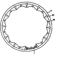
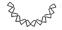
제21도는 종래의 국화형 거르개소자의 사시도.21 is a perspective view of a conventional chrysanthemum filter element.
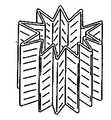
제22도는 본 발명에 관한 크리스탈형 거르개소자의 사시도.22 is a perspective view of a crystal filter element according to the present invention.
* 도면의 주요부분에 대한 부호의 설명* Explanation of symbols for main parts of the drawings
4 : 보강로울러 5 : 제1성형로울러4: reinforcement roller 5: 1st forming roller
5a : 제1절단로울러 6,8 : 아이들로울러5a: 1st cutting roller 6,8: children roller
7 : 제2성형로울러 7a : 제2절단로울러7: 2nd molding roller 7a: 2nd cutting roller
122,130 : 고정가이드 115,131,132 : 가동가이드122,130: Fixed guide 115,131,132: Operation guide
111 : 미는커터 113 : 암커터111: pushing cutter 113: female cutter
9 : 송입로울러 10 : 송입장치9: Feed roller 10: Feeding device
11 : 수축드럼 41,42,41a,42a : 먹임유닛11: shrink
39 : 위치결정로우 93 : 위치결정화살39: positioning row 93: positioning arrow
12 : 이동교체용지그 13 : 인덱스장치12: jig for mobile replacement 13: index device
14 : 공굴림 정형용 슈우트 17 : 먹임로우14: co-rolling orthotic chute 17: feeding low
34 : 먹임봉 50 : 홈34: Feeding Rod 50: Home
본 발명은 테이프형 재료에 부등피치의 파형을 부여하여, 이것을 소정의 단면형상의 소자로 정형하는 기술에 관한 것으로, 특히 자동차엔진용 오일거르개나, 공기거르개용의 소자에 사용되는 여재의 정형공정에 이용되는 것이다. 종전의 사용후 폐기형인 거르개소자는, 일반적으로 수지를 함침한 테이프상인 여재를 파형으로 성형한 것을 다시 원통상으로 둥굴게 정형하고, 이 끝면에 캡을 접착하고, 내측에 프로텍터를 달거나 하여, 형상을 유지한 후, 열풍처리에 의하여 수지를 경화시켜서 완성된다.BACKGROUND OF THE INVENTION 1. Field of the Invention The present invention relates to a technique of imparting an uneven pitch waveform to a tape-like material and shaping it into a device having a predetermined cross-sectional shape. Particularly, a process for shaping media used for an oil filter for an automobile engine or an element for an air filter It is used for. In the conventional used waste filter element, the shape of a tape-impregnated media, generally impregnated with resin, is formed into a round shape again, and a cap is attached to this end surface and a protector is attached to the inside. After maintaining, the resin is cured by the hot air treatment to be completed.
종래부터 일반적으로 널리 사용되고 있는 거르개소자는 제21도에 표시된 것 같은 소위 국화형인 것이 많았으나, 자동차부품의 소형경량화, 고성능화의 추세에 감안하여, 최근에는 제22도에 표시되는 것과 같이 소위 크리스탈형인 것으로 변형되어 가고 있다. 이 크리스탈형인 거르개소자용 여재는 피치가 주기적으로 변화하는 부등피치의 파형이 부여되고 전체로서 그 파형에 의한 미세한 요철(凹凸)을 가짐과 동시에, 최장의 피치를 가진 파형부분이 가장 외측에 위치하며, 피치가 짧아짐에 따라 내측으로 꾸부러져 들어간 굴곡을 가지며, 이것에 의하여 축방향으로 평행인 복수의 틈새구멍을 마련한 다각형상의 단면으로 되어 있다. 그러나, 이와같은 크리스탈형 여제를 합리적으로 제조하는 수단은 아직 개발되어 있지 않다.In general, the filter elements generally widely used have a so-called chrysanthemum type as shown in FIG. 21, but in view of the trend toward miniaturization and high performance of automobile parts, recently, as shown in FIG. It is going to be transformed. This crystal type filter element filter is provided with an uneven pitch waveform whose pitch changes periodically, and has a fine unevenness due to the waveform as a whole, and the waveform portion with the longest pitch is located at the outermost side. As a pitch becomes short, it has the curving | curving inward, and has become a polygonal cross section which provided the some clearance hole parallel to the axial direction by this. However, no means have yet been developed for the rational production of such crystals.
본 발명은 상기한 크리스탈형 거르개소자용 여재를 연속하여 소정의 형상으로 정형하는 일련의 신규의 공정을 제공하는 것을 목적으로 한다.An object of the present invention is to provide a series of novel processes for continuously shaping the above-described medium for crystal filter element into a predetermined shape.
상기한 목적은 원주면에 주기적인 부등(不等)피치의 파형인 요철을 가지며, 상호 대응하는 요철을 기어계합적 상태로 교합시키면서 구동되는 성형, 절단로울러상에 의하여, 테이프상 재료에 소정의 파형을 부여하고, 이것을 상기한 로울러의 표면으로부터 이탈하지 않도록 규제하면서 소정의 길이로 절단하고, 다음에 테이프상 재료에 부여된 최대파형인 부분과, 최소파형인 부분과의 위치를 규제하면서, 아코디언상으로 수축한 상태로 반원형인 단면형상으로 예비정형하여, 이것을 다시 소정의 원형 단면형상까지 축경하면서 정형하는 것을 특징으로 하는 테이프상 재료의 정형방법에 의하여 달성된다.The above-mentioned object is to have predetermined irregularities on the tape-like material by forming and cutting roller images which have irregularities in the circumferential surface which are waveforms of periodic uneven pitch, and are driven while interlocking corresponding irregularities in a gear engagement state. An accordion is provided while giving a waveform, cutting it to a predetermined length while regulating it not to be separated from the surface of the roller described above, and then regulating the position of the portion with the largest waveform and the portion with the smallest waveform, which is next given to the tape-like material. It is achieved by the shaping method of the tape-like material characterized by preliminary shaping | molding to semi-circular cross-sectional shape in the state which shrink | contracted to the shape, and shaping this while shrinking to a predetermined circular cross-sectional shape again.
또한, 이 방법은 테이프상 재료에 주기적인 부등피치인 파형을 부여함으로서, 주변의 이것에 대응하는 요철을 가지고, 상호 대응하는 요철을 기어계합적 상태에서 교합시키면서 구동되고, 또한 소정의 타이밍으로 작동하는 커터를 내장한 적어도 한쌍의 성형, 절단로울러와; 상기한 여재에 부여된 부등피치의 파형의 최대파형부분과 최소파형부분의 위치를 규제하는 로우를 구비하며, 소정의 타이밍으로 테이프상 재료를 간헐적으로 전진시키는 먹임유닛; 그 먹임유닛에 의하여 전진되어진 테이프상 재료를 아코디엔상으로 수축시킨 상태로 내부공간에 수용하여 반원형 단면에 예비정형하는 수축드럼과, 상기한 예비정형된 테이프상 재료의 단면형상에 대응하는 입구와 목적으로 하는 테이프상 재료의 원형 단면형상에 대응하는 출구를 구비하며, 그 사이를 서서히 변화하는 단면형상으로 연결하여 형성된 공굴림 정형 슈우트를 가진 테이프상 재료의 정형장치에 의하여 적절하게 실시된다.Further, this method gives a tape-like material with a waveform that is a periodic uneven pitch, thereby having irregularities corresponding to the surroundings, and driving while interlocking corresponding irregularities in a gear engagement state, and also operating at a predetermined timing. At least one pair of forming and cutting rollers having a built-in cutter; A feeding unit having a row for regulating the positions of the maximum waveform portion and the minimum waveform portion of the waveform of the unequal pitch imparted to the filter medium, and intermittently advancing the tape-like material at a predetermined timing; A shrink drum for preforming a semicircular cross section by accommodating the tape-like material advanced by the feeding unit in an accordion-like state in the inner space, and an inlet corresponding to the cross-sectional shape of the preformed tape-like material described above; It is suitably implemented by the tape-shaped material shaping device which has the exit corresponding to the circular cross-sectional shape of the target tape-like material, and has a co-bending shaping chute formed by connecting therebetween to the gradually changing cross-sectional shape.
이하, 도면에 표시한 적절한 실시예에 기본하여 본 발명을 더욱 상세하게 설명한다.Hereinafter, the present invention will be described in more detail based on the preferred embodiments shown in the drawings.
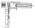
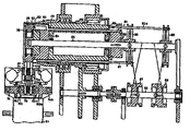
우선, 본 발명에 관한 거르개소자용 여재의 연속정형공정의 전체에 대하여 설명한다. 제1도에 표시하는 바와같이, 본 발명에서는 패키지(P)로부터 되돌려 감겨진 테이프상 여재(1)는 공급로울러(2a)를 구비한 언코일러(2)를 경유하여, 지완상태로 스톡커(3)내에 저류되어, 계속하여 공급로울러(3a)에 의하여 보강로울러(4)로 보내진다. 보강로울러(4)는 한쌍의 서로 접촉하여 회전하는 로울러로 되어 있어서, 그 표면에 길이방향으로 마련된 복수본의 리브에 의하여 여재(1)의 표리양면에 파형으로 대응하는 보강근을 부여하여 다음 공정에서의 파형부여를 용이하게 할 수 있도록 되어 있다.First, the whole of the continuous shaping | molding process of the filter medium for filter elements which concerns on this invention is demonstrated. As shown in FIG. 1, in the present invention, the tape-like media 1 rolled up from the package P passes through the
다음에 여재(1)는 제1성형로울러(5)와 제1절단로울러(5a), 아이들로울러(6) 및 제2성형로울러(7)와 제2절단로울러(7a)로 되어 있는 후술하는 성형 및 절단공정에 보내져서, 파형으로 성형됨과 동시에 거르개 1개분씩인 길이로 절단된다.Next, the medium 1 is formed of a first molding roller 5, a first cutting roller 5a, an idle roller 6, and a second molding roller 7 and a second cutting roller 7a. And it is sent to a cutting process, and it shape | molds into a wave form, and cut | disconnects to the length of one filter.
다음에 여재(1)는 아이들로울러(8)를 지나 송입로울러(9)에 도입되어, 수축장치(10)를 경유, 2개분의 거르개소자용 여재를 수용하는 수축드럼(11)내에 파형으로 접어진 상태로 전체로서 반원형 단면을 하게 충전된다. 이 반원형 단면형상으로 정리된 여재(1)는 제2도에 표시된 바와같이 간헐적으로 상기한 수축드럼(11)으로부터 순차적으로 압출되어 인덱스장치(13)에 방사상으로 장착된 교체이동용축(12)내에 이전되고, 공굴림 정형 슈우트(14)에 도입되며, 그 슈우트내를 순차로 출구측으로 보내짐에 따라, 점차 축경됨과 동시에 원형으로 수정되고, 소망의 크리스탈형 단면이 거르개소자로서 정형된다.Next, the filter medium 1 is introduced into the feed roller 9 through the
이하 각 공정에 대하여 각각 설명한다. 제3도에 기본하여, 성형, 절단공정을 설명한다.Each process is demonstrated below. Based on FIG. 3, the shaping | molding and cutting process are demonstrated.
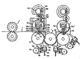
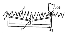
상기한 보강로울러(4)에 의하여 표리면에 소정피치를 보강근이 부여된 여재(1)는 성형, 절단공정에 도입된다. 제1성형로울러(5)와 제1절단로울러(5a)는 여재(1)의 폭에 대응하는 폭을 가지며, 그의 표면에 상기한 여재(1)에 부여되어야 할 파형피치에 대응한 복수(이 예에서는 15개)의 뫼(山)과 골(答)로된 요철을 구비하고, 서로서로 대응하는 요철의 뫼가 다른쪽의 골에 들어가버린 상태(이하, 기어계합적 상태라 칭함)로 회전하도록 적극 구동되어 있다. 이 경우 양 로울러(5), (5a)가 기어계합적 회전을 연속적으로 유지하기 위하여는 한쪽의 로울러 예를들어 성형로울러(5)의 뫼의 정상이 일정직경인 가상원주상에 배열되고(이것을 외경규제라고 칭함), 다른쪽의 로울러, 예를들어 절단로울러(5a)의 골의 저부가 상기한 성형로울러(5)의 가상원주와 동일직경인 원주상에 배열되는 것(이것을 내경규제라 칭함)이 필요하다. 이 관계는 서로서로 기어계합적 상태에서 회전하는 하기의 각 로울러에 대하여도 같은 모양이다.The media 1 provided with a predetermined pitch on the front and back surfaces by the
여재(1)는 보강로울러(4)로 부여된 서로 인접하는 보강근이 꼭 뫼의 정점과 골의 저부에 대면하도록 상기한 보강로울러(4)와 같은 주기로 회전하는 제1성형로울러(5)와 제1절단로울러(5a)로 지지되어, 그의 교합에 의하여 소정의 파형을 연속하여 부여하게 되어 있다. 그리하여, 그 제1성형로울러(5)와 기어계합적 상태를 형성하는 아이들로울러(6)의 표면에 안내되어, 다른 한쌍의 성형로울러(7)와 절단로울러(7a)(제2로울러라고 칭함)와의 계합영역에 도입되도록 구성되어 있다. 각 로울러간의 계합영역 이외에서는 여재(1)는 그 파형변형 때문에, 로울러의 표면으로부터 이탈하는 경향임으로 여재(1)의 반송을 원활하게 하기 위하여는 계합점을 이탈한 여재(1)를 로울러의 표면에 대면하여 마련된 가이드(122), (115), (131), (130), (132)에 의하여 로울러 표면으로부터 이탈하지 않도록 규제할 필요가 있는 것이다.The media 1 is made of a first forming roller 5 and a first rotating roller which rotate at the same period as the
상기한 바와같이 성형로울러(5), (7)는 외경규제의 로울러이므로, 그 뫼의 정점을 연결하는 가상선은 진원으로서 반경은 뫼의 높이에 따라 변화하는 일이 없으므로 이것에 대면하는 가이드(122)와 (130)인 양자는 원호상인 고정가이드로서 설치되는 것이 가능하다. 그러나, 내경규제인 아이들로울러(6)와 제2절단로울러(7a)에서는 뫼의 높이에 따라서, 뫼의 정점이 배열되어 있는 가상선의 반경이 변화하기 때문에, 고정가이드인 경우에는, 뫼의 정점과 가이드와의 거리가 주기적으로 변화하여, 거리가 커진 때는 여재(1)의 통로가 너무 커져, 부여된 파형이 붕괴된다는 결점을 낳게 한다. 이것을 방지하기 위하여 아이들로울러(6)와 제2절단로울러(7a)에 대면하는 가이드(115), (131), (132)는 로울러의 회전과 동주기로 위치를 이동하는 가동가이드로서 구성되어 있다. 이 가동가이드의 구성을 가이드(115)에 관하여 설명한다. 다른 가이드(131)와 (132)는 이와같은 구성이다.As described above, since the forming rollers 5 and 7 are rollers of outer diameter regulation, the imaginary line connecting the vertices of the mew is a circle, and the radius does not change according to the height of the mew. Both 122) and 130 can be provided as fixed guides that are arcuate. However, in the idler roller 6 and the second cutting roller 7a, which are internally regulated, the radius of the imaginary line on which the peaks of the meas are arranged varies depending on the height of the mews. The distance to the guide changes periodically, and when the distance increases, the passage of the medium 1 becomes too large, which causes the disadvantage that the given waveform collapses. In order to prevent this, the
가동가이드(115)는 아이들로울러(6)에 대면하는 원호상의 연부를 가진 판상부재로 구성되어 있다. 그 가이드(115)는 도면에서 상하방향(Y방향)으로 가동한 슬라이더(117)에 고정되어 있고, 그 슬라이더(117)는 도면에서 좌우방향(X방향)으로 가동한 슬라이더(116)상에 설비되어 있다. 양 슬라이더(116)와 (117)는 각각 동주기 회전하는 캠(121)가 (120)에 의하여 구동되는 레버(119)와 (118)에 의하여, 소정의 X, Y방향의 변위를 하도록 구성되어 있다. 이 X, Y방향 변위는 합성되어서 가이드(115)에서 아이들로울러(6)의 뫼의 정점의 궤적에 대응하는 움직임을 주어, 가이드(115)가 항상 아이들로울러(6)에 대하여 일정간격을 가지고 대면하도록 되어 있다. 부호(133), (134)는 레버(118), (119)의 복귀용 스프링이다.The
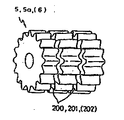
또한, 제4도에 표시한 바와같이, 상기한 제1성형로울러(5)와 제1절단로울러(5a)는 로울러를 폭방향으로 약 3등분하는 위치에 원주방향으로 2줄의 환상홈(200) 및 (201)을 각각 구비하고 있다. 이 홈(200), (201)의 깊이는 로울러(5), (5a)의 표면의 골보다도 깊기 때문에, 따라서 양 로울러(5), (5a)의 계합영역에 있어서도 이 홈(200), (201)의 위치에 있어서도 여재(1)는 잡혀지지되지 않고, 뜬상태가 되어 있다(그러나, 폭의 다른부분에서의 잡혀 지지됨에 따라 성형작용은 충분히 시행된다). 이들 로울러(5), (5a)의 사이에 마련된 상기한 가이드(122)의 한쪽의 끝은 이 홈(200), (201)내에 들어가 박혀져 양 로울러(5), (5a)의 계합영역을 넘어서서, 더욱 상류측에 닿도록 설치되어서, 양 로울러(5), (5a) 사이에서 여재(1)를 확실하게 안내할 수 있도록 되게 되어 있다. 따라서 가이드(122)는 홈(200), (201)내에 들어가도록 동일형상인 2장의 판으로 구성되어 있음이 바람직하다.In addition, as shown in FIG. 4, the first forming roller 5 and the first cutting roller 5a described above have two rows of
한편, 아이들로울러(6)도 제1성형로울러(5)의 상기한 홈(200)에 같은 모양으로 대응하는 2줄의 홈(202)을 가지고 있으며, 상기한 가이드(122)의 다른쪽의 끝은 이 홈(202)내로 들어가 박혀서 양 로울러(6)와 (5)의 계합영역보다 상류측까지 설치되어서, 제1성형로울러(5)의 홈(200)내에 들어가 박힌 가이드(115)의 끝과 협력작동하여, 양 로울러(5)와 (6) 사이의 여재(1)의 받아넘김을 원활하게 하도록 구성되어 있다.On the other hand, the idler roller 6 also has two rows of grooves 202 corresponding to the
제5도에 표시한 바와같이 제2성형로울러(7)와 제2절단로울러(7a)는 로울러의 폭방향 중앙에 원주방향으로 한줄의 환상홈(203), (204)을 각각 구비하고 있다. 이 홈(203), (204)도 상기한 홈(201)등과 같이 구성되어 있다.As shown in FIG. 5, the 2nd forming roller 7 and the 2nd cutting roller 7a are equipped with one row of
또한, 아이들로울러(6)는 상기한 홈(202) 이외에 이 홈(203)에 대응하는 중앙홈(205)도 구비하고 있다(결국 3줄의 홈을 구비하고 있음). 이들의 홈내에는 각 가이드(131), (130) 또는 (132)의 끈이 들어가 박혀, 상기한 제1성형로울러(5), 제1절단로울러(5a)와 아이들로울러(6)의 관계와 같이 각 로울러 사이의 여재(1)의 받아넘김의 원활화를 도모하게 되어 있다. 따라서, 가이드(131), (130), (132)는 한 장의 판으로 구성되어 있음이 바람직하다.In addition to the groove 202 described above, the idler roller 6 also includes a central groove 205 corresponding to the groove 203 (which has three rows of grooves in the end). In these grooves, the strings of the
다음에 이들의 로울러군에 의한 여재(1)의 절단작용에 대하여 설명한다. 테이프상인 여재(1)는 파형으로 성형된 후 거르개소자 1개분의 길이로 절단될 필요가 있다.Next, the cutting action of the media 1 by these roller groups is demonstrated. The media 1 having a tape shape needs to be cut into a length of one filter element after being shaped into a wave shape.
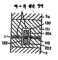
본 발명에서는 상호 계합하여 회전하고 있는 로울러(예를들어 제1성형로울러(5)와 제1절단로울러(5a))에 이것과 동주기 회전을 하는 자웅의 커터를 고정하여 마련하고, 소정길이의 여재가 통과한 시점에서(즉 로울러가 소정회수 회전할 때), 이것을 계합영역에서 작동시킴으로서 절단을 하고 있다. 그러나 각 로울러 사이에서의 여재(1)의 받아넘김을 원활하게 하기 위하여는 상기한 바와같이, 가이드에 따라 잘림없이 완전하게 여재(1)를 안내할 필요가 있으나, 상기한 자웅커터에 의하여 여재를 폭방향으로 한번에 절단하려고 하는 경우, 커터에 의하여 방해되어, 가이드가 양 로울러(5), (5a)의 계합점을 넘어, 더욱 상류측에 들어가 박히는 일이 불가능하게 되기 때문에, 여재의 반송이 불안정하게 되는 것을 피할 수가 없다. 이것을 방지하기 위하여, 본 발명에서는 제1성형로울러(5), 제1절단로울러(5a)의 쌍의 계합영역과 제2성형로울러(7), 제2절단로울러(7a)의 쌍의 계합영역과의 2개소에 있어서, 여재(1)의 동일개소의 폭방향의 상이한 영역을 각각 절단함으로서 절단작업을 완성시키고 있다.In the present invention, the rollers (for example, the first molding roller 5 and the first cutting roller 5a) which are rotated in engagement with each other are fixedly provided and fixed with a male cutter that rotates the same period. At the time when the media passes (that is, when the roller rotates a predetermined number of times), the cutting is performed by operating this in the engagement area. However, in order to smoothly pass the media 1 between each roller, it is necessary to guide the media 1 completely without cutting according to the guide as described above. When trying to cut at the same time in the width direction, the cutter is obstructed and the conveyance of the media is unstable because the guide is prevented from entering the upstream side and getting stuck beyond the engagement point of both rollers 5 and 5a. It can't be avoided. In order to prevent this, in the present invention, the engaging region of the pair of the first molding roller 5 and the first cutting roller 5a, the engaging region of the pair of the second molding roller 7, and the second cutting roller 7a, In two places, the cutting | disconnection work is completed by cut | disconnecting the different area | region in the width direction of the same location of the medium 1, respectively.
즉, 최초는 제6도에 표시하는 바와같이 제1성형로울러(5)와 제1절단로울러(5a)의 폭의 중앙영역에 설치된 제1커터에 의하여 여재(1)의 중앙부만을 절단한다. 이때의 여재(1)의 안내는 로울러의 양측영역에 마련된 상기한 홈(200), (201)에 들어가 박힌 가이드(122)에 의하여 중단함없이 시행된다. 그리하여, 다음에 제7도에 표시하는 바와같이, 제2성형로울러(7)와 제2절단로울러(7a)의 양측영역으로 분할하여 마련된 제2커터에 의하여 아직도 접속상태에 있는 여재(1)의 양측부를 절단하도록 되어 있다. 이 경우, 여재(1)의 안내는 중앙영역에 마련된 상기한 홈(203), (204)에 들어가 박힌 가이드(132)에 의하여 중단함없이 실시된다.That is, as shown in FIG. 6, only the center part of the media 1 is cut | disconnected by the 1st cutter provided in the center area | region of the width | variety of the 1st forming roller 5 and the 1st cutting roller 5a. At this time, the guide of the media 1 is carried out without interruption by the
제3도와 제8도에 기본하여, 이 절단기구를 더욱 상세하게 설명한다.Based on FIG. 3 and FIG. 8, this cutting tool is demonstrated in more detail.
제1절단로울러(5a)의 내부는 중공으로 형성되고, 거기에 수커터(111)가 내장되어 있다. 그 수커터(111)의 끝은 로울러(5a)의 표면의 뫼의 저부에 뚫린 개구를 통하여 출입 가능하게 구성되어 있다. 이 커터(111)는 상기한 바와같이 여재(1)를 폭방향의 중앙영역에서 절단가능한 폭과 위치를 가지고 있다.The inside of the 1st cutting roller 5a is formed in hollow, and the
수커터(111)의 기부는 제8도에 표시하는 바와같이 로울러(5a)의 한 측면으로부터 중공부의 축심에 삽입된 캠(110)와 종동부(111a)를 거쳐 접촉하고, 로울러(5a)의 회전에 따라 그 캠(110)의 주위를 회전하도록 되어 있다.As shown in FIG. 8, the base of the
캠(110)은 로울러(5a)가 회전하여도, 이것과는 같이 돌지 않으나, 로울러(5a)의 다른쪽의 측면으로부터 중공부에 삽입된 축(128)에 대하여 축방향으로 접동자재하게 감합되어 있다.Although the
캡(110)이 축(128)에 대하여 우측으로 움직이면, 캠(110)의 주위의 일부에 마련된 돌기부(110a)가 수커터(111)의 종동부(111a)와 계합가능하게 된다.When the
종동부(111a)가 캠(110)의 돌기부 이외의 부위와 접촉하고 있을 경우는, 로울러(5a)가 회전하여도 수커터(111)는 작동하지 않고, 그의 끝은 로울러(5a)의 내부에 들어가 박힌채로 되어 있으나, 이 돌기부(110a)가 종동부(111a)와 계합하면, 수커터(111)는 눌려져서 그 끝은 상기한 개구로부터 로울러(5a)의 표면에 돌출하도록 구성되어 있다. 이 돌기부(110a)는 로울러(5a)와 (5)의 계합영역에 대응하여 설치되어 있기 때문에, 양 로울러(5), (5a)의 계합영역내에 수커터(111)가 돌출하도록 되게 되어 있다.When the
한편, 제1성형로울러(5)의 내부에도, 수커터(111)에 대응하는 암커터(113)가 고정적으로 내장되어 있어, 그의 마주받이면이 로울러(5)의 골부분의 저부에 노출되어 있다. 이 암커터(113)는 양 로울러(5), (5a)가 계합회전할 때 상기한 수커터(111)와 계합영역에서 회합하는 위치에 설치되어 있다. 따라서, 수커터(111)가 작동위치에 있을 경우, 양커터(111), (113)가 계합하면 여재(1)의 중앙영역이 절단된다.On the other hand, the
다음에 이 수커터(111)를 작동시키는 기구에 대하여 설명한다.Next, a mechanism for operating the
제8도에 표시하는 바와같이 캠(110)의 끝부분은 핀(109)에 의하여 레버(105)의 일단에 축지되어서, 그 레버(105)는 중앙부를 고정축(107)의 일단에 핀(108)으로, 중추적으로 지지되어 더욱이 다른 끝에 마련된 종동부(106)를 거쳐, 홀더(104)에 지지된 홈캠(123)과 계합되어 있다.As shown in FIG. 8, the end portion of the
제1성형로울러(5)와 제1절단로울러(5a)는 서로서로 동일 이빨수의 기어(127)와 (126)에 의하여 연결되어 있는 축(129)과 (128)에 장착되어 있어, 도시하지 않은 구동원으로부터 전달된 회전에 의하여 서로서로 동주기로 기어계합상태로 회전하도록 구성되어 있다.The first forming roller 5 and the first cutting roller 5a are mounted on the
축(128)에는 기어(126)와 동축에 기어(125)가 고정되어 있고 여기에 상비한 캠(123)을 구동하는 기어(124)가 교합하게 되어 있다.The
기어(124)는 기어(125)보다도 이빨수가 많고, 더욱이 양쪽의 이빨수는 정수비가 되어 있다. 이 예의 경우는 3 : 1이다.The
즉, 캠(123)은 로울러(5a)가 3회전하는 사이에 1회전한다. 이 비율은 거르개소자 1개분의 파형의 수에 의하여 적당하게 설정되는 것이다.In other words, the
캠(123)의 작용에 따라, 레버(105)는 지점(108)을 중심으로 하여 요동하며, 그 일단에 중추적으로 지지된 캠(110)은 로울러(5) 및 (5a)가 회전하여 소정길이의 여재(1)를 송출할 때마다, 일회 우측으로 이동하고, 그 돌기부(110a)를 수커터(111)의 종동부(111a)와 계합 가능한 위치에 오도록 하게 되어 있다.According to the action of the
종동부(111a)가 이 위치에 있는 사이에 양 로울러(5), (5a)에 내장된 커터(111)와 (113)가 접촉하여 소정 위치에서 여재(1)의 중앙영역을 절단한다.While the
상기한 바와같이 이 절단시에도 여재(1)는 가이드(122)에 의하여 양측영역에서 안내되게 되어 있다.As described above, the media 1 is guided in both regions by the
제2성형로울러(7)와 제2절단로울러(7a)에 의한 제2단계의 절단도 상기한 것과 실질적으로 동일한 수단으로 이루어진다. 물론, 양 커터(111), (113)의 폭과 위치가 여재(1)의 양측영역에 대응하여 설정되는 것만이 상이한 것이다. 그리하여 커터(111)를 작동시키는 타이밍은, 제1단계의 절단이 시행된 여재(1)의 부분이 제2성형로울러(7)와 제2절단로울러(7a)의 계합영역에 도달한 시점이 되게 맞추는 일이 필요하다. 이것은 모든 로울러가 동주기로 회전하고 있으므로 용이하게 실시 가능하다.The second stage cutting by the second forming roller 7 and the second cutting roller 7a is also made by substantially the same means as described above. Of course, only the widths and positions of the
상기한 절단의 제1단계와 제2단계에서의 여재(1)의 절단영역은 역전할 수가 있는 것이다. 거르개 1개분의 길이에 완전하게 절단된 여재(1)는 계속하여 다음의 수축공정에 도입된다.The cutting area of the media 1 in the first and second steps of cutting can be reversed. The filter medium 1 completely cut to the length of one filter is continuously introduced to the next shrinkage process.
이상과 같이 상술한대로 이 성형 절단공정에 따르면 여재에 부여하여야 할 파형의 요철을 원주면에 구비한 성형로울러와 절단로울러와의 쌍에 의하여 여재를 소정피치의 파형형상으로 성형하면서, 반송할 때 로울러의 파형요철의 정점의 궤도에 대면하는 판형상의 가이드를 로울러의 원주면에 마련된 홈을 통하여 양 로울러의 계합영역까지 삽입하여, 여재가 로울러의 표면으로부터 이탈하지 않도록 완전히 안내하도록 하였기 때문에, 여재의 반송은 안정적으로 확실하게 실시 가능하게 되었다.As described above, according to this forming and cutting step, the rollers are conveyed while forming the media into a waveform having a predetermined pitch by forming a pair of forming rollers and cutting rollers provided on the circumferential surface with irregularities to be provided to the media. Since the plate-shaped guide facing the orbit of the corrugated convex and concave of the corrugation is inserted into the engaging region of both rollers through the groove provided in the circumferential surface of the roller, the media is completely guided so as not to be separated from the surface of the roller. Can be implemented stably and reliably.
또한, 외경규제의 로울러에 대하여는 로울러의 회전에 따라서 비원형궤적을 그리며 이동하는 로울러 표면의 파형요철의 뫼의 정점에 동주기로 변위하는 가동가이드를 마련하여, 항상 로울러 표면과 가이드와의 거리가 일정하게 유지되도록 하였으므로, 상기한 여재통로의 규제가 완전하게 시행된다.In addition, the outer diameter of the roller is provided with a movable guide which is displaced in the same period at the apex of the chamfer of the corrugated irregularities on the surface of the roller, which moves in a non-circular trajectory as the roller rotates, so that the distance between the roller surface and the guide is constant As such, the regulation of the median passage mentioned above is fully implemented.
더욱이 여재를 소재 1개분으로 절단할 때, 제1로울러쌍에서 로울러의 파형요철의 정점의 궤적에 대면하는 판형상인 가이드를 로울러의 원주면의 폭방향의 양측영역(또는 중앙영역)에 마련된 고리형홈을 통하여 양 로울러의 계합영역까지 삽입하여 여재가 로울러의 표면으로부터 이탈하지 않도록 완전하게 안내하면서, 가이드가 되고 있지 않는 중앙영역(또는 양측영역)에 커터를 작용하여 제1절단을 하고, 다음에 제2로울러쌍의 계합영역에 커터를 작용하여 제2단계의 절단을 하고, 절단을 완성하도록 하였기 때문에 여재는 항상 로울러 표면에서 이탈되지 않도록 규재되어 있어서, 절단작업에 의한 여재의 가이드가 중단되는 일은 없다. 따라서 여재를 안정적으로 반송, 절단할 수가 있는 것이다.Furthermore, when cutting the media into one piece of material, annular grooves are provided in the widthwise both sides (or the center area) of the circumferential surface of the roller to guide the plate-shaped guides facing the trajectory of the peaks of the corrugations and convexities of the rollers in the first roller pair. The first cutting is performed by inserting the cutter into the engaging region of both rollers and guiding the media not to deviate from the surface of the roller, by operating the cutter in the center region (or both regions) which is not guided. Since the second step was cut by applying a cutter to the engagement area of the two roller pairs and the cutting was completed, the media is regulated so as not to deviate from the roller surface at all times, so that the guide of the media by the cutting operation is not interrupted. . Therefore, the media can be conveyed and cut stably.
다음에 수축공정에 대하여 설명한다. 제9도에서, 아이들로울러(8)와 송입로울러(9)는 상기한 절단성형로울러등과 같이 원주면에 여재(1)에 부여된 부등피치의 파형에 대응하는 복수의 뫼 및 골로서 이루어진 요철을 구비하고, 서로 기어계합적 상태로 회전하도록 적극적으로 구동되어, 이에 따라 여재에 부여된 부등피치의 파형을 붕괴하지 않도록 유지한 채, 여재를 반송하도록 구성되어 있다.Next, the shrinkage process will be described. In FIG. 9, the
또한, 송입로울러(9)는 여재(1)에 부여되는 파형의 1사이클분인 요철(도시한 예에서는 15개)을 구비하고 있어, 여재(1)는 상기한 절단공정에 따라 거르개소자 1개분의 길이로 절단되어 있는데, 이 길이는 송입로울러(9)의 6회전분에 상당하는 90개의 파형을 갖는다.In addition, the feeding roller 9 is provided with the unevenness | corrugation (15 pieces in the example shown) which is 1 cycle of the waveform provided to the filter medium 1, and the filter medium 1 is a filter element 1 according to the cutting process mentioned above. It is cut into pieces of length, and this length has 90 waveforms corresponding to 6 revolutions of the feeding roller 9.
이 양 로울러(8), (9)는 다같이 외경규제의 로울러로서, 구성되어 있으므로 당연히 그의 골의 저부점은 동일한 원주상에는 배열되지 않는다.Since these
따라서, 양 로울러(8), (9)을 서로 간섭하지 않게 설치하면, 그의 서로 교합하는 뫼의 정점과 골의 저부와의 거리는 항상 일정하지 않고 높은 뫼와 같은 골이 교합할 경우에 상당한 거리가 벌어지게 된다.Therefore, if both the
이 상태로 일반적으로 양 로울러(8), (9)를 회전시킬 경우에는 부여된 여제에 파형이 아이들로울러(8)로부터 송입로울러(9)로 이행할 때, 로울러의 이빨형에서 이탈하여 붕괴 가능성이 생기기 때문에, 본 발명에서는 이것을 방지하기 위하여, 아이들로울러(8)와 동일축에 캠(98)을 마련하고, 그 로울러(8)의 회전에 동주기로 회전하는 것 때문에, 이것에 계합하는 레버(96)를 핀(99)을 중심으로 좌우로 요동시켜, 상기한 바와같이 양 로울러(8), (9)의 교합 틈새가 증가하는 주기에 맞추어, 레버(96)의 배면에서 양 로울러(8), (9)의 잡아 지지하는 점을 떠나는 여재(1)가 송입로울러(9)의 쪽으로 밀어보내어, 여재(1)가 송입로울러(9)의 이빨형으로부터 이탈하지 않도록 규제하고 있는 것이다.In this state, when both the
이렇게 하여, 송입로울러(9)의 표면에 이전한 여재(1)는 로울러(9)의 뫼의 정점의 궤적에 대면하여 마련된 고정가이드(300)에 의하여 통로를 규제당하면서, 확실하게 송입장치(10)에 도입된다.In this way, the medium 1 transferred to the surface of the feeding roller 9 is reliably regulated by the fixed
송입장치(10)는 상부를 수평가이드(301)로 규제된 여재통로(300)와 그 아래쪽에 그 통로에 따라 마련된 2쌍의 먹임유닛(41), (42), (41a), (42a)로서 형성되어 있다. 이 두조의 먹임유닛은 각각 하기하는 이동기구의 슬라이더(74)와 (74a)에 고정되고, 이것에 의하여 여재의 반송방향에 대하여 각조가 서로 역위상의 전진과 후퇴를 반복하도록 구성됨과 동시에, 각조내의 먹임유닛은 각각 제10도의 타이밍표에 표시한대로 상기한 전후운동에 맞추어 승강운동을 하도록 구성되어 있다.The
다음에, 이 두조의 먹임유닛(41), (42), (41a), (42a)에 대하여 상세하게 설명한다.Next, the two sets of feeding
이 두조의 먹임유닛은 상기한 통로(300)의 아래쪽에 그 통로를 폭방향으로 2분하여, 병열로 설치되고, 제11도에 표시하는 바와같이 여재의 진행방향에 대하여 상류측으로부터 하류측에 (41), (42), (41a), (42a)의 순서로 배열되어 있다.The two sets of feeding units are provided in parallel with the passage in the width direction at the bottom of the
먹임유닛(41)은 I자형 단면인 1개의 토우(I)만으로 되어 있으며, 먹임유닛(42)은 2개의 I자형 단면인 토우(I)와 1개의 Y자형 단면인 토우(Y)가 도시한 바와같이 교호로 배열되어 있다.The
한편, 먹임유닛(41a)은 1개의 토우(Y)만으로 되어 있고, 먹임유닛(42a)은 2개의 토우(Y)와 1개의 토우(I)가 교호로 배열된 구성으로 되어 있다.On the other hand, the feeding unit 41a has only one tow Y, and the feeding unit 42a has a configuration in which two tows Y and one tow I are alternately arranged.
그리하여, 먹임유닛(41), (42)의 각 토우 및 먹임유닛(41a), (42a)의 각 토우는 각각 등간격으로 늘어서 있게 되어 있다.Thus, the tows of the feeding
이 먹임유닛에 의한 여재의 송입작용에 대하여 설명한다. 우선, 송입로울러(9)의 최대의 골(9a)이 회전하여 통로(300)의 입구에 접근한 시점에서, 후단위치에 대기하고 잇는 먹임유닛(41)은 전진을 개시함과 동시에 상승하고, 그 토우(I)는 아래쪽으로부터 통로(300)의 입구의 위치에서 로울러(9)의 상기한 골(9a)에 합치하며, 그 골(9a)에 지지되어 있는 여재(1)의 최대파형을 아래쪽으로부터 지지하며, 앞쪽으로 반송하게 된다.The feeding function of the media by this feeding unit is demonstrated. First, when the
이 시점에서 다른쪽의 조의 먹임유닛(41a), (42a) 쪽은 하강위치에 있어서, 후퇴운동을 하고 있다.At this point, the feeding units 41a and 42a of the other jaw are in a retracted position in the lowered position.
다음에, 상기한 송입로울러(9)의 최소의 (9b)(이것은 상기한 최대골(9a)에서 180°인 각도 위치에 있음)가 통로(300)의 입구에 접근한 시점에서, 기히 후단위치에 도달하여 대기하고 있는 먹임유닛(41a)은 전진을 개시함과 동시에 상승하여, 그 토우(Y)는 그 뫼(9b)에 지지되어 있는 여재(1)의 최소의 파형을 아래쪽으로부터 지지하여 앞쪽으로 반송한다.Next, at a time when the minimum 9b of the feeding roller 9 (which is at an angular position of 180 ° from the
이 동작의 반복에 따라 여재(1)는 부여된 파형을 유지한 채로 순차적으로 통로(300)내에 송입된다.In response to the repetition of this operation, the filter medium 1 is sequentially fed into the
먹임유닛(41), (42)이 여재(1)의 최초의 최대파형(최소파형)을 지지하여 전진하고, 그 앞끝위치에 도달하는 사이에 한쪽의 먹임유닛(41a), (42a)은 후퇴하여 그 뒤끝 위치에 도달함과 동시에 정지한다.While the feeding
이 위치에서 양 먹임유닛(41), (42), (41a), (42a)은 제11도에 표시한 바와같이 전자의 토우가 후자의 토우보다 1피치분만큼 선행한 상태가 되어, 동일 종류의 토우끼리가 인접하여 병열된다.In this position, the
이 상태로부터, 먹임유닛(41), (42)이 후퇴운동으로 이행할 때(이 시점에서 다른쪽의 조의 먹임유닛은 뒤끝위치로부터 전진운동으로 이행한다), 먹임유닛(41), (42)은 하강하여, 여재의 지지를 해방하나, 동시에 다른쪽의 먹임유닛(41a), (42a)은 상승을 개시하고, 여재(1)가 먹임유닛(41), (42)으로부터 해방되기 전에 이것을 지지하며, 두조의 먹임유닛 사이에서의 여재(1)의 바꾸어잡기가 시행된다.From this state, when the feeding
그리하여, 계속되는 먹임유닛(41a), (42a)의 전진운동에 의하여 여재(1)는 다시 전진시켜지는 것이다.Thus, the filter medium 1 is advanced again by the continuous movement of the feeding units 41a and 42a.
이 바꾸어잡기에 의하여 여재(1)는 반송 중 항상 한쪽의 먹임유닛(42) 또는 (42a)의 토우에 의하여 그 최대파형과 최소파형과를 보존 지지되는 일이 가능하게 된다.By this change, the medium 1 can always hold and hold the maximum waveform and the minimum waveform by the tow of one
이상의 운동을 반복함으로서, 여재(1)는 제12도에 보여주는 바와같이 정연하고 확실하게 토우(I) 및 (Y)에 의하여 순차로 통로(300)내를 반송되어서, 다음의 수축드럼(11)내로 도입된다.By repeating the above-described movement, the media 1 is conveyed in the
또한 상기한 수평가이드(301)는 토우(I), (Y)의 상승에 따라 여재(1)가 떠올라가지 않도록 규제하는 작용을 하고 있는 것이다.In addition, the
다음에 상기한 먹임유닛의 운동을 시키기 위한 기구에 대하여 설명한다.Next, a mechanism for exercising the above feeding unit will be described.
제13도 및 제14도에서, 먹임유닛(41), (42)은 슬라이더(74) 위에 고정되고, 먹임캠(61)에 장착된 기어(70)에 의하여, 슬라이더(74)와 일체적으로 마련된 랙(153)을 경유하여, 여재의 반송방향으로 왕복운동하게 가능하게 구성되어 있다.13 and 14, the feeding
제13도에서 분명한대로, 먹임유닛(41a), (42a)은 상기한 먹임유닛(41), (42)과 평행으로 슬라이더(74a)위에 고정되며, 이것에 고정된 랙(153a)을 경유하여 상기한 기어(70)에 의하여 슬라이더(74)와 반대방향으로 왕복운동 가능하게 구성되어 있다.As is apparent from FIG. 13, the feeding units 41a and 42a are fixed on the slider 74a in parallel with the
이것에 의하여 상기한 먹임유닛의 전진후퇴운동이 시행된다. 먹임유닛(41), (41a)에는 각각 캠(45), (45a)이 관련하여 슬라이핀(71), (72a)을 상하방향으로 운동시켜서 토우를 승강시키도록 구성되어 있다.Thereby, the forward and backward movement of the feeding unit is performed. The feeding
같은 모양으로 먹임유닛(42), (42a)에도 각각의 캠(46), (46a)이 관련하여((46)은 제14도 참조, (46a)는 도시않음), 토우를 승강시킨다.The cams 46 and 46a are also associated with the feeding
이에 따라, 상기한 각 토우의 승강운동이 시행된다.Accordingly, the lifting motion of each tow is performed.
이들 기구의 구동은 송입로울러(9)의 회전이 기준이 되며, 그 로울러가 1 회전하면 슬라이더가 1 왕복하고, 캠이 1 회전하도록 구성되어 있다.The driving of these mechanisms is based on the rotation of the feed roller 9, and when the roller rotates once, the slider reciprocates once and the cam rotates once.
다음에 수축드럼(11)에 대하여 설명한다.Next, the
그 수축드럼(11)은 제13도에 표시한 바와같이, 상기한 통로(300)에 대하여, 직교하는 방향으로 연장되어 있는 고정축(65)을 중심으로 하고, 회전자재하게 장착된 주축(66)의 선단부에는 보조호울더(64)에 장착된 호울더(63)가 고정되어 있다.As shown in FIG. 13, the
그 호울더(63)에는, 이것을 원주에 따라 12등분한 위치에 반경방향으로 홈이 마련되어 있어, 여기에 제16도에 표시한 바와같은 형상의 12개의 위치선정토우(39)가 접동자재하게 감합되어 있으며, 주축(66)과 함께 축(65) 중심으로 회전하도록 구성되어 있다.The
이 토우(39)는 스프링(38)에 의하여, 수축드럼(11)의 외측하우징(62)의 내면에 향하여 반경방향으로 튕겨지게 되어 있다.The
이 토우(39)의 위치에 대응하는 그 하우징(62)의 아래쪽 부분은 제14도의 위치(D)의 근방에 상기한 통로(300)에 향하여 개방되어 있다.The lower portion of the housing 62 corresponding to the position of the
따라서, 이 부분에서 통로(300)를 반송되어 온 여재(1)는 정지상태인 하우징(62)의 내측에 진입가능하게 되어 있어, 또한 토우(39)는 그 통로(300)를 차단하도록 돌출가능하게 되어 있다.Therefore, the media 1 which conveyed the
상기한 위치(D)는 상기한 먹임유닛(42)의 최선단위 여재(1)의 최소파형부를 지지함)토우(Y)의 전진운동의 앞끝위치에 대응하고 있다.The position D corresponds to the front end position of the forward movement of the tow Y, which supports the minimum waveform portion of the uppermost unit media 1 of the
또한, 상기한 토우(39)의 작용은 먹임유닛(42)의 선단의 토우(Y)가 여재(1)의 최소파형을 위치(D)까지 반송한 시점에 순차로 강하하여 토우(Y)와의 사이에 여재(1)의 최소파형을 잡아서 지지하고, 다음에 주축(66)의 회전에 따라, 그대로 하우징(62)의 내면과의 사이에서 잡혀 지지하여, 위치선정작용을 갖도록 되어 있다.In addition, the above-described action of the
한편, 상기한 각 위치선정토우(39)의 사이에 위치에 축방향으로 접동자재한 12개의 위치선정화살(93)이 축(84)의 선단에 지지되어, 슬라이드 배어링(150), (151)을 경유하여 상기한 주축(66)에 장착되어, 이것과 함께 회전하도록 구성되어 있다.On the other hand, twelve
이 위치선정화살(93)은 상기한 먹임유닛(42a)의 최선단의 토우(I)가 전진운동의 앞끝위치(D)까지 여재(1)의 최대파형을 반송한 시점에서, 수평방향으로 순차적으로 통로(300)위에 돌출하고, 이 최대파형을 옆으로부터 지지하여, 그대로 하우징(62)내에 가지고 가서, 상기한 위치선정 토우(39)와의 공동작업으로 여재(1)의 파형을 붕괴함없이 수축드럼(11)내에 잡아 지지하면서 다음 공정에 반송하는 작용을 한다.The positioning
이와같이 교호로 이 동작을 반복함으로서, 하우징(62)과 호울더(63)와의 사이에, 위치선정토우(39)와 화살(93)에 의하여 차단되면서 순차로 여재(1)가 송입된다.By repeating this operation alternately in this manner, the filter medium 1 is sequentially inserted while being blocked by the
이때, 먹임유닛과의 전진속도와 주축(66)의 원주속도와의 차가 있기 때문에, 여재(1)는 아코디온상으로 수축되어 수축드럼(11)내에 수용된다.At this time, since there is a difference between the advancing speed with the feeding unit and the circumferential speed of the main shaft 66, the filter medium 1 is contracted onto the accordion and accommodated in the shrinking
이와같이 하여, 수축드럼(11)내에 수용된 여재(1)의 상태를 제16도에 보여준다.In this way, the state of the media 1 accommodated in the shrinking
인접한 토우(39)의 사이에는 상기한 송입로울러(9)의 1 회전분의 길이의 여재(1)가 수용되어 있다는 것은 상기한 설명으로 명백하다.It is apparent from the above description that the medium 1 having the length of one rotation of the feed roller 9 is accommodated between the
따라서, 드럼(11) 전체로서는 송입로울러(9)의 12 회전분인 여재(1)가 수용되는 것이 된다. 그런데 상기한 바와같이 거르개소자 1 개분의 여재의 길이는 송입로울러(9)의 6 회전분의 길이이기 때문에 수축드럼(11)이 1 회전하는 동안 거르개소자 2개분의 여재가 그의 내부에 수용되는 것이 된다.Therefore, as the
따라서, 수축드럼(11)이 1 회전하여 시발위치에 돌아올 때까지의 사이에 먼저 수용되었던 거르개소자 1개분의 여재(1)를 밀어내어, 위치(D)에는 빈 것이 된 공간이 진행하도록 되어 있다. 밀어내진 반원형으로 성형된 여재(1)는 후속하는 인덱스장치(13)의 주위에 장착된 이동교체용 지그(12)내에 밀어넣어져서 유지된다.Accordingly, the media 1 for the filter element, which was accommodated first, is pushed out until the
다음에 각 수축드럼(11)의 각부를 작동시키는 기구에 대하여 설명한다.Next, a mechanism for operating each part of each of the contraction drums 11 will be described.
제14도에서 상기한 수평가이드(301)의 상부에는 각 위치 선정토우(39)의 움직임을 규제하는 캠(37)이 설치되어, 주축(66)이 회전함에 따라, 이 캠(37)에 접촉한 토우(39)는 커어브에 따라 순차로 그 주축(66)의 중심방향으로 밀려서, 스프링(38)의 튕기는 힘에 대향하여 하우징(62)의 내부로 쏙 들어간다. 그리하여, 상기한 위치(D)에 이르면, 캠(37)로부터 떨어져서 다시 외측에 돌출하여 여재(1)의 최소파형을 지지하는 작용을 한다.In FIG. 14, a cam 37 for regulating the movement of each
제13도에서, 상기한 위치선정화살(93)을 담당 지지하는 축(84)의 후단은, 축(65)에 고정되어 있는 홈캠(85)에 종동부를 경유하여 계합되어 있으며, 주축(66)이 축(65)을 중심으로 하여 회전함에 따라 화살(93)을 축에 평행으로 수평방향으로 접동시킨다.In FIG. 13, the rear end of the shaft 84 supporting the
그리하여 제14도에 표시하는 위치(D)의 시점에서 전진을 개시하여, 여재(1)의 최대파형에 횡방향으로 들어가 끼어, 이것의 위치를 정한다는 것은 상기한 바와같다. 그리하여, 이대로의 상태로 위치(A)로부터 (C)에 도달하면, 이번에는 후퇴를 시작하여 위치(D)에 이르기까지의 사이에 수축드럼(11)내에 끌려 들어가게 되므로 구성되어 있다.Thus, advancement is started at the time of the position D shown in FIG. 14, and it enters the maximum waveform of the medium 1 in the transverse direction and determines the position thereof as described above. Thus, when the position A to the position C is reached in this state, it is configured to be retracted into the
수축드럼(11)내에 수용되어 있는 여재(1)를 밀어내기 위한 24개의 밀어내기봉(83), (83a)이 각각 드럼(11)의 각 반원주마다 상기한 각 위치선정토우(39)와 각 화살(93)의 중간에 주축(66)을 관통하여, 축방향으로 접동자재하게 끼워 맞추어져 있다.Twenty-four push rods 83 and 83a for pushing out the media 1 contained in the
이들 밀어내기봉(83), (83a)은 고정축(65)에 접동자재하게 장착된 링(86), (88)에 각각 모아서 장착되어 있고 링(86), (88)은 캠축(92)에 고정된 캠(87), (89)에 의하여 도시하지 않은 레버를 경유하여 좌우로 요동가능하게 구성되어 있다.These push rods 83 and 83a are collectively mounted on the rings 86 and 88, which are slidably mounted to the fixed
그리하여 수축드럼(11)내에 수용된 거르개소자 1개분의 여재(1)의 선두부분이 위치(B)에 도달하고, 후단부분이 위치(A)에 도달한 시점에서 그 여재를 수용하고 있는 반원주에 위치하고 있는 절반의 밀어내기봉(83) 또는 (83a)가 전진을 개시하며, 드럼(11)이 위치(B)로부터 (C)까지 회전하는 사이에 여재(1)를 횡방향으로(제13도에서 좌측에) 밀어내어 도시하지 않은 이동교체 지그(12)에 이전한다.Thus, at the time when the leading part of the filter element 1 for one filter element accommodated in the shrinking
이와같이 거르개소자 1개분의 여재(1)가 위치선정토우(39)와 위치선정화살(93)로 차단되어서, 그 드럼(11)의 회전에 따라서 시발점위치(D)에서 180°의 분각에 걸쳐 수축상태로 수용된 것을 다시 그 시발점위치(D)에 도달하기 전에, 밀어내기봉(83), (83a)의 작용에 의하여 반원형상을 유기한 체, 이동교체지그(12)내에 이전시키는 것을 반복함으로서, 연속적으로 예비정형된 여재를 작성할 수가 있다.In this way, the filter medium for one filter element is cut off by the
또한, 제13, 14도에 표시한대로 캠축(92)은 주축(66)과 동일 회전하도록 구성되어 있고, 또한 송입로울러(9)의 회전수와 수축드럼(11)의 회전수의 비는 12 : 1이 되게 구성되어 있다.13 and 14, the cam shaft 92 is configured to rotate in the same manner as the main shaft 66, and the ratio of the rotation speed of the feed roller 9 and the rotation speed of the
이와같이 본 발명의 수축공정에 따르면, 송입로울러의 뫼형의 회전위상에 맞추어 먹임유닛의 송강타이밍과 전진후퇴타이밍을 결정하였으므로 이것에 의하여 부등피치인 주기적 파형을 부여된 여재의 최대 및 최소파형의 위치를 확실하게 잡어 지지하여 수축드럼내로 송입할 수가 있는 것이다.As described above, according to the shrinkage process of the present invention, the feed timing and the forward retreat timing of the feed unit are determined in accordance with the rotational phase of the feed roller, and thus the position of the maximum and minimum waveforms of the medium given the periodic waveform, which is inequality, is determined. It can be held firmly and fed into the shrinking drum.
또한, 수축드럼내에 있어서도, 먹임유닛으로부터 받아넘겨진 여재를 위치선정토우 및 화살에 의하여 위치규제를 하면서, 드럼내에 수용하도록 하였으므로, 여재는 임의 부여된 부등피치의 파형을 붕괴함없이 안정되어 반원형상으로 예비정형된다.In addition, even in the contraction drum, the media delivered from the feeding unit were accommodated in the drum while positioning by means of positioning tow and arrows, so that the media was stabilized without collapsing the waveform of the randomly given inequality pitch in a semicircular shape. Preformed.
이에 따라 계속되는 공굴림 공정을 원활하게 실시할 수가 있는 것이다.Thereby, the continuous co-rolling process can be performed smoothly.
상기한 수축드럼(11)으로부터 이동교체용 지그(12)에 이전된 여재(1)은 제17도 a)에 표시한 반원형의 단면을 하고 있다.The filter medium 1 transferred from the
이것을 서서히 제17도 n)에 표시한 원형의 단면까지 공굴림하여 축소정형하는 것이, 공굴림 공정의 목적인 것이다.The purpose of the co-bending process is to gradually roll and co-roll this to the circular cross section shown in FIG.
제2도에 표시한 바와같이 수축드럼(11)에 대면한 이동교체용 지그(12)내에 여재(1)가 이전하면, 인덱스장치(13)는 일정분각 만큼 회전하여 선행하는 지그(12)내의 여재(1)를 공굴림하고, 정형용 슈우트(14)의 입구(14a)와 대면되게 한다.As shown in FIG. 2, when the media 1 moves in the
제18도 및 제19도에 표시한 바와같이 그 공굴림 정형용 슈우트(14)는 밑판(15)위에 연재하여 마련되어서, 그 축에 수직인 단면은, 가장 가까운 쪽의 상기한 입구(14a)(도면에서 우단)로부터 가장 먼 단부에 마련된 출구(14n)(도면에서 좌단)까지 상기한 제17도에 보여주는 여재(1)의 단면에 따라 서서히 좁게 되면서 점차로 원형으로 변형하는 공간(1′)(제20도 참조)을 갖는다.As shown in Figs. 18 and 19, the
상기한 밑판(15)에는 슈우트(14)에 따라 2개의 홈(50)이 마련되어 있다.The
또한, 상기한 밑판(15)의 아래쪽에는 먹임봉(34)이 슈우트(14)의 길이방향에 따라 마련되고, 이것에 복수쌍(이 예에서는 13쌍)의 먹임토우(17)가 일정한 피치로 수직으로 고정되어 있다.In addition, a feeding
이 먹임봉(34)에는 하기하는 이동기구(51)가 장착되어 있고, 이에 의하여 간헐적으로 일련의 상승운동, 전진운동, 하강운동, 후퇴운동을 반복하도록 구성되어 있다.This feeding
상기한 먹임토우(17)는 이 먹임봉(34)의 상승운동에 의하여 홈(50)을 관통하여 슈우트(14)의 내부의 각 여재의 사이의 틈새에 들어가 박힐 수가 있어, 전진운동에 의하여, 슈우트(14)내의 각 위치에 있는 여재를 밀어 넣어서 다음의 위치에 전진시켜, 하강운동에 의하여 다시 슈우트(14)밖으로 이탈하며, 후퇴운동에 의하여 원위치로 복귀할 수가 있다.The feeding
물론 먹임봉(34)의 전진후퇴의 거리는 상기한 먹임토우(17)의 장착피치와 동등하게 설정되어 있다.Of course, the distance of the forward retreat of the
처음, 이동교체용 지그(12)(밑에 상기한 홈(50)에 대응하는 홈이 마련되어 있음)내로부터 슈우트(14)의 입구에 먹임토우(17)에 의하여 이전된 여재(1)는 먹임토우(17)에 의하여 슈우트(14)내를 순차로 출구(14n)측에 보내져서, 그때마다 서서히 축소되며, 또한 완전한 원형단면으로 정형된다.First, the media 1 transferred by the feeding
먹임토우(17)가 슈우트(14)내에 삽입된 상태를 제20도의 횡단면도에 예시한다.The state where the
여재(1)는 심재(32)와 외벽(31)의 틈사이의 공간(1′)내에 수용되어 있다.The filter medium 1 is accommodated in a space 1 'between the core 32 and the gap between the outer wall 31.
여재의 정형상태를 제17도 a)로부터 제17도 n)까지에 도시한다.The steady state of the media is shown in Figure 17 a) through Figure 17 n).
각 도면에서 실제로는 a) 및 n)와 같이 미세한 파형이 부여되어 있으나, 도면을 간략화하기 위하여 연속하는 뫼 및 골 끼리를 연결하는 선에 의하여 이것을 대응하고 있는 점에 유의하기 바란다.In the drawings, fine waveforms are actually provided as shown in a) and n). However, in order to simplify the drawings, it should be noted that these lines are corresponded by lines connecting continuous mews and valleys.
다음에 상기한 먹임봉(34)의 이동기구(51)에 대하여 제19도를 기본하여 설명한다.Next, the above-described moving
상기한 밑판(15)은 고정비임(33)에 장착된 스탠드(18)위에 지지되어 있다. 그 비임(33)의 중앙영역에서는 브래킷(22)에 지지된 수평방향의 파이롯봉(23)이 마련되어 있어, 이것에 슬라이더(35)가 미끄럼 자재하게 장착되어 있다.The
이 슬라이더(35)에는, 수직방향인 슬라이더(20)가 고정되어 있고, 이것에 마련된 홈내에 상기한 먹임봉(34)의 중앙에 마련된 종동부(21)가 계합되어 있다.The
또한, 상기한 비임(33)의 아래쪽에는 구동축(36)이 설치되어, 이것에 캠(25)이 장착되고, 구동축(36)의 회전에 의하여 상기한 슬라이더(35)의 하연에 마련된 랙과 교합하는 섹터(24)를 좌우로 회동시키도록 구성되어 있다.In addition, a drive shaft 36 is provided below the
이것에 의하여 구동축(36)이 회전하면, 캠(25)이 회전하여, 슬라이더(20). 종동부(21)를 경유하여 먹임봉(34)를 좌우로 움직이는 것이 가능하게 되어 있다.When the drive shaft 36 rotates by this, the
상기한 구동축(36)에는 한쌍이 캠(28a), (28b)이 고정되어 있고, 이것에 수직방향인 파이롯봉(26a), (26b)이 각각 종동부(29a), (29b)를 경유하여 계합하여, 구동축(36)의 회전에 의하여, 비임(33)에 장착된 보스(27a), (27b)를 통하여 상하운동 가능하게 구성되어 있다.A pair of
이 파이롯봉(26a), (26b)의 선단에는 슬라이더(52a), (52b)가 고정되어 있어, 그 슬라이더는 브래킷(19)에 의하여 상기한 먹임봉(34)의 아래쪽에 고정된 수평방향의 파이롯봉(53a), (53b)에 미끄럼 자재하게 계합되어 있다.Sliders 52a and 52b are fixed to the ends of the
이것에 의하여, 구동축(36)이 회전하면, 캠(28a), (28b)가 회전하고, 파이롯봉(26a), (26b), 슬라이더(52a), (52b)를 경유하여, 먹임봉(34)을 상하로 움직이는 일이 가능하게 되어 있다.As a result, when the drive shaft 36 rotates, the
이들의 상하운동의 거리는 상기한대로 봉(34)의 상승시에 먹임토우(17)가 홈(50)을 통하여 공굴림 정형 슈우트(14)의 내부에 삽입되어, 하강시에는 이것으로부터 완전히 이탈할 정도로 설정되고 또한 전후(좌우)운동의 거리는 각 먹임토우(17)의 장착 피치에 동등하게 설정되어 있다.The distance of these vertical movements is such that the
또한 상하, 전후운동의 타이밍은 상승-전진-하강-후퇴의 순서가 정연하게 시행되도록 설정되어 있다.In addition, the timing of the up, down, back and forth movement is set so that the order of the up-forward-down-retreat is performed squarely.
더욱이 2줄의 홈(20)은 여재가 축소됨에 따라 슈우트(14)의 폭이 점차로 좁혀지는 것에 맞추어, 도중에서 간격이 변경되어 있다.Furthermore, the two rows of
이것에 동반하여 먹임토우(17)의 쌍의 간격은 제18도에 보여주는 바와같이 변경되어 있다.Accompanying this, the spacing of the pairs of feed tows 17 is changed as shown in FIG.
이와같이 본 발명의 공굴림 공정에서는 반원형 단면으로 예비 정형된 여재를 먹임토우의 운동에 의하여 공굴림 정형용 슈우트의 입구에 도입하여, 이것을 1피치씩 전진시켜서, 그 슈우트의 단면형상의 변화에 따라 점차로 형을 변경시켜, 출구에서 소망의 완전 정형된 여재를 얻으므로 그 운동에 무리가 없으며, 또한, 연속하여 여재의 정형을 할 수가 있는 것이다.As described above, in the co-bending process of the present invention, the media preliminarily shaped into the semi-circular cross section is introduced into the inlet of the co-bending shaping chute by the movement of the feeding tow, and then advanced by one pitch, and according to the change of the cross-sectional shape of the chute. By gradually changing the shape, the desired perfectly shaped media can be obtained at the exit, so that the movement can be made smoothly, and the media can be shaped continuously.
이상 상세히 기술한대로 본 발명에 따르면 서로 대응하는 요철부를 교합시켜서, 기어계합적 상태에서 적극 구동되는 로울러쌍에 의하여, 소정의 부등피치의 파형을 테이프상 재료에 부여함과 동시에 이 파형을 붕괴하지 않도록 교묘하게 여재를 가이드하면서, 소정의 위치에서 절단하고, 또한 여재의 최대, 최소의 파형부의 위치를 확실하게 유지, 규제하면서 수축드럼내에 송입하여 반원형 단면으로 예비정형하고, 최후에 공굴림 정형용 슈우트에 의하여 무리없이 소망의 원형단면인 거르개소자로서 완성하는 것이다.As described in detail above, according to the present invention, a pair of rollers that are actively driven in a gear engagement state by interlocking corresponding uneven portions to impart a waveform of a predetermined uneven pitch to the tape-like material and not to collapse the waveform. While carefully guiding the media, the media is cut at a predetermined position and fed into the shrinking drum while preserving and regulating the position of the maximum and minimum corrugations of the media, and preformed into a semi-circular cross section. It is to be completed as a filter element which is a desired circular section without difficulty.
이들 각 공정은 연속하여 자동적으로 실시 가능하며, 종래의 제조공정에 비하여, 현격하게 생산성이 향상함과 동시에 안정된 품질의 제품을 얻을 수가 있는 것이다.Each of these steps can be carried out automatically and continuously. Compared with the conventional manufacturing steps, the productivity can be significantly improved and a product of stable quality can be obtained.
Claims (11)
Applications Claiming Priority (10)
| Application Number | Priority Date | Filing Date | Title |
|---|---|---|---|
| JP61168144A JPS6325029A (en) | 1986-07-18 | 1986-07-18 | Method and device for cutting material molded in corrugated manner |
| JP168144 | 1986-07-18 | ||
| JP169935 | 1986-07-21 | ||
| JP61169935A JPS6327240A (en) | 1986-07-21 | 1986-07-21 | Method and device for carrying material molded in corrugated manner |
| JP61189642A JPS6349209A (en) | 1986-08-14 | 1986-08-14 | Method and device for rounding material formed to wave shape |
| JP205786 | 1986-08-14 | ||
| JP189642 | 1986-08-14 | ||
| JP61205788A JPS6362513A (en) | 1986-09-03 | 1986-09-03 | Method and device for forming tape material |
| JP61205786A JPS6362512A (en) | 1986-09-03 | 1986-09-03 | Method and device for contracting corrugated molded body |
| JP205788 | 1990-07-31 |
Publications (2)
| Publication Number | Publication Date |
|---|---|
| KR880001422A KR880001422A (en) | 1988-04-23 |
| KR900004542B1 true KR900004542B1 (en) | 1990-06-29 |
Family
ID=27528447
Family Applications (1)
| Application Number | Title | Priority Date | Filing Date |
|---|---|---|---|
| KR1019870007461A Expired KR900004542B1 (en) | 1986-07-18 | 1987-07-11 | A method and apparatus for the preparation of a filtering element |
Country Status (4)
| Country | Link |
|---|---|
| US (1) | US5120296A (en) |
| KR (1) | KR900004542B1 (en) |
| DE (1) | DE3723757C2 (en) |
| GB (1) | GB2194564B (en) |
Families Citing this family (25)
| Publication number | Priority date | Publication date | Assignee | Title |
|---|---|---|---|---|
| US5383837A (en) * | 1991-04-05 | 1995-01-24 | Patriot Packaging Corporation | Method and apparatus for making improved dunnage |
| US5316828A (en) * | 1991-04-25 | 1994-05-31 | Miller Ray R | Reinforced fluted medium and corrugated fiberboard made using the medium |
| JP2714278B2 (en) * | 1991-08-20 | 1998-02-16 | 三井化学株式会社 | Filter and its manufacturing device |
| GB9124249D0 (en) * | 1991-11-14 | 1992-01-08 | Goldstein Fredric | Ribbon curling and shredding device |
| US5543047A (en) | 1992-11-06 | 1996-08-06 | Pall Corporation | Filter with over-laid pleats in intimate contact |
| US5403482A (en) * | 1993-10-12 | 1995-04-04 | Gelman Sciences Inc. | Self-supporting, pleated, spirally wound filter and the corresponding process of making |
| US5899447A (en) * | 1997-09-02 | 1999-05-04 | The Procter & Gamble Company | Apparatus for stacking pop-up towels |
| US6298639B1 (en) | 1998-05-08 | 2001-10-09 | Berwick Industries, Inc. | Method and associated apparatus for imparting a helical curl ribbon material for making a decorative element |
| US6283907B1 (en) | 1998-05-15 | 2001-09-04 | Berwick Delaware, Inc. | Method and associated apparatus for imparting a helical curl to ribbon material for making a decorative element |
| US6074592A (en) * | 1998-07-20 | 2000-06-13 | Berwick Delaware, Inc. | Method for imparting curl to ribbon material |
| AU765826B2 (en) | 1999-01-07 | 2003-10-02 | 3M Innovative Properties Company | Pleated filter element and method of forming a pleated filter element |
| EP1453588B1 (en) * | 2001-12-03 | 2010-06-30 | Donaldson Company, Inc. | Filter element using corrugated media sheet |
| WO2005037408A1 (en) * | 2003-10-14 | 2005-04-28 | Donaldson Company, Inc. | Filter assembly with pleated media v-packs, and methods |
| DE102004042410A1 (en) * | 2004-09-02 | 2006-03-09 | Mahle Filtersysteme Gmbh | Filter medium for a fluid |
| US7931723B2 (en) * | 2006-03-09 | 2011-04-26 | Donaldson Company, Inc. | Filter assembly with pleated media pockets, and methods |
| EP2514506B1 (en) | 2007-02-02 | 2019-08-14 | Donaldson Company, Inc. | Air filtration media pack and methods |
| CN105381650B (en) | 2007-06-26 | 2018-05-29 | 唐纳森公司 | Filter medium bag, filter element and method |
| EP2268380B1 (en) | 2008-02-04 | 2019-09-25 | Donaldson Company, Inc. | Method and apparatus for forming fluted filtration media |
| BRPI0915931B1 (en) | 2008-07-25 | 2020-03-31 | Donaldson Company, Inc. | PACKAGES OF PREGUE FILTERING AGENTS |
| MX2012001455A (en) * | 2009-08-03 | 2012-05-08 | Donaldson Co Inc | Method and apparatus for forming fluted filtration media having tapered flutes. |
| KR101102317B1 (en) * | 2009-09-29 | 2012-01-03 | (주)케이아이웍스 | Auto Injection Ampoule Cap |
| MX2012008542A (en) | 2010-01-25 | 2012-11-12 | Donaldson Co Inc | Pleated filtration media having tapered flutes. |
| EP2384694A1 (en) | 2010-05-05 | 2011-11-09 | Roche Diagnostics GmbH | Method for producing a membrane ring or test strip ring |
| DE102013015645A1 (en) | 2013-09-23 | 2015-03-26 | Mann + Hummel Gmbh | Device and method for producing a filter bellows |
| RS59520B1 (en) * | 2015-02-04 | 2019-12-31 | Grifal S P A | Automatic machine for providing corrugated sheet-like elements |
Family Cites Families (17)
| Publication number | Priority date | Publication date | Assignee | Title |
|---|---|---|---|---|
| GB485644A (en) * | 1935-08-20 | 1938-05-20 | Aladdin Ind Ltd | Improvements in arcuately plaited products and processes of making the same |
| GB910233A (en) * | 1958-01-16 | 1962-11-14 | Prec Mecanique Labinal | Apparatus for producing constructional material |
| US3077148A (en) * | 1959-04-30 | 1963-02-12 | Gen Motors Corp | Filter pleating machine |
| GB1019543A (en) * | 1963-02-25 | 1966-02-09 | George R Churchill Company Inc | Method and apparatus for making a buffing element |
| GB984788A (en) * | 1964-02-07 | 1965-03-03 | Crown Zellerbach Corp | Paperboard corrugating apparatus and process |
| US3406959A (en) * | 1965-09-21 | 1968-10-22 | Leeds & Northrup Co | Method and apparatus for scoring and fan-folding strip material |
| US3514364A (en) * | 1967-12-20 | 1970-05-26 | Nippon Denso Co | Apparatus for forming filter elements |
| US3518810A (en) * | 1968-07-26 | 1970-07-07 | Norton Co | Web pleating apparatus and packaged web article |
| US3948712A (en) * | 1974-09-30 | 1976-04-06 | Sprinter System Of America, Ltd. | Method and apparatus for producing closed loop accordion pleated filters |
| DE2530992C3 (en) * | 1975-07-11 | 1980-01-31 | Focke & Pfuhl, 2810 Verden | Device for producing packaging blanks |
| US4073485A (en) * | 1977-01-10 | 1978-02-14 | Gregg Engineering Corporation | Apparatus for making multiple page printed booklets |
| US4181070A (en) * | 1977-02-16 | 1980-01-01 | Robbins Alvin M | Method of making variable pleat paper |
| GB1551336A (en) * | 1977-03-08 | 1979-08-30 | Marshall D A G | Air filters and air-filtering material for use in such filters |
| CA1113517A (en) * | 1979-12-06 | 1981-12-01 | Arnold Kastner | Interleaving of paper |
| DE3320731A1 (en) * | 1983-06-09 | 1984-12-13 | Falk-Verlag für Landkarten und Stadtpläne Gerhard Falk GmbH, 2000 Hamburg | METHOD AND DEVICE FOR LENGTHING AND CROSSFOLDING A SHEET |
| JPS6237143A (en) * | 1985-08-12 | 1987-02-18 | 株式会社デンソー | Method and device for molding filter element |
| AU573473B2 (en) * | 1986-04-28 | 1988-06-09 | Nippondenso Co. Ltd. | Making filters from corrugated webs |
-
1987
- 1987-07-11 KR KR1019870007461A patent/KR900004542B1/en not_active Expired
- 1987-07-17 GB GB8716952A patent/GB2194564B/en not_active Expired - Lifetime
- 1987-07-17 DE DE3723757A patent/DE3723757C2/en not_active Expired - Fee Related
-
1990
- 1990-10-18 US US07/598,775 patent/US5120296A/en not_active Expired - Fee Related
Also Published As
| Publication number | Publication date |
|---|---|
| DE3723757A1 (en) | 1988-01-21 |
| US5120296A (en) | 1992-06-09 |
| GB8716952D0 (en) | 1987-08-26 |
| GB2194564B (en) | 1991-01-02 |
| GB2194564A (en) | 1988-03-09 |
| KR880001422A (en) | 1988-04-23 |
| DE3723757C2 (en) | 1996-06-13 |
Similar Documents
| Publication | Publication Date | Title |
|---|---|---|
| KR900004542B1 (en) | A method and apparatus for the preparation of a filtering element | |
| US3635111A (en) | Apparatus for making perforations in corrugated tubes | |
| EP1639688B1 (en) | Method and device for introducing wave windings into rotor and stator sheet stacks of electric machines | |
| JP3505074B2 (en) | Molded surface fastener | |
| CN1178584C (en) | Conical Roll Forming Machine | |
| KR890001118B1 (en) | Method and apparatus for roundly forming filter material for axial flow filter | |
| JPH0699038B2 (en) | Conveying device for continuous wavy fins | |
| EP0245699B1 (en) | Method and apparatus for making a filter from a material for a filter element | |
| US3988917A (en) | Apparatus and method for making a chevron matrix strip | |
| EP0122090B1 (en) | Apparatus for forming spirally wound pipe | |
| JP6623308B2 (en) | Production equipment for heat exchanger fins | |
| DE69221170T2 (en) | Device for arranging and stacking cigarettes | |
| JPH0344808B2 (en) | ||
| DE10306147A1 (en) | Method for manufacturing stator or rotor for electric machine involves inserting wave windings of rectangular coil wire into grooves that have rectangular cross-section and are provided in core | |
| KR890002909B1 (en) | Method and apparatus for forming sinuous lead wire | |
| JPH0344807B2 (en) | ||
| JPS6325029A (en) | Method and device for cutting material molded in corrugated manner | |
| TWI878012B (en) | Hollow coil object cutting mechanism and method | |
| CN223738271U (en) | Sock discharging mechanism for stitch sewing machine | |
| JPH047991B2 (en) | ||
| KR870001799B1 (en) | Method and apparatus for knitting intarsia design fabric on circular knitting machines | |
| JPS6349209A (en) | Method and device for rounding material formed to wave shape | |
| CA1128273A (en) | Control method and apparatus for producing uniform thickness corrugated tubing | |
| CN119927034B (en) | Automatic pipe making machine | |
| DE3240341C2 (en) |
Legal Events
| Date | Code | Title | Description |
|---|---|---|---|
| A201 | Request for examination | ||
| PA0109 | Patent application |
St.27 status event code: A-0-1-A10-A12-nap-PA0109 |
|
| PA0201 | Request for examination |
St.27 status event code: A-1-2-D10-D11-exm-PA0201 |
|
| R17-X000 | Change to representative recorded |
St.27 status event code: A-3-3-R10-R17-oth-X000 |
|
| PG1501 | Laying open of application |
St.27 status event code: A-1-1-Q10-Q12-nap-PG1501 |
|
| G160 | Decision to publish patent application | ||
| PG1605 | Publication of application before grant of patent |
St.27 status event code: A-2-2-Q10-Q13-nap-PG1605 |
|
| E701 | Decision to grant or registration of patent right | ||
| PE0701 | Decision of registration |
St.27 status event code: A-1-2-D10-D22-exm-PE0701 |
|
| GRNT | Written decision to grant | ||
| PR0701 | Registration of establishment |
St.27 status event code: A-2-4-F10-F11-exm-PR0701 |
|
| PR1002 | Payment of registration fee |
St.27 status event code: A-2-2-U10-U11-oth-PR1002 Fee payment year number: 1 |
|
| PR1001 | Payment of annual fee |
St.27 status event code: A-4-4-U10-U11-oth-PR1001 Fee payment year number: 4 |
|
| PR1001 | Payment of annual fee |
St.27 status event code: A-4-4-U10-U11-oth-PR1001 Fee payment year number: 5 |
|
| PR1001 | Payment of annual fee |
St.27 status event code: A-4-4-U10-U11-oth-PR1001 Fee payment year number: 6 |
|
| PR1001 | Payment of annual fee |
St.27 status event code: A-4-4-U10-U11-oth-PR1001 Fee payment year number: 7 |
|
| PR1001 | Payment of annual fee |
St.27 status event code: A-4-4-U10-U11-oth-PR1001 Fee payment year number: 8 |
|
| PR1001 | Payment of annual fee |
St.27 status event code: A-4-4-U10-U11-oth-PR1001 Fee payment year number: 9 |
|
| PR1001 | Payment of annual fee |
St.27 status event code: A-4-4-U10-U11-oth-PR1001 Fee payment year number: 10 |
|
| PR1001 | Payment of annual fee |
St.27 status event code: A-4-4-U10-U11-oth-PR1001 Fee payment year number: 11 |
|
| PR1001 | Payment of annual fee |
St.27 status event code: A-4-4-U10-U11-oth-PR1001 Fee payment year number: 12 |
|
| PR1001 | Payment of annual fee |
St.27 status event code: A-4-4-U10-U11-oth-PR1001 Fee payment year number: 13 |
|
| FPAY | Annual fee payment |
Payment date: 20030619 Year of fee payment: 14 |
|
| PR1001 | Payment of annual fee |
St.27 status event code: A-4-4-U10-U11-oth-PR1001 Fee payment year number: 14 |
|
| LAPS | Lapse due to unpaid annual fee | ||
| PC1903 | Unpaid annual fee |
St.27 status event code: A-4-4-U10-U13-oth-PC1903 Not in force date: 20040630 Payment event data comment text: Termination Category : DEFAULT_OF_REGISTRATION_FEE |
|
| PC1903 | Unpaid annual fee |
St.27 status event code: N-4-6-H10-H13-oth-PC1903 Ip right cessation event data comment text: Termination Category : DEFAULT_OF_REGISTRATION_FEE Not in force date: 20040630 |
|
| R18-X000 | Changes to party contact information recorded |
St.27 status event code: A-5-5-R10-R18-oth-X000 |
|
| P22-X000 | Classification modified |
St.27 status event code: A-4-4-P10-P22-nap-X000 |