KR890005322B1 - Rear wheel steering system - Google Patents
Rear wheel steering system Download PDFInfo
- Publication number
- KR890005322B1 KR890005322B1 KR1019860005599A KR860005599A KR890005322B1 KR 890005322 B1 KR890005322 B1 KR 890005322B1 KR 1019860005599 A KR1019860005599 A KR 1019860005599A KR 860005599 A KR860005599 A KR 860005599A KR 890005322 B1 KR890005322 B1 KR 890005322B1
- Authority
- KR
- South Korea
- Prior art keywords
- arm
- vehicle
- rear wheel
- vehicle body
- arms
- Prior art date
- Legal status (The legal status is an assumption and is not a legal conclusion. Google has not performed a legal analysis and makes no representation as to the accuracy of the status listed.)
- Expired
Links
Images


Classifications
-
- B—PERFORMING OPERATIONS; TRANSPORTING
- B62—LAND VEHICLES FOR TRAVELLING OTHERWISE THAN ON RAILS
- B62D—MOTOR VEHICLES; TRAILERS
- B62D5/00—Power-assisted or power-driven steering
-
- B—PERFORMING OPERATIONS; TRANSPORTING
- B62—LAND VEHICLES FOR TRAVELLING OTHERWISE THAN ON RAILS
- B62D—MOTOR VEHICLES; TRAILERS
- B62D7/00—Steering linkage; Stub axles or their mountings
- B62D7/06—Steering linkage; Stub axles or their mountings for individually-pivoted wheels, e.g. on king-pins
- B62D7/14—Steering linkage; Stub axles or their mountings for individually-pivoted wheels, e.g. on king-pins the pivotal axes being situated in more than one plane transverse to the longitudinal centre line of the vehicle, e.g. all-wheel steering
- B62D7/146—Steering linkage; Stub axles or their mountings for individually-pivoted wheels, e.g. on king-pins the pivotal axes being situated in more than one plane transverse to the longitudinal centre line of the vehicle, e.g. all-wheel steering characterised by comprising means for steering by acting on the suspension system, e.g. on the mountings of the suspension arms
-
- B—PERFORMING OPERATIONS; TRANSPORTING
- B60—VEHICLES IN GENERAL
- B60G—VEHICLE SUSPENSION ARRANGEMENTS
- B60G3/00—Resilient suspensions for a single wheel
- B60G3/18—Resilient suspensions for a single wheel with two or more pivoted arms, e.g. parallelogram
- B60G3/20—Resilient suspensions for a single wheel with two or more pivoted arms, e.g. parallelogram all arms being rigid
- B60G3/202—Resilient suspensions for a single wheel with two or more pivoted arms, e.g. parallelogram all arms being rigid having one longitudinal arm and two parallel transversal arms, e.g. dual-link type strut suspension
-
- B—PERFORMING OPERATIONS; TRANSPORTING
- B60—VEHICLES IN GENERAL
- B60G—VEHICLE SUSPENSION ARRANGEMENTS
- B60G7/00—Pivoted suspension arms; Accessories thereof
-
- B—PERFORMING OPERATIONS; TRANSPORTING
- B60—VEHICLES IN GENERAL
- B60G—VEHICLE SUSPENSION ARRANGEMENTS
- B60G7/00—Pivoted suspension arms; Accessories thereof
- B60G7/006—Attaching arms to sprung or unsprung part of vehicle, characterised by comprising attachment means controlled by an external actuator, e.g. a fluid or electrical motor
-
- B—PERFORMING OPERATIONS; TRANSPORTING
- B62—LAND VEHICLES FOR TRAVELLING OTHERWISE THAN ON RAILS
- B62D—MOTOR VEHICLES; TRAILERS
- B62D7/00—Steering linkage; Stub axles or their mountings
- B62D7/16—Arrangement of linkage connections
-
- B—PERFORMING OPERATIONS; TRANSPORTING
- B60—VEHICLES IN GENERAL
- B60G—VEHICLE SUSPENSION ARRANGEMENTS
- B60G2200/00—Indexing codes relating to suspension types
- B60G2200/40—Indexing codes relating to the wheels in the suspensions
- B60G2200/44—Indexing codes relating to the wheels in the suspensions steerable
-
- B—PERFORMING OPERATIONS; TRANSPORTING
- B60—VEHICLES IN GENERAL
- B60G—VEHICLE SUSPENSION ARRANGEMENTS
- B60G2200/00—Indexing codes relating to suspension types
- B60G2200/40—Indexing codes relating to the wheels in the suspensions
- B60G2200/462—Toe-in/out
-
- B—PERFORMING OPERATIONS; TRANSPORTING
- B60—VEHICLES IN GENERAL
- B60G—VEHICLE SUSPENSION ARRANGEMENTS
- B60G2202/00—Indexing codes relating to the type of spring, damper or actuator
- B60G2202/40—Type of actuator
- B60G2202/41—Fluid actuator
- B60G2202/413—Hydraulic actuator
-
- B—PERFORMING OPERATIONS; TRANSPORTING
- B60—VEHICLES IN GENERAL
- B60G—VEHICLE SUSPENSION ARRANGEMENTS
- B60G2204/00—Indexing codes related to suspensions per se or to auxiliary parts
- B60G2204/10—Mounting of suspension elements
- B60G2204/14—Mounting of suspension arms
-
- B—PERFORMING OPERATIONS; TRANSPORTING
- B60—VEHICLES IN GENERAL
- B60G—VEHICLE SUSPENSION ARRANGEMENTS
- B60G2800/00—Indexing codes relating to the type of movement or to the condition of the vehicle and to the end result to be achieved by the control action
- B60G2800/90—System Controller type
- B60G2800/96—ASC - Assisted or power Steering control
- B60G2800/962—Four-wheel steering
Landscapes
- Engineering & Computer Science (AREA)
- Mechanical Engineering (AREA)
- Chemical & Material Sciences (AREA)
- Combustion & Propulsion (AREA)
- Transportation (AREA)
- Vehicle Body Suspensions (AREA)
- Steering-Linkage Mechanisms And Four-Wheel Steering (AREA)
Abstract
내용 없음.No content.
Description
제1도 내지 제6도는 본 발명의 제1의 실시예를 도시한 것으로서 제1도는 차량의 후륜현가장치의 요부의 개략구성을 도시한 평면도.1 to 6 show a first embodiment of the present invention, in which FIG. 1 is a plan view showing a schematic configuration of main parts of a rear wheel suspension of a vehicle.
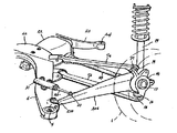
제2도는 제1도의 사시도.2 is a perspective view of FIG.
제3도는 트리이링아암(trailing arm)의 차체쪽아암과 차륜쪽아암과의 사이의 연결상태를 도시한 요부단면도.FIG. 3 is a sectional view of the main part showing the connection state between the body side arm and the wheel side arm of the triiling arm. FIG.
제4도는 각 서스펜션링크(suspension link)의 연결상태를 도시한 사시도.4 is a perspective view showing a connection state of each suspension link.
제5도는 제4도의 평면도.5 is a plan view of FIG.
제6도는 후륜조타용의 작동기를 구동하는 유압회로를 도시한 개략구성도.6 is a schematic configuration diagram showing a hydraulic circuit for driving an actuator for rear wheel steering.
제7도 내지 제9도는 본 발명의 제2의 실시예를 도시한 것으로서, 제7도는 차량의 후륜현가장치의 요부의 개략구성을 도시한 평면도.7 to 9 show a second embodiment of the present invention, and Fig. 7 is a plan view showing a schematic configuration of main parts of a rear wheel suspension of a vehicle.
제8도는 제7도의 사시도.8 is a perspective view of FIG. 7.
제9도는 후륜조타용의 작동기를 구동하는 유합회로를 도시한 개략 구성도.9 is a schematic configuration diagram showing a fusion circuit for driving an actuator for rear wheel steering.
제10도 내지 제13도는 본 발명의 제3의 실시예를 도시한 것으로서, 제10도는 차량의 후륜현가장치의 요부의 개략구성을 도시한 평면도.10 to 13 show a third embodiment of the present invention, and FIG. 10 is a plan view showing a schematic configuration of main parts of a rear wheel suspension of a vehicle.
제11도는 제10도의 II-II선 단면도.11 is a sectional view taken along the line II-II of FIG.
제12도는 부시(81)의 특성도.12 is a characteristic diagram of the bush 81.
제13도는 후륜현가장치의 개략구성을 도시한 모식도.FIG. 13 is a schematic diagram showing a schematic configuration of a rear wheel suspension device. FIG.
제14도는 제3실시예의 변형예를 도시한 제10도의 II-II선 단면도.FIG. 14 is a cross-sectional view taken along the line II-II of FIG. 10 showing a modification of the third embodiment.
제15도 및 제16도는 본 발명의 제4의 실시예를 도시한 것으로서, 제15도는 후륜현가장치의 개략적 평면도.15 and 16 show a fourth embodiment of the present invention, and Fig. 15 is a schematic plan view of a rear wheel suspension.
제16도는 후륜현가장치의 트레이링아암의(trailing arm) 사시도.Figure 16 is a perspective view of the trailing arm of the rear suspension.
제17도 내지 제19도는 본 발명의 제4실시예를 도시한 것으로서, 제17도는 차량의 후륜현가장치의 요부의 개략구성을 도시한 평면도.17 to 19 show a fourth embodiment of the present invention, and FIG. 17 is a plan view showing a schematic configuration of main parts of a rear wheel suspension of a vehicle.
제18도는 제17도의 사시도.18 is a perspective view of FIG. 17;
제19도는 트레이링아암(trailing arm)이 차체에 회동가능하게 연결된 상태를 도시한 요부단면도.Fig. 19 is a sectional view showing the main part of a state in which a trading arm is pivotally connected to a vehicle body.
제20도는 제4실시예의 변형예로서의 트레이링아암이 차체쪽에 원추형으로 접합된 상태를 도시한 요부 단면도.Fig. 20 is a sectional view showing the principal parts of a state in which a tracking arm as a modification of the fourth embodiment is conically joined to the vehicle body side;
* 도면의 주요부분에 대한 부호의 설명* Explanation of symbols for main parts of the drawings
1, 111 : 후륜 4 : 크로스멤버1, 111: rear wheel 4: crossmember
6, 113, 206 : 트레이링아암 7a, 7b, 114, 115 : 레이터럴아암6, 113, 206:
8 : 차체쪽아암 9 : 차륜쪽아암8: body side arm 9: wheel side arm
11 : 회동축 17 ,135 : 보올조인트11:
20, 50a, 50b : 연결봉 31, 61 : 작동기20, 50a, 50b: connecting rod 31, 61: actuator
210 : 부시210: bush
본 발명은, 자동차에 적용되는 후륜조타장치(後輪操舵裝置)에 관한 것으로서, 특히 구조의 개량에 관한 것이다.BACKGROUND OF THE INVENTION 1. Field of the Invention The present invention relates to rear wheel steering apparatuses applied to automobiles, and more particularly to improvement of the structure.
최근 자동차의 선회성능의 향상 혹은 선회반경을 줄이기 위한 목적으로 후륜을 조타하는 장치가 여러가지 제안되고 있다. 후륜조타를 위한 구조로서, 예를들면 일본국 특개소 60-179369호 공보에 기재되어 있는 것과 같이 전륜조타계와 대략 마찬가지의 구성을 후륜쪽에 적용한 것이다. 즉, 이 형식의 것은, 후륜조타용 작동기와, 후륜을 지지하여 차체에 회동가능하게 착설된 너클(knuckle)과, 작동기 및 너클을 연결하여 작동기의 움직임을 너클에 전달하여 연결봉을 착설하여 후륜의 조타를 가능하게 하고 있다.Recently, various devices for steering a rear wheel have been proposed for the purpose of improving the turning performance of a vehicle or reducing the turning radius. As a structure for rear wheel steering, the same structure as that of a front wheel steering system is applied to the rear wheel, as described in, for example, Japanese Patent Laid-Open No. 60-179369. That is, this type of actuator is a rear wheel steering actuator, a knuckle mounted on the vehicle body to support the rear wheels, and the actuator and the knuckle are connected to transmit the movement of the actuator to the knuckle, and the connecting rod is installed to install the rear wheel. Steering is possible.
그러나, 이와 같은 회동 가능한 너클을 사용하는 것에 있어서는 후륜현가장치(後輪懸架裝置)(rear suspension)로서 일반적으로 맥퍼손 스트럿(strut)식 혹은 더불위시보운(double wishbone)식의 것을 사용하지 않으면 안되고, 구조가 복잡해져서 넓은 공간을 필요로 하며, 생산가격이 높아지는 결점이 있다. 또, 서스펜션아암(suspension arm)과 연결봉과의 링크간섭을 피할필요가 있기 때문에 반드시 이상적인 후륜현가장치(rear suspension)의 레이아우트를 취할 수 없는 불편이 있다. 이와 같은 불편을 해소하는 비교적 간소한 구성을 가진 것으로서, 예를들면 일본국 특개소 57-99470호 공보에 기재되어 있는 것이 있다. 이것은 세미트레이링아암(semitrailingarm)식의 후륜현가장치에 있어서, 크로스멤버를(crossmember) 차체에 지지하는 부시(bush)를 작동기에 의해 강제적으로 변형시켜서 크로스멤버 및 세미트레이링아암을 경동(傾動) 시키므로서, 후륜을 조타하는 것이다.However, in the use of such a rotatable knuckle, a rear suspension is generally used as a McPherson strut or double wishbone type. In other words, the complicated structure requires a large space and the production price is high. In addition, since there is a need to avoid link interference between the suspension arm and the connecting rod, there is a inconvenience in that it is not possible to necessarily take an ideal layout of a rear suspension. As a relatively simple structure which eliminates such inconvenience, there is a thing described in Japanese Patent Laid-Open No. 57-99470, for example. This is a semi-trailing arm type rear suspension, which is configured to forcibly deform a bush that supports the crossmember to the body by an actuator to tilt the crossmember and the semi-training arm. By steering the rear wheels.
그러나, 상기 일본국 특개소 57-94170호 공보의 것은 세미트레이링아암식 서스펜션(semitraitrailing arm suspension)을 사용하는 것이기 때문에, 후륜에 작용하는 횡력(橫力)은 서스펜션아암으로 부터 크로스멤버를 통하여 부시에 입력된다. 그리고 후륜조타를 실현시키기 위하여 부시를 부드럽게 설정할 필요가 있기 때문에 작동기의 유압계에 결합이 발생했을 경우, 차량의 선회중에 노면으로 후륜에 입력되는 횡력에 의해, 부시가 크게 변형하여 세미트레이링아암 및 크로스멤버가 경동하여 후륜이 전륜과 역상(逆相)방향으로 조타되는 소위 콤플라이언스(comliance)현상이 크게 발생하기 쉽게, 오우버스티어링(oversteering)이 되어 조타안정성이 악화되는 문제가 있다.However, since Japanese Unexamined Patent Application Publication No. 57-94170 uses a semi-training arm suspension, the lateral force acting on the rear wheel is bushed through the cross member from the suspension arm. Is entered. In order to realize rear wheel steering, it is necessary to set the bush smoothly. When the coupling occurs in the hydraulic system of the actuator, the bush deforms greatly due to the lateral force input to the rear wheel during the turning of the vehicle. There is a problem that the so-called compliance phenomenon in which the rear member is steered in the reverse direction with the front wheel is easily generated due to tilting of the cross member, becomes oversteering and deteriorates steering stability.
이와같이 종래의 것에 있어서는 유압계에 결함이 발생하는 경우에 현수기능이 대폭 악화되는 불편이 있었다.As described above, in the conventional case, when a defect occurs in the hydraulic system, the suspension function is greatly deteriorated.
또, 상기 종래의 것은 후륜현가장치전체를 차체를 차체에 대해서 경동 시키는 것이기 때문에, 작동기로서 비교적 출력이 큰 대형의 것을 필요로 하여 고가로되는 결점이 있다.In addition, since the conventional rear wheel suspension device tilts the vehicle body with respect to the vehicle body, there is a drawback in that the actuator requires a large output with a relatively large output and is expensive.
또한 상기한것은, 후륜에서 멀리 떨어져서 위치하는 부시(bush)를 변형시켜서 후륜을 조타시키는 것이기 때문에, 작동기의 동작량에 대하여 극히 작은 타각(舵角)밖에 얻을 수 없는 결점이 있다.In addition, since the steering of the rear wheels by deforming a bush located far from the rear wheels, there is a drawback that only a very small steering angle can be obtained with respect to the operation amount of the actuator.
본 발명은 상기한 것을 감안하여 창안한 것으로서, 차량의 후부에서 후륜을 지지함과 동시에 전단부가 차체쪽에 원추형으로 접합(회동 가능하게 연결된)되어서 대략 차체전후 방향으로 뻗어있는 트레이링아암과, 외단부를 상기 트레이링아암의 후부에서 자유로이 회전가능하게 연결함과 동시에 내단부를 차체쪽에 원추형으로 접합되어서 대략 차폭방향으로 뻗어 있는 레이터럴아암(lateral arm)을 가지며, 상기 트레이링아암의 앞부분은 대략 차폭 방향으로의 변위를 허용 하도록 착설되어 있는 후륜현가장치를 구비하고, 상기 트레이링아암 앞부분을 대략 차폭방향으로 변위시키도록 상기 트레이링아암을 동작시키므로서 상기 후륜을 조리하는 작동기를 착설한 것을 특징으로 하는 후륜조타장치를 요지로 하는 것이다.SUMMARY OF THE INVENTION The present invention has been made in view of the above, and has a rear arm supporting a rear wheel at the rear of the vehicle, and a front end portion connected to the vehicle body in a conical shape (rotatingly connected) and extending substantially in the front and rear direction of the vehicle body, and an outer end portion. Is freely rotatably connected at the rear of the tracing arm, and has a lateral arm extending in the vehicle width direction by conically joining the inner end to the vehicle body side, wherein the front portion of the tracing arm is approximately the vehicle width direction. And a rear wheel suspension mounted so as to allow displacement in the vehicle, and an actuator for cooking the rear wheels is installed by operating the tracking arm to displace the front portion of the tracking arm in a substantially vehicle width direction. The rear wheel steering gear is the main point.
본 발명에 의하면, 레이터럴아암(lateral arm)은 트레이링아암의 후부에서 후륜을 지지하여 앞부분이 대략 차폭방향으로의 변위를 허용하도록 착설되며, 작동기는 트레이링아암을 동작시켜서 그 앞부부분을 차폭방향으로 변위시키도록 착설되어 있기 때문에, 작동기를 동작시켜서 트리이링아암 부분을 차폭방향으로 변위시키면 트레이링아암은 레이터럴아암과의 연결점을 대략 중심으로 회동하여 후륜이 조타되는 것이다.According to the present invention, a lateral arm is mounted so as to support the rear wheel at the rear of the trailing arm so that the front portion allows displacement in the direction of the vehicle width, and the actuator operates the trailing arm to cover the front portion of the trailing arm. Since it is installed so as to displace in the direction, when the actuator is operated to displace the trimming arm portion in the vehicle width direction, the trailing arm rotates about the connection point with the lateral arm about to steer the rear wheel.
그리고 후분에 후륜을 지지하는 트레이링아암은 그 전단부가 차체쪽에 원추형으로 접합되어서 대략 차체전후 방향으로 뻗어있고, 외단부를 트레이링아암 후부에 연결되는 레이터럴아암은 그 내단부가 차체쪽에 원추형으로 접합되어서 대략 차폭방향으로 뻗는 것으로 되어 있기 때문에 후륜현가장치에 작용하는 전후 방향의 힘은 트레이링아암으로, 또 차폭방향의 힘은 레이터럴아암으로, 각각 분담해서 받는 것으로 되어 있다.And the trailing arm supporting the rear wheel in the rear part has its front end conically joined to the vehicle body and extends in the front and rear direction, and the radial arm connecting the outer end to the rear of the tracking arm has its inner end connected to the car body conical. The force in the front-rear direction acting on the rear wheel suspension is shared with the trailing arm, and the force in the vehicle-width direction is shared with the lateral arms.
그리고 전후 방향의 힘을 받는 트레이리아암의 앞부분은 대략 차폭방향으로의 변위를 허용하도록 착설되어 있으나, 현가장치에 작용하는 차폭방향의 힘은 레이터럴아암이 받기 때문에, 가령 작동기에 결함이 발생하였다고 해도, 그 횡력에 의하여 트레이링아암의 앞부분이 차폭방향으로 변위하는 양은 극히 작으며, 이 결함시에 있어서의 차량선회중에, 전륜과 역상방향으로 후륜이 전타(轉舵) 되는 소위 콤플라이언스 스티어(compliance steer)가 발생하여 오우버스티어링(steerin) 되어 조종안정성을 해치는 종래의 불편을 효과적으로 방지할 수 있는 것이다.In addition, the front part of the trailing arm, which receives the force in the front and rear direction, is installed to allow the displacement in the vehicle width direction. However, since the radial arm receives the force in the vehicle width direction, the actuator has a defect, for example. In addition, the amount of displacement of the front portion of the tracking arm in the vehicle width direction by the lateral force is extremely small, and the so-called compliance steer in which the rear wheels are rotated in the reverse direction to the front wheels during the vehicle turning during this defect. The compliance steer is generated to be steered and can be effectively prevent the conventional inconvenience that impairs the steering stability.
또, 트레이링아암 앞부분은 대략 차폭방향으로의 변위를 허용하도록 착설되어 있기 때문에, 작동기와 트레이링아암과의 연결이 서스펜션 자체의 기하학상의 상하 스트로우크(stroke)에 대하여 간섭하게 되는 경우에 있어서도 트레이링아암의 그 허용되는 변위에 의해 이 링크간섭을 회피할 수 있어, 원활한 서스펜션작동을 얻을 수 있다. 또한 본 발명은 트레이링아암 앞부분을 대략 차폭방향으로 변위시켜서 후륜을 조타하는 것이므로, 세미트레이링아암식 서스펜션의 크로스멤버를 지지하는 부시를 강제적으로 변위시키는 종래의 방식에 비해서 후륜조타에 따른 가동부분을 소형화할 수 있는 동시에 작동기의 작용점을 후륜에 접근시킬 수 있어, 작동기의 동작력을 작게하여 작동기를 소형화 할 수 있는 동시에 큰 조타각을 얻을 수 있는 것이다. 추가해서 트레이링아암과 레이터럴아암을 가진 서스펜션의 트레이링아암 앞부분을 차폭방향으로의 변위가 허용될 수 있도록 착설하여 작동기를 배설하는 것만으로 후륜의 조타가 가능해지기 때문에 종래 보다 더 간소한 구성으로 후륜조타장치를 실현하는 것이다.In addition, since the front part of the tracking arm is installed so as to allow displacement in the direction of the vehicle width, the tray even when the connection between the actuator and the tracking arm interferes with the upper and lower strokes in the geometry of the suspension itself. By the permissible displacement of the ring arm, this link interference can be avoided, and smooth suspension operation can be obtained. In addition, since the present invention is to steer the rear wheel by displacing the front portion of the tracking arm in the vehicle width direction, the movable part according to the rear wheel steering as compared to the conventional method of forcibly displacing the bush supporting the cross member of the semi-training arm suspension. It is possible to reduce the size of the actuator and bring the operating point of the actuator closer to the rear wheel, thereby reducing the operating force of the actuator so that the actuator can be miniaturized and a large steering angle can be obtained. In addition, the front of the tracking arm of the suspension with the tracking arm and the radial arm is installed so that displacement in the vehicle width direction is allowed, so that steering of the rear wheel is possible by simply disposing the actuator. Rear wheel steering is realized.
이하, 본 발명의 실시예를 첨부도면에 의거하여 상세하게 설명한다. 제1도 내지 제6도는 본 발명의 제1실시예를 도시한 것이다. 제1도 및 제2도는 리어서스펜션장치를 포함하는 후륜조타장치의 요부의 개략구성을 도시한 것으로서, (1)은 후륜, (2)는 차체쪽의 프로펠러측, (3)은 몸체프레임, (4)는 서스펜션크로스멤버이다. 이 크로스멤버(4)는 차폭방향으로 설치되어 있으며, 차체의 좌우에 배설된 1쌍의 몸체프레임(3)(3)간에 가설상태로 장착되어 있다. 또한, 이 크로스멤버(4)는 중앙부위쪽이 차체후방쪽으로 만곡된 상태로 굴곡형성되어 있다. 이 경우, 크로스멤버(4)는 탄성체에 의해서 형성된 크로스멤버 부시(bush)(5)를 개재해서 몸체프레일(3)쪽으로 부착되어 있다. 또, (6)은 후단부에 후륜(1) 지지하여 대략 차폭방향으로 뻗어서 부착된 트레이링아암(7a)(7b)는 대략 차폭방향으로 뻗어서 착설된 상하 1쌍의 레이터럴아암이다. 이 트레이링 아암(6)은 차체쪽에 원추형 접합된 차체쪽아암(8)과 후륜(1)을 지지하는 차륜쪽아암(9)으로 분할되어서 구성되어 있다. 이 경우, 차체쪽아암(8)은 차륜쪽아암(9)에 대하여 약간 차폭방향안족에 배치되어 있다. 또, 차륜쪽아암(9)의 전단부에는 제3도에 표시한 바와같이 원통형부(10)가 형성되어 있으며, 이 원통부(10)내에 막대형상으로 형성된 차체쪽아암(8)의 후단부쪽이 삽입되어 있다. 이 차체쪽아암(8)의 전단부쪽은 탄성체에 의해서 형성된 부시(70)를 개재해서 서스펜션크로스멤버(4)에 탄성적으로 원추형으로 접합되어 있다.Hereinafter, embodiments of the present invention will be described in detail with reference to the accompanying drawings. 1 to 6 show a first embodiment of the present invention. 1 and 2 show a schematic configuration of main parts of a rear wheel steering apparatus including a suspension device, (1) the rear wheel, (2) the propeller side of the vehicle body, (3) the body frame, ( 4) is a suspension cross member. The cross member 4 is provided in the vehicle width direction and is installed in a temporary state between a pair of body frames 3 and 3 disposed on the left and right sides of the vehicle body. Moreover, this cross member 4 is bent in the state in which the center part was bent toward the rear of a vehicle body. In this case, the cross member 4 is attached to the body foil 3 via the
또, 차체쪽아암(8)의 후단부쪽과 차륜쪽아암(9)의 원통부(10)와의 사이에는 회동측(11)이 환통상태로 부착되어 있다. 이 회동측(11)은 그 축심방향을 대략 연직선방향을 향해서 배치되어 있으며, 차체쪽아암(8)의 후단부쪽과 차륜쪽아암(9)의 원통부(10)와의 사이에는 회동측(11)을 중심으로 회동가능하게 연결되어 있다. 또, 차륜쪽아암(9)의 원통부(19)와 차체쪽 아암(8)의 후단부 쪽과 차륜쪽아암(9) 원통부(10)와의 사이에는 회동축(11)을 중심으로 회동가능하게 연결되어 있다. 또, 차륜쪽아암(9)의 원통부(10)와 차체쪽아암(8)의 후단부쪽과의 사이에는 탄성체로 형성된 부시(12)가 끼워져있다. 이 부시(12)에는 수평 방향의 양측부에 1쌍의 절결부(12a)(12b)가 형성되어 있으며, 회동축(11)을 중심으로 하는 차륜쪽아암(9)과 차체쪽아암(8)과의 사시의 상대적인 회동동작이 가능하게 되어 있다. 이 때문에 차체쪽아암(8)과 차륜쪽아암(9)로 구성되는 트레일링아암(6)은, 부시(12)(70)를 변형시켜서 발생하는 양 아암(8)(9)의 상대적인 회도에 의해, 앞부분이 차폭방향으로의 변위가 허용되도록 되어 있다.Moreover, the rotating side 11 is attached in the ring state between the rear end part of the vehicle
또, 차륜쪽아암(9)의 후단부에는 대략 원통형상의 액슬 하우징(axlehousin)(13) 및 이 액슬하우징(13)의 외주면에 감착된 허브 캐리어(hub carrier)(14)가 각각 용적등의 수단에 의해서 일체적으로 고착되어 있다. 이 허브캐리어(14)의 상부에는 레이터럴아암의 상부링크(7a)를 지지하는 상부지지부(15)가 형성되어 있는 동시에 (제2도), 허브캐리어(hub housing)(14)의 하부에는 레이터럴 아암의 하부 링크(7b)를 지지하는 하부지지부(16)가 형성되어 있다. 또 레이터럴아암의 상부 링크(7a)의 외단부(外端部)는 이 허브캐리어(14)의 상부지지부(15)에 보올조인트(balljoint)(17)를 개재해서 자유로이 회전할 수 있게 원추형으로 접합되고 상부링크(17a)의 내단부는 차체쪽의 서스펜션크로스멤버에 있어서의 만곡부 선단의 후방돌출부(4a)의 근처부위에 탄성체로 형성된 부시를 개재해서 탄성적으로 원추형접합되어 있다. 또, 레이터럴아암의 하부링크(7b)도 상부링크(7a)와 대략 마찬가지로 외단부가 허브캐리어(14)의 하부지지부(16)에 보올조인트(18)를 통하여 자유로이 회전할 수 있도록 원추형으로 접합되고, 하부링크(7b)의 내단부가 차체쪽의 서스펜션크로스멤버(4)에 있어서의 만곡부선단의 후방돌출부(4a)의 근처부위에 탄성체로 형성된 부시를 개재해서 탄성적으로 원추형 접합되어 있다. 이 때문에 트레이링아암(6)의 후단부는 상하 2개의 레이터럴아암(7a)(7b)을 개재해서 차체에 지지되어 있으며, 트레이링아암(6)의 앞부분과 같이 차폭방향으로의 변위가 허용되는 것으로 되어 있지 않다.At the rear end of the wheel arm 9, a substantially cylindrical axlehousin 13 and a
따라서, 트레이링아암(6)의 앞부분이 차폭방향으로 변위하면 트레이링아암(6)의후부와 레이터럴아암(7a)(7b)과의 원추형 접합점을 중심으로 하여 트레이링아암(6)은 회동하는 것으로 되어 있다. 또, 레이터럴아암(7a)(7b)와 차체쪽의 서스펜션크로스멤버(4)와의 사이의 연결부는, 레이터럴아암(7a)(7b)과 차륜쪽아암(9)쪽과의 연결부 보다도 차체전방쪽으로 배치되어 있다. 그리고, 트레이링아암(6)의 차체쪽아암(8), 차륜쪽아암(9) 및 레이터럴아암(7a)(7b)에 의해서 제4, 제5도에 표시한 바와같은 4절링크가 구성되어 있으며, 차체쪽아암(8)과 차체쪽과의 사이의 제1의 연결부와, 상하의 레이터럴아암(7a)(7b)과 차체쪽과의 사이의 제2의 연결부를 연결하는 차륜지지부으 요동중심선을 중심으로 해서 차륜지지부가 상하방향으로 요동가능하게 지지되어 있다. 또한, 레이터럴아암의 상부 링크(7a)와 차륜쪽아암(9)쪽과의 연결부는 레이터럴아암의 하부링크(7b)와 차륜쪽아암(9)쪽과의 연결부보다도 차체 전방쪽으로 배치되어 있으며, 또한 차량쪽아암(9)의 후단부에는 완충기 브래킷이 형성되어 있으며, 이 완충기브래킥에(bracket) 스트럿(strut)식 완증기(19)의 하단부가 연결되어 있다.Therefore, when the front part of the tracking arm 6 is displaced in the vehicle width direction, the tracking arm 6 pivots about the conical junction between the rear part of the tracking arm 6 and the
한편, 차체쪽아암(8)과 차륜쪽아암(9)과의 사이를 회동가능하게 연결하는 회동축(11)에 연결된 연결봉(20)의 내단부는 크로스멤버(4)에 착설된 후륜조타용의 작동기(31)의 피스톤(33a)에 회동가능하게 연결되어 있다.On the other hand, the inner end of the connecting
또, 연결봉(20)와 트레이링아암(6)의 연결위치는, 제1도에 도시한 바와 같이 차량의 수평면내에서, 트레이링아암(6)의 차체쪽 원추형접합점 중심 C과, 트레이링아암(6)과 상부링크(7a)와의 연결점중심D을 연결하는선 A의 근처에 위치하는 것으로 되어 있으며, 연결봉(20)와 작동기(31)의 연결위치는, 차량의 수평면내에서, 트레이링아암(6)의 차체쪽 원추형접합점중심 C과, 상부링크(7a)의 차체쪽 원추형접합점중심 E을 연결하는선 B상에 위치하는 것으로 되어 있다.In addition, as shown in FIG. 1, the connecting position of the connecting
또, 크로스멤버(4)의 만곡부 선단의 후방돌출부(4a)에는 차동장치(22)가 장착되어 있다. 이 차동장치(22)는 좌우의 보디프레임(body frame)(3)(3)간에 가설상태로 장착된 차동장치지지부재(23)에 의해서 후단부가 지지되어 있다. 또, 이 차동장치지지부재(23)는 탄성체에 의해서 형성된 차동장치지지부재부시(24)를 개재해서 보디프레임(3)쪽에 탄성적으로 연결되어 있다. 또한, (25)는 구동축, (26)은 후륜의 휘일스핀들(sheel spindle)이다.Further, a differential device 22 is attached to the rear projection 4a at the tip of the curved portion of the cross member 4. This differential device 22 is supported at its rear end by a differential support member 23 mounted in a temporary state between the left and right body frames 3 and 3. Moreover, this differential support member 23 is elastically connected to the body frame 3 side via the differential
상기한 후륜조타용의 작동기(31)는 제6도에 도시한 바와같이 유압식의 파우어실린더(32a)(32b)의 피스톤(33a)(33b)에 의해서 형성되어 있으며, 좌우의 후륜(1)(1)쪽에 각각 배설되어 있다. 또, 좌우의 파우어 실린더(power cylinder)(32a)(32b)의 좌실(左室)(34a)(34b)간은 연결관(35)을 개재해서 연통되어 있는 동시에, 좌우의 파우어실린더 (32a)(32b)의 우실(右室)(36a)(36b)간은 연결관(37)을 개재해서 연통되어 있다.The actuator 31 for rear wheel steering is formed by the pistons 33a and 33b of the hydraulic power cylinders 32a and 32b as shown in FIG. They are each excreted on page 1). Further, the left and right chambers 34a and 34b of the right and left power cylinders 32a and 32b are communicated through the connecting pipe 35, and the right and left power cylinders 32a are connected. The right chamber 36a, 36b of 32b is connected through the connecting pipe 37. As shown in FIG.
제6도는 후륜조타용의 작동기(31)(31)를 구동하는 유압회로를 도시한 것으로서, (38)(38)은 전륜, (39)는 파우어스티어링시스템을 갖춘 조타장치, (40)은 스티어링휘일이다. 이 스티어링휘일(40)은 축(41)을 통하여 파우어실린더(42)의 제어밸브(43)에 연결되어 있다.6 shows a hydraulic circuit for driving the actuators 31 and 31 for rear wheel steering, wherein 38 and 38 are front wheels, 39 are steering gears with a power steering system, and 40 are steering. It's a wheel. The
이 제어밸브(43)에는 파우어스티어링용의 펌프(44), 리저어버탱크(45), 파우어실린더(42)의 좌실(46) 및 우실(47)이 각각 연결되어 있다.The
또, 파우어실린더(42)의 좌실(46)과 우실(47)의 사이를 구분하는 피스톤(48)의 피스톤로드(49)의 양단부는 연결봉(50a)(50b)를 개재해서 전륜을 지지하는 너클아암(51a)(51b)에 연결되어 있다. 또, 파우어실린더(42)는 연결관(52a)(52b)을 개재해서 유압절환밸브(53)에 연결되어 있다. 이 경우, 유압절환밸브(53)는 밸브본체(54)와 이 밸브본체(54)내에 축방향으로 자유로이 이동하게 수납되고, 좌우양단부에 힘을 가하는 스프링(55a)(55b)을 갖춘 스푸울(spool)(56)에 의해서 형성되어 있다. 그리고 밸브본체(54)의 좌측에는 밸브좌실(57a), 우측에는 밸브우실(57b)이 각각 형성되어 있으며, 이 유압절환밸브(53)의 밸브좌실(57a)과 파우어실린더(42)의 좌실(46)과의 사이가 연통관(52a)을 개재해서 연결되어 있는 동시에, 유압절환밸브(53)의 밸브우실(57b)과 파우어실린더(42)의 우실(47)과의 사이가 연통관(52b)을 개재해서 연결되어 있다. 또, 스푸울(56)의 중앙부위에는 1쌍의 소경부(小徑部)가 형성되어 있으며, 이들 소경부에 의해서 밸브본체(54)의 내부에 제1의 밸브실(58a) 및 제2의 밸브실(58b)이 각각 형성되어 있다. 그리고, 제1의 밸브실(58a)에는 제1포오트(59a), 제2포오트(59b) 및 제3포오트(59c)가 각각 형성되어 있는 동시에, 제2의 밸브실(58b)에는 제4포오트(59d), 제5포오트(59e) 및 제6포오트(59f)가 각각 형성되어 있다. 제1포오트(59a) 및 제5포오트(59e)는 리저어버탱크(45)에 연결되어 있는 동시에, 제2포오트(59b) 및 제4포오트(59d)는 후륜조타용의 펌프(60)에 연결되어 있다. 이 펌프(60)는 도시하지 않는 변속기의 출력축으로 부터 구동력을 받아서 차속도에 대응하는 유량의 작동유를 토출하는 차속비례펌프에 의해서 형성되어 있다. 또, 제3포오트(59c)는 연결관(37)에 연결되어 있는 동시에, 제6포오트(59f)는 연결관(35)에 연결되어 있다.In addition, both ends of the
상기와 같은 구성을 가진 상기 제1실시예의 작용에 대해서 이하에 설명한다.The operation of the first embodiment having the above configuration will be described below.
먼저, 후륜의 조타작용에 대해서 설명하면, 차량의 직진주행시에는 스티어링휘일(40)은 중립상태로 유지되어 있으므로, 전륜은 제6도중에 실선으로 표시한 바와같이 직진상태로 유지되어 있다. 이 상태에서는 후륜 조타용의 작동기(31)의 양 압력실에 작용하는 등압으로 되어, 피스톤(33a)(33b)은 파우어실린더(32a)(32b)내의 중립위치에서 유지되어 있으며, 후륜은 제6도중에 실선으로 표시한 바와 같이 직전 상태로 유지되어 있다. 또, 비교적 고속상태로 주행중의 차량을 예를들면 제6도중에서 좌즉으로 선회시킬 경우에는 스티어링휘일(40)의 조타동작에 연동해서 파우어실린더(42)의 제어밸브(43)가 구동되어서 파우어실린더(42)내의 피스톤(48)이 제6도중에서 오른쪽 방향으로 이동한다. 또, 이 피스톤(48)의 이동에 따라서 피스톤로드(49)의 양단부에 연결된 타이로드(50a)(50b)를 개재해서 너클아암(51a)(51b)이 좌선회해서 전륜(38)이 제6도중에 점선으로 표시한 바와같이 왼쪽방향으로 조타되도록 되어 있다. 또, 이 파우어실린더(42)의 피스톤(48)의 이동동작에 따라 파우어실린더(42)의 좌실(46)내의 고압상태의 작동유의 일부가 연통관(52a)을 개재해서 유압절환밸브(53)의 밸브좌실(57a) 내로 파일럿(pilot) 신호압력으로서 도입된다.First, the steering operation of the rear wheels will be described. Since the
그 때문에, 유압절환밸브(53)내의 스푸울(56)이 제6도중에서 오른쪽 방향으로 이동하여, 제1포오트(59a) 및 제4포오트(59d)가 각각 폐쇄되므로, 후륜조타용의 펌프(60)로 부터 토출된 작동유는 제2포오트(59b)를 개재해서 제1의 밸브실(58a)내로 도입되며, 또 이 제1의 밸브실(58a)로 부터 제3포오트(59c), 연결관(37)을 개재해서 좌우의 파우어실린더(32a)(32b)의 우실(36a)(36b)내에 각각 도입되도록 되어 있다. 따라서, 좌우의 파우어실린더(32a)(32b)내의 피스톤(33a)(33b)이 각각 제6도중에서 왼쪽방향으로 이동하므로, 타이로드(20)(20)를 개재해서 트레이링아암(6)의 앞부분에 위치하는 회동축(11)이 왼쪽방향으로 이동조작되며, 이회동축(11)을 중심으로 하여 차체쪽아암(8)과 차륜쪽아암(9)의 사이가 상대적으로 회동하고, 이 차륜쪽아암(9)의 회동동작에 따라서 후륜(1)이 제6도중에 점선으로 표시한 바와같이 전륜과 같은 모양쪽인 왼쪽방향으로 조타되어서 차량의 후륜이 조타되도록 되어 있다.Therefore, the sprue 56 in the hydraulic switching valve 53 moves in the right direction in the sixth degree, and the first port 59a and the fourth port 59d are closed, respectively. The hydraulic oil discharged from the pump 60 is introduced into the first valve chamber 58a via the second port 59b and from the first valve chamber 58a to the third port 59c. And through the connection pipe 37, respectively, are introduced into the right chambers 36a and 36b of the right and left power cylinders 32a and 32b. Therefore, the pistons 33a and 33b in the left and right powder cylinders 32a and 32b respectively move in the left direction in the sixth degree, so that the tracking arm 6 is moved through the
이 경우, 파우어실린더(32a)(32b)의 좌실(34a)(34b)내의 작동유는 연결관(35), 제6포오트(59f), 제2의 밸브실(58b), 제5포오트(59e)를 순차적으로 개재해서 리저어버탱크(45)내로 복귀되도록 되어 있다.In this case, the hydraulic oil in the left chambers 34a and 34b of the powder cylinders 32a and 32b is connected to the connection pipe 35, the sixth pot 59f, the second valve chamber 58b and the fifth pot ( 59e) is sequentially returned to the reservoir tank 45.
또, 비교적 고속상태로 주행중의 차량을 제6도중에서 우측으로 선회시킬 경우에도 대략 마찬가지의 동작에 의해서 후륜이 전륜과 동일방향으로 조리되도록 되어 있다.Further, even when the vehicle that is traveling at a relatively high speed is turned to the right in FIG. 6, the rear wheels are cooked in the same direction as the front wheels by the substantially same operation.
또한, 차량의 주행속도가 비교적 낮은 경우에는 후륜조타용의 펌프(60)의 토출유압이 낮기 때문에, 작동기(31)가 후륜을 조타할만한 힘을 발휘할 수 없어, 후륜은 조타될 수 없는 것으로 되어 있다. 그런데, 상기 구성의 서스펜션은, 트레이링아암(6)의 차체쪽아암(8), 차륜쪽아암(9) 및 레이터럴아암(7a)(7b)에 의해서 제5도에 도시한 바와같이 수평면내에서의 4마디의 링크가 구성되어 차체쪽아암(8)과 차륜쪽아암(9)의 사이를 연결하는 회동축(11)을 중심으로 하는 차륜쪽아암(9)과 차체쪽아암(8)의 사이의 상대적인 회동동작에 따라서 후륜의 스핀들(26)의 위치를 이동시켜서 후륜의 토우변화를 행하게 할 수 있는 것으로 되어 있다. 그리고 이 4마디의 링크의 작용에 의해 트레이링아암(6)의 앞부분만이 차폭방향으로 변위가능하게 되어 후륜의 타각 혹은 토우각의 변화가 가능하게 되어, 후륜의 타각 혹은 토우각의 변화가 능하게되어 있다. 이때문에 상기와 같은 후륜의 조타가 가능할 뿐만아니라 직진시, 저속시등의 후륜의 조타가 행해지지 않는 상태에 있어서, 예를들면 차량제동시와 같이 차체에 후방향의 힘이 작용했을 경우에는 이 후방향의 힘에 의해서 차륜쪽아암(9)고 차체쪽아암(8)과의 사이에서 회동축(11)을 중심으로 하는 상대적인 회동동작을 행하게 하여, 이 회동동작에 따라서 상기 4마디링크를 통상위치로 부터 제5도에 2점쇄선으로 표시한 토우잉 위치까지 변형시켜서 후륜의 토우변화를 행하게 할 수 있다.In addition, when the running speed of the vehicle is relatively low, since the discharge oil pressure of the pump 60 for rear wheel steering is low, the actuator 31 cannot exert a force sufficient to steer the rear wheel, and the rear wheel cannot be steered. . By the way, the suspension of the said structure is as shown in FIG. 5 by the
또, 상기의 서스펜션은 트레이링아암의 후부를 지지하며서 차폭방향으로 뻗는 레이터럴아암을 가지고 있기 때문에, 일반적으로 차량선회시에 후륜에 작용하는 횡력에 의해 발생하는 콤플라이언스 스티어는 적고 조작안성성에 뛰어난 것으로 되어 있다. 또 상기 서스펜션은 레이터럴아암(7a)(7b)과 차체쪽의 크로스멤버(4)와의 사이의 연결부를 레이터럴아암(7a)(7b)과 차체쪼아암(9)쪽과의 연결부 보다도 차체전방쪽으로 배치하였으므로, 트레이링아암(6)의 차체쪽아암(8)의 중심선과 레이터럴아암의 중심선(상부링크(7a)의 중심선과 하부링부(7b)의 중심선광의 상이의 중심선)과의 교차점에 의해서 형성되는 서스펜션아암의 순간중심이 0이 차축의 차체 바깥쪽이고 후방쪽에 설정된다.In addition, since the suspension has a rear arm extending in the vehicle width direction while supporting the rear portion of the trailing arm, in general, there is little compliance steer generated by the lateral force acting on the rear wheel during the turning of the vehicle and excellent in operation stability. It is supposed to be. In addition, the suspension is connected between the
그때문에, 후륜조타용의 작동기(31)의 작동을 제어하는 유압계에 결함이 발생하여도, 차량의 선회시에는, 선회바깥쪽으로 부터 후륜에 작용하는 횡력에 의해서 차륜쪽아암(9)과 차체쪽아암(8)의 사이에서 회동축(11)을 중심으로 하는 상대적인 회동 동작을 행하게 하여, 이 회동 동작에 따라서, 4마디링크를 변형시켜서 외륜쪽의 후륜에 토우인(toe-in)작동, 내륜쪽의 후륜에 토우아우트(toe-out)작동을 각각 줄수 있다. 이 작용과 상기한 레이터럴아암에 의한 콤플라이언스 스티어의 억제작용에 의해, 작동기(31)으 유압계에 결합이 발생하여도 차체의 선회동작시에 확실하게 차량의 오우버스티어현상을 방지할수 있다. 또한, 이 경우에 얻어지는 후륜의 토우각변화량은, 상기한 작동기(31)의 작동에 의해 얻어지는 후륜 조타각보다는 작은 것으로 되어 있는 것을 말할 것도 없다.Therefore, even if a fault occurs in the hydraulic system that controls the operation of the actuator 31 for rear wheel steering, the wheel arm 9 and the vehicle body at the time of turning the vehicle by the lateral force acting on the rear wheel from the outside of the turning. Relative to the rotational axis centering on the rotational shaft 11 is performed between the
또, 연결봉(20)는, 차량의 수평면내에서 트레이링아암(6)쪽의 연결부가 제1도중의 선A상 근처에, 작동기(31)쪽의 연결부가 제1도중의선 B상에 각각 배치되어 있기 때문에, 서스펜션의 상하스트로우크에 즈음하여 연결봉(20)와의 사이에서 링크간섭이 발생하는 것을 유효하게 방지할 수 있고, 연결봉(20)의 영향으로 서스펜션의 상하스트로우크에 토우각이 변화하는 것을 방지할 수 있는 것이다. 추가해서, 상기와 같은 연결봉(20)의 배치를 취하지 않는 경우에 있어서도, 트레이링아암(6)의 앞부분은 차폭방향으로의 변위자유도를 가지기때문에, 그 변위에 의해 상기한 링크간섭을 흡수할 수 있는 것이다. 그리고, 이 경우는 차량주행중의 상하 동작에 따라서 서스펜션장치전체가 상하동작해서 차체가 통상위치로 부터 상하방향으로 이동하고, 트레이링아암(6)의 차체쪽연결부와 상하 1쌍의 각 레이터럴아암(7a)(7b)의 차체쪽 연결부와의 사이를 연결하는 차륜지지부의 요동중심선을 중심으로 차륜지지부가 상하로 요동할때에 차체쪽아암(8)과 차륜쪽아암(9)과의 상대적인 회동동작을 연결봉(20)에의해서 억제할 수 있으므로, 차체의 상하방향의 이동동작에 따른 후륜(1)의 토우변화를 억제할 수 있다.In addition, in the horizontal plane of the vehicle, the connecting
또, 상기 서스펜션은 레이터럴아암(7a)(7b)과 차체쪽의 크로스멤버(4)와의 사이의 연결부를 레이터럴아암(7a)(7b)과 트레이링아암(6)쪽과의 연결부 보다도 차체전방쪽으로 배치하고, 레이터럴아암(7a)(7b)을 차폭방향에 대해서 경사지게 배치하고, 또 크로스멤버(4)에 작동기(31)를 배설하였으므로, 후륜조타장치를 포함하는 리어서스펜션장치 전체의 소형화를 도모할 수 있다.In addition, the suspension has a connection portion between the
또한, 트레이링아암(6)의 전단부쪽을 부시를 개재해서 크로스멤버(4)에 탄성적으로 원추형으로 접합시키고, 또한 레이터럴아암(7a)(7b)의 내단부를 크로스멤버(4)에서의 만곡부선단의 후방돌출부(4a)의 근처부위에 부시를 개재해서 탕성적으로 원투형접합시키고, 또 크로스멤버(4)에 작동기(31)를 장착하였으므로, 크로스멤버(4)를 보디프레임(3)쪽에 부착하기 전에 이 크로스멤버(4)에 리어서스펜션장치 및 후륜조차용의 작동기를 장착할 수 있다. 그때문에, 차체의 조립작업의 작업성향상을 도모할 수 있다. 또, 이 크로스멤버(4)의 중앙부 위쪽을 차체후 방쪽으로 만곡시켰으므로, 크로스멤버(4)에서의 만곡선단의 후방돌추부(4a)에 차동장치(22)를 장착할 수 잇으며, 이 경우 그 작업성의 향상을 도모할 수도 있다.In addition, the front end portion of the tracking arm 6 is elastically conical joined to the cross member 4 via a bush, and the inner end of the
상기 제1실시예에 의하면, 상술한 바와같이 대략 차체전후방향으로 뻗는 트레이링아암(6)이 차체쪽아암(8)과 차륜쪽아암(9)으로 분할되어서 구성되고, 트레이링아암(6)의 후부가 대략 차폭방향으로 뻗는 2개의 레이터럴아암(7a)(7b)에 의해 차체쪽지지되는 것으로 했기 때문에, 서스펜션자체에 콤플라이언스 스티어의 억제작용과 오우버스티어를 방지하는 작용을 가지게 하는 동시에 억제력에 대한 토우인작용을 가지게 하면서, 트레이링아암(6) 앞부분의 차폭방향으로의 변위가 허용되는 구성이 실현되어 있다. 이때문에 이 서스펜스에 타이로드(20)와 작동기(31)를 장착하는 것만으로 후륜의 조타가 가능하며 극히 간소한 구성으로 후륜 조타장치를 실현할 수 있는 효과가 있다.According to the first embodiment, as described above, the tracking arm 6 extending substantially in the front and rear direction of the vehicle body is divided into the
또, 서스펜션자체가 상술한 바와같은 호적한 작용을 가지고 있는 것이기 때문에, 가령작동기(31) 혹은 유압계 유압의 공급이 중단되어도 과대한 오우버스티어등이 발생해서 주행안정성을 현저하게 손상시키는 불편을 유효하게 방지할 수 있는 것이며, 특히 안정성에 뛰어난 효과가 있다. 또한, 상술한 서스펜션을 사용하므로서, 타이로드(20), 작동기(31) 및 유압계의 장착을 선택하는 것만으로, 후륜조타장치를 가진 차량과 가지고 있지 않는 차량과의 사양설정(仕樣設定)을 행할 수 있어, 사양이 다른 차량의 생성에 뛰어난 것이다.In addition, since the suspension itself has the proper function as described above, even if the supply of the actuator 31 or the hydraulic pressure of the hydraulic system is interrupted, an excessive overstress or the like occurs and the inconvenience of significantly impairing the running stability is eliminated. It can prevent effectively, and it is especially excellent in stability. In addition, by using the suspension described above, simply selecting mounting of the
추가해서, 상기 제1실시예에 의하면, 후부에 후륜(1)이 저지되는 트레이링아암(6)의 차륜쪽아암(9)의 앞부분을 작동기(31)에 의해 직접차폭방향으로 변위시켜서 후륜(1)을 조타시키는 것이고, 또, 차륜쪽아암(9)은 후부를 레이터럴아암(7a)(7b)에 의해 보올조인트를 개재해서 지지되는 것이기 때문에, 종래에 비해서 작동기의 작동량에 대한 후륜의 타각을 크게 얻을 수 있는 동시에, 작동기(31)의 작동력을 경감시켜서 작동기 및 유압계의 소형화를 실현할 수 있는 효과가 있다. 그리고 특히 작동기(31)는 연결봉(20)를 개재해서 트레이링아암(6)의 각 아암(8)(9)의 연결점부근을 변위시키는 것이기 때문에, 작동기(31)의 동작에 대한 후륜의 전타의 응답이 신속하고, 드라이버빌리티(driveability)에 뛰어난 효과가 있다. 또, 연결봉(20)의 양단부의 연결부가, 수평면에서, 각가 트레이링아암(6)의 차체쪽 원추형접합부와 레이터럴아암(7a)(7b)의 트레이링아암족 연결부 및 차체쪽 연결부를 연결하는 각선 A, B상 근처에 위치시키므로서 레이터럴링크(7a)(7b)와 연결봉(20)와의 링크간섭을 방지시키고 있기 때문에, 원활한 서스펜션스트로우크(Suspension stroke)를 얻을수 있는 동시에, 후륜의 타각을 적정하게 제어할 수 있는 효과가 있다. 추가해서, 각 서스펜션아암(6)(7a)(7b) 및 작동기(31)가 크로스멤버에 고정되는 것으로 되어있기 때문에, 서스펜션을 포함한 후륜조타장치를 소형이고 또한 조립작업성에 뛰어난 것을 제공하는 효과가 있다.In addition, according to the first embodiment, the rear wheel (1) is displaced in the direct vehicle width direction by the actuator (31) by directly displacing the front portion of the wheel arm (9) of the trailing arm (6) on which the rear wheel (1) is blocked. 1), and since the rear arm 9 is supported by the rear arm by the
제7도 내지 제9도는 본 발명의 제2의 실시예를 도시한 것으로서, 상기 제1실시예와 실질적으로 공통하는 부재에는 동일한 부호를 붙이고, 그 상세한 설명은 생략하여 이하에 설명한다.7 to 9 show a second embodiment of the present invention, in which members substantially the same as those of the first embodiment are denoted by the same reference numerals, and detailed description thereof will be omitted below.
본 실시예는, 후륜조타용의 작동기(61)를 유압실린더의 피스톤(62)에 의하여 형성하고, 또한 좌우의 각 후륜을 각각 구동하는 피스톤로드(63)(64)를 일체적으로 연결한 것이다. 이 경우, 피스톤로드(63)(64)의 각 내단부는 피스톤(62)에 고착되어 있는 동시에, 각 외단부는 좌우의 연결봉(20)(20)의 각 내단부에 각각 회동 가능하게 연결되어 있다. 또, 좌우의 연결봉(20)(20)의 각 외단부는 브래킷(65) 및 보올조인트(75)를 개재해서 회동축(11)근처의 차륜쪽아암(9)의 바깥면에 연결되어 있다. 또, 후륜조타용의 펌프(76)는 차동장치(22)에 부착되고, 차동장치(22)내의 치차로부터, 구동력을 받아, 차속도에 비례한 유량의 작동유를 토출하는 것으로 되어 있다. 그리고 펌프(76)의 근처에는 후륜조타계 전용의 리저어버탱크(77)가 착설되어 있다. 도 유압절환밸브(53)는 제1실시예의 경우와 마찬가지로 구성되어 있으나, 유압원으로 되는 펌프(76)가 차동장치(22)에 부착됨에 따라 차량의 후부에 배치되는 것으로 되어있다.In this embodiment, the
상기 구성에 의하면, 좌우의 각 후륜을 각각 구동하는 작동기(61)가 단일의 유압실린더의 피스톤(62)에 의하여 형성되어 있으므로, 1쌍의 유압실린더를 사용하는 경우에 비해서 코스트저하를 도모할 수 있다. 또, 후륜에 노면측으로 부터 외력이 작용했을 경우에 1쌍의 유압실린더를 사용하는 경우와 같이 좌우의 각 유압실린더내의 작동유의 기름누설, 혹은 작동유의 압축등에 의하여 좌우의 각 후륜이 각각 별개로 동작(토우변화)하는 일이 없으며, 동작의 안정성을 높일 수 있다. 또, 후륜조타용펌프(76)가 차동장치(22)에 착설되었기 때문에, 펌프(76)와 작동기(61)의 거리가 짧아져서, 유압배관의 길이를 단축하여, 배관스페이스의 축소화, 코스트의 저하, 아별ㄱ손실의 저감, 안전성의 향상을 동시에 실현할 수 있다.According to the above configuration, since the
상기한 바와 같이 제2실시예에 의하면, 제1실시예와 마찬가지의 효과를 얻을 수 잇는 동시에 제1실시예에 비하여 값싸고 또한 작동안정성이 뛰어나고, 스페이스효율 및 안정성을 향상시키고 압력손실을 저감시키는 효과가 있다.As described above, according to the second embodiment, the same effects as those of the first embodiment can be obtained, and they are cheaper and more excellent in operational stability than the first embodiment, improving space efficiency and stability, and reducing pressure loss. It works.
제10도∼제13도는 본 발명의 제3실시예를 도시한 것으로서, 상기 제1, 제2실시예와 실질적으로 공통되는 부재에는 동일한 부호를 붙이고, 그 상세한 설명은 생략하여 이하에 설명을 한다.10 to 13 show a third embodiment of the present invention, in which members substantially the same as those of the first and second embodiments are given the same reference numerals, and detailed descriptions thereof will be omitted below. .
차체쪽아암(9)의 회동축(11)의 근처에 착설된 브래킷(65)에는 연결봉(20)의 외단부가 부시(81)를 개재해서 원추형 접합되어 있다. 연결봉(20)는 그 축선이 차폭방향으로 배치되어 있으며, 연결봉(20)의 중심축선의 연장선과 레이터럴아암의 중심선의 연장선과의 교차점 Q은후륜중심보다 차폭방향 안쪽으로 위치하는 것으로 되어있다. 또 연결봉(20)의 내단부는 후륜조타용 작동기(61)의 피스톤로드(63)에 보올조인트를 개재해서 연결되어 있다. 또 작동기(61)는 제2실시예와 마찬가지로 피스톤로드(63)를 도시하지 않는 후륜쪽에 연결되는 피스톤로드(64)와 일체적으로 동작시키는 것으로 되어 있다. 그런데 연결봉(20)와 차륜아암(9)의 사이에 끼워지는 부시(81)는 제11도에 도시한 바와 같은 구조로되어 있다. 부시(81)는 연결봉(20)의 외단부에 형성된 외통부(外筒部)(82)을 겉으로 끼우는 동시에 연결봉(20)에 연결되는 추축(樞軸)(86)을 삽통하는 내통칼라(83)를 안구멍에 끼운 형태로 연결봉(20)에 착설되어 있다. 그리고 부시(81)의 차폭방향안쪽에 위치하는 부분은 살의 일부가 절결된 공동(空洞)형상의 홈(84)이 형성되어 있으며, 부시(81)의 차폭방향 바깥쪽으로 위치하는 공동형상의 홈부분에는 금속제의 스티일인서어트(steel insert)(85)가 끼워져 있다. 이때문에 부시(81)는 추축(86)에 작용하는 차체안쪽방향으로의 힘에 대해서는 탄성이 높은 것으로 되어 있다. 즉, 부시(81)가 받는 하중과 변형량의 특성은 제12도에 도시한 바와같이 되어 있다. 이 때문에, 부시(81)는 트레이링아암(6)의 회동축(11)부근의 차폭방향 안쪽으로의 변위는 허용하고, 차폭방향 바깥쪽으로의 변위는 규제하는 것으로 되어 있다. 한편, 차체쪽아암(8)과 크로스메머(4)와의 사이에 개장된 부시(81)는, 그 탄성이 부시(81)의 홈(84)쪽의 탄성보다는 높고, 부시(81)의 스티일인서어트(85)쪽의 탄성보다는 낮은 것으로 되게 설정되고, 또한 트레이링아암(60)의 회동축(11)부근이 차체쪽아암(8)의 축선방향 차체쪽으로 변위하는 것을 허용할 수 있는 탄성으로 설정되어 있다. 또 레이터럴아암(7a)(7b)과 크로스멤버(4)와의 사이에 끼워져있는 부시(80)는 부시(70)보다 충분히 탄성이 높은 것으로 되어 있다. 상기 제3실시예의 서스펜션 구성은 제13도에 도시한 개략도와 같이 표시된다. 또, 작동기(61)의 작동을 제어하는 유압계의 구성은 제6도 혹은 제9도에 도시한 것이 사용된다. 상기 구성에 의한 작용을 이하에 설명한다.The outer end of the connecting
후륜에 제동력 Br 혹은 횡력 F이 작용했을 경우에는 제1실시예와 마찬가지로, 순간중심점(0)주위의 모우먼트의 작용에 의해 트레이링아암(6)의 회동축(11)부근이 차폭방향 안쪽으로 변위하여, 후륜은 토우인 작동한다. 그리고, 이때 트레이링아암(6)의 회동축(11)부근의 차체안쪽으로의 변위는 부시(81)의 홈(84)쪽으로의 변형에 의해 흡수되는 것이기 때문에, 연결봉(20)에 의해 상기한 바와 같이 후륜(1)의 토우인 동작이 방해되는 일은 없으며, 상술한 바와같이 제1실시예와 마찬가지로 제동력 Br 혹은 횡력 F에 대하여 후륜의 토우인작동을 행할 수 있다. 또, 차량의 발진가속시, 후륜에 구동력에 의한 앞방향의 힘 T이 작용하면, 순간중심점(0)주위의 모우면트의 작용에 의해 트레이링아암(6)의 회동축(11)부근을 차폭방향을 바깥쪽으로 변위시켜서 후륜이 토우아우트작동할려고 하나, 트레이링아암(6)의 회동축(11)부근은 연결봉(20)에 의해 작동기(61)를 개재해서 차체쪽과 연결되어 있고, 부시(81)는 스티일인서어트(85)에 의해 회동축(11)부근의 차체바깥쪽으로의 변위를 규제하는 것으로서 작용하기 때문에, 후륜(1)의 토우아우트는 방해된다. 그리고 이때의 순간중심점(0)주위의 모우먼트의 작용에 의해 후륜을 토우아우트작동시킬려고 하는 힘의 반력이 연결봉(20)에 강하게 작용하여 연결봉(20)는 인장력을 받는다. 이 때문에 연결봉(20)는 후륜의 동작을 제어하는 서스펜션아암의 하나로서의 기능을 발휘하게 되어 연결봉(20)의 연장선과 레이터럴아암의 중심선과의 교차점Q이 의삭적(擬似的)인 순간중심점으로서 작용하게 된다. 그리고 이 교차점 Q은 후륜중심보다 차폭방향 안쪽으로 위치하는 것으로 되어 있기 때문에, 이 의사적인 순간중심점 Q주위의 모우먼트의 작용에 의해 후륜은 토우인작동한다. 그리고 이때 트레이링아암(6)의 회동축(11)부근의 차체쪽아암(8)축 선방향으로의 변위는 부시(7)의 변형에 의해 흡수되기 때문에, 차체쪽아암(8)의 존재에 의해 상기한 바와 같은 토우인작동이 저해되는 일이 없으며, 차체쪽아암(8)과 연결봉(20)와의 사이에서 링크간섭이 발생하는 일도 없다. 또, 작동기(61)를 작동시켜서, 피스톤로드(63)(64)를 차폭방향으로 변위시키면, 연결봉(20)가 차체쪽아암(9)의 앞부분을 차폭방향으로 변위시키기 때문에, 제1 및 제2실시예와 마찬가지로 차체쪽아암(9)이 경동해서 후륜(1)이 조타되는 것이다. 그리고 작동기(61)의 작동에 의해 얻어지는 후륜의 타각은 상기한 토우인작동량에 비햐서 충분히 크며, 부시(81)의 존재에 관계없이 신속한 응답성을 가지고 후륜이 조타되도록 작동기(61)의 스트로우크가 설정되어 있다.When the braking force Br or the lateral force F acts on the rear wheel, similarly to the first embodiment, the rotational shaft 11 of the tracking arm 6 is moved inward in the vehicle width direction by the action of the momental motion around the instantaneous center point (0). Displaced, the rear wheels operate in a toe. At this time, since the displacement of the tracking arm 6 near the rotational shaft 11 into the vehicle body is absorbed by the deformation of the bush 81 toward the
상기한 제3실시예에 의하면 작동기(61)의 동작에 의해 후륜을 조타할 뿐만아니라, 후륜에 제동력 Br이나 횡력F이 작용햇을때와 구동력 T이 작용했을때에 서스펜션동작의 순간중심점을 바꾸어서 작동기(61)의 동작에 의지함이 없이 양쪽의 경우에 대해서 효과적으로 후륜을 토우인작동시킬 수 있어, 차량의 주행안전성을 보다 향샹시키는 효과가 있다. 또, 제1 및 제2실시예와 마찬가지의 효과를 얻을 수 있는 것은 말할것도 없다. 또한 상기 제3실시예의 부시(81)대신에 제14도에 도시한 바와 같은 긴구멍통형상의 내통(內筒)칼라(93)를 끼운 부시(91)를 사용하는 것으로해도 된다. 이 경우는 서스펜션의 통상시에는 트레이링아암(6)쪽에 착설되는 추축(86)을 내통칼라(93)의 차폭방향 바깥쪽으로 위치시켜서 차폭방향 안쪽에 초기클리어런스 S를 가지게 하므로서, 이 초기 클리어런스 S에 의해 트레이링아암(6)의 회동축(11)부근의 차체안쪽으로의 변위만이 허용되는 것으로 해둘 필요가 있다.According to the third embodiment, not only the rear wheel is steered by the operation of the
제15도 및 제16도는 본 발명의 제4실시예를 도시한 것이다. 각 도면은 후륜조타장치를 포함하는 리어서스펜션구조를 모식적으로 도시한 것으로서, (111)은 후륜이며, 허브캐리어(112)에 장착되어 있다. 허브캐리어(112)는 대략 차체전후 방향으로 뻗는 트레이링아암(113)의 후단부에 지지고정되어 있다. 트레이링아암(113)은 후륜(11)자축의 후방에 있어서, 대략 차폭방향으로 뻗는 상하 2개의 레이터럴아암(114)(115)(한쪽만을 도시)에 보올조인트(135)를 개제해서 지지되어 있다. 그리고, 레이터럴아암(114)(115)의 내단부는 부시(116)를 개재해서 차체(117)에 자유로이 회동하도록 하게 원추형 접합되어 있다. 또, 트레이링아암(113)은 차체쪽아암(118)의 일단부에는 환상부(環狀部)(120)를 가지고 있으며, 이 환상부(120)의 내부에는 부시(121)가 착설되어 있다. 즉 차체쪽아암(118)은 이 부시(121)를 개재해서 차체(117)에 지지되어 있으며, 이 부시(121) 는 내향력(內向力) a에 대해서는 스프링정수(正數)가 작게, 외향력 b에 대해서는 스프링정수가 크게 형성되어 있다. 또, 이부시(121)의 지축(122)은 상단부가 차체(117)의 바깥쪽으로 향하도록 경사져 있는 동시에, 내향력 a에 대해서는 이동가능하고, 외향력 b에 대해서는 충지부(衝止部)(123)에 의해서 이동이 규제되도록 부착되어 있다. 이에 의해서 서스펜션의 신장쪽스트로우크시, 즉 하향력 C에는 상기 환상부(120)가 안쪽으로 이동하여 후륜(111)이 토우인 작동하나, 압축쪽스트로우크시, 즉 상향력 d에는 환상부(120)가 충지부(123)에 당접하여 토우아우트로 되지 않도록 규제하고 있다. 차체(117)에 일단부가 지지된 차체쪽아암(118)의 타단부에는 연직방향을 축심으로 하는 추지축(124)에 의해서 상기 차륜쪽아암(119)이 회동 가능하게 연결되어 있다. 그리고, 이 차체쪽아암(118)과 차륜쪽아암(119)이 수평면내에서 이루는 각도가차체(117) 안쪽방향쪽에서 둔각(90˚이상)이 되게 배치되어 있다. 또, 양 아암(118)(119)의 추착부(125)에 있어서의 안쪽은 부시(126)를 개재해서 차체(117)에 지지되어 있다. 그리고, 트레이링아암(113)의 후단은 ㄹ보올조인트(135)를 개재해서 레이터럴아암(114)(115)에 지지되어 있기 때문에, 부시(121)(126)의 탄성변형 및 차체쪽아암(119)과 차륜쪽아암과의 상대회전에 의해 트레이링아암(113)의 앞부분은 대략 차폭방향으로 변위가 허용되는 것으로 되어 있다.15 and 16 show a fourth embodiment of the present invention. Each figure schematically shows a suspension structure including a rear wheel steering device, where 111 is a rear wheel and is mounted on the
또 추착부(125)의 바깥쪽에 있어서의 차체(117)에는 상기각도가 감소하는 방향으로의 차륜쪽아암(119)의 움직임을 규제하는 스토퍼(127)가 착설되어 있다. 즉, 이 스토퍼(127)는 파우어스티어링기구(128)와 유압회로(129)를 개재해서 연통하고, 유압에 의해서 출몰하는 후륜조타용작동기(130)에 의해서 돌출위치를 조절할 수 있도록 되어 있다. 또한, 작동기(130) 및 리어서스펜션장치는 제15도중 왼쪽의 것만이 도시되어 있으나, 당연히, 좌웅대칭으로 착설되어 있다. 또, 파우어스티어링기구(128)와 작동기(130)의 사이에는 도시하지 않는 절환밸부기구가 배설되어 있으며, 저차속시는 선회내륜쪽의 작동기에 유압이 작용하고, 고차속시에는 선회외륜쪽의 작동기에 유압이 작용하는 것으로 되어 있다.Further, a stopper 127 is installed on the vehicle body 117 on the outside of the
상기 제4실시예의 작용에 대해서 이하에 설명한다. 스토퍼(127)는 파우어스티어링기구(128)로부터 유압회로(129)를 개재해서 후륜조타용작동기(130)로 공급되는 유압에 의해서 돌출량이 제어되는 것으로 되어 있기 때문에, 전륜의 조타에 따른 작동기(130)의 작동에 의해 스토퍼(127)가 돌출하면 차륜쪽아암(119)과 차체쪽아암(118)과의 이루는 각도가 증대해서 부시(121)(126)가 압축변형하여, 트레이링아암(113)의 앞부분이 전체적으로 차폭방향 안쪽으로 변위한다. 그리고 트레이링아암(113)은 그 후단부가 레이터럴아암(114)(115)에 지지되어 있기 때문에, 앞부분쪽으로부터 차폭방향 안쪽으로 경동하게 되어 후륜(111)은 안쪽방향으로 조타된다. 또, 작동기(130)에의 유압의 공급이 없어지면 부시(121)(126)의 탄성변형에 의해 트레이링아암(113) 및 후륜(111)은 원래의 위치로 복귀한다. 또한 본 제4실시예에서는 후륜의 한쪽을 차체안쪽으로 조타하는 것만으로 되어 있으나, 후륜의 한쪽을 안쪽으로조타하는 것만으로 차량의 주행안정성 및 선회성능의 향상 혹은 선회반경의 축소화를 충분히 도모할 수 있는 것이다. 특히, 선회시의 외륜쪽은 내륜쪽에 비해서 대폭적으로 큰 하중을 받는 것이기 때문에, 외륜쪽을 안쪽으로 조타하는 것만으로도 효율좋게 후륜조타의 효과를 발휘할 수 있는 것이다.The operation of the fourth embodiment will be described below. The stopper 127 is controlled by the hydraulic pressure supplied from the power steering mechanism 128 to the rear
또, 본 실시예의 서스펜션은 주로, 대략 차체전후 방향으로 착설된 트레이링아암(113)과 대략차폭방향으로 착설된 레이터럴아암(114)(115)에 의해 구성되기 때문에, 후륜(111)에 작용하는 횡력의 대부분을 레이터럴아암(114)(115)이 받기때문에 차량선회중의 횡력에 의해 후륜이 전륜과 역상쪽으로 조타되는 소위 콤플라이언스 스티어의 발생은 방지된다. 이 때문에, 차량의 고속선회시에 작동기(130) 혹은 유압계에 결함이 발생해도, 횡력에 의한 트레이링아암(113)앞부분의 차폭방향에의 변위에 의해 역상방향으로의 콤플라이언스 스티어의 발생을 억제할 수 있기 때문에, 안정성이 높다. 또한 차량의 선회에 즈음하여, 후륜(111)이 선회시의 내륜쪽으로 되고, 외향력 b이 작용하여 트레이링아암(113)이 바깥쪽으로 이동할려고 해도, 차체쪽아암(118)의 부시(121)에 의해 차체쪽아암(118)의 이동을 규제할 수 있다. 또 트레이링아암(113)이 바깥쪽으로 이동할려고 해도, 차체쪽아암(118)은 차체안쪽 방향으로 부드러운부시(121)를 개재해서 차체(117)에 부착되어 있기때문에, 후륜(111)이 선회시의 외륜쪽으로되어 내향력 a이 가해졌을 때 트레이링아암(113)이 차체안쪽으로 이동하여 후륜(111)은 토우인으로 된다. 따라서 작동기(130)가 부작동의 경우에 있어서도 상기한 레이터럴아암에 의한 콤플라이언스 스티어의 억제작용에 추가해서 후륜(111)은 선회외륜쪽이 토우인작동하고, 또한 선회내륜쪽의 토우변화가 규제되기 때문에, 후륜이 전륜과 역상쪽으로 변위하여 오우버스티어어가 발생하는 것을 유효하게 방지할 수 있는 것이다. 또한, 차량에 제동력을 가했을 때, 차체(117)에 후향력 f이 발생하나, 이 경우 트레이링아암(113)의 차체쪽아암(118)과 차륜쪽아암(119)의 추착부(125)가 부시(126)를 압축시켜서 차체(117)쪽으로 이동ㅎ기 때문에, 차륜(111)은토우잉으로 된다. 또, 차륜(111)위치에서 전향력 e이 작용했을 경우에는 트레이링아암(113)은 앞쪽으로 이동할려고, 한, 차륜쪽아암(119)의 축착부(125)가 스토퍼(127)에 당접하여 이동이 규제된다. 따라서, 차륜쪽아암(119)에 지지된 차륜(111)의 토우아우트를 규제할 수 있다.In addition, since the suspension of the present embodiment is mainly composed of the tracking
상기 제4실시예에서도, 상술한 제1실시예와 마찬가지로, 리어서스펜션에 극히 간소한 구성을 부가하는 것만으로 후륜조타장치를 실현할 수 있고, 코스트메릿(Cost merit)이 큰 효과가 있는 동시에, 작동기 혹은 유압계에 유압공급이 중단되어도 차량의 고속선회시에 오우버스 리어경향이 발생하는 것을 방지하여 안전성을 향상시키는 효과가 있다. 또 후륜조타기능의 설정이 용이하고 생산성이 우수하며, 작동력이 작은 소형의 작동기로도 종래보다 큰 타각을 얻을 수 있는 효과가 있으며, 호적한 서스펜션의 작동과 후륜의 조타를 양립시킬 수 있는 것이다.Also in the fourth embodiment, as in the first embodiment described above, the rear wheel steering apparatus can be realized simply by adding a very simple configuration to the suspension, and the cost merit has a great effect and the actuator Alternatively, even if the hydraulic supply to the hydraulic system is interrupted, there is an effect of improving the safety by preventing the Overse rear tendency occurs during the high-speed turning of the vehicle. In addition, the setting of the rear wheel steering function is easy, the productivity is excellent, and even a small actuator with a small operating force has an effect of obtaining a larger steering angle than the conventional one, and it is possible to balance the operation of a suitable suspension and steering of the rear wheel.
제17도~제19도는 본 발명의 제5실시예를 도시하는 것이며, 상술한 제1실시예와 공통되는 부재에는 동일한 부호를 붙이고, 그 상세한 설명은 생략하여 이하에 설명한다.17 to 19 show a fifth embodiment of the present invention, in which members common to those of the above-described first embodiment are denoted by the same reference numerals, and detailed description thereof will be omitted below.
본 실시예에서는, 제1실시예의 2분할 구성의 트레이링아암(6)대신에 일체형으로 이루어진 트레이링아암(206)이 착설되어 있다. 트레이링아암(206)은 그 전단부를 대용량의 부시(210)를 개재해서 크로스멘버(4)에 원추형으로 접합되어 있다. 원추형 접합부분의 상세한 구조가 제19도에 도시되어 있다. 부시(210)는 대략 장구모양의 원통형상으로 형성되어 있으며 내주쪽(內周側)에 금속제의 칼라(211)가 끼워져 있다. 부시(210)의 외주오목형상부에는, 트레이링아암(206)전단부에 착설된 원환부(212)가 끼워져 있으며, 부시(210)는 크로스 멤버(4)에 고착된 브래킷(213)에 보울트(214) 및 너트(215)로 원추형으로 접합되어 있다. 또 부시(210)는 부드러운 재질의 것이 선택되어 있으며, 외주오목부에 대하여 양쪽외주블록 형상이 충분히 대용량으로 되게 형성되어 있다. 이 때문에 부시(210)의 탄성변형에 의해 트레이링아암(206)의 전단부는 대략 차폭방향으로의 변위가 허용되는 것으로 되어 있다. 또한, 이 부시(210)는 레이터럴아암(7a)(7b)와 크로스레버(4)와의 사이에 개장되는 부시보다도 대폭 부드러운 것으로 되어 있다. 또, 작동기(31)에 연결된 연결봉(20)는 트레이링아암(206)의 앞부분에 연결되어 있으며, 제6도 혹은 제9도에 도시한 유압회로와 마찬가지의 유압회로에 의해 제어되는 작동기(31)의 동작에 의해 부시(210)를 변형시키면서 트레이링아암(206)의 앞부분이 차폭방향으로 변위하여, 후륜(1)이 조타되는 것으로 되어 있다.In this embodiment, instead of the tracking arm 6 in the two-part configuration of the first embodiment, the
상기 구성에 의하면, 트레이링아암(206)의 전단부의 차체쪽의 크로스멤버(4)와의 사이에 착설되는 부시(210)를 대용량이고 부드러운 것으로 하여, 트레이링아암(206)의 차폭방향으로의 변위가 허용되도록 해서, 상기 제1실시예와 마찬가지로 후륜(1)의 조타를 가능하게 하고 있다. 그런데, 후부에 후륜(1)을 지지하여 대략 전후방향으로 뻗는 트레이링아암(206)은, 주로 후륜에 작용하는 전후힘을 받는 것이기 때문에, 부시(210)를 대용량이고 부드러운 것으로 하므로서, 차량의 승차감을 향상시킬 수 있는 것이다. 또, 후륜조타를 실현하는 데 있어서 레이터럴아암(7a)(7b)의 차체쪽지지부에 착설되는 부시의 탄성을 낮게 설정하는 것과 같은 일은 하고 있지 않기 때문에, 차량의 선회에 즈음하여 후륜에 작용하는 횡력은 대략 차폭방향으로 뻗어서 착설된 레이터럴아암(7a)(7b)에 의해 확실하게 지지되어서 이 횡력에 의해, 후륜이 변위하여 전륜과 역상방향으로 후륜이 전타되는 콤플라이언스 스티어현상이 방지되는 것이다. 또 이때 트레이링아암(206)에 약간 작용하는 횡력은, 부시(210)를 변형시켜서 후륜(1)이 전륜과 동상방향으로 전타되도록 트레이링아암(206)의 앞부분을 변위시키는 방향으로 작용하는 것이다.According to the above configuration, the
이 때문에, 설령 작동기(31) 혹은 유압계에 결함이 발생 후륜(1)의 조타가불능으로 되었을 경우에도, 차량선회시에 후륜(1)에 작용하는 횡력에 의해, 후륜이 전륜과 역상쪽으로 전타되어서 오웅버스티어현상이 발생하여 차량의 주행안정성을 손상시키는 일이 없는 것이다.For this reason, even when a malfunction occurs in the actuator 31 or the hydraulic system, even when the steering of the rear wheel 1 becomes impossible, the rear wheel is shifted to the opposite direction from the front wheel by the lateral force acting on the rear wheel 1 during the vehicle turning. As a result, Oung Bustier does not occur and the driving stability of the vehicle is not impaired.
상기 제5실시예에 의하면, 제1실시예보다 더 간소한 구성으로 후륜조타를 가능하게 하고 또한 승차감에도 뛰어난 효과가 있다. 또, 제1실시예와 마찬가지로, 설령 작동기(31)나 유압계에 결함이 발생하여도 주행안정성을 손상시키는 일이 없고 안정성에 뛰어나는 외에, 제1실시예와 마찬가지의 효과가 있는 것이다.According to the fifth embodiment, the rear wheel steering can be carried out with a simpler configuration than the first embodiment, and the riding comfort is excellent. In addition, similarly to the first embodiment, even if a defect occurs in the actuator 31 or the hydraulic system, the driving stability is not impaired and excellent in stability, and the same effects as in the first embodiment are obtained.
제20도는 상기 제4실시예의 변형예를 도시한 것이다. 제20도중, (220)은 금속제의 칼라(211)에 겉으로 끼운 수지성의 칼라, (221)은 트레이링아암(206)의 전단부에 일체적으로 형성된 외환부, (222)는 외환부(外環部) 안쪽에 끼워져 고착된 환형상의 부시, (223)은 부시(222)의 안쪽에 끼워져 고정되는 동시에 수지칼라(220)에 접동자재하게 겉으로 끼워진 내환부(內環部), (224)는 트레이링아암(206)의 내환부(212)가 브래킷(213) 사이에 수지칼라(220)에 겉으로 끼워서 착설된 2개의 부시이다.20 shows a modification of the fourth embodiment. In FIG. 20, reference numeral 220 denotes a resinous collar which is externally fitted to a
그리고, 이와같은 구성에 의해 트레이링아암(206)에 작용하는 전후 힘은 부시(222)의 탄성으로 받고, 트레이링아암(206)의 앞부분이 차축방향으로의 변형은 부시(224)의 탄성변형에 의해 허용될 수 있기 때문에, 전후힘에 대한 감쇠력과 차폭방향으로의 변위자유도를, 따로따로이 부시(222)와 (224)에 의해 독립으로 설정할 수 있끼 때문에, 설계자유도가 크며, 차량에 가장 호적한 특성을 간단하게 줄 수 있는 효과가 있는 것이다. 또, 트레이링아암(206)의 내환부(223)가 수지칼라(220)와 접동하여 트레이링아암(206)이 대략 차폭방향으로 변위하기 때문에, 상기의 제4실시예에 비해서 원활하게 트레이링아암(206)을 변위시킬수 가 있어 원활한 후륜의 조타동작을 실현할 수 있는 것이다. 또한, 본 발명은 상기 각 실시예에 하등 한정되는 것은 아니며, 이외 여러가지의 변형실시가 가능한 것은 말할 것도 없다.In this configuration, the front and rear forces acting on the
이상, 실시예와 함께 구체적으로 설명한 바와 같이, 본 발명에 의하면, 작동기능에 결함이 발생하여 후륜의 조타가 불능으로 되었을 경우에도, 차량선회시에 오우버스티어(over steer)로 되어서 조타안정성이 악화되는 불편을 방지할 수 있기 때문에 안전성에 뛰어난 효과가 있다. 또, 간단한 구성으로 후륜조타장치를 실현할 수 있는 동시에 작동기의 소형화 및 후륜조타의 응답성 및 타각량을 향상시키는 효과가 있는 것이다. 또한, 제2의 발명에 의하면, 레이터럴링크와 연결봉 사이의 링크 간섭을 없애고 원활한서스펜션의 상하스트로우크를 얻을 수 있는 동시에 후륜타각을 적정하게 제어할 수 있는 효과가 있다.As described above in detail with the embodiment, according to the present invention, even when a malfunction occurs in the operation function and the steering of the rear wheel is disabled, the steering stability becomes oversteer during the vehicle turning. It is possible to prevent the deterioration of discomfort, so it has an excellent effect on safety. In addition, the rear wheel steering apparatus can be realized with a simple configuration, and the effect of miniaturizing the actuator and improving the response and the steering angle of the rear wheel steering is achieved. In addition, according to the second invention, it is possible to eliminate the link interference between the radial link and the connecting rod, to obtain a smooth upper and lower stroke, and to control the rear wheel angle appropriately.
Claims (10)
Applications Claiming Priority (8)
| Application Number | Priority Date | Filing Date | Title |
|---|---|---|---|
| JP60155522A JPS6243310A (en) | 1985-07-15 | 1985-07-15 | Rear suspension structure of vehicle |
| JP60-155522 | 1985-07-15 | ||
| JP60-172085 | 1985-11-08 | ||
| JP1985172085U JPH049261Y2 (en) | 1985-11-08 | 1985-11-08 | |
| JP60250495A JPH0669774B2 (en) | 1985-11-08 | 1985-11-08 | Vehicle rear suspension device |
| JP60-250495 | 1985-11-08 | ||
| JP61-125276 | 1985-11-08 | ||
| JP12527686A JPH0698937B2 (en) | 1986-05-30 | 1986-05-30 | Rear wheel steering system |
Publications (2)
| Publication Number | Publication Date |
|---|---|
| KR870001078A KR870001078A (en) | 1987-03-11 |
| KR890005322B1 true KR890005322B1 (en) | 1989-12-22 |
Family
ID=27471099
Family Applications (1)
| Application Number | Title | Priority Date | Filing Date |
|---|---|---|---|
| KR1019860005599A Expired KR890005322B1 (en) | 1985-07-15 | 1986-07-11 | Rear wheel steering system |
Country Status (5)
| Country | Link |
|---|---|
| US (1) | US4709935A (en) |
| KR (1) | KR890005322B1 (en) |
| DE (1) | DE3623885A1 (en) |
| FR (1) | FR2584668B1 (en) |
| GB (1) | GB2178707B (en) |
Families Citing this family (40)
| Publication number | Priority date | Publication date | Assignee | Title |
|---|---|---|---|---|
| US4758018A (en) * | 1985-07-15 | 1988-07-19 | Mitsubishi Jidosha Kogyo Kabushiki Kaisha | Rear wheel suspension arrangement for motor vehicles |
| DE3703198C1 (en) * | 1987-02-03 | 1988-05-11 | Bayerische Motoren Werke Ag | Wheel suspension for steerable rear wheels of motor vehicles equipped with front wheel steering, in particular passenger cars |
| DE3703196A1 (en) * | 1987-02-03 | 1988-08-11 | Bayerische Motoren Werke Ag | WHEEL SUSPENSION FOR STEERING REAR WHEELS OF VEHICLES EQUIPPED WITH FRONT WHEEL STEERING, IN PARTICULAR PERSONAL VEHICLES |
| DE3703199C1 (en) * | 1987-02-03 | 1988-04-14 | Bayerische Motoren Werke Ag | Wheel suspension for limited steerable rear wheels of motor vehicles |
| US4917205A (en) * | 1987-03-23 | 1990-04-17 | Mitsubishi Jidosha Kogyo Kabushiki Kaisha | Four-wheel steering system |
| IT1212162B (en) * | 1987-12-30 | 1989-11-08 | Fiat Auto Spa | REAR SUSPENSION FOR VEHICLES OF THE TYPE WITH INDEPENDENT WHEELS AND TRANSVERSAL QUADRILATERS |
| DE3807274A1 (en) * | 1988-03-05 | 1989-09-14 | Porsche Ag | FOUR-WHEEL STEERING DEVICE FOR MOTOR VEHICLES |
| DE3817396A1 (en) * | 1988-05-21 | 1989-11-23 | Esge Marby Gmbh & Co | LENGTH ADJUSTABLE LUGGAGE RACK |
| DE3818240A1 (en) * | 1988-05-28 | 1989-12-07 | Schwartz Helma | Safety chassis for sports cars, high-speed motor cars and buses, with constant suspension links, centrifugally controlled counter steering and automatic enlargement of the toe-in |
| FR2645078B1 (en) * | 1989-04-04 | 1993-12-17 | Renault Regie Nale Usines | KINEMATIC DEVICE FOR AIDING MICRO-TURNS |
| JP2813002B2 (en) * | 1989-09-13 | 1998-10-22 | 株式会社ヨロズ | suspension |
| DE4020547A1 (en) * | 1990-06-28 | 1992-01-02 | Porsche Ag | DEVICE FOR ACTIVE ADJUSTMENT OF A MOTOR VEHICLE WHEEL |
| JPH08192762A (en) * | 1995-01-19 | 1996-07-30 | Toyota Motor Corp | Vehicles with rear wheel steering |
| JPH09315122A (en) * | 1996-05-31 | 1997-12-09 | Toyota Motor Corp | Independent suspension rear suspension |
| MY118375A (en) * | 1997-03-21 | 2004-10-30 | Honda Motor Co Ltd | Wheel suspension system |
| US6173978B1 (en) * | 1999-05-07 | 2001-01-16 | Zero Roll Suspension Corporation | Zero roll suspension system |
| US20040046350A1 (en) * | 2001-05-21 | 2004-03-11 | Wagner Engineering, Llc | Method and apparatus for suspending a vehicular wheel assembly |
| US6676144B2 (en) * | 2001-05-21 | 2004-01-13 | Wagner Engineering, Llc | Method and apparatus for suspending a vehicular wheel assembly |
| FR2851539B1 (en) * | 2003-02-21 | 2006-02-10 | Renault Sa | JOINT BEARING OF A DIRECTION ELEMENT |
| US20040178600A1 (en) | 2003-03-10 | 2004-09-16 | Wagner Engineering, Llc | Method and apparatus for suspending a vehicle |
| US7458441B2 (en) * | 2004-07-22 | 2008-12-02 | The Boeing Company | Securement latches and associated aircraft galley carts and methods |
| US20060027986A1 (en) * | 2004-08-03 | 2006-02-09 | Ziech James F | Method and apparatus for a rear wheel steer system for a vehicle |
| US7431315B2 (en) * | 2005-07-11 | 2008-10-07 | Ford Global Technologies, Llc | Vehicle suspension system with wheel support knuckle and trailing arm attached to toe link |
| US20080036168A1 (en) * | 2005-11-30 | 2008-02-14 | Wagner J T | Method and apparatus for suspending a vehicle |
| US8585068B2 (en) * | 2006-02-01 | 2013-11-19 | Polaris Industries Inc. | Independent rear suspension system for an all terrain vehicle |
| GB0624925D0 (en) * | 2006-12-14 | 2007-06-06 | One80 Ltd | Vehicle having steerable rear wheels |
| DE102007050794A1 (en) * | 2007-10-24 | 2009-04-30 | Audi Ag | Adjustment unit for an adjustable suspension of a motor vehicle |
| US7891684B1 (en) * | 2009-11-11 | 2011-02-22 | GM Global Technology Operations LLC | Decoupled 5-link independent rear suspension |
| US8746719B2 (en) | 2010-08-03 | 2014-06-10 | Polaris Industries Inc. | Side-by-side vehicle |
| DE102011006998A1 (en) * | 2011-04-07 | 2012-10-11 | Bayerische Motoren Werke Aktiengesellschaft | Wheel suspension for use in steerable rear wheel of e.g. passenger car, has bearing located on main body of vehicle in predetermined storage position, where bearing comprises moving unit that varies storage position of trailing arm |
| DE102011007283A1 (en) * | 2011-04-13 | 2012-10-18 | Bayerische Motoren Werke Aktiengesellschaft | Vehicle independent suspension for a slightly steerable rear wheel of a two-lane vehicle |
| DE102013005682C5 (en) * | 2013-04-03 | 2021-03-11 | Audi Ag | Subframe for a multi-link axle of a motor vehicle |
| JP6030521B2 (en) * | 2013-08-30 | 2016-11-24 | 本田技研工業株式会社 | Rear wheel suspension device |
| KR101500398B1 (en) * | 2013-11-04 | 2015-03-10 | 현대자동차 주식회사 | Coupled torsion beam axle type suspension system |
| DE102015009309B4 (en) * | 2015-07-18 | 2024-07-11 | Audi Ag | Wheel suspension for a vehicle axle |
| DE102016204278B4 (en) | 2016-03-16 | 2023-11-23 | Volkswagen Aktiengesellschaft | Multi-link rear axle for a vehicle |
| DE102018201670B4 (en) * | 2018-02-05 | 2020-06-04 | Ford Global Technologies, Llc | Independent wheel suspension device with active tracking control of a rear wheel of a motor vehicle |
| US10946707B2 (en) * | 2018-03-27 | 2021-03-16 | Kawasaki Jukogyo Kabushiki Kaisha | Supporting structure for shock absorber of suspension device and suspension structure of utility vehicle |
| US10696117B2 (en) | 2018-03-27 | 2020-06-30 | Kawasaki Jukogyo Kabushiki Kaisha | Supporting structure for shock absorber of suspension device of utility vehicle |
| EP4105106A1 (en) * | 2021-06-18 | 2022-12-21 | Volvo Truck Corporation | A steering assembly for a vehicle |
Family Cites Families (13)
| Publication number | Priority date | Publication date | Assignee | Title |
|---|---|---|---|---|
| DE2256358A1 (en) * | 1972-11-17 | 1974-05-30 | Porsche Ag | WHEEL SUSPENSION FOR VEHICLES WITH ELASTIC TOE-IN |
| DE2645272C3 (en) * | 1976-10-07 | 1979-12-13 | Dr.Ing.H.C. F. Porsche Ag, 7000 Stuttgart | Wheel suspension for automobiles |
| DE3043092A1 (en) * | 1980-11-14 | 1982-06-03 | Bayerische Motoren Werke AG, 8000 München | SINGLE-WHEEL SUSPENSION FOR NON-STEERED WHEELS OF MOTOR VEHICLES WITH A SPRING CHANGE, IN PARTICULAR OF PERSONAL VEHICLES |
| JPS5799470A (en) * | 1980-12-11 | 1982-06-21 | Nissan Motor Co Ltd | Apparatus for controlling compliance steerage |
| DE3119777A1 (en) * | 1981-05-19 | 1982-12-16 | Dr.Ing.H.C. F. Porsche Ag, 7000 Stuttgart | Independent wheel suspension |
| JPS58182810U (en) * | 1982-05-31 | 1983-12-06 | 日産自動車株式会社 | Rear suspension device |
| JPS58214469A (en) * | 1982-06-07 | 1983-12-13 | Nissan Motor Co Ltd | Rear wheel steering device |
| DE3242930A1 (en) * | 1982-11-20 | 1984-05-24 | Dr.Ing.H.C. F. Porsche Ag, 7000 Stuttgart | Wheel suspension for motor vehicles |
| JPS6092979A (en) * | 1983-10-27 | 1985-05-24 | Nissan Motor Co Ltd | Rear-wheel steering apparatus |
| JPS6092977A (en) * | 1983-10-27 | 1985-05-24 | Nissan Motor Co Ltd | Tack-in controller |
| JPS60179369A (en) * | 1984-02-28 | 1985-09-13 | Nissan Motor Co Ltd | Rear wheel steering method of car |
| GB2157242B (en) * | 1984-02-28 | 1988-07-27 | Mitsubishi Motors Corp | Rear wheel steering apparatus |
| US4616846A (en) * | 1984-08-14 | 1986-10-14 | Honda Giken Kogyo Kabushiki Kaisha | Control device for a suspension |
-
1986
- 1986-07-08 US US06/883,097 patent/US4709935A/en not_active Expired - Fee Related
- 1986-07-09 GB GB8616687A patent/GB2178707B/en not_active Expired
- 1986-07-11 KR KR1019860005599A patent/KR890005322B1/en not_active Expired
- 1986-07-15 FR FR8610299A patent/FR2584668B1/en not_active Expired - Fee Related
- 1986-07-15 DE DE3623885A patent/DE3623885A1/en active Granted
Also Published As
| Publication number | Publication date |
|---|---|
| KR870001078A (en) | 1987-03-11 |
| FR2584668B1 (en) | 1993-06-18 |
| US4709935A (en) | 1987-12-01 |
| FR2584668A1 (en) | 1987-01-16 |
| GB2178707B (en) | 1989-09-13 |
| DE3623885C2 (en) | 1988-12-15 |
| DE3623885A1 (en) | 1987-01-22 |
| GB2178707A (en) | 1987-02-18 |
| GB8616687D0 (en) | 1986-08-13 |
Similar Documents
| Publication | Publication Date | Title |
|---|---|---|
| KR890005322B1 (en) | Rear wheel steering system | |
| KR900000031B1 (en) | Rear Pension System of Vehicle | |
| US4978131A (en) | Rear suspension system for four-wheel-steered vehicle | |
| US4685690A (en) | Suspension apparatus of vehicle | |
| US4545602A (en) | Independent rear suspension system for automotive vehicle | |
| US5088573A (en) | Four-wheel steering arrangement for motor vehicles | |
| US12252199B2 (en) | Independent corner module | |
| EP3403857A1 (en) | Suspension device for non-steered driving wheel incorporating in-wheel motor | |
| US4962943A (en) | Stabilizer bar unit the torsion to the wheels of which is capable of being automatically adjusted | |
| US4973069A (en) | Rear suspension system for four-wheel-steered vehicle | |
| JPS62110506A (en) | Rear suspension device for vehicle | |
| US4941542A (en) | Automotive four wheel steering system | |
| JPH0345409A (en) | Trailing type rear suspension | |
| JPH07108669B2 (en) | Rear-wheel steering system Rear-wheel suspension system | |
| CA2506823A1 (en) | Axle system with steering capability | |
| JPS62283071A (en) | Rear wheel steering device | |
| JPH048620A (en) | Car stabilizer control device | |
| JP3157343B2 (en) | 4-link rear suspension system for automobiles | |
| JPH02144207A (en) | Rear wheel suspension device for rear wheel steering vehicle | |
| JPS62175208A (en) | Rear suspension device for vehicle | |
| JPS63270284A (en) | Rear wheel steering device | |
| JPH09328076A (en) | Joint structure of wheel suspension system | |
| KR200185706Y1 (en) | Device for keeping a car body when the car is turning the corner | |
| JPH03224811A (en) | Suspension of automobile | |
| KR101836530B1 (en) | Apparatus for steering pusher axle of vehicle |
Legal Events
| Date | Code | Title | Description |
|---|---|---|---|
| A201 | Request for examination | ||
| PA0109 | Patent application |
St.27 status event code: A-0-1-A10-A12-nap-PA0109 |
|
| PA0201 | Request for examination |
St.27 status event code: A-1-2-D10-D11-exm-PA0201 |
|
| R17-X000 | Change to representative recorded |
St.27 status event code: A-3-3-R10-R17-oth-X000 |
|
| PG1501 | Laying open of application |
St.27 status event code: A-1-1-Q10-Q12-nap-PG1501 |
|
| E902 | Notification of reason for refusal | ||
| PE0902 | Notice of grounds for rejection |
St.27 status event code: A-1-2-D10-D21-exm-PE0902 |
|
| P11-X000 | Amendment of application requested |
St.27 status event code: A-2-2-P10-P11-nap-X000 |
|
| P13-X000 | Application amended |
St.27 status event code: A-2-2-P10-P13-nap-X000 |
|
| G160 | Decision to publish patent application | ||
| PG1605 | Publication of application before grant of patent |
St.27 status event code: A-2-2-Q10-Q13-nap-PG1605 |
|
| E701 | Decision to grant or registration of patent right | ||
| PE0701 | Decision of registration |
St.27 status event code: A-1-2-D10-D22-exm-PE0701 |
|
| GRNT | Written decision to grant | ||
| PR0701 | Registration of establishment |
St.27 status event code: A-2-4-F10-F11-exm-PR0701 |
|
| PR1002 | Payment of registration fee |
St.27 status event code: A-2-2-U10-U11-oth-PR1002 Fee payment year number: 1 |
|
| PR1001 | Payment of annual fee |
St.27 status event code: A-4-4-U10-U11-oth-PR1001 Fee payment year number: 4 |
|
| FPAY | Annual fee payment |
Payment date: 19931216 Year of fee payment: 5 |
|
| PR1001 | Payment of annual fee |
St.27 status event code: A-4-4-U10-U11-oth-PR1001 Fee payment year number: 5 |
|
| LAPS | Lapse due to unpaid annual fee | ||
| PC1903 | Unpaid annual fee |
St.27 status event code: A-4-4-U10-U13-oth-PC1903 Not in force date: 19941223 Payment event data comment text: Termination Category : DEFAULT_OF_REGISTRATION_FEE |
|
| PC1903 | Unpaid annual fee |
St.27 status event code: N-4-6-H10-H13-oth-PC1903 Ip right cessation event data comment text: Termination Category : DEFAULT_OF_REGISTRATION_FEE Not in force date: 19941223 |
|
| PN2301 | Change of applicant |
St.27 status event code: A-5-5-R10-R13-asn-PN2301 St.27 status event code: A-5-5-R10-R11-asn-PN2301 |
|
| PN2301 | Change of applicant |
St.27 status event code: A-5-5-R10-R13-asn-PN2301 St.27 status event code: A-5-5-R10-R11-asn-PN2301 |
|
| R18-X000 | Changes to party contact information recorded |
St.27 status event code: A-5-5-R10-R18-oth-X000 |
|
| R18-X000 | Changes to party contact information recorded |
St.27 status event code: A-5-5-R10-R18-oth-X000 |
|
| P22-X000 | Classification modified |
St.27 status event code: A-4-4-P10-P22-nap-X000 |
|
| R18-X000 | Changes to party contact information recorded |
St.27 status event code: A-5-5-R10-R18-oth-X000 |