KR20250032924A - Connector assembly - Google Patents
Connector assembly Download PDFInfo
- Publication number
- KR20250032924A KR20250032924A KR1020240101989A KR20240101989A KR20250032924A KR 20250032924 A KR20250032924 A KR 20250032924A KR 1020240101989 A KR1020240101989 A KR 1020240101989A KR 20240101989 A KR20240101989 A KR 20240101989A KR 20250032924 A KR20250032924 A KR 20250032924A
- Authority
- KR
- South Korea
- Prior art keywords
- receptacle
- connector
- plug
- contacts
- island
- Prior art date
- Legal status (The legal status is an assumption and is not a legal conclusion. Google has not performed a legal analysis and makes no representation as to the accuracy of the status listed.)
- Pending
Links
Images
Classifications
-
- H—ELECTRICITY
- H01—ELECTRIC ELEMENTS
- H01R—ELECTRICALLY-CONDUCTIVE CONNECTIONS; STRUCTURAL ASSOCIATIONS OF A PLURALITY OF MUTUALLY-INSULATED ELECTRICAL CONNECTING ELEMENTS; COUPLING DEVICES; CURRENT COLLECTORS
- H01R13/00—Details of coupling devices of the kinds covered by groups H01R12/70 or H01R24/00 - H01R33/00
- H01R13/46—Bases; Cases
- H01R13/502—Bases; Cases composed of different pieces
-
- H—ELECTRICITY
- H01—ELECTRIC ELEMENTS
- H01R—ELECTRICALLY-CONDUCTIVE CONNECTIONS; STRUCTURAL ASSOCIATIONS OF A PLURALITY OF MUTUALLY-INSULATED ELECTRICAL CONNECTING ELEMENTS; COUPLING DEVICES; CURRENT COLLECTORS
- H01R12/00—Structural associations of a plurality of mutually-insulated electrical connecting elements, specially adapted for printed circuits, e.g. printed circuit boards [PCB], flat or ribbon cables, or like generally planar structures, e.g. terminal strips, terminal blocks; Coupling devices specially adapted for printed circuits, flat or ribbon cables, or like generally planar structures; Terminals specially adapted for contact with, or insertion into, printed circuits, flat or ribbon cables, or like generally planar structures
- H01R12/70—Coupling devices
- H01R12/7005—Guiding, mounting, polarizing or locking means; Extractors
- H01R12/7011—Locking or fixing a connector to a PCB
- H01R12/7064—Press fitting
-
- H—ELECTRICITY
- H01—ELECTRIC ELEMENTS
- H01R—ELECTRICALLY-CONDUCTIVE CONNECTIONS; STRUCTURAL ASSOCIATIONS OF A PLURALITY OF MUTUALLY-INSULATED ELECTRICAL CONNECTING ELEMENTS; COUPLING DEVICES; CURRENT COLLECTORS
- H01R13/00—Details of coupling devices of the kinds covered by groups H01R12/70 or H01R24/00 - H01R33/00
- H01R13/40—Securing contact members in or to a base or case; Insulating of contact members
-
- H—ELECTRICITY
- H01—ELECTRIC ELEMENTS
- H01R—ELECTRICALLY-CONDUCTIVE CONNECTIONS; STRUCTURAL ASSOCIATIONS OF A PLURALITY OF MUTUALLY-INSULATED ELECTRICAL CONNECTING ELEMENTS; COUPLING DEVICES; CURRENT COLLECTORS
- H01R13/00—Details of coupling devices of the kinds covered by groups H01R12/70 or H01R24/00 - H01R33/00
- H01R13/62—Means for facilitating engagement or disengagement of coupling parts or for holding them in engagement
- H01R13/629—Additional means for facilitating engagement or disengagement of coupling parts, e.g. aligning or guiding means, levers, gas pressure electrical locking indicators, manufacturing tolerances
- H01R13/631—Additional means for facilitating engagement or disengagement of coupling parts, e.g. aligning or guiding means, levers, gas pressure electrical locking indicators, manufacturing tolerances for engagement only
-
- H—ELECTRICITY
- H01—ELECTRIC ELEMENTS
- H01R—ELECTRICALLY-CONDUCTIVE CONNECTIONS; STRUCTURAL ASSOCIATIONS OF A PLURALITY OF MUTUALLY-INSULATED ELECTRICAL CONNECTING ELEMENTS; COUPLING DEVICES; CURRENT COLLECTORS
- H01R12/00—Structural associations of a plurality of mutually-insulated electrical connecting elements, specially adapted for printed circuits, e.g. printed circuit boards [PCB], flat or ribbon cables, or like generally planar structures, e.g. terminal strips, terminal blocks; Coupling devices specially adapted for printed circuits, flat or ribbon cables, or like generally planar structures; Terminals specially adapted for contact with, or insertion into, printed circuits, flat or ribbon cables, or like generally planar structures
- H01R12/70—Coupling devices
- H01R12/71—Coupling devices for rigid printing circuits or like structures
- H01R12/712—Coupling devices for rigid printing circuits or like structures co-operating with the surface of the printed circuit or with a coupling device exclusively provided on the surface of the printed circuit
- H01R12/716—Coupling device provided on the PCB
-
- H—ELECTRICITY
- H01—ELECTRIC ELEMENTS
- H01R—ELECTRICALLY-CONDUCTIVE CONNECTIONS; STRUCTURAL ASSOCIATIONS OF A PLURALITY OF MUTUALLY-INSULATED ELECTRICAL CONNECTING ELEMENTS; COUPLING DEVICES; CURRENT COLLECTORS
- H01R13/00—Details of coupling devices of the kinds covered by groups H01R12/70 or H01R24/00 - H01R33/00
- H01R13/02—Contact members
-
- H—ELECTRICITY
- H01—ELECTRIC ELEMENTS
- H01R—ELECTRICALLY-CONDUCTIVE CONNECTIONS; STRUCTURAL ASSOCIATIONS OF A PLURALITY OF MUTUALLY-INSULATED ELECTRICAL CONNECTING ELEMENTS; COUPLING DEVICES; CURRENT COLLECTORS
- H01R13/00—Details of coupling devices of the kinds covered by groups H01R12/70 or H01R24/00 - H01R33/00
- H01R13/46—Bases; Cases
-
- H—ELECTRICITY
- H01—ELECTRIC ELEMENTS
- H01R—ELECTRICALLY-CONDUCTIVE CONNECTIONS; STRUCTURAL ASSOCIATIONS OF A PLURALITY OF MUTUALLY-INSULATED ELECTRICAL CONNECTING ELEMENTS; COUPLING DEVICES; CURRENT COLLECTORS
- H01R13/00—Details of coupling devices of the kinds covered by groups H01R12/70 or H01R24/00 - H01R33/00
- H01R13/62—Means for facilitating engagement or disengagement of coupling parts or for holding them in engagement
- H01R13/639—Additional means for holding or locking coupling parts together, after engagement, e.g. separate keylock, retainer strap
-
- H—ELECTRICITY
- H01—ELECTRIC ELEMENTS
- H01R—ELECTRICALLY-CONDUCTIVE CONNECTIONS; STRUCTURAL ASSOCIATIONS OF A PLURALITY OF MUTUALLY-INSULATED ELECTRICAL CONNECTING ELEMENTS; COUPLING DEVICES; CURRENT COLLECTORS
- H01R24/00—Two-part coupling devices, or either of their cooperating parts, characterised by their overall structure
-
- H—ELECTRICITY
- H01—ELECTRIC ELEMENTS
- H01R—ELECTRICALLY-CONDUCTIVE CONNECTIONS; STRUCTURAL ASSOCIATIONS OF A PLURALITY OF MUTUALLY-INSULATED ELECTRICAL CONNECTING ELEMENTS; COUPLING DEVICES; CURRENT COLLECTORS
- H01R12/00—Structural associations of a plurality of mutually-insulated electrical connecting elements, specially adapted for printed circuits, e.g. printed circuit boards [PCB], flat or ribbon cables, or like generally planar structures, e.g. terminal strips, terminal blocks; Coupling devices specially adapted for printed circuits, flat or ribbon cables, or like generally planar structures; Terminals specially adapted for contact with, or insertion into, printed circuits, flat or ribbon cables, or like generally planar structures
- H01R12/70—Coupling devices
- H01R12/7088—Arrangements for power supply
-
- H—ELECTRICITY
- H01—ELECTRIC ELEMENTS
- H01R—ELECTRICALLY-CONDUCTIVE CONNECTIONS; STRUCTURAL ASSOCIATIONS OF A PLURALITY OF MUTUALLY-INSULATED ELECTRICAL CONNECTING ELEMENTS; COUPLING DEVICES; CURRENT COLLECTORS
- H01R12/00—Structural associations of a plurality of mutually-insulated electrical connecting elements, specially adapted for printed circuits, e.g. printed circuit boards [PCB], flat or ribbon cables, or like generally planar structures, e.g. terminal strips, terminal blocks; Coupling devices specially adapted for printed circuits, flat or ribbon cables, or like generally planar structures; Terminals specially adapted for contact with, or insertion into, printed circuits, flat or ribbon cables, or like generally planar structures
- H01R12/70—Coupling devices
- H01R12/71—Coupling devices for rigid printing circuits or like structures
- H01R12/72—Coupling devices for rigid printing circuits or like structures coupling with the edge of the rigid printed circuits or like structures
- H01R12/73—Coupling devices for rigid printing circuits or like structures coupling with the edge of the rigid printed circuits or like structures connecting to other rigid printed circuits or like structures
Landscapes
- Coupling Device And Connection With Printed Circuit (AREA)
- Connector Housings Or Holding Contact Members (AREA)
- Details Of Connecting Devices For Male And Female Coupling (AREA)
Abstract
Description
본 발명은 커넥터 조립체에 관한 것이다.The present invention relates to a connector assembly.
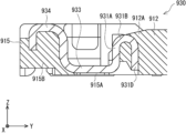
특허문헌 1(일본 공개특허공보 2015-185541호)은 커넥터 조립체에 있어서의 리셉터클 커넥터의 리셉터클 금구(金具)를 개시한다. 이와 같은 리셉터클 금구의 일례로서, 도9에 나타내는 리셉터클 홀드다운(930)이 있다.Patent Document 1 (Japanese Patent Application Laid-Open No. 2015-185541) discloses a receptacle fitting of a receptacle connector in a connector assembly. As an example of such a receptacle fitting, there is a receptacle hold down (930) shown in Fig. 9.
리셉터클 홀드다운(930)은 리셉터클 커넥터의 끝벽(915)과, 섬 형상부(912)를 덮는다. 리셉터클 홀드다운(930)은 아머부(931)와, 저부(933)와, 단부(934)를 구비한다. 리셉터클 홀드다운(930)은 곡면 형상을 따른 한 장의 판상체이고, 금속 재료로 이루어진다. 아머부(931)와 저부(933)와 단부(934)가 이 순서로 이어진다.The receptacle hold down (930) covers the end wall (915) of the receptacle connector and the island-shaped portion (912). The receptacle hold down (930) has an armor portion (931), a bottom portion (933), and an end portion (934). The receptacle hold down (930) is a single plate-shaped body along a curved shape and is made of a metal material. The armor portion (931), the bottom portion (933), and the end portion (934) are connected in this order.
아머부(931)는 리셉터클 커넥터의 섬 형상부(912)의 일부를 덮는다. 아머부(931)는 돌출부(931A)와 호상(弧狀)부(931B)를 구비한다. 커넥터 조립체에 있어서의 리셉터클 커넥터와 플러그 커넥터가 끼워맞춤하는 방향을 끼워맞춤 방향(여기서는, Z축 방향)으로 한다. 돌출부(931A)는 섬 형상부(912)의 측벽(912A)을 따라가면서 끼워맞춤 방향으로 돌출한다. 호상부(931B)는 돌출부(931A)로부터 끼워맞춤 방향으로 내뻗어 있다. 저부(933)는 끝벽(915)의 저부(915A)를 덮는다. 단부(934)는 끝벽(915)의 단부(915B)를 덮는다.The armor portion (931) covers a part of the island-shaped portion (912) of the receptacle connector. The armor portion (931) has a protrusion portion (931A) and an arcuate portion (931B). The direction in which the receptacle connector and the plug connector fit together in the connector assembly is referred to as the fitting direction (here, the Z-axis direction). The protrusion portion (931A) protrudes in the fitting direction along the side wall (912A) of the island-shaped portion (912). The arcuate portion (931B) extends from the protrusion portion (931A) in the fitting direction. The bottom portion (933) covers the bottom portion (915A) of the end wall (915). The end portion (934) covers the end portion (915B) of the end wall (915).
이와 같은 커넥터 조립체에 있어서, 소형화가 요구되고 있다. 리셉터클 홀드다운은, 커넥터 조립체의 사이즈에 영향을 미친다. 이와 같은 커넥터 조립체에 있어서, 커넥터 조립체의 소형화의 관점에서, 리셉터클 홀드다운의 형상에 대해 검토한다.In such connector assemblies, miniaturization is required. The receptacle hold-down affects the size of the connector assembly. In such connector assemblies, the shape of the receptacle hold-down is examined from the viewpoint of miniaturization of the connector assembly.
본 발명의 목적은 커넥터 조립체의 소형화를 도모하는 기술을 제공하는 것에 있다.The purpose of the present invention is to provide a technology for miniaturizing a connector assembly.
본 개시의 제1 관점에 의하면, 복수의 플러그 콘택트, 및 상기 복수의 플러그 콘택트를 홀딩하는 플러그 하우징을 구비한 플러그 커넥터와; 복수의 리셉터클 콘택트, 상기 복수의 리셉터클 콘택트를 홀딩하는 리셉터클 하우징, 및 상기 리셉터클 하우징에 있어서의 상기 복수의 리셉터클 콘택트의 외측에 장착된 리셉터클 홀드다운을 구비한 리셉터클 커넥터;를 구비하고, 상기 플러그 커넥터와 상기 리셉터클 커넥터를 끼워맞춤 방향에 있어서 서로 끼워맞춤함으로써 각 플러그 콘택트가 각 리셉터클 콘택트와 전기적으로 접촉하는 커넥터 조립체로서, 상기 복수의 리셉터클 콘택트는 피치 방향으로 배열되고, 상기 리셉터클 하우징은 상기 피치 방향으로 병렬하여 연장된 2개의 측벽과, 상기 2개의 측벽의 단부끼리를 연결하는 끝벽과, 상기 2개의 측벽과 상기 끝벽으로 둘러싸인 섬 형상부를 구비하고, 상기 리셉터클 홀드다운은 상기 섬 형상부의 일부를 덮는 아머부를 구비하고, 상기 아머부는 코이닝 성형부를 구비하는, 커넥터 조립체가 제공된다.According to a first aspect of the present disclosure, there is provided a plug connector having a plurality of plug contacts and a plug housing holding the plurality of plug contacts; A connector assembly is provided, comprising: a receptacle connector having a plurality of receptacle contacts, a receptacle housing holding the plurality of receptacle contacts, and a receptacle hold down mounted on the outside of the plurality of receptacle contacts in the receptacle housing; wherein the plug connector and the receptacle connector are fitted together in a fitting direction so that each plug contact electrically contacts each receptacle contact, wherein the plurality of receptacle contacts are arranged in a pitch direction, the receptacle housing has two side walls extending in parallel in the pitch direction, an end wall connecting end portions of the two side walls, and an island-shaped portion surrounded by the two side walls and the end wall, and the receptacle hold down has an armor portion covering a portion of the island-shaped portion, and the armor portion has a coining forming portion.
본 개시에 의하면, 커넥터 조립체의 소형화를 도모할 수 있다.According to the present disclosure, miniaturization of a connector assembly can be achieved.
본 개시의 상기 및 다른 목적, 특징 및 효과는 아래의 발명의 상세한 설명 및 단지 예시의 방식으로 제공된 첨부 도면으로부터 더 명확하게 이해될 것이며, 따라서 본 개시를 제한하는 것으로 간주되지 않아야 한다.The above and other objects, features and effects of the present disclosure will be more clearly understood from the detailed description of the invention below and the accompanying drawings, which are provided by way of illustration only, and therefore should not be considered as limiting the present disclosure.
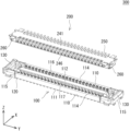
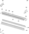
도 1은 전기적인 접속이 해제된 리셉터클 커넥터 및 플러그 커넥터의 사시도이다.
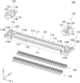
도 2는 리셉터클 커넥터의 분해 사시도이다.
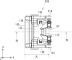
도 3은 리셉터클 커넥터의 단부 근방의 평면도이다.
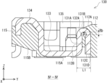
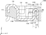
도 4는 도 3의 IV-IV 화살표에서 보는 단면도이다.
도 5는 플러그 커넥터의 분해 사시도이다.
도 6은 리셉터클 커넥터의 단면도이다. (제1 변형예)
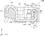
도 7은 리셉터클 커넥터의 단면도이다. (제2 변형예)
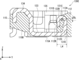
도 8은 리셉터클 커넥터의 단면도이다. (제3 변형예)
도 9는 특허문헌1의 리셉터클 금구의 일례를 나타내는 도면이다.Figure 1 is a perspective view of a receptacle connector and a plug connector with the electrical connection disconnected.
Figure 2 is an exploded perspective view of the receptacle connector.
Figure 3 is a plan view of the vicinity of one end of the receptacle connector.
Figure 4 is a cross-sectional view taken along arrow IV-IV of Figure 3.
Figure 5 is an exploded perspective view of the plug connector.
Fig. 6 is a cross-sectional view of a receptacle connector. (First modified example)
Fig. 7 is a cross-sectional view of a receptacle connector. (Second modified example)
Fig. 8 is a cross-sectional view of a receptacle connector. (Third modification)
Figure 9 is a drawing showing an example of the receptacle fitting of Patent Document 1.
이하, 본 발명을 적용한 구체적인 실시형태에 대해, 도면을 참조하면서 상세하게 설명한다. 단, 본 발명이 이하의 실시형태에 한정되는 것은 아니다. 또한, 설명을 명확하게 하기 위해, 이하의 기재 및 도면은 적절히 간략화되어 있다.Hereinafter, specific embodiments to which the present invention is applied will be described in detail with reference to the drawings. However, the present invention is not limited to the embodiments below. In addition, for the purpose of clarity of explanation, the description and drawings below are appropriately simplified.
또한, 당연히, 도 1 및 그 밖의 도면에 나타낸 오른편 XYZ좌표는 구성 요소의 위치 관계를 설명하기 위한 편의적인 것이며, 후술하는 리셉터클 커넥터(100), 플러그 커넥터(200) 등의 실제의 사용 상태에 있어서의 자세를 시사하는 것은 아니다. 통상, X축 방향이 폭 방향이고, Y축 방향이 피치 방향이며, Z축 방향이 후술하는 리셉터클 커넥터(100) 및 플러그 커넥터(200)가 끼워맞춤하는 끼워맞춤 방향이고, XY평면이 수평면이며, 도면간에 공통이다.In addition, of course, the right-hand XYZ coordinates shown in FIG. 1 and other drawings are for convenience of explaining the positional relationship of the components, and do not indicate the posture in the actual usage state of the receptacle connector (100), plug connector (200), etc. described later. Normally, the X-axis direction is the width direction, the Y-axis direction is the pitch direction, the Z-axis direction is the fitting direction in which the receptacle connector (100) and plug connector (200) described later fit together, and the XY plane is a horizontal plane and is common among the drawings.
<실시형태><Implementation form>
이하, 도 1에서 도 5를 참조하여 본 개시의 실시형태를 설명한다.Hereinafter, embodiments of the present disclosure will be described with reference to FIGS. 1 to 5.
도 1에 나타내는 바와 같이, 커넥터 조립체(300)는 리셉터클 커넥터(100)와 플러그 커넥터(200)를 구비한다. 도 1 및 도 2에 나타내는 리셉터클 커넥터(100)는 수용 공간(116)이 상측(여기서는, Z축 정(正)방향)을 향하도록 배치되어 있다. 도1에 나타내는 플러그 커넥터(200)는 수용 공간(246)이 하측(여기서는, Z축 부(負)방향)을 향하도록 배치되어 있다. 도 5는 도 1에 나타내는 플러그 커넥터의 분해 사시도이다. 도 5에 나타내는 플러그 커넥터(200)는 도 1에 나타내는 플러그 커넥터(200)와 달리, 수용 공간(246)이 상측을 향하도록 배치되어 있다.As shown in Fig. 1, the connector assembly (300) has a receptacle connector (100) and a plug connector (200). The receptacle connector (100) shown in Figs. 1 and 2 is arranged so that the receiving space (116) faces upward (here, the positive Z-axis direction). The plug connector (200) shown in Fig. 1 is arranged so that the receiving space (246) faces downward (here, the negative Z-axis direction). Fig. 5 is an exploded perspective view of the plug connector shown in Fig. 1. Unlike the plug connector (200) shown in Fig. 1, the plug connector (200) shown in Fig. 5 is arranged so that the receiving space (246) faces upward.
리셉터클 커넥터(100)는 복수의 리셉터클 콘택트(120)와, 리셉터클 하우징(110)과, 리셉터클 홀드다운(130)을 구비한다.A receptacle connector (100) has a plurality of receptacle contacts (120), a receptacle housing (110), and a receptacle hold down (130).
리셉터클 하우징(110)은 복수의 리셉터클 콘택트(120)를 홀딩한다. 리셉터클 홀드다운(130)은 리셉터클 하우징(110)에 있어서의 복수의 리셉터클 콘택트(120)의 외측에 장착된다.A receptacle housing (110) holds a plurality of receptacle contacts (120). A receptacle hold down (130) is mounted on the outside of the plurality of receptacle contacts (120) in the receptacle housing (110).
도 1 및 도 5에 나타내는 바와 같이, 플러그 커넥터(200)는 복수의 플러그 콘택트(250)와, 플러그 하우징(240)과, 플러그 홀드다운(260)을 구비한다. 플러그 하우징(240)은 복수의 플러그 콘택트(250)를 홀딩한다.As shown in FIG. 1 and FIG. 5, the plug connector (200) has a plurality of plug contacts (250), a plug housing (240), and a plug hold-down (260). The plug housing (240) holds a plurality of plug contacts (250).
본 실시형태에 따른 리셉터클 커넥터(100)와 플러그 커넥터(200)는 각각, 상이한 회로 기판에 실장할 수 있다. 리셉터클 커넥터(100)와 플러그 커넥터(200)는 표면 실장품으로서 이용해도 되고, 예를 들어 납땜을 사용하여 프린트 기판에 실장되어도 된다. 리셉터클 커넥터(100)와 플러그 커넥터(200)는 회로 기판용 커넥터로서 이용할 수 있다. 플러그 커넥터(200)와 리셉터클 커넥터(100)를 끼워맞춤 방향(여기서는, Z축 방향)에 있어서 서로 끼워맞춤함으로써, 각 플러그 콘택트(250)가 각 리셉터클 콘택트(120)와 전기적으로 접촉한다. 이로써, 상이한 회로 기판끼리를 전기적으로 접속할 수 있다.The receptacle connector (100) and the plug connector (200) according to the present embodiment can be mounted on different circuit boards, respectively. The receptacle connector (100) and the plug connector (200) can be used as surface-mounted products, and can be mounted on a printed circuit board using, for example, soldering. The receptacle connector (100) and the plug connector (200) can be used as connectors for a circuit board. By fitting the plug connector (200) and the receptacle connector (100) to each other in the fitting direction (here, the Z-axis direction), each plug contact (250) electrically contacts each receptacle contact (120). As a result, different circuit boards can be electrically connected to each other.
다음으로, 커넥터 조립체(300)의 구성의 상세에 대하여 설명한다.Next, the details of the configuration of the connector assembly (300) will be described.
도 1 및 도 2에 나타내는 바와 같이, 리셉터클 하우징(110)은 예를 들어, 대략 직육면체이다. 리셉터클 하우징(110)은 예를 들어, 전기 절연 재료를 사용하여 성형된다. 전기 절연 재료는 예를 들어, 수지 재료 등이다. 도 2에 나타내는 바와 같이, 리셉터클 하우징(110)은 저부(111)와, 섬 형상부(112)와, 2개의 측벽(114)과, 끝벽(115)을 구비한다.As shown in FIG. 1 and FIG. 2, the receptacle housing (110) is, for example, an approximately rectangular parallelepiped. The receptacle housing (110) is formed using, for example, an electrically insulating material. The electrically insulating material is, for example, a resin material. As shown in FIG. 2, the receptacle housing (110) has a bottom portion (111), an island-shaped portion (112), two side walls (114), and an end wall (115).
저부(111)는 피치 방향(여기서는, Y축 방향)으로 연장된 판상부여도 된다. 섬 형상부(112)는 저부(111)에서 상방(여기서는, Z축 정방향)으로 솟아오르는 것과 동시에, 피치 방향(여기서는, Y축 방향)으로 연장된다. 2개의 측벽(114)은 저부(111)에서 상방으로 솟아오르는 것과 동시에 피치 방향으로 연장된다. 2개의 측벽(114)은 병렬 배치되고, 섬 형상부(112)는 2개의 측벽(114) 사이에 배치된다. 끝벽(115)은 2개의 측벽(114)의 단부끼리를 연결한다. 끝벽(115)과 섬 형상부(112)는 이격되어 있어도 된다. 리셉터클 하우징(110)은 끝벽(115)을 2개 구비하여도 된다. 2개의 끝벽(115)은 각각, 상이한 2개의 측벽(114)의 단부끼리를 연결한다. 2개의 측벽(114)과 2개의 끝벽(115)은 섬 형상부(112)를 둘러싸면 된다. 2개의 측벽(114)과 2개의 끝벽(115)과, 섬 형상부(112)의 사이에는 수용 공간(116)이 형성된다. 수용 공간(116)은 섬 형상부(112)를 둘러싸는 프레임 형상체이다. 플러그 커넥터(200)와 리셉터클 커넥터(100)를 끼워맞춤한 경우, 수용 공간(116)은 플러그 커넥터(200)의 일부, 예를 들어, 측벽(244) 및 끝벽(245)을 수용 가능한 크기를 갖는다.The bottom (111) may be a plate-shaped portion extending in the pitch direction (here, the Y-axis direction). The island-shaped portion (112) rises upward from the bottom (111) (here, in the positive Z-axis direction) and extends in the pitch direction (here, the Y-axis direction). The two side walls (114) rise upward from the bottom (111) and extend in the pitch direction. The two side walls (114) are arranged in parallel, and the island-shaped portion (112) is arranged between the two side walls (114). The end wall (115) connects the ends of the two side walls (114). The end wall (115) and the island-shaped portion (112) may be spaced apart from each other. The receptacle housing (110) may have two end walls (115). The two end walls (115) each connect the ends of two different side walls (114). The two side walls (114) and the two end walls (115) surround the island-shaped portion (112). An accommodation space (116) is formed between the two side walls (114) and the two end walls (115) and the island-shaped portion (112). The accommodation space (116) is a frame-shaped body surrounding the island-shaped portion (112). When the plug connector (200) and the receptacle connector (100) are fitted together, the accommodation space (116) has a size capable of accommodating a part of the plug connector (200), for example, the side wall (244) and the end wall (245).
끝벽(115)은 저부(115A)와, 단부(115B)와, 측부(115C, 115D)를 구비한다. 저부(115A)는 저부(111)에서 피치 방향으로 연장된 판상부이다. 측부(115C, 115D)는 저부(111)에서 상방으로 솟아오르는 것과 동시에 피치 방향으로 연장된다. 측부(115C, 115D)는 병렬 배치되어, 대향한다. 단부(115B)는 측부(115C)의 단부와 측부(115D)의 단부를 연결한다.The end wall (115) has a bottom portion (115A), an end portion (115B), and side portions (115C, 115D). The bottom portion (115A) is a plate-shaped portion that extends in the pitch direction from the bottom portion (111). The side portions (115C, 115D) rise upward from the bottom portion (111) and extend in the pitch direction at the same time. The side portions (115C, 115D) are arranged in parallel and face each other. The end portion (115B) connects the end of the side portion (115C) and the end of the side portion (115D).
복수의 리셉터클 콘택트(120)는 리셉터클 하우징(110) 내에 있어서, 피치 방향(여기서는, Y축 방향)으로 배열된다. 피치 방향은 리셉터클 하우징(110)의 길이 방향과 동일하다. 도 2에 나타내는 복수의 리셉터클 콘택트(120)는 피치 방향으로 2열로 배열되어 있다. 측벽(114)은 복수의 콘택트 홀딩 홈(117)을 구비하여도 된다. 각 리셉터클 콘택트(120)가 각 콘택트 홀딩 홈(117)에 배치됨으로써, 리셉터클 하우징(110)이 복수의 리셉터클 콘택트(120)를 홀딩해도 된다. 콘택트 홀딩 홈(117)은 피치 방향으로 등간격으로 늘어서도 된다. 2개의 측벽(114)이 각각, 복수의 콘택트 홀딩 홈(117)을 구비하여도 된다. 각 리셉터클 콘택트(120)는 섬 형상부(112)의 길이 방향으로 연장되는 직선을 중심선으로 하여 선대칭으로 배치되어도 된다. 각 콘택트 홀딩 홈(117)은 섬 형상부(112)의 측면, 저부(111)의 상면, 측벽(114)의 내측면에 있어서 연속해서 연장되어도 된다. 측벽(114)의 내측면은 섬 형상부(112)의 측면과 대향한다.A plurality of receptacle contacts (120) are arranged in a pitch direction (here, the Y-axis direction) within a receptacle housing (110). The pitch direction is the same as the longitudinal direction of the receptacle housing (110). The plurality of receptacle contacts (120) shown in Fig. 2 are arranged in two rows in the pitch direction. The side wall (114) may have a plurality of contact holding grooves (117). By arranging each receptacle contact (120) in each contact holding groove (117), the receptacle housing (110) may hold the plurality of receptacle contacts (120). The contact holding grooves (117) may be arranged at equal intervals in the pitch direction. Each of the two side walls (114) may have a plurality of contact holding grooves (117). Each receptacle contact (120) may be arranged symmetrically about a straight line extending in the length direction of the island-shaped portion (112) as a center line. Each contact holding groove (117) may extend continuously on the side surface of the island-shaped portion (112), the upper surface of the bottom portion (111), and the inner surface of the side wall (114). The inner surface of the side wall (114) faces the side surface of the island-shaped portion (112).
리셉터클 홀드다운(130)은 리셉터클 하우징(110)에 있어서의 복수의 리셉터클 콘택트(120)의 외측에 장착된다. 구체적으로는, 리셉터클 홀드다운(130)은 2개의 측벽(114)의 일부와, 끝벽(115)과, 섬 형상부(112)에 압입됨으로써 장착된다. 리셉터클 홀드다운(130)은 리셉터클 하우징(110)을 보강한다. 리셉터클 홀드다운(130)은 도시되지 않은 회로 기판 측의 전원 등과 전기적으로 접속 가능한 단자로서 이용할 수 있다. 리셉터클 홀드다운(130)과 플러그 홀드다운(260)이 끼워맞춤 가능하면, 플러그 커넥터(200)와 리셉터클 커넥터(100)를 부드럽게 끼워맞춤할 수 있다. 즉, 리셉터클 홀드다운(130)은 플러그 커넥터(200)와 리셉터클 커넥터(100)의 전기적인 접속이나 끼워맞춤을 위해 이용할 수 있다.The receptacle hold down (130) is mounted on the outside of a plurality of receptacle contacts (120) in the receptacle housing (110). Specifically, the receptacle hold down (130) is mounted by being press-fitted into parts of two side walls (114), an end wall (115), and an island-shaped portion (112). The receptacle hold down (130) reinforces the receptacle housing (110). The receptacle hold down (130) can be used as a terminal that can be electrically connected to a power supply or the like on a circuit board side that is not shown. If the receptacle hold down (130) and the plug hold down (260) can be fitted together, the plug connector (200) and the receptacle connector (100) can be smoothly fitted together. That is, the receptacle hold down (130) can be used for electrical connection or fitting of the plug connector (200) and the receptacle connector (100).
도 2 내지 도 4에 나타내는 바와 같이, 리셉터클 홀드다운(130)은 끝벽(115)과, 섬 형상부(112)의 일부를 덮는다. 리셉터클 홀드다운(130)은 아머부(131)와, 저부(133)와, 단부(134)와, 측부(135, 136)를 구비한다.As shown in FIGS. 2 to 4, the receptacle hold down (130) covers the end wall (115) and a portion of the island-shaped portion (112). The receptacle hold down (130) has an armor portion (131), a bottom portion (133), an end portion (134), and side portions (135, 136).
아머부(131)는 곡면 형상을 따른 한 장의 판상체이고, 금속 재료로 이루어진다. 단부(134)와, 저부(133)와, 아머부(131)가 피치 방향(여기서는, Y축 방향)에 있어서, 이 순서로 이어진다. 측부(136)와, 저부(133)와, 측부(135)가 폭 방향(여기서는, X축 방향)에 있어서, 이 순서로 이어진다. 저부(133)는 끝벽(115)의 저부(115A)를 덮고, 단부(134)는 끝벽(115)의 단부(115B)를 덮는다. 측부(135)는 끝벽(115)의 측부(115C)를 덮고, 측부(136)는 끝벽(115)의 측부(115D)를 덮는다.The armor part (131) is a single plate-shaped body following a curved shape and is made of a metal material. The end part (134), the bottom part (133), and the armor part (131) are connected in this order in the pitch direction (here, the Y-axis direction). The side part (136), the bottom part (133), and the side part (135) are connected in this order in the width direction (here, the X-axis direction). The bottom part (133) covers the bottom part (115A) of the end wall (115), and the end part (134) covers the end part (115B) of the end wall (115). The side part (135) covers the side part (115C) of the end wall (115), and the side part (136) covers the side part (115D) of the end wall (115).
아머부(131)는 리셉터클 커넥터(100)의 섬 형상부(112)의 일부를 덮는다. 아머부(131)는 돌출부(131A)와, 호상부(131B)와, 선단부(131D)를 구비한다. 돌출부(131A)는 섬 형상부(112)의 단부(112A)를 따라가면서 끼워맞춤 방향(여기서는, Z축 방향)에 있어서의 플러그 커넥터(200)측(여기서는, Z축 정방향)으로 돌출한다. 도 4에 나타내는 돌출부(131A)의 일례는 단부(112A)의 벽면(112B)을 따른다. 호상부(131B)는 돌출부(131A)로부터 끼워맞춤 방향에 있어서의 플러그 커넥터(200)측으로 내뻗어 있다. 호상부(131B)는, 곡률 반경(Rb)으로 구부러진다. 선단부(131D)는, 호상부(131B)로부터 끼워맞춤 방향에 있어서의 리셉터클 커넥터(100)측(여기서는, Z축 부방향)으로 연장된다. 도4에 나타내는 선단부(131D)의 일례는 단부(112A)의 구멍(112C)에 삽입된다.The armor portion (131) covers a part of the island-shaped portion (112) of the receptacle connector (100). The armor portion (131) has a protrusion portion (131A), an arc-shaped portion (131B), and a tip portion (131D). The protrusion portion (131A) protrudes toward the plug connector (200) (here, in the positive Z-axis direction) in the fitting direction (here, in the Z-axis direction) along the end portion (112A) of the island-shaped portion (112). An example of the protrusion portion (131A) shown in Fig. 4 follows the wall surface (112B) of the end portion (112A). The arc-shaped portion (131B) extends from the protrusion portion (131A) toward the plug connector (200) in the fitting direction. The arc-shaped portion (131B) is bent with a radius of curvature (Rb). The tip portion (131D) extends from the upper portion (131B) toward the receptacle connector (100) in the fitting direction (here, in the negative Z-axis direction). An example of the tip portion (131D) shown in Fig. 4 is inserted into the hole (112C) of the end portion (112A).
아머부(131)는 코이닝 성형부(132A)를 구비한다. 코이닝 성형부(132A)는 호상부(131B)에 형성된다. 구체적으로는, 코이닝 성형부(132A)는 호상부(131B)의 내측 표면, 바꾸어 말하면, 끼워맞춤 방향에 있어서의 리셉터클 커넥터(100)측 표면에 형성되어 있다. 코이닝 성형부(132A)는 코이닝 가공에 의해 성형되어 있다. 코이닝 성형부(132A)의 두께는 리셉터클 홀드다운(130)의 다른 부위의 두께에 비해 작다. 리셉터클 홀드다운(130)의 다른 부위는 예를 들어, 돌출부(131A), 단부(134)이며, 코이닝 가공이 실시되지 않아도 된다.The armor part (131) has a coining forming part (132A). The coining forming part (132A) is formed on the arc-shaped part (131B). Specifically, the coining forming part (132A) is formed on the inner surface of the arc-shaped part (131B), in other words, on the surface on the receptacle connector (100) side in the fitting direction. The coining forming part (132A) is formed by coining processing. The thickness of the coining forming part (132A) is smaller than the thickness of other parts of the receptacle hold-down (130). Other parts of the receptacle hold-down (130) are, for example, the protrusion (131A) and the end (134), and coining processing does not have to be performed.
리셉터클 홀드다운(130)의 제조 방법의 일례에 대해 설명한다. 먼저, 금속 재료로 이루어진 판재를 타발하여, 타발 가공체를 형성한다. 계속해서, 코이닝 가공을 타발 가공체에 있어서의 아머부(131)에 상당하는 부위에 실시하여, 코이닝 성형부(132A)에 상당하는 부위를 형성한다. 마지막으로, 타발 가공체를 프레스 가공에 의해 구부려 아머부(131)와, 저부(133)와, 단부(134)와, 측부(135, 136)를 형성한다. 상기한 바와 같이, 코이닝 성형부(132A)의 두께는 리셉터클 홀드다운(130)의 다른 부위의 두께에 비해 작기 때문에, 이 형성된 아머부(131)의 호상부(131B)의 곡률 반경(Rb)은 작다. 이상으로부터, 리셉터클 홀드다운(130)을 제조할 수 있다.Hereinafter, an example of a method for manufacturing a receptacle hold-down (130) will be described. First, a plate made of a metal material is punched to form a punched body. Subsequently, coining is performed on a portion corresponding to an armor portion (131) in the punched body, thereby forming a portion corresponding to a coining-formed portion (132A). Finally, the punched body is bent by press working to form an armor portion (131), a bottom portion (133), an end portion (134), and side portions (135, 136). As described above, since the thickness of the coining-formed portion (132A) is smaller than the thickness of other portions of the receptacle hold-down (130), the radius of curvature (Rb) of the arc-shaped portion (131B) of the formed armor portion (131) is small. From the above, the receptacle hold-down (130) can be manufactured.
도 1 및 도 5에 나타내는 바와 같이, 플러그 하우징(240)은 예를 들어, 대략 직육면체이다. 플러그 하우징(240)은 예를 들어, 전기 절연 재료를 사용하여 성형된다. 전기 절연 재료는 예를 들어, 수지 재료 등이다. 도 5에 나타내는 바와 같이, 플러그 하우징(240)은 저부(241)와, 2개의 측벽(244)과, 끝벽(245)을 구비한다.As shown in FIG. 1 and FIG. 5, the plug housing (240) is, for example, an approximately rectangular parallelepiped. The plug housing (240) is formed using, for example, an electrically insulating material. The electrically insulating material is, for example, a resin material. As shown in FIG. 5, the plug housing (240) has a bottom (241), two side walls (244), and an end wall (245).
저부(241)는 피치 방향(여기서는, Y축 방향)으로 연장된 판상부여도 된다. 2개의 측벽(244)은 저부(241)에서 상방으로 솟아오르는 것과 동시에 피치 방향으로 연장된다. 2개의 측벽(244)은 병렬하여 배치된다. 끝벽(245)은 2개의 측벽(244)의 단부끼리를 연결한다.The bottom (241) may be a plate-shaped portion extending in the pitch direction (here, in the Y-axis direction). The two side walls (244) rise upward from the bottom (241) and extend in the pitch direction at the same time. The two side walls (244) are arranged in parallel. The end wall (245) connects the ends of the two side walls (244).
플러그 하우징(240)은 끝벽(245)을 2개 구비하여도 된다. 2개의 끝벽(245)은 각각, 상이한 2개의 측벽(244)의 단부끼리를 연결한다. 2개의 측벽(244)과 2개의 끝벽(245)은 프레임 형상체여도 된다. 2개의 측벽(244)과 2개의 끝벽(245)의 사이에는, 수용 공간(246)이 형성된다. 수용 공간(246)은 대략 직육면체이다. 플러그 커넥터(200)와 리셉터클 커넥터(100)(도1 참조)를 끼워맞춤한 경우, 수용 공간(246)은 리셉터클 커넥터(100)의 일부, 예를 들어, 도 1에 나타내는 섬 형상부(112)를 수용 가능한 크기를 갖는다.The plug housing (240) may have two end walls (245). The two end walls (245) each connect the ends of two different side walls (244). The two side walls (244) and the two end walls (245) may be frame-shaped. An accommodation space (246) is formed between the two side walls (244) and the two end walls (245). The accommodation space (246) is approximately a rectangular parallelepiped. When the plug connector (200) and the receptacle connector (100) (see FIG. 1) are fitted together, the accommodation space (246) has a size capable of accommodating a part of the receptacle connector (100), for example, an island-shaped portion (112) shown in FIG. 1.
복수의 플러그 콘택트(250)는 플러그 하우징(240) 내에 있어서, 피치 방향(여기서는, Y축 방향)으로 배열된다. 피치 방향은 플러그 하우징(240)의 길이 방향과 동일하다. 도 2에 나타내는 복수의 플러그 콘택트(250)는 피치 방향으로 2열로 배열되어 있다. 금속 재료로 이루어진 판재를 타발하여, 띠 형상편을 형성한다. 또한, 띠 형상편을 구부리는 등 하여 플러그 콘택트(250)를 제조하면 된다. 각 플러그 콘택트(250)가 2개의 측벽(244)의 사이에 일체 몰드 성형 또는 압입됨으로써, 플러그 하우징(240)이 복수의 플러그 콘택트(250)를 홀딩해도 된다. 복수의 플러그 콘택트(250)는 플러그 하우징(240) 내에 있어서, 피치 방향으로 등간격으로 늘어서도 된다.A plurality of plug contacts (250) are arranged in the pitch direction (here, the Y-axis direction) within the plug housing (240). The pitch direction is the same as the longitudinal direction of the plug housing (240). The plurality of plug contacts (250) shown in Fig. 2 are arranged in two rows in the pitch direction. A plate made of a metal material is punched to form a band-shaped piece. In addition, the plug contacts (250) may be manufactured by bending the band-shaped piece, etc. Each plug contact (250) may be integrally molded or press-fitted between two side walls (244), so that the plug housing (240) may hold the plurality of plug contacts (250). The plurality of plug contacts (250) may be lined up at equal intervals in the pitch direction within the plug housing (240).
플러그 커넥터(200)는 추가로 플러그 홀드다운(260)을 구비하여도 된다. 플러그 홀드다운(260)은 플러그 하우징(240)에 있어서의 복수의 플러그 콘택트(250)의 외측에 장착된다. 구체적으로는, 플러그 홀드다운(260)은 2개의 측벽(244)의 일부와 끝벽(245)에 일체 몰드 성형 또는 압입에 의해 장착된다. 이로써, 플러그 홀드다운(260)은 플러그 하우징(240)을 보강한다. 금속 재료로 이루어진 한 장의 판상체를 타발하여, 타발 가공체를 형성한다. 또한, 타발 가공체를 구부리는 등 하여, 플러그 홀드다운(260)을 제조하면 된다. 플러그 홀드다운(260)은 도시되지 않은 회로 기판 측의 전원 등과 전기적으로 접속 가능한 단자로서 이용할 수 있다.The plug connector (200) may additionally have a plug hold-down (260). The plug hold-down (260) is mounted on the outside of a plurality of plug contacts (250) in the plug housing (240). Specifically, the plug hold-down (260) is mounted on a part of two side walls (244) and an end wall (245) by integral mold forming or press-fitting. As a result, the plug hold-down (260) reinforces the plug housing (240). A single plate-shaped body made of a metal material is punched to form a punched body. In addition, the plug hold-down (260) may be manufactured by bending the punched body, etc. The plug hold-down (260) can be used as a terminal that can be electrically connected to a power supply, etc. on the circuit board side (not shown).
이상, 커넥터 조립체(300)의 구성에 의하면, 코이닝 성형부(132A)의 두께는 리셉터클 홀드다운(130)의 다른 부위의 두께에 비해 작다. 이로써, 상기한 리셉터클 홀드다운(130)의 제조 방법의 일례의 프레스 가공에 있어서, 작은 곡률 반경(Rb)으로 구부러지는 호상부(131B)를 구비한 아머부(131)을 형성할 수 있다. 호상부(131B)의 곡률 반경(Rb)이 작기 때문에, 아머부(131)의 피치 방향에 있어서의 길 L1, 바꾸어 말하면, 돌출부(131A)에서 선단부(131D)까지의 길이 L1의 단축을 도모할 수 있다. 이로써, 도 3에 도시하는 길이 LA를 단축할 수 있다. 따라서, 커넥터 조립체(300)의 소형화를 도모할 수 있다.Above, according to the configuration of the connector assembly (300), the thickness of the coining forming portion (132A) is smaller than the thickness of other portions of the receptacle hold-down (130). Accordingly, in the press working of an example of the manufacturing method of the receptacle hold-down (130) described above, it is possible to form an armor portion (131) having an arc-shaped portion (131B) that is bent with a small radius of curvature (Rb). Since the radius of curvature (Rb) of the arc-shaped portion (131B) is small, it is possible to shorten the length L1 of the armor portion (131) in the pitch direction, in other words, the length L1 from the protrusion (131A) to the tip (131D). Accordingly, the length LA shown in Fig. 3 can be shortened. Therefore, it is possible to miniaturize the connector assembly (300).
(제1 변형예)(Variation 1)
다음으로, 도 6을 참조하여, 리셉터클 홀드다운(130)의 제1 변형예에 대해 설명한다. 도 6에 나타내는 리셉터클 홀드다운(130A)는, 리셉터클 홀드다운(130)의 제1 변형예이며, 코이닝 성형부를 제외하고 리셉터클 홀드다운(130)과 동일한 구성을 구비한다.Next, with reference to Fig. 6, a first modified example of the receptacle hold down (130) will be described. The receptacle hold down (130A) shown in Fig. 6 is a first modified example of the receptacle hold down (130) and has the same configuration as the receptacle hold down (130) except for the coining forming portion.
리셉터클 홀드다운(130A)은 코이닝 성형부(132B)를 구비한다. 코이닝 성형부(132B)는, 호상부(131B)에 형성된다. 구체적으로는, 코이닝 성형부(132B)는 호상부(131B)의 내측 표면, 바꾸어 말하면, 끼워맞춤 방향에 있어서의 리셉터클 커넥터(100) 측 표면에 형성되어 있다. 코이닝 성형부(132B)는, 호상부(131B)에서 선단부(131D)까지 연장된다. 코이닝 성형부(132B)의 두께는 코이닝 성형부(132A)의 두께와 마찬가지로, 리셉터클 홀드다운(130)의 다른 부위의 두께에 비해 작다. 리셉터클 홀드다운(130A)의 제조 방법의 프레스 가공에 있어서, 상기한 리셉터클 홀드다운(130)의 제조 방법의 일례의 프레스 가공과 마찬가지로, 작은 곡률 반경(Rb)으로 구부러지는 호상부(131B)를 구비한 아머부(131)를 형성할 수 있다. 호상부(131B)의 곡률 반경(Rb)이 작기 때문에, 아머부(131)의 피치 방향에 있어서의 길이 L2, 바꾸어 말하면, 돌출부(131A)에서 선단부(131D)까지의 길이 L2의 단축을 도모할 수 있다. 따라서, 커넥터 조립체(300)의 소형화를 도모할 수 있다.The receptacle hold down (130A) has a coining forming portion (132B). The coining forming portion (132B) is formed on the arc-shaped portion (131B). Specifically, the coining forming portion (132B) is formed on the inner surface of the arc-shaped portion (131B), in other words, on the surface on the receptacle connector (100) side in the fitting direction. The coining forming portion (132B) extends from the arc-shaped portion (131B) to the tip portion (131D). The thickness of the coining forming portion (132B) is smaller than the thickness of other portions of the receptacle hold down (130), similar to the thickness of the coining forming portion (132A). In the press working of the manufacturing method of the receptacle hold-down (130A), similarly to the press working of the example of the manufacturing method of the receptacle hold-down (130) described above, it is possible to form an armor portion (131) having an arc-shaped portion (131B) that is bent with a small radius of curvature (Rb). Since the radius of curvature (Rb) of the arc-shaped portion (131B) is small, it is possible to shorten the length L2 of the armor portion (131) in the pitch direction, in other words, the length L2 from the protrusion (131A) to the tip (131D). Therefore, it is possible to miniaturize the connector assembly (300).
(제2 변형예)(2nd variation)
다음으로, 도 7을 참조하여, 리셉터클 홀드다운(130)의 제2 변형예에 대해 설명한다. 도 7에 나타내는 리셉터클 홀드다운(130B)은 리셉터클 홀드다운(130)의 제2 변형예이며, 호상부를 제외하고 리셉터클 홀드다운(130)과 동일한 구성을 구비한다.Next, with reference to Fig. 7, a second modified example of the receptacle hold down (130) will be described. The receptacle hold down (130B) shown in Fig. 7 is a second modified example of the receptacle hold down (130) and has the same configuration as the receptacle hold down (130) except for the upper portion.
리셉터클 홀드다운(130B)는 삽입부(131E)와, 호상부(131C)와, 선단부(131D)를 구비한다. 호상부(131C)는 곡률 반경(Rc)으로 구부러진다. 삽입부(131E)는 섬 형상부(112)의 단부(112A) 내의 구멍(112C)에 삽입되면서 끼워맞춤 방향으로 연장된다. 삽입부(131E)는 끼워맞춤 방향에 있어서의 플러그 커넥터(200)측(여기서는, Z축 정방향)으로 연장된다. 호상부(131C)는 삽입부(131E)에서 끼워맞춤 방향에 있어서의 플러그 커넥터(200)측으로 내뻗어 있다. 호상부(131C)는 삽입부(131E)보다 피치 방향에 있어서의 끝벽(115)측(여기서는, Y축 부방향)으로 연장된다. 선단부(131D)는 호상부(131C)에서 끼워맞춤 방향에 있어서의 리셉터클 커넥터(100)측(여기서는, Z축 부방향)으로 연장된다. 도 7에 나타내는 선단부(131D)의 일례는 단부(112A)의 벽면(112B)을 따른다. 코이닝 성형부(132A)의 두께는 리셉터클 홀드다운(130)의 다른 부위의 두께에 비해 작다. 리셉터클 홀드다운(130B)의 제조 방법의 프레스 가공에 있어서, 상기한 리셉터클 홀드다운(130)의 제조 방법의 일례의 프레스 가공과 마찬가지로, 작은 곡률 반경(Rc)으로 구부러지는 호상부(131C)를 구비한 아머부(131)를 형성할 수 있다. 호상부(131C)의 곡률 반경(Rc)이 작기 때문에, 아머부(131)의 피치 방향에 있어서의 길이 L3, 바꾸어 말하면, 삽입부(131E)에서 선단부(131D)까지의 길이 L3의 단축을 도모할 수 있다. 그 때문에, 리셉터클 홀드다운(130)과 마찬가지로, 커넥터 조립체(300)의 소형화를 도모할 수 있다.The receptacle hold-down (130B) has an insertion portion (131E), an arc portion (131C), and a tip portion (131D). The arc portion (131C) is bent with a radius of curvature (Rc). The insertion portion (131E) is inserted into a hole (112C) in an end portion (112A) of an island-shaped portion (112) and extends in a fitting direction. The insertion portion (131E) extends toward the plug connector (200) in the fitting direction (here, in the positive Z-axis direction). The arc portion (131C) extends from the insertion portion (131E) toward the plug connector (200) in the fitting direction. The arc portion (131C) extends toward the end wall (115) in the pitch direction (here, in the negative Y-axis direction) from the insertion portion (131E). The tip portion (131D) extends from the arc portion (131C) toward the receptacle connector (100) in the fitting direction (here, in the negative Z-axis direction). An example of the tip portion (131D) shown in Fig. 7 follows the wall surface (112B) of the end portion (112A). The thickness of the coining forming portion (132A) is smaller than the thickness of other portions of the receptacle hold-down (130). In the press working of the manufacturing method of the receptacle hold-down (130B), similarly to the press working of the example of the manufacturing method of the receptacle hold-down (130) described above, an armor portion (131) having an arc portion (131C) that is bent with a small radius of curvature (Rc) can be formed. Since the radius of curvature (Rc) of the upper portion (131C) is small, the length L3 in the pitch direction of the armor portion (131), in other words, the length L3 from the insertion portion (131E) to the tip portion (131D), can be shortened. Therefore, similar to the receptacle hold-down (130), the miniaturization of the connector assembly (300) can be achieved.
(제3 변형예)(3rd variation)
다음으로, 도 8을 참조하여, 리셉터클 홀드다운(130)의 제3 변형예에 대해 설명한다. 도 8에 나타내는 리셉터클 홀드다운(130C)은 리셉터클 홀드다운(130)의 제3 변형예이며, 코이닝 성형부 및 호상부를 제외하고 리셉터클 홀드다운(130)과 동일한 구성을 구비한다.Next, with reference to Fig. 8, a third modified example of the receptacle hold down (130) will be described. The receptacle hold down (130C) shown in Fig. 8 is a third modified example of the receptacle hold down (130), and has the same configuration as the receptacle hold down (130) except for the coining forming portion and the arc portion.
리셉터클 홀드다운(130C)은 코이닝 성형부(132B) 및 호상부(131C)를 구비한다. 코이닝 성형부(132B)는 호상부(131C)에 형성된다. 구체적으로는, 코이닝 성형부(132B)는 호상부(131C)의 내측 표면, 바꾸어 말하면, 끼워맞춤 방향에 있어서의 리셉터클 커넥터(100)측(여기서는, Z축 부방향) 표면에 형성되어 있다. 코이닝 성형부(132B)는 호상부(131C)에서 선단부(131D)까지 연장된다. 코이닝 성형부(132B)의 두께는 도4에 나타내는 코이닝 성형부(132A)의 두께와 마찬가지로, 리셉터클 홀드다운(130)의 다른 부위의 두께에 비해 작다. 리셉터클 홀드다운(130C)의 제조 방법의 프레스 가공에 있어서, 상기한 리셉터클 홀드다운(130)의 제조 방법의 일례의 프레스 가공과 마찬가지로, 작은 곡률 반경(Rc)으로 구부러지는 호상부(131C)를 구비한 아머부(131)를 형성할 수 있다. 호상부(131C)의 곡률 반경(Rc)이 작기 때문에, 아머부(131)의 피치 방향에 있어서의 길이 L4, 바꾸어 말하면, 삽입부(131E)에서 선단부(131D)까지의 길이 L4의 단축을 도모할 수 있다. 그 때문에, 리셉터클 홀드다운(130)과 마찬가지로, 커넥터 조립체(300)의 소형화를 도모할 수 있다.The receptacle hold down (130C) has a coining forming portion (132B) and an arc-shaped portion (131C). The coining forming portion (132B) is formed on the arc-shaped portion (131C). Specifically, the coining forming portion (132B) is formed on the inner surface of the arc-shaped portion (131C), in other words, on the surface on the receptacle connector (100) side (here, in the Z-axis negative direction) in the fitting direction. The coining forming portion (132B) extends from the arc-shaped portion (131C) to the tip portion (131D). The thickness of the coining forming portion (132B) is smaller than the thickness of other portions of the receptacle hold down (130), similar to the thickness of the coining forming portion (132A) shown in Fig. 4. In the press working of the manufacturing method of the receptacle hold down (130C), similarly to the press working of the example of the manufacturing method of the receptacle hold down (130) described above, it is possible to form an armor portion (131) having an arc-shaped portion (131C) that is bent with a small radius of curvature (Rc). Since the radius of curvature (Rc) of the arc-shaped portion (131C) is small, it is possible to shorten the length L4 of the armor portion (131) in the pitch direction, in other words, the length L4 from the insertion portion (131E) to the tip portion (131D). Therefore, similarly to the receptacle hold down (130), it is possible to miniaturize the connector assembly (300).
본 개시의 플러그 커넥터 및 리셉터클 커넥터는 여러 가지 전자 기기에 있어서 실장하는 커넥터로서의 용도에도 적용할 수 있다. 본 개시의 플러그 커넥터 및 리셉터클 커넥터는 예를 들어, 프린트 기판과 같은 기판 또는 FPC(플렉시블 프린티드 서킷) 등의 접속에 사용할 수 있다.The plug connector and receptacle connector of the present disclosure can also be applied to applications as connectors mounted in various electronic devices. The plug connector and receptacle connector of the present disclosure can be used, for example, for connection to a substrate such as a printed circuit board or an FPC (flexible printed circuit).
또한, 본 발명은 상기 실시형태에 한정된 것은 아니고, 취지를 일탈하지 않는 범위에서 적절히 변경하는 것이 가능하다.In addition, the present invention is not limited to the above embodiments, and may be appropriately modified without departing from the scope of the invention.
제1 내지 제3 실시형태는 통상의 기술자에 의해 원하는 대로 조합될 수 있다.The first to third embodiments can be combined as desired by a person skilled in the art.
이와 같이 기술된 개시로부터, 본 개시의 실시형태는 많은 방식으로 변형될 수 있음이 명백할 것이다. 이러한 변형은 본 개시의 사상 및 범위로부터 벗어난 것으로 간주되지 않으며, 당업자에게 명백한 모든 그러한 변형은 다음의 청구 범위의 범위 내에 포함되도록 의도된다.From the disclosure thus described, it will be apparent that the embodiments of the present disclosure can be modified in many ways. Such modifications are not to be regarded as a departure from the spirit and scope of the present disclosure, and all such modifications apparent to those skilled in the art are intended to be included within the scope of the following claims.
Claims (4)
복수의 리셉터클 콘택트, 상기 복수의 리셉터클 콘택트를 홀딩하는 리셉터클 하우징, 및 상기 리셉터클 하우징에서의 상기 복수의 리셉터클 콘택트의 외측에 장착된 리셉터클 홀드다운을 구비한 리셉터클 커넥터;
를 구비하고,
상기 플러그 커넥터와 상기 리셉터클 커넥터를 끼워맞춤 방향에 있어서 서로 끼워맞춤함으로써, 각 플러그 콘택트가 각 리셉터클 콘택트와 전기적으로 접촉하는 커넥터 조립체로서,
상기 복수의 리셉터클 콘택트는 피치 방향으로 배열되고,
상기 리셉터클 하우징은 상기 피치 방향으로 병렬하여 연장된 2개의 측벽과, 상기 2개의 측벽의 단부끼리를 연결하는 끝벽과, 상기 2개의 측벽과 상기 끝벽으로 둘러싸인 섬 형상부를 구비하고,
상기 리셉터클 홀드다운은 상기 섬 형상부의 일부를 덮는 아머부를 구비하고,
상기 아머부는 코이닝 성형부를 구비하는, 커넥터 조립체.
A plug connector having a plurality of plug contacts and a plug housing holding the plurality of plug contacts;
A receptacle connector having a plurality of receptacle contacts, a receptacle housing holding the plurality of receptacle contacts, and a receptacle hold down mounted on an outer side of the plurality of receptacle contacts in the receptacle housing;
Equipped with,
A connector assembly in which each plug contact electrically contacts each receptacle contact by fitting the plug connector and the receptacle connector into each other in the fitting direction,
The above plurality of receptacle contacts are arranged in the pitch direction,
The above receptacle housing has two side walls extending in parallel in the pitch direction, an end wall connecting the ends of the two side walls, and an island-shaped portion surrounded by the two side walls and the end wall.
The above receptacle hold-down has an armor portion covering a portion of the above island-shaped portion,
A connector assembly, wherein the above armor portion has a coining forming portion.
상기 코이닝 성형부는, 상기 아머부에 있어서의 선단부까지 연장된, 커넥터 조립체.
In the first paragraph,
A connector assembly in which the coining forming portion extends to the tip of the armor portion.
상기 아머부는 상기 섬 형상부의 단부를 따라가면서 상기 끼워맞춤 방향으로 돌출된 돌출부와, 상기 돌출부로부터 상기 끼워맞춤 방향으로 내뻗은 호상부를 구비하고,
상기 호상부는 상기 돌출부보다 상기 피치 방향에 있어서의 상기 섬 형상부 측에 배치되는, 커넥터 조립체.
In paragraph 1 or 2,
The above armor portion has a protrusion that protrudes in the fitting direction along the end of the island-shaped portion, and an arc-shaped portion that extends from the protrusion in the fitting direction.
A connector assembly, wherein the above-mentioned upper portion is arranged on the island-shaped portion side in the pitch direction relative to the above-mentioned protrusion portion.
상기 아머부는 상기 섬 형상부의 단부에 삽입되면서 상기 끼워맞춤 방향으로 연장된 삽입부와, 상기 삽입부로부터 상기 끼워맞춤 방향으로 내뻗은 호상부를 구비하고,
상기 호상부는 상기 삽입부보다 상기 피치 방향에 있어서의 상기 끝벽측에 배치되는, 커넥터 조립체.In paragraph 1 or 2,
The above armor portion has an insertion portion that extends in the fitting direction while being inserted into an end of the island-shaped portion, and an arc-shaped portion that extends in the fitting direction from the insertion portion.
A connector assembly, wherein the above-mentioned upper portion is positioned closer to the end wall in the pitch direction than the above-mentioned insertion portion.
Applications Claiming Priority (2)
| Application Number | Priority Date | Filing Date | Title |
|---|---|---|---|
| JPJP-P-2023-141412 | 2023-08-31 | ||
| JP2023141412A JP2025034791A (en) | 2023-08-31 | 2023-08-31 | Connector Assembly |
Publications (1)
| Publication Number | Publication Date |
|---|---|
| KR20250032924A true KR20250032924A (en) | 2025-03-07 |
Family
ID=94700270
Family Applications (1)
| Application Number | Title | Priority Date | Filing Date |
|---|---|---|---|
| KR1020240101989A Pending KR20250032924A (en) | 2023-08-31 | 2024-07-31 | Connector assembly |
Country Status (5)
| Country | Link |
|---|---|
| US (1) | US20250079747A1 (en) |
| JP (1) | JP2025034791A (en) |
| KR (1) | KR20250032924A (en) |
| CN (1) | CN119542792A (en) |
| TW (1) | TW202512604A (en) |
Families Citing this family (2)
| Publication number | Priority date | Publication date | Assignee | Title |
|---|---|---|---|---|
| JP1769739S (en) * | 2023-09-11 | 2024-05-02 | connector | |
| JP1769692S (en) * | 2023-09-11 | 2024-05-02 | connector |
Citations (1)
| Publication number | Priority date | Publication date | Assignee | Title |
|---|---|---|---|---|
| JP2015185541A (en) | 2014-03-20 | 2015-10-22 | 日本航空電子工業株式会社 | connector assembly |
-
2023
- 2023-08-31 JP JP2023141412A patent/JP2025034791A/en active Pending
-
2024
- 2024-07-29 TW TW113128144A patent/TW202512604A/en unknown
- 2024-07-29 CN CN202411019699.6A patent/CN119542792A/en active Pending
- 2024-07-31 KR KR1020240101989A patent/KR20250032924A/en active Pending
- 2024-08-20 US US18/810,270 patent/US20250079747A1/en active Pending
Patent Citations (1)
| Publication number | Priority date | Publication date | Assignee | Title |
|---|---|---|---|---|
| JP2015185541A (en) | 2014-03-20 | 2015-10-22 | 日本航空電子工業株式会社 | connector assembly |
Also Published As
| Publication number | Publication date |
|---|---|
| JP2025034791A (en) | 2025-03-13 |
| CN119542792A (en) | 2025-02-28 |
| TW202512604A (en) | 2025-03-16 |
| US20250079747A1 (en) | 2025-03-06 |
Similar Documents
| Publication | Publication Date | Title |
|---|---|---|
| CN110915068B (en) | Connector assembly | |
| US11146004B2 (en) | Connector assembly | |
| KR20200008840A (en) | receptacle connector | |
| KR20250032924A (en) | Connector assembly | |
| JP5815277B2 (en) | Electrical connector | |
| EP2139079A2 (en) | Through board inverted connector | |
| KR20200110170A (en) | Electric connector and electric connector assembly | |
| US7651372B2 (en) | Electric connector with shields on mating housings | |
| KR102535074B1 (en) | Connector and connector system | |
| TWI744854B (en) | Electrical connector | |
| JP2007018785A (en) | Connector | |
| CN109075475B (en) | Connector, plug member, and socket member | |
| KR20120022624A (en) | Electrical connector and circuit board assembly | |
| US12261384B2 (en) | Socket connector | |
| JP2016173998A (en) | Contact and connector employing the contact | |
| US20090227138A1 (en) | Electrical connector adapter for connecting with two rows of cables | |
| US20250079740A1 (en) | Electric connector and connector assembly | |
| US20250079746A1 (en) | Connector assembly | |
| CN109075506B (en) | Retaining Fittings, Connector Connectors, and Connectors | |
| US12057651B2 (en) | Plug connector for board-to-board connector and connector assembly including the same | |
| JP6239582B2 (en) | Electrical connector | |
| US9941649B2 (en) | Interboard connection connector with battery connector | |
| JP2021064535A (en) | Electrical connector and electrical connector assembly | |
| US12394926B2 (en) | Electrical plug connector, electrical receptacle connector, and electrical connector assembly having the same | |
| CN220934443U (en) | Electrical connector |
Legal Events
| Date | Code | Title | Description |
|---|---|---|---|
| PA0109 | Patent application |
St.27 status event code: A-0-1-A10-A12-nap-PA0109 |
|
| PA0201 | Request for examination |
St.27 status event code: A-1-2-D10-D11-exm-PA0201 |
|
| PG1501 | Laying open of application |
St.27 status event code: A-1-1-Q10-Q12-nap-PG1501 |
|
| D13-X000 | Search requested |
St.27 status event code: A-1-2-D10-D13-srh-X000 |
|
| D21 | Rejection of application intended |
Free format text: ST27 STATUS EVENT CODE: A-1-2-D10-D21-EXM-PE0902 (AS PROVIDED BY THE NATIONAL OFFICE) |
|
| PE0902 | Notice of grounds for rejection |
St.27 status event code: A-1-2-D10-D21-exm-PE0902 |
|
| P11 | Amendment of application requested |
Free format text: ST27 STATUS EVENT CODE: A-2-2-P10-P11-NAP-X000 (AS PROVIDED BY THE NATIONAL OFFICE) |
|
| P11-X000 | Amendment of application requested |
St.27 status event code: A-2-2-P10-P11-nap-X000 |
|
| D22 | Grant of ip right intended |
Free format text: ST27 STATUS EVENT CODE: A-1-2-D10-D22-EXM-PE0701 (AS PROVIDED BY THE NATIONAL OFFICE) |
|
| PE0701 | Decision of registration |
St.27 status event code: A-1-2-D10-D22-exm-PE0701 |