KR20240164534A - Method for producing lithium metal directly from lithium brine solution - Google Patents
Method for producing lithium metal directly from lithium brine solution Download PDFInfo
- Publication number
- KR20240164534A KR20240164534A KR1020247033296A KR20247033296A KR20240164534A KR 20240164534 A KR20240164534 A KR 20240164534A KR 1020247033296 A KR1020247033296 A KR 1020247033296A KR 20247033296 A KR20247033296 A KR 20247033296A KR 20240164534 A KR20240164534 A KR 20240164534A
- Authority
- KR
- South Korea
- Prior art keywords
- lithium
- chamber
- solvent
- solution
- metal
- Prior art date
- Legal status (The legal status is an assumption and is not a legal conclusion. Google has not performed a legal analysis and makes no representation as to the accuracy of the status listed.)
- Pending
Links
Images




Classifications
-
- C—CHEMISTRY; METALLURGY
- C25—ELECTROLYTIC OR ELECTROPHORETIC PROCESSES; APPARATUS THEREFOR
- C25C—PROCESSES FOR THE ELECTROLYTIC PRODUCTION, RECOVERY OR REFINING OF METALS; APPARATUS THEREFOR
- C25C1/00—Electrolytic production, recovery or refining of metals by electrolysis of solutions
- C25C1/02—Electrolytic production, recovery or refining of metals by electrolysis of solutions of light metals
-
- C—CHEMISTRY; METALLURGY
- C22—METALLURGY; FERROUS OR NON-FERROUS ALLOYS; TREATMENT OF ALLOYS OR NON-FERROUS METALS
- C22B—PRODUCTION AND REFINING OF METALS; PRETREATMENT OF RAW MATERIALS
- C22B26/00—Obtaining alkali, alkaline earth metals or magnesium
- C22B26/10—Obtaining alkali metals
- C22B26/12—Obtaining lithium
-
- C—CHEMISTRY; METALLURGY
- C22—METALLURGY; FERROUS OR NON-FERROUS ALLOYS; TREATMENT OF ALLOYS OR NON-FERROUS METALS
- C22B—PRODUCTION AND REFINING OF METALS; PRETREATMENT OF RAW MATERIALS
- C22B3/00—Extraction of metal compounds from ores or concentrates by wet processes
- C22B3/20—Treatment or purification of solutions, e.g. obtained by leaching
- C22B3/22—Treatment or purification of solutions, e.g. obtained by leaching by physical processes, e.g. by filtration, by magnetic means, or by thermal decomposition
-
- C—CHEMISTRY; METALLURGY
- C22—METALLURGY; FERROUS OR NON-FERROUS ALLOYS; TREATMENT OF ALLOYS OR NON-FERROUS METALS
- C22B—PRODUCTION AND REFINING OF METALS; PRETREATMENT OF RAW MATERIALS
- C22B3/00—Extraction of metal compounds from ores or concentrates by wet processes
- C22B3/20—Treatment or purification of solutions, e.g. obtained by leaching
- C22B3/26—Treatment or purification of solutions, e.g. obtained by leaching by liquid-liquid extraction using organic compounds
-
- C—CHEMISTRY; METALLURGY
- C25—ELECTROLYTIC OR ELECTROPHORETIC PROCESSES; APPARATUS THEREFOR
- C25C—PROCESSES FOR THE ELECTROLYTIC PRODUCTION, RECOVERY OR REFINING OF METALS; APPARATUS THEREFOR
- C25C7/00—Constructional parts, or assemblies thereof, of cells; Servicing or operating of cells
- C25C7/007—Constructional parts, or assemblies thereof, of cells; Servicing or operating of cells of cells comprising at least a movable electrode
-
- C—CHEMISTRY; METALLURGY
- C25—ELECTROLYTIC OR ELECTROPHORETIC PROCESSES; APPARATUS THEREFOR
- C25C—PROCESSES FOR THE ELECTROLYTIC PRODUCTION, RECOVERY OR REFINING OF METALS; APPARATUS THEREFOR
- C25C7/00—Constructional parts, or assemblies thereof, of cells; Servicing or operating of cells
- C25C7/02—Electrodes; Connections thereof
-
- C—CHEMISTRY; METALLURGY
- C25—ELECTROLYTIC OR ELECTROPHORETIC PROCESSES; APPARATUS THEREFOR
- C25C—PROCESSES FOR THE ELECTROLYTIC PRODUCTION, RECOVERY OR REFINING OF METALS; APPARATUS THEREFOR
- C25C7/00—Constructional parts, or assemblies thereof, of cells; Servicing or operating of cells
- C25C7/04—Diaphragms; Spacing elements
Landscapes
- Chemical & Material Sciences (AREA)
- Engineering & Computer Science (AREA)
- Materials Engineering (AREA)
- Metallurgy (AREA)
- Organic Chemistry (AREA)
- Chemical Kinetics & Catalysis (AREA)
- Electrochemistry (AREA)
- Environmental & Geological Engineering (AREA)
- Life Sciences & Earth Sciences (AREA)
- General Life Sciences & Earth Sciences (AREA)
- Geology (AREA)
- Manufacturing & Machinery (AREA)
- Mechanical Engineering (AREA)
- Geochemistry & Mineralogy (AREA)
- Electrolytic Production Of Metals (AREA)
- Manufacture And Refinement Of Metals (AREA)
- Cell Electrode Carriers And Collectors (AREA)
- Battery Electrode And Active Subsutance (AREA)
Abstract
용매 추출과 전해채취가 조합된 공정을 통해 리튬을 염수 용액으로부터 직접 추출하기 위한 방법(들) 및 장치가 제공된다. 이러한 방법은 비-수성 용액으로부터의 리튬 금속의 전기침착과 통합된 용매 추출을 포함하며, 추가로 용매 재생을 특징으로 한다. 상용성 용매를 통해 염수로부터 직접 리튬 금속을 회수하면 리튬 금속 제조를 위한 현재의 용융 염 전해 방법과 관련된 운용 및 자본 비용이 현저히 절감될 것이다.Method(s) and apparatus are provided for directly extracting lithium from a brine solution via a combined solvent extraction and electrowinning process. The method comprises solvent extraction combined with electrodeposition of lithium metal from a non-aqueous solution, and further features solvent regeneration. Recovery of lithium metal directly from brine via a commercially available solvent would significantly reduce the operating and capital costs associated with current molten salt electrolysis processes for lithium metal production.

Description
본 출원은 2022년 3월 11일에 출원된 미국 가출원 제63/319,210호, 및 2022년 5월 8일에 출원된 미국 가출원 제63/339,479호에 기초한 우선권의 혜택을 주장하며, 상기 가출원 둘 다의 전체 내용은 본원에 참조로 포함된다.This application claims the benefit of priority to U.S. Provisional Application No. 63/319,210, filed March 11, 2022, and U.S. Provisional Application No. 63/339,479, filed May 8, 2022, the entire contents of both of which are incorporated herein by reference.
배경background
1. 기술 분야1. Technical field
본 개시내용은 일반적으로 리튬 금속을 제조하는 방법에 관한 것이다. 더 구체적으로, 본 개시내용은 염수 용액으로부터 직접 기판 상에 전기화학적으로 침착된 리튬 금속을 제조하는 방법에 관한 것이다.The present disclosure relates generally to a method for preparing lithium metal. More specifically, the present disclosure relates to a method for preparing lithium metal electrochemically deposited directly on a substrate from a brine solution.
2. 관련 기술의 설명2. Description of related technologies
리튬 금속 및 그의 합금의 대부분은 현재 용융 염 전해를 통해 제조된다. 이러한 용융 염 전해 공정은 전해질로서의 염화리튬과 염화칼륨의 공융 혼합물, 흑연 애노드, 및 스테인리스강 캐소드를 사용하여 수행된다. KCl을 전해질 혼합물에 첨가하여 KCl-LiCl 혼합물의 융점을 순수한 LiCl의 융점인 >600℃에 비해 ~400-420℃로 낮춘다. 이러한 전해 공정은 97% 초과의 순도를 갖는 용융된 리튬 금속이 캐소드에서 생성되게 하는데, 왜냐하면 LiCl의 분해 전압이 KCl에 비해 더 낮기 때문이다. 이러한 공정은 고순도 리튬 금속이 생성되게 하지만, 400℃ 초과의 작업 온도는 공정을 에너지 집약적이게 하고, 애노드에서 생성되는 염소 기체 (Cl2)는 그의 높은 독성으로 인해 바람직하지 않은 부산물이다. 그러므로, 고순도 리튬 금속을 제조하는 신규한 방법을 개발할 필요성이 여전히 있다.Most of lithium metal and its alloys are currently produced via molten salt electrolysis. This molten salt electrolysis process is performed using a eutectic mixture of lithium chloride and potassium chloride as the electrolyte, a graphite anode, and a stainless steel cathode. KCl is added to the electrolyte mixture to lower the melting point of the KCl-LiCl mixture to ~400-420°C, compared to the melting point of pure LiCl, which is >600°C. This electrolytic process produces molten lithium metal at the cathode with a purity of greater than 97%, because the decomposition voltage of LiCl is lower than that of KCl. Although this process produces high-purity lithium metal, the operating temperature of greater than 400°C makes the process energy intensive, and chlorine gas (Cl 2 ) produced at the anode is an undesirable byproduct due to its high toxicity. Therefore, there is still a need to develop novel methods for producing high-purity lithium metal.
요약summation
본 개시내용에서는 용매 추출-전해채취(electrowinning) 공정을 통해 정상 주위 온도에서 100 ppm 내지 20,000 ppm의 범위의 리튬 농도를 가질 수 있는 수성 염수 용액으로부터 직접 리튬을 도금하기 위한 방법 및 장치가 개시된다. 이러한 공정은 물에 대해 비혼화성인 용매를 사용하여 리튬 선택적 용매 추출을 수행하고, 리튬이 함침된 용매로부터 리튬을 전해채취한 후에 상기 용매를 추가적인 리튬 추출을 위해 재순환시키는 것을 포함한다. 이러한 공정은 리튬-이온을 스트리핑하여 수성 상으로 되돌려보내는 대신에 물에 대해 비혼화성인 용매의 존재 하의 리튬 금속의 전해채취를 활용한다는 사실로 인해 독특하다. 기본 금속과 달리, 리튬을 수성 상으로부터 전해채취하는 것은 리튬 금속과 물의 높은 반응성으로 인해 불가능하다는 것을 유념해야 한다. 이러한 방안은 또한 용매 추출 공정을 단순화하는데, 왜냐하면 스트리핑 의무가 전해채취에 의해 수행됨으로 인해 스트리핑를 포함하는 공정의 절반이 더 이상 필요하지 않기 때문이다. 이러한 공정의 또 다른 이점은 그것이 담수를 필요로 하지 않는다는 것이며, 이는 리튬이 채굴되는 외따로 떨어져 있는 극도로 건조한 지역, 예컨대 사막 환경 및 남미의 "리튬 삼각지대" (아르헨티나, 볼리비아, 및 칠레)에서 중요하다. 리튬 염과 상용성인 용매를 통해 염수로부터 직접 리튬 금속을 전기도금 또는 전해채취하면, 현재의 리튬 금속 제조 방법과 관련된 운용 및 자본 비용이 현저히 절감되고 공정이 크게 단순화될 것이다. 전해채취는 또한 적합한 용매의 다성분 용액으로부터 금속을 선택적으로 추출하는 데 사용될 수 있다. 이러한 공정에서 작업 전극 기판 상에 침착된 리튬 금속은 1차 또는 2차 리튬 금속 배터리를 위한 리튬 금속 전극 제작에 사용되기 위해 추가로 정제될 수 있다. 이러한 공정은 용융 염 전해 공정에 이어 리튬 금속 주괴의 주조 및 압출을 필요로 하는 현재의 최첨단 상업적 리튬 금속 제조 방법보다 더 적은 에너지 및 비용을 필요로 한다.The present disclosure discloses a method and apparatus for plating lithium directly from an aqueous brine solution having a lithium concentration in the range of 100 ppm to 20,000 ppm at normal ambient temperature via a solvent extraction-electrowinning process. The process comprises performing a lithium selective solvent extraction using a solvent that is immiscible with water, electrowinning lithium from the lithium-impregnated solvent, and then recycling the solvent for additional lithium extraction. The process is unique in that it utilizes electrowinning of lithium metal in the presence of a solvent that is immiscible with water instead of stripping the lithium ions back into the aqueous phase. It should be noted that, unlike base metals, electrowinning lithium from an aqueous phase is not possible due to the high reactivity of lithium metal with water. This approach also simplifies the solvent extraction process because half of the process involving stripping is no longer necessary since the stripping duty is performed by electrowinning. Another advantage of this process is that it does not require fresh water, which is important in remote, extremely arid areas where lithium is mined, such as desert environments and the "lithium triangle" of South America (Argentina, Bolivia, and Chile). Direct electroplating or electrowinning of lithium metal from brine using solvents compatible with lithium salts would significantly reduce the operating and capital costs associated with current lithium metal production methods and would greatly simplify the process. Electrowinning can also be used to selectively extract metal from multicomponent solutions in suitable solvents. The lithium metal deposited on the working electrode substrate in this process can be further purified for use in the fabrication of lithium metal electrodes for primary or secondary lithium metal batteries. This process requires less energy and costs than current state-of-the-art commercial lithium metal production methods that require molten salt electrolysis followed by casting and extrusion of lithium metal ingots.
한 실시양태에서, 본 개시내용에서는, 주요 염 불순물, 예컨대 염화나트륨, 염화칼륨, 염화마그네슘 및 염화칼슘뿐만 아니라 붕산에 비해, 용액 중 리튬 염에 대해 더 큰 친화성을 갖는, 물에 대해 비혼화성인 추가적인 용매와 염수를 배합할 것을 필요로 하는 공정이 개시된다. 또한, 용매는 넓은 전기화학적 안정성 창(window)을 갖는다는 이점이 있다. 첨가된 용매는 LiCl과 같은 리튬 염에 대한 높은 용해도를 가져야 하고, 염수 용액에 대해 비혼화성이어야 하며, 넓은 전기화학적 안정성 창을 가져야 한다. 염수 용액과 추가적인 용매를 혼합하여 리튬 염이 염수로부터 첨가된 용매로 전달될 수 있게 한다. 이어서 혼합물을 그대로 두어 분리되도록 하여, 이제 리튬 염으로 포화된, 첨가된 용매, 및 리튬 염이 고갈된, 비혼화성 수성 염수가 분리된다. 리튬 염이 로딩된 용매는 전기화학 셀로 연속적으로 넘쳐 흐르거나 부족하게 흐름으로써, 리튬 금속이 캐소드 기판 상에 전기도금되게 한다. 이제 리튬이 고갈된, 물에 대해 비혼화성인 용매 상은, 연속 추출을 위해, 재순환되고, 새로이 유입되는 리튬 염 함유 염수와 접촉한다.In one embodiment, the present disclosure discloses a process that requires combining a brine with an additional solvent that is immiscible with water and has a greater affinity for the lithium salt in solution than the major salt impurities, such as sodium chloride, potassium chloride, magnesium chloride and calcium chloride, as well as boric acid. In addition, the solvent has the advantage of having a wide electrochemical stability window. The added solvent should have high solubility in the lithium salt, such as LiCl, be immiscible in the brine solution, and have a wide electrochemical stability window. The brine solution and the additional solvent are mixed to allow the lithium salt to transfer from the brine into the added solvent. The mixture is then allowed to stand to separate, such that the added solvent, now saturated with the lithium salt, and the immiscible aqueous brine, now depleted of the lithium salt, are separated. The lithium salt-loaded solvent is continuously overflowed or underflowed into the electrochemical cell, thereby causing lithium metal to be electroplated onto the cathode substrate. The now lithium-depleted, water-immiscible solvent phase is recycled for subsequent extraction and contacted with a freshly introduced lithium salt-containing brine.
또 다른 실시양태에서, 본 개시내용에서는 염화리튬의 용매 추출을 리튬 염수 용액과 배합된 수소야금 분리에 대한 리튬 염 선택성을 갖는 한 가지 용매를 사용하여 수행할 수 있는 공정이 제공된다. 염수 용액과 추가적인 용매를 혼합하여 리튬 염이 염수로부터 첨가된 용매로 전달될 수 있게 한다. 이러한 용매를 이제 리튬 전기도금에 요망되는 특성을 갖는 제2 용매와 접촉시켜 리튬이 이러한 제2 용매로 전달되게 한다. 용매화된 리튬 염을 갖는 이러한 제2 용매를 추출하여 전기화학 셀에서 사용하여 리튬 금속이 캐소드 기판 상에 도금되게 할 수 있다. 제1 및 제2 고갈된 용매 둘 다를 재순환시킨다.In another embodiment, the present disclosure provides a process wherein solvent extraction of lithium chloride can be performed using a solvent having lithium salt selectivity for hydrometallurgical separation combined with a lithium brine solution. The brine solution and an additional solvent are mixed to allow lithium salt to be transferred from the brine to the added solvent. This solvent is then contacted with a second solvent having the desired properties for lithium electroplating to allow lithium to be transferred to the second solvent. This second solvent having the solvated lithium salt can be extracted and used in an electrochemical cell to allow lithium metal to be plated onto a cathode substrate. Both the first and second depleted solvents are recycled.
또 다른 실시양태에서, 본 개시내용에서는 리튬-이온이 농축된 리튬 염수 용액으로부터 대안적인 용매 매질로 전달되어 전자 전도성 기판 상에 리튬 금속으로서 도금되는 것을 보조하는 데 양이온 교환 멤브레인을 사용할 수 있는 공정이 제공된다.In another embodiment, the present disclosure provides a process whereby a cation exchange membrane can be used to assist in the transfer of lithium ions from a concentrated lithium brine solution to an alternative solvent medium to be plated as lithium metal on an electron conductive substrate.
개시내용의 특징, 이점 및 목적뿐만 아니라 명백해질 수 있는 다른 것들을 달성하고 더 상세히 이해할 수 있도록, 상기에 간략하게 요약된 본 발명의 더 구체적인 설명은 본 명세서의 일부를 형성하는 첨부된 도면에 도시된 실시양태를 참조하여 이루어질 수 있다. 그러나, 도면은 본 발명의 예시적인 실시양태만을 도시하므로 본 발명의 범위를 제한하는 것으로 간주되어서는 안 된다는 것을 유념해야 하는데, 왜냐하면 본 발명은 다른 동등하게 효과적인 실시양태를 허용할 수 있기 때문이다.
도 1은 용매 추출과 전해채취가 조합된 방안을 통해 리튬 염수 용액으로부터 직접 리튬 금속을 수득하는, 개시된 방법의 한 실시양태의 개략도를 보여준다.
도 2는 용매 중 리튬 염으로 이루어진 용액으로부터 직접 리튬 금속을 캐소드 기판 상에 도금하기 위한 전해채취 공정에 사용되는 전기화학 셀의 개략도를 보여준다.
도 3은 도 2에 도식화된 기본형 3-전극 셀의 광학 사진을 보여준다.
도 4는 도 3에 나와 있는 3-전극 셀의 내부의 광학 사진을 보여준다.
도 5는 개념을 뒷받침하기 위한 전체 기본형 장치구성의 광학 사진을 보여준다. 상기 장치구성은 리튬 전해채취 공정 동안 전기화학적 매개변수를 제어하기 위해 전위차계에 연결된 3-전극 셀로 이루어진다.
도 6은 전해질로서 1 M LiPF6-DEC 용액을 포함하는 전기화학 셀에서 리튬 금속이 구리 캐소드 상에 전기침착되는 동안 수득된 전압전류도 (또는 전류-전압 곡선)를 보여준다. 여기서 DEC는 낮은 물 혼화성 (< 4 wt%)을 갖는, LiPF6 리튬 염을 용해시키는 용매이다.
도 7은 고정된 전압에서의 리튬 금속 전기침착 및 그 결과로 전기화학 셀에서 구리 도금된 백금 캐소드 상에 침착된 리튬 금속에 대한 전압전류도를 보여준다.
도 8은 리튬 금속이 구리 기판 상에 전기침착된 후의 도 3의 전기화학 셀을 보여준다.
도 9는 리튬이 구리 기판 상에 전기침착되는 동안 수득된 전압전류도 (전류 대 전압 곡선)를 보여준다. 이러한 측정 동안 사용된 리튬 염은 LiPF6이고 용매는 디에틸렌 카르보네이트였다. 용매 중 염의 농도는 DEC 중 1 M LiPF6였다. 이러한 용매 중 염 용액은 시연 목적으로 사용되었다.
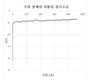
도 10은 Ag/AgCl 기준 전극 대비 4 V의 일정한 전위를 인가하여 용액으로부터 리튬을 침착시키는 또 다른 실행에 대한 전류 대 시간 플롯을 보여준다. 이러한 전압은 도 9의 전압전류도에서 관찰된 도금 전압을 관찰한 후 선택되었다.
도 11은 도 10의 전류 대 시간 플롯을 수득하기 위해 수행된 전기침착 실험의 결과의 광학 사진을 보여준다. 왼쪽 스트립은 실험 전의 구리 캐소드 기판을 보여준다. 오른쪽 스트립은 전기침착 공정이 수행된 후 구리 캐소드 기판 상에 침착된 리튬 금속을 보여준다.
도 12는 리튬-이온만이 리튬 염수 상으로부터 용매 상의 리튬 염으로 전달될 수 있게 하여 캐소드 기판 상에 전기침착될 수 있게 하는 양이온 교환 멤브레인에 의해 보조된, 염수로부터 직접 리튬 금속을 침착시키는 것을 가능하게 하는 실시양태 중 하나의 개략도를 보여준다.
도 13은 도 12에 도식화된 기본형 셀에서 수행된 리튬 금속 도금 실험에 대한 주기적 전압전류도를 보여준다.
도 14는 리튬 추출과 전기도금을 동시에 수행하는 공정을 도시한다.
도 15a 및 15b는 셀 설계도를 포함하여, 동시 수행되는 리튬 추출 및 전기도금을 준비하기 위한 시연 장치를 도시한다.
도 16은 샌드위치된 액체 멤브레인을 포함하는 셀 공정을 도시한다.
도 17은 수성 염수로부터의 리튬의 지속적인 연속 R2R 제조를 위한 처리 셀의 개략도를 보여준다.
도 18은 유기 용액 매질로부터 리튬 금속 막을 이동하는 Cu 호일 상에 침착시키기 위한 처리 셀의 개략도를 보여준다.
도 19는 전기도금 셀의 디자인 구조를 보여준다.So that the features, advantages and objects of the disclosure, as well as others that may become apparent, may be achieved and more particularly understood, the invention, briefly summarized above, may be described with reference to embodiments thereof, which are illustrated in the accompanying drawings that form a part of this specification. It is to be borne in mind, however, that the drawings illustrate only illustrative embodiments of the invention and are therefore not to be considered limiting of its scope, for the invention may admit to other equally effective embodiments.
Figure 1 schematically illustrates one embodiment of the disclosed method for obtaining lithium metal directly from a lithium brine solution via a combined approach of solvent extraction and electrowinning.
Figure 2 shows a schematic diagram of an electrochemical cell used in an electrowinning process for plating lithium metal directly onto a cathode substrate from a solution consisting of a lithium salt in a solvent.
Figure 3 shows an optical photograph of the basic three-electrode cell schematically illustrated in Figure 2.
Figure 4 shows an optical photograph of the interior of the three-electrode cell shown in Figure 3.
Figure 5 shows an optical photograph of the overall basic device configuration to support the concept. The device configuration consists of a three-electrode cell connected to a potentiometer to control the electrochemical parameters during the lithium electrowinning process.
Figure 6 shows the voltammograms (or current-voltage curves) obtained during the electrodeposition of lithium metal onto a copper cathode in an electrochemical cell containing a 1 M LiPF 6 -DEC solution as an electrolyte. Here, DEC is a solvent that dissolves LiPF 6 lithium salt, which has low water miscibility (<4 wt%).
Figure 7 shows a voltammogram for lithium metal electrodeposition at a fixed voltage and the resulting lithium metal deposited on a copper-plated platinum cathode in an electrochemical cell.
Figure 8 shows the electrochemical cell of Figure 3 after lithium metal has been electrodeposited on a copper substrate.
Figure 9 shows the voltammograms (current versus voltage curves) obtained during the electrodeposition of lithium on a copper substrate. The lithium salt used during these measurements was LiPF 6 and the solvent was diethylene carbonate. The concentration of the salt in the solvent was 1 M LiPF 6 in DEC. This salt solution in solvent was used for demonstration purposes.
Figure 10 shows a current versus time plot for another run of lithium deposition from solution at a constant potential of 4 V versus a Ag/AgCl reference electrode. This voltage was chosen after observing the plating voltages observed in the voltammogram of Figure 9.
Figure 11 shows an optical photograph of the results of an electrodeposition experiment performed to obtain the current versus time plot of Figure 10. The left strip shows the copper cathode substrate before the experiment. The right strip shows lithium metal deposited on the copper cathode substrate after the electrodeposition process.
Figure 12 shows a schematic diagram of one embodiment enabling the deposition of lithium metal directly from a brine, assisted by a cation exchange membrane that allows only lithium ions to transfer from the lithium brine phase to the lithium salt in the solvent phase, where they can then be electrodeposited on the cathode substrate.
Figure 13 shows a cyclic voltammogram for a lithium metal plating experiment performed on the basic cell schematically illustrated in Figure 12.
Figure 14 illustrates a process for performing lithium extraction and electroplating simultaneously.
Figures 15a and 15b illustrate a demonstration device for preparing simultaneous lithium extraction and electroplating, including a cell schematic.
Figure 16 illustrates a cell process including a sandwiched liquid membrane.
Figure 17 shows a schematic diagram of a processing cell for continuous R2R production of lithium from aqueous brine.
Figure 18 shows a schematic diagram of a treatment cell for depositing a lithium metal film on a Cu foil moving from an organic solution medium.
Figure 19 shows the design structure of the electroplating cell.
실시양태의 상세한 설명Detailed description of the embodiment
본 개시내용의 방법 및 시스템은 이제 실시양태를 도시하는 첨부 도면을 참조하여 이하에서 더 자세히 설명될 수 있다. 본 개시내용의 방법 및 시스템은 많은 다양한 형태를 가질 수 있고, 본원에 제시된, 예시된 실시양태로 제한되는 것으로 해석되어서는 안 되며; 더 정확히 말하자면, 이러한 실시양태는 본 개시내용이 완벽하고 완전하도록 하고 관련 기술분야의 통상의 기술자에게 그 범위를 충분히 전달할 수 있도록 하기 위해 제공된다. 동일한 번호는 전체에 걸쳐 동일한 요소를 나타낸다.The method and system of the present disclosure will now be described in more detail hereinafter with reference to the accompanying drawings which illustrate embodiments. The method and system of the present disclosure may take many different forms and should not be construed as limited to the illustrative embodiments set forth herein; rather, these embodiments are provided so that this disclosure will be thorough and complete, and will fully convey the scope of the disclosure to those skilled in the art. Like numbers represent like elements throughout.
염수로부터의 직접 리튬 추출 (DLE)은 어려운 과제이다. 지구 상에서 가장 풍부한 리튬 염수 자원, 예컨대 남미 "리튬 삼각지대" (아르헨티나-볼리비아-칠레)의 리튬 염수 자원은 높은 총 용존 고체 수준을 갖는 농축된 염수이다. 이러한 리튬 염수는 양이온 (주로 Li+, Na+, K+, Mg2+, Ca2+, B+ 및 H+)의 염 및 음이온 (주로 Cl-, SO4 2-, 및 OH-)의 염을 함유하는 거의 포화된 혼합 염 용액이다. 대부분의 직접 리튬 추출 기술은 흡착제로부터 리튬을 용출하거나 리튬 선택적 용매로부터 리튬을 스트리핑하기 위해 담수를 사용한다. 그러나, 직접 리튬 추출이 실시되는 지역은 극도로 건조하여 이를 적용하기 더 어렵다.Direct lithium extraction (DLE) from brine is a challenging task. The most abundant lithium brine resources on Earth, such as those in the South American "lithium triangle" (Argentina-Bolivia-Chile), are concentrated brine with high total dissolved solids levels. These lithium brines are nearly saturated mixed salt solutions containing salts of cations (primarily Li + , Na + , K + , Mg2 + , Ca2 + , B +, and H + ) and salts of anions (primarily Cl- , SO42- , and OH- ) . Most direct lithium extraction technologies use fresh water to leach lithium from adsorbents or to strip lithium from lithium-selective solvents. However, the regions where direct lithium extraction is performed are extremely dry, making it more difficult to apply.
미래의 고용량 배터리는 리튬 금속 애노드를 사용할 것으로 예상되기 때문에 리튬 금속에 대한 수요가 많을 것으로 예상된다. 현재 전 세계 리튬 금속 생산량은 매우 적어서, 수요와 공급 사이의 격차가 클 것으로 예상된다. 본 개시내용은 담수를 사용하지 않는, 신규한, 비용이 현저히 절감된 리튬 금속 제조 방안을 제시한다. 이는 도 1에 도시된 바와 같은 신규한 전기침착 (ED) 방안과 통합된 용매 추출 (SE)에 의해 달성된다.The demand for lithium metal is expected to be high because future high-capacity batteries are expected to use lithium metal anodes. The current global lithium metal production is very small, and the gap between demand and supply is expected to be large. The present disclosure proposes a novel, significantly reduced cost method for producing lithium metal without using fresh water. This is achieved by solvent extraction (SE) integrated with a novel electrodeposition (ED) method as illustrated in FIG. 1.
리튬 금속을 리튬 염수로부터 직접 제조하는 개시된 방법에서, 염수 중 리튬-이온은 용매 추출 또는 멤브레인-보조 용매 추출에 의해 첨가된 용매 매질로 선택적으로 추출된다. 이어서 리튬-이온은 전해채취로서 공지된 공정에서 최종 리튬 함침된 유기 또는 무기 용매 매질로부터 전자 전도성 기판 상에 전기화학적으로 침착된다. 이러한 공정은 또한 유기 또는 무기 용매 매질로부터 리튬 금속이 전자 전도성 기판 상에 전해채취되기 전에 일련의 용매 추출 단계에 의해 수행될 수 있다. 리튬을 전기침착시키는 데 사용할 수 있는 리튬 염은 LiCl, LiClO4, Li2SO4, 또는 LiPF6을 포함하지만 이로 제한되지 않는다. 리튬 염수를 출발 물질로 하는 전체 공정에 의해 침착된 리튬의 최종 순도는 80 내지 99.99%의 범위일 수 있다. 출발 물질인 농축된 염수 용액으로부터 도금된 리튬 금속의 최종 두께는 1 nm 내지 5 mm의 범위일 수 있다. 용매는 개시된 공정에 통합될 수 있도록 몇 가지 주요 특징을 가져야 한다: (1) 용매는 용존 Li-이온/염을 고도로 가용화하거나 수성 염수로부터 선택적으로 추출할 수 있다; (2) 용매는 Li 금속의 캐소드 침착을 허용한다; (3) 용매는 전기화학 셀에서 처리 동안 애노드 반응성 열화를 견딜 수 있는 장기 안정성을 갖는다; (4) 용매는 물에 대해 비혼화성이어야 한다. 멤브레인-보조 용매 추출의 경우, 멤브레인은 리튬을 염수로부터 첨가된 용매로 선택적으로 투과할 것이다.In the disclosed method for producing lithium metal directly from a lithium brine, lithium ions in the brine are selectively extracted into an added solvent medium by solvent extraction or membrane-assisted solvent extraction. The lithium ions are then electrochemically deposited on an electron-conducting substrate from the final lithium-impregnated organic or inorganic solvent medium in a process known as electrowinning. The process may also be performed by a series of solvent extraction steps before the lithium metal is electrowinning from the organic or inorganic solvent medium onto the electron-conducting substrate. Lithium salts that can be used to electrodeposit lithium include, but are not limited to, LiCl, LiClO 4 , Li 2 SO 4 , or LiPF 6 . The final purity of the lithium deposited by the overall process starting from a lithium brine can range from 80 to 99.99%. The final thickness of the lithium metal plated from the starting concentrated brine solution can range from 1 nm to 5 mm. The solvent must have several key characteristics to be integrated into the disclosed process: (1) the solvent must be highly solubilizing or selectively extractable from the aqueous brine of dissolved Li ions/salts; (2) the solvent must allow for cathodic deposition of Li metal; (3) the solvent must have long-term stability to withstand anode reactivity degradation during processing in the electrochemical cell; and (4) the solvent must be immiscible with water. In the case of membrane-assisted solvent extraction, the membrane will selectively permeate lithium from the brine into the added solvent.
상기 공정에서 수득된 리튬 금속 생성물은 금속 리튬이 적어도 하나의 전극으로서의 역할을 하는 1차 또는 2차 배터리에서 애노드 재료로서의 역할을 하도록 추가로 정제될 수 있다. 이러한 배터리 화학에서 이러한 공정을 통해, 리튬-산소 배터리, 리튬-황 배터리, 리튬-이온 삽입 캐소드를 갖는 충전식 리튬 금속 배터리, 리튬-MnO2 1차 배터리, 및 용매화된 리튬-이온 전도성 염을 갖는 액체 전해질과 달리 고체-상태 리튬-이온 전도체를 전해질로서 포함하는 고체-상태 리튬 금속 배터리를 포함하지만 이로 제한되지 않는 배터리를 위한 실행 가능한 금속 리튬 금속 전극이 제조될 수 있다.The lithium metal product obtained in the above process can be further purified to serve as an anode material in primary or secondary batteries in which metallic lithium serves as at least one electrode. In such battery chemistries, viable metallic lithium metal electrodes can be prepared for batteries including but not limited to lithium-oxygen batteries, lithium-sulfur batteries, rechargeable lithium metal batteries having lithium-ion insertion cathodes, lithium-MnO 2 primary batteries, and solid-state lithium metal batteries comprising a solid-state lithium-ion conductor as the electrolyte as opposed to a liquid electrolyte having a solvated lithium-ion conducting salt.
배터리-등급 리튬 금속은 리튬 금속 주괴가 용융 염 전해에 의해 제조된 후 2차 배터리 작동에 필요한 >99.8% 순도의 리튬 금속을 수득하는 추가적인 정제 및 2차 배터리에 사용될 리튬 금속 전극의 제작을 위한 추가적인 단계를 필요로 한다. 개시된 기술은 정제 단계 및 전극 제작 단계를 회피하여 전극 형태의 배터리-등급 리튬 금속을 직접 제조하게 할 수 있다. 개시된 방법에 의해 제작된 리튬 금속 전극은 1 nm 내지 5 mm일 수 있다. 이러한 공정은 롤투롤(roll-to-roll) 방식으로 수행되어, 리튬 금속 2차 배터리의 상업적 제작에 사용되기 위한 구리 전극 상에 도금된 리튬 금속 롤을 전체 상업적 규모로 제조하게 할 수 있어서, 공정 단계 개수를 제한하고 관련 배터리 화학을 위한 리튬 금속 전극의 제조 비용을 추가로 절감할 수 있다.Battery-grade lithium metal requires additional steps of purification after lithium metal ingot is prepared by molten salt electrolysis to obtain lithium metal with purity >99.8% necessary for secondary battery operation, and further steps for fabrication of lithium metal electrodes to be used in secondary batteries. The disclosed technology can avoid the purification steps and electrode fabrication steps to directly produce battery-grade lithium metal in the form of electrodes. The lithium metal electrodes prepared by the disclosed method can have a size of 1 nm to 5 mm. The process can be performed in a roll-to-roll manner to produce full commercial-scale rolls of lithium metal plated on copper electrodes for use in the commercial fabrication of lithium metal secondary batteries, thereby limiting the number of process steps and further reducing the cost of manufacturing lithium metal electrodes for relevant battery chemistries.
A. 분리를 실시하기 위한 장치A. Device for performing separation
도 14는 리튬 막을 생성하기 위한 솔보-전기-침착(solvo-electro-deposition) 공정(100)을 도시한다. 한 실시양태에서, 솔보-전기-침착 공정(100)은 수성 염수(102)를 제공하는 단계, 순수한 Li-함유 수용액 (예를 들어, LiCl (염화리튬))(104A)을 생성하는 단계, 유기 용액 매질(104B)로부터 리튬을 전기침착시키는 단계 (예를 들어, 멤브레인-보조), Li-금속 막 침착물(106) (예를 들어, 배터리 애노드를 위한 것)을 생성하는 단계를 포함할 수 있다. 대안적인 관련 실시양태에서, 솔보-전기-침착 공정(100)은 수성 염수(102)를 제공하는 단계, 유기 용액 매질(104C)로부터 직접 리튬을 전기침착시키는 단계 (예를 들어, 멤브레인-보조), 및 어두운 회색 Li-금속 막 침착물(106) (예를 들어, 배터리 애노드를 위한 것)을 생성하는 단계를 포함할 수 있다.FIG. 14 illustrates a solvo-electro-deposition process (100) for forming a lithium membrane. In one embodiment, the solvo-electro-deposition process (100) can include providing an aqueous brine (102), forming a pure Li-containing aqueous solution (e.g., LiCl (lithium chloride)) (104A), electrodepositing lithium from an organic solution medium (104B) (e.g., membrane-assisted), and forming a Li-metal membrane deposit (106) (e.g., for a battery anode). In an alternative related embodiment, the solvo-electro-deposition process (100) can include the steps of providing an aqueous brine (102), electrodepositing lithium directly from an organic solution medium (104C) (e.g., membrane-assisted), and producing a dark gray Li-metal film deposit (106) (e.g., for a battery anode).
도 14와 관련하여, 도 15a 및 15b는 도 14에 도시된 한 실시양태와 관련하여 사용되기 위한 배치-셀 시스템(120)을 보여준다. 도 15a는, 도 14와 연관된 실시양태와 관련하여, 리튬 추출 및 전기침착을 동시에 수행하기 위한 처리 셀 (예를 들어, 배치 셀) 시스템(120) 및 관련 솔보-전기-침착 공정(100)의 실험실-시연 버전의 사진 표현이다. 도 15b는 달리 도 15a에 나와 있는 배치-셀 시스템의 그래픽 표현이다. 배치-셀 시스템(120)은 셀 격납 유닛(122) (예를 들어, 액체 전해질을 포함할 수 있고, 예를 들어, 전극 및/또는 멤브레인을 보유할 수 있는 용기), 작업 전극(124) (예를 들어, 예를 들어 구리 또는 또 다른 금속으로 만들어진 캐소드), 상대 전극(126) (예를 들어, 예를 들어 혼합 금속 산화물 (MMO) 또는 백금 (Pt)으로 만들어진 애노드), 기준 전극(128) (예를 들어, 기준 전도도의 측정을 돕기 위한 것), 및 금속 호일(130) (예를 들어, 구리로 만들어진 것)을 포함할 수 있다. 전기침착 시, 생성된 복합 금속 호일(130A)은 기본 금속 호일(130) 및 리튬 층(132)을 포함할 수 있다. 도 15b에서 추가로 볼 수 있는 바와 같이, 처리 셀 (예를 들어, 배치 셀) 시스템(120)은 멤브레인(134) (예를 들어, CEM 또는 선택적 양이온 교환 멤브레인 (sCEM)); 및 Li+-함유 수성 염수 (예를 들어, 저장 탱크/컨테이너, 호수, 연못, 및/또는 우물로부터 유래된 것)를 보유하는 애노드 챔버(136) 및 Li-X (염) 용매 유기 용액 매질을 보유하는 캐소드 챔버(138)를 추가로 포함할 수 있다. 한 실시양태에서, 애노드 챔버(136) 및 캐소드 챔버(138)의 각각의 경계는 적어도 부분적으로 셀 격납 유닛(122) 및 멤브레인(134)에 의해 규정될 수 있다. 한 실시양태에서, 멤브레인(134)은 작업 전극(124)과 상대 전극(126) 사이에 위치할 수 있다. 상대 전극(326) 및 작업 전극(324)은 리튬-함유 유기 용액 (예를 들어, 캐소드 챔버(138) 내에 있는 것)을 통해/으로 연장된 금속 호일(330/330A) 상에의 리튬의 전기침착을 구동하는 방식으로 충전되도록 구성될 수 있다. 한 실시양태에서, 처리 셀(120)은 갈바니 셀을 규정할 수 있다. 한 실시양태에서, 상대 전극(126)은 애노드 챔버(136)에서 Li+-함유 수성 염수와 접촉할 수 있고, 작업 전극(124)은 캐소드 챔버(138)에서 리튬-보유 유기 용액과 접촉할 수 있다. 한 실시양태에서, 셀 격납 유닛(122)은 하우징 및/또는 컨테이너로서 규정될 수 있다.In connection with FIG. 14 , FIGS. 15a and 15b illustrate a batch-cell system (120) for use in connection with one embodiment depicted in FIG. 14 . FIG. 15a is a photographic representation of a laboratory-demonstration version of a processing cell (e.g., batch cell) system (120) and associated solvo-electro-deposition process (100) for performing simultaneous lithium extraction and electrodeposition, in connection with the embodiment associated with FIG. 14 . FIG. 15b is a graphical representation of the batch-cell system shown in FIG. 15a . A batch-cell system (120) can include a cell containment unit (122) (e.g., a vessel that can include a liquid electrolyte and can hold, for example, electrodes and/or membranes), a working electrode (124) (e.g., a cathode made of, for example, copper or another metal), a counter electrode (126) (e.g., an anode made of, for example, mixed metal oxide (MMO) or platinum (Pt)), a reference electrode (128) (e.g., to aid in measuring a reference conductivity), and a metal foil (130) (e.g., made of copper). During electrodeposition, the resulting composite metal foil (130A) can include the base metal foil (130) and the lithium layer (132). As further shown in FIG. 15b, the treatment cell (e.g., batch cell) system (120) can further include an anode chamber (136) containing a membrane (134) (e.g., a CEM or selective cation exchange membrane (sCEM)); and a Li + -containing aqueous brine (e.g., derived from a storage tank/container, a lake, a pond, and/or a well) and a cathode chamber (138) containing a Li-X (salt) solvent organic solution medium. In one embodiment, the respective boundaries of the anode chamber (136) and the cathode chamber (138) can be defined at least in part by the cell containment unit (122) and the membrane (134). In one embodiment, the membrane (134) can be positioned between the working electrode (124) and the counter electrode (126). The counter electrode (326) and the working electrode (324) can be configured to be charged in a manner that drives the electrodeposition of lithium onto the metal foil (330/330A) extending through/into a lithium-containing organic solution (e.g., within the cathode chamber (138)). In one embodiment, the treatment cell (120) can define a galvanic cell. In one embodiment, the counter electrode (126) can be in contact with the Li + -containing aqueous brine in the anode chamber (136), and the working electrode (124) can be in contact with the lithium-containing organic solution in the cathode chamber (138). In one embodiment, the cell containment unit (122) can be defined as a housing and/or container.
도 15b는 Li 금속 층(132) (유기 용매 Li-X 용액으로부터 유래된 것)이 플레이트 또는 호일 캐소드(130) (예를 들어, 구리) 상에 전기침착되게 할 수 있으면서 이와 동시에 캐소드 챔버(138)의 유기 용액 매질 (예를 들어, 리튬-함유 유기 전해질 용액)이 애노드 챔버(136)의 수용액 또는 염수로부터 리튬을 추출하게 할 수 있는 도 14의 배치 셀 공정의 실험실 시연 예를 도시한다. Li+-전도성 또는 Li+-선택적 멤브레인(134)은 유기 용액과 수용액 사이의 중앙에 배치될 수 있다 (도 15b 참조). 이러한 추출-전기침착 셀(120)은 셀 격납 유닛(122) 및 중간 멤브레인(134)에 의해 규정된 두 개의 챔버(136, 138)를 갖도록 구성될 수 있다. 한 챔버(136)는 수성 염수 용액을 포함할 수 있고, 다른 챔버(138)는 유기 용액을 포함할 수 있다. 또한, 각각의 용액은, 필요에 따라, 외부 저장 탱크 및/또는 자연적 공급원 (예를 들어, 호수, 연못, 대수층, 및/또는 우물)으로부터 각각 보충될 수 있으며, 도 14에 나와 있는 호수(102)가 이러한 보충 공급원의 한 예이다. 도 15a 및 15b의 공정(100)은 단일-유닛 처리 셀(120)에서의 솔보-전기 추출-전기침착 공정인 것으로 간주될 수 있다. 셀 치수, 구성, 및 용액 종류 (염수 및 유기 용액)에 따라, 2-전극 전기침착을 위한 전류 밀도는 멤브레인 또는 캐소드 표면적 1 cm2당 0.1-100 mA의 범위일 수 있다. 고정 전류 전기침착 동안, 작동 전압은 0 내지 10 볼트일 수 있다 (이는 Ag/AgCl (KCl) 기준 전극 대비 ~3.2 V의 Li 환원 전위 및 IR 강하를 포함함).FIG. 15b illustrates a laboratory demonstration example of the batch cell process of FIG. 14 in which a Li metal layer (132) (from an organic solvent Li-X solution) can be electrodeposited on a plate or foil cathode (130) (e.g., copper) while at the same time allowing an organic solution medium (e.g., a lithium-containing organic electrolyte solution) in the cathode chamber (138) to extract lithium from an aqueous solution or brine in the anode chamber (136). A Li+-conductive or Li+-selective membrane (134) can be positioned centrally between the organic and aqueous solutions (see FIG. 15b ). Such an extraction-electrodeposition cell (120) can be configured to have two chambers (136, 138) defined by a cell containment unit (122) and an intermediate membrane (134). One chamber (136) may contain an aqueous brine solution, and the other chamber (138) may contain an organic solution. Additionally, each solution may be replenished, as needed, from an external storage tank and/or a natural source (e.g., a lake, pond, aquifer, and/or well), the lake (102) illustrated in FIG. 14 being one example of such a replenishment source. The process (100) of FIGS. 15a and 15b may be considered a solvo-electroextraction-electrodeposition process in a single-unit treatment cell (120). Depending on the cell dimensions, configuration, and solution type (brine and organic solution), the current density for the two-electrode electrodeposition may range from 0.1-100 mA per cm 2 of membrane or cathode surface area. During fixed current electrodeposition, the operating voltage can be between 0 and 10 V (which includes the Li reduction potential and IR drop of ~3.2 V vs. Ag/AgCl (KCl) reference electrode).
도 16은 본 개시내용의 실시양태에 따른 파생 셀 구성을 도시한다. 일반적으로 처리 셀(220)로서 표지된 파생 셀 구성은 셀 격납 유닛(222), 작업 전극(224) (예를 들어, 예를 들어 구리 또는 또 다른 금속으로 만들어진 캐소드), 상대 전극(226) (예를 들어, 예를 들어 혼합 금속 산화물 (MMO) 또는 백금 (Pt)으로 만들어진 애노드), 기준 전극(228), 복합 금속 호일(230A) (예를 들어, 구리로 만들어지고 리튬 층으로 코팅됨), Li-X 용매 액체 멤브레인 (234) (예를 들어, 한 쌍의 CEM 및 중간 용매 구역 (개별적으로 표지되지 않음)을 포함함), Li+-함유 수성 염수를 보유하는 애노드 챔버(236), 및 Li-X 용매 유기 용액 매질을 보유하는 캐소드 챔버(238)를 포함할 수 있다. 본 개시내용의 전체에 걸쳐, 유사한 번호가 매겨진 구성요소들 (예를 들어, 120, 220, 320, 및 420; 124, 224, 324, 및 424 등)은, 주어진 실시양태와 상반되는 내용이 구체적으로 언급되지 않는 한, 기능 및/또는 디자인에 있어 유사할 것으로 예상될 수 있다는 것을 이해해야 한다.FIG. 16 illustrates a derivative cell configuration according to an embodiment of the present disclosure. The derivative cell configuration, generally labeled as a processing cell (220), can include a cell containment unit (222), a working electrode (224) (e.g., a cathode made of, for example, copper or another metal), a counter electrode (226) (e.g., an anode made of, for example, mixed metal oxide (MMO) or platinum (Pt)), a reference electrode (228), a composite metal foil (230A) (e.g., made of copper and coated with a lithium layer), a Li-X solvent liquid membrane (234) (e.g., comprising a pair of CEMs and an intermediate solvent zone (not individually labeled)), an anode chamber (236) holding a Li+-containing aqueous brine, and a cathode chamber (238) holding a Li-X solvent organic solution medium. It should be understood that throughout this disclosure, like-numbered components (e.g., 120, 220, 320, and 420; 124, 224, 324, and 424, etc.) can be expected to be similar in function and/or design, unless specifically stated otherwise in a given embodiment.
도 15b와 도 16을 비교할 때, 도 15b의 2-챔버 셀(120) 내의 중앙 멤브레인(134) (CEM 또는 선택적 CEM)은 도 16에 도시된 바와 같은 샌드위치된 액체 멤브레인 또는 액체 챔버(234)로 대체될 수 있다. 샌드위치된 액체 멤브레인(234)은 두 개의 고체 Li-전도성 멤브레인 또는 CEM (개별적으로 표지되지 않은 구성요소) 들로 샌드위치된 Li-X 용매를 포함할 수 있다. 액체 멤브레인(234)은 애노드 챔버(236)의 수용액으로부터 캐소드 챔버(238)의 유기 용액으로의 투과를 위한 Li+ 선택성을 제공할 수 있다. 따라서, 도 16은 샌드위치된 액체 멤브레인(234)을 활용하여 Li 이온을 애노드 챔버(236)의 수성 염수로부터 캐소드 챔버(238)의 유기 용액 매질로 선택적으로 수송할 수 있는 단일-유닛 배치에서의 솔보-전기 추출-전기침착 공정을 위한 처리 셀(220)을 도시한다. 중앙 챔버 내의 액체가 탈수 칼럼의 외부 루프를 통해 액체 멤브레인(234)을 재순환하는 경우, 액체 멤브레인 (또는 챔버)은 수성 염수 챔버로부터 유기 용액 챔버로의 물 분자의 수송을 차단하는 (반면에 Li의 전달을 허용하는) 장벽으로서의 역할을 할 수 있다. 이는 추출과 침착을 동시에 수행하는 지속적인 작업에 도움이 될 것이다.Comparing FIGS. 15b and 16, the central membrane (134) (CEM or optional CEM) within the two-chamber cell (120) of FIG. 15b can be replaced with a sandwiched liquid membrane or liquid chamber (234) as shown in FIG. 16. The sandwiched liquid membrane (234) can comprise a Li-X solvent sandwiched between two solid Li-conducting membranes or CEMs (components not individually labeled). The liquid membrane (234) can provide Li + selectivity for permeation from the aqueous solution in the anode chamber (236) to the organic solution in the cathode chamber (238). Thus, FIG. 16 illustrates a treatment cell (220) for a solvo-electroextraction-electrodeposition process in a single-unit configuration that can selectively transport Li ions from the aqueous brine in the anode chamber (236) to the organic solution medium in the cathode chamber (238) by utilizing sandwiched liquid membranes (234). When the liquid in the central chamber recirculates the liquid membrane (234) through the outer loop of the dehydration column, the liquid membrane (or chamber) can act as a barrier to block the transport of water molecules from the aqueous brine chamber to the organic solution chamber (while allowing the transport of Li). This will aid in continuous operation where extraction and deposition are performed simultaneously.
도 17은, 예를 들어, 롤투롤 (R2R) 설비를 사용하여, 리튬을 수성 염수로부터 추출하는 동안 Li 금속 막 침착물을 기판 호일 (예를 들어, 구리 호일 또는 다른 금속 막 또는 웹) 상에 산업적으로 대량 연속 제조하는 데 도움이 되는 처리 셀(320)의 실시양태를 도시한다. 도 17에 도시된 바와 같이, 처리 셀(320)은 셀 격납 유닛(322) (예를 들어, 액체 전해질을 포함할 수 있고, 예를 들어, 전극 및/또는 멤브레인을 보유할 수 있는 용기), 작업 전극(324) (예를 들어, 예를 들어 구리 또는 또 다른 금속으로 만들어진 캐소드), 상대 전극(326) (예를 들어, 예를 들어 혼합 금속 산화물 (MMO) 또는 백금 (Pt)으로 만들어진 애노드), 기준 전극(328) (예를 들어, 통상적으로 캐소드 표면에 가까이 (수 밀리미터 이내에) 위치함), 금속 호일(330) (예를 들어, 구리 호일), 복합 금속 호일(330A) (예를 들어, 리튬 층으로 코팅된 구리로 만들어짐), 멤브레인(334) (예를 들어, CEM 또는 sCEM), Li+-함유 수성 염수를 보유하는 애노드 챔버(336), 애노드 챔버(336)에 사용되는 염수 공급원(336A) (예를 들어, 호수, 우물, 대수층, 및/또는 저장 컨테이너), Li-X 용매 유기 용액 매질을 보유하는 캐소드 챔버(338), 투입/공급 호일 롤(340A), 생성물 호일 롤(340B) (예를 들어, 리튬-코팅 구리 호일), 불활성 기체 (예를 들어, 아르곤(Ar))로 채워진 저장 탱크(342) (예를 들어, 생성물 호일 롤(340B)을 가질 수 있음), 및 탈수 칼럼(344) (예를 들어, 제올라이트 탈수 칼럼 베드)을 포함할 수 있다. 실시양태에서, 멤브레인(334)은 작업 전극(324)과 상대 전극(326) 사이에 위치할 수 있다. 상대 전극(326) 및 작업 전극(324)은 리튬-함유 유기 용액을 통해 연장된 금속 호일(330/330A) 상에의 리튬의 전기침착을 구동하는 방식으로 충전되도록 구성될 수 있다. 처리 셀(320)은, 필요에 따라, 유체 이동/보충 및/또는 호일 이동을 용이하게 하기 위해 연결 도관 및/또는 하나 이상의 추가적인 중간 롤러 (도시되어 있지만 표지되지 않음)를 추가로 포함할 수 있다.FIG. 17 illustrates an embodiment of a processing cell (320) that aids in the industrial mass continuous production of Li metal film deposits on a substrate foil (e.g., copper foil or other metal film or web) while extracting lithium from an aqueous brine, for example, using a roll-to-roll (R2R) facility. As illustrated in FIG. 17, the treatment cell (320) comprises a cell containment unit (322) (e.g., a vessel that may contain a liquid electrolyte and may hold, for example, electrodes and/or membranes), a working electrode (324) (e.g., a cathode made of, for example, copper or another metal), a counter electrode (326) (e.g., an anode made of, for example, mixed metal oxide (MMO) or platinum (Pt)), a reference electrode (328) (e.g., typically positioned close to (within a few millimeters) the cathode surface), a metal foil (330) (e.g., copper foil), a composite metal foil (330A) (e.g., made of copper coated with a lithium layer), a membrane (334) (e.g., a CEM or sCEM), an anode chamber (336) containing a Li + -containing aqueous brine, a brine source (336A) used in the anode chamber (336) (e.g., a The cell may include a cathode chamber (338) holding a Li-X solvent organic solution medium (e.g., a lake, a well, an aquifer, and/or a storage container), an input/feed foil roll (340A), a product foil roll (340B) (e.g., lithium-coated copper foil), a storage tank (342) (e.g., which may have the product foil roll (340B)) filled with an inert gas (e.g., argon (Ar)), and a dehydration column (344) (e.g., a zeolite dehydration column bed). In embodiments, the membrane (334) may be positioned between the working electrode (324) and the counter electrode (326). The counter electrode (326) and the working electrode (324) may be configured to be charged in a manner that drives the electrodeposition of lithium onto the extended metal foil (330/330A) through the lithium-containing organic solution. The processing cell (320) may additionally include connecting conduits and/or one or more additional intermediate rollers (illustrated but not labeled) to facilitate fluid movement/replenishment and/or foil movement, as desired.
도 17의 롤투롤 처리 셀(320)은 연속 다단계 침착 공정을 용이하게 할 수 있다. 제1 단계에서, 애노드 챔버(336) 내의 수성 염수 용액은, 필요에 따라, Li+를 연속적으로 제공하기 위해 외부 공급원 또는 저장소(336A)로부터 보충될 수 있다. 제2 단계에서, Li+는 멤브레인(334)을 통해 수성 상으로부터 유기 상으로 연속적으로 전달될 수 있다. 제3 단계에서, Cu 호일 웹(330, 330A)이 전기침착 구역을 통해 연속적으로 이동하는 동안, 이동하는 구리 캐소드(324) (예를 들어, 공급 호일 롤(340A)로부터 공급된 구리 호일(330)의 형태를 가짐) 상에의 Li 금속의 전기침착이 캐소드 (예를 들어, 유기 용액) 챔버(338)에서 발생할 수 있다. 유기 상의 물 함량 수준은 탈수 칼럼(344) 및 관련 재순환 루프에 의해 제어될 수 있다. 제4 단계에 따라, Li 금속-Cu 호일 웹(330A)의 생성물 롤(340B)은, 생성물 롤(340B)의 수집을 용이하게 하는 데 필요한 임의의 하드웨어와 함께 아르곤 (Ar) 기체 분위기 또는 또 다른 적합한 불활성 기체가 제공된 불활성 기체 챔버(342)에 보존 및/또는 저장될 수 있다.The roll-to-roll processing cell (320) of FIG. 17 can facilitate a continuous multi-step deposition process. In a first step, the aqueous brine solution within the anode chamber (336) can be replenished from an external source or reservoir (336A), as needed, to continuously provide Li + . In a second step, Li + can be continuously transferred from the aqueous phase to the organic phase through the membrane (334). In a third step, while the Cu foil web (330, 330A) is continuously moved through the electrodeposition zone, electrodeposition of Li metal onto a moving copper cathode (324) (e.g., in the form of copper foil (330) supplied from a supply foil roll (340A)) can occur in the cathode (e.g., organic solution) chamber (338). The water content level of the organic phase can be controlled by a dehydration column (344) and an associated recirculation loop. According to the fourth step, the product roll (340B) of Li metal-Cu foil web (330A) can be preserved and/or stored in an inert gas chamber (342) provided with an argon (Ar) gas atmosphere or another suitable inert gas, together with any hardware necessary to facilitate collection of the product roll (340B).
도 18은, 본 개시내용의 실시양태에 따라, 리튬 (Li) 금속 막을 유기 용액을 통해 이동하는 금속 (예를 들어, 구리) 호일 웹 상에 침착시키기 위한 롤투롤 (R2R) 캐소드 침착 공정을 도시한다. R2R 캐소드 침착 공정은 롤투롤 (R2R) 처리 셀(420)을 사용하여 달성될 수 있다. R2R 처리 셀(420)은 셀 격납 유닛(422), 작업 전극(424) (예를 들어, 예를 들어 구리 또는 또 다른 금속으로 만들어진 캐소드), 상대 전극(426) (예를 들어, 예를 들어 혼합 금속 산화물 (MMO) 또는 백금 (Pt)으로 만들어진 애노드), 금속 호일(430) (예를 들어, 구리 호일), 복합 금속 호일(430A) (예를 들어, 리튬 층으로 코팅된 구리로 만들어짐), Li-X 용매 유기 용액 매질을 보유하는 캐소드 챔버(438), 투입/공급 호일 롤(440A), 생성물 호일 롤(440B) (예를 들어, 리튬-코팅 구리 호일), 아르곤 (Ar) 기체로 채워진 저장 탱크(442) (예를 들어, 생성물 호일 롤(440B)을 가질 수 있음), 및 탈수 칼럼(444)을 포함할 수 있다. 상대 전극(426) (예를 들어, 애노드) 및 작업 전극(424) (예를 들어, 캐소드)는 리튬-함유 유기 용액을 통해 연장된 금속 호일(430/430A) 상에의 리튬의 전기침착을 구동하는 방식으로 충전되도록 구성될 수 있다. 도 17에 도시된 시스템(320)과 달리, 유기 Li-보유 용액이 염수 대신에 Li 공급원으로서의 역할을 하기 때문에, R2R 처리 셀(420)은 예를 들어 별도의 애노드 챔버 및/또는 멤브레인을 포함하지 않을 수 있다는 것을 유념하도록 한다. 그 대신에, 애노드(426) 및 캐소드(428) 둘 다가 동일한 챔버 (예를 들어, 438) 내에 포함됨으로써, 도 16의 시스템(320)에 비해 구조가 단순화된다.FIG. 18 illustrates a roll-to-roll (R2R) cathode deposition process for depositing a lithium (Li) metal film on a metal (e.g., copper) foil web moving through an organic solution, according to an embodiment of the present disclosure. The R2R cathode deposition process can be accomplished using a roll-to-roll (R2R) processing cell (420). An R2R processing cell (420) can include a cell containment unit (422), a working electrode (424) (e.g., a cathode made of, for example, copper or another metal), a counter electrode (426) (e.g., an anode made of, for example, mixed metal oxide (MMO) or platinum (Pt)), a metal foil (430) (e.g., copper foil), a composite metal foil (430A) (e.g., made of copper coated with a lithium layer), a cathode chamber (438) holding a Li-X solvent organic solution medium, an input/feed foil roll (440A), a product foil roll (440B) (e.g., lithium-coated copper foil), a storage tank (442) filled with argon (Ar) gas (e.g., which may have a product foil roll (440B)), and a dehydration column (444). The counter electrode (426) (e.g., anode) and the working electrode (424) (e.g., cathode) can be configured to be charged in such a way as to drive the electrodeposition of lithium onto the extended metal foil (430/430A) via the lithium-containing organic solution. Note that unlike the system (320) illustrated in FIG. 17, since the organic Li-containing solution serves as the Li source instead of brine, the R2R treatment cell (420) may not include, for example, a separate anode chamber and/or membrane. Instead, both the anode (426) and the cathode (428) are contained within the same chamber (e.g., 438), thereby simplifying the construction relative to the system (320) of FIG. 16.
더욱이, 도 18과 관련하여, 하나 이상의 리튬-함유 유기 용액이 Li 공급원으로서의 역할을 하는 경우, 롤투롤 (R2R) 처리 셀(420)을 사용하는 R2R 캐소드 침착 공정이 사용될 수 있으므로, 상기에 논의된 바와 같이 R2R 설비가 단순화될 수 있다. 이러한 경우, 이동하는 캐소드(424) (예를 들어, 금속 (예를 들어, Cu) 호일 웹(430); 및 복합 (예를 들어, Li-Cu) 호일 웹(430A))를 위한 전기침착 구역 (예를 들어, 438)을 위한 유기 용액의 물 함량은 침착된 Li 금속 (개별적으로 표지되지 않음)의 용해 속도를 최소화하도록 제어될 수 있다. 또한, 지속적인 연속 제조 동안 더 많은 Li-함유 유기 용액이 전기침착 탱크/챔버(438)에 연속적으로 공급될 수 있다. 유기 매질의 수명을 연장하기 위해 애노드 열화를 최소화하기 위해, 고정된 애노드(426)가 유기 용액 외부에 배치될 수 있고/있거나 애노드(426)가 하나 이상의 코팅 재료 (예컨대, LFP (리튬 철 인산염))로 개질될 수 있다. 또한, Li-X 염 용해도를 향상시키고 전기침착 성능을 개선하기 위해, 다른 첨가제 (예를 들어, 이온성 액체)가 유기 상에 첨가되거나 달리 활용될 수 있다. 예를 들어, 액체 Li 금속 전기침착 및 캐소드 주위에서의 회수를 가능하게 하기 위해, 이온성 액체 (유기 상)는 180℃ (즉, Li 금속의 융점)보다 약간 더 높은 온도로 가열될 수 있다.Moreover, with respect to FIG. 18, where one or more lithium-containing organic solutions serve as the Li source, a R2R cathode deposition process using a roll-to-roll (R2R) processing cell (420) may be utilized, thereby simplifying the R2R setup as discussed above. In such a case, the water content of the organic solution for the electrodeposition zone (e.g., 438) for the moving cathode (424) (e.g., metal (e.g., Cu) foil web (430); and composite (e.g., Li-Cu) foil web (430A)) may be controlled to minimize the dissolution rate of the deposited Li metal (not individually labeled). Additionally, more Li-containing organic solution may be continuously fed to the electrodeposition tank/chamber (438) during continued continuous manufacturing. To minimize anode degradation and extend the life of the organic medium, the immobilized anode (426) may be positioned outside of the organic solution and/or the anode (426) may be modified with one or more coating materials (e.g., LFP (lithium iron phosphate)). Additionally, other additives (e.g., ionic liquids) may be added to or otherwise utilized in the organic phase to enhance Li-X salt solubility and improve electrodeposition performance. For example, to enable liquid Li metal electrodeposition and recovery around the cathode, the ionic liquid (organic phase) may be heated to a temperature slightly above 180° C. (i.e., the melting point of Li metal).
실시양태에서, 구동되는 구리 웹의 선형 속도 (v), 인가되는 전기 침착 전류 (i), 침착되는 리튬 층의 너비 (w), 및 리튬 침착의 전류 효율 (η)은 하기 상관관계를 가질 수 있다:In an embodiment, the linear velocity of the driven copper web (v), the applied electrical deposition current (i), the width of the lithium layer being deposited (w), and the current efficiency of lithium deposition (η) can have the following relationships:
Q = iη/vw 식 1Q = iη/vw Equation 1
여기서 Q는 통과하는 총 전하이다. Q는 캐소드 표면 상에 침착되는 리튬 금속의 양과 관련이 있다. 예를 들어, 단일 양전하를 갖는 리튬의 경우, 각각의 전하는 단일 리튬 원자에 상응한다.Here, Q is the total charge passing through. Q is related to the amount of lithium metal deposited on the cathode surface. For example, in the case of lithium with a single positive charge, each charge corresponds to a single lithium atom.
전기침착 시간은 하기 식에 의해 정의될 수 있다:The electrochemical deposition time can be defined by the following equation:
t = η/vw 식 2t = η/vw Equation 2
배터리 애노드에 유용한 리튬 금속을 침착시키기 위해서는, 도금 전류 밀도 및 두께를 제어하는 것이 중요할 수 있다. 실시양태에서, 리튬 침착 속도는 0.2 mA/cm2 내지 0.8 mA/cm2의 범위의 전류 밀도 및 1 mAh/cm2 내지 100 mAh/cm2의 두께 범위 등가에서 제어될 수 있고, 여기서 mA = 밀리암페어; cm = 센티미터; 및 h = 시간이다. 상기에 따르면, 각각의 전하가 단일 리튬 원자에 상응한다는 점을 감안할 때, 두께 범위 등가는 생성된 두께에 비례하는 것으로 간주될 수 있다. 두 범위를 사용하여, 전기침착 시간을 식 1 및 2를 사용하여 계산할 수 있다. 예를 들어, 0.2 mA/cm2의 속도로 100 mAh/cm2의 총 등가의 Li를 도금하는 경우, 총 침착 시간은 500시간으로 변환된다. 이러한 Li 전기도금 조건에 따라, 침착 시간은 선택된 매개변수 및 요망되는 두께/두께 등가에 따라, 예를 들어, 1.25 내지 500시간의 범위일 수 있다.In order to deposit useful lithium metal on a battery anode, it may be important to control the plating current density and thickness. In an embodiment, the lithium deposition rate can be controlled at a current density in the range of 0.2 mA/cm 2 to 0.8 mA/cm 2 and a thickness range equivalent of 1 mAh/cm 2 to 100 mAh/cm 2 , where mA = milliamp; cm = centimeter; and h = time. Given the above, since each charge corresponds to a single lithium atom, the thickness range equivalent can be considered proportional to the thickness produced. Using the two ranges, the electrodeposition time can be calculated using Equations 1 and 2. For example, when plating a total equivalent of 100 mAh/cm 2 of Li at a rate of 0.2 mA/cm 2 , the total deposition time converts to 500 hours. Depending on these Li electroplating conditions, the deposition time can range from, for example, 1.25 to 500 hours, depending on the selected parameters and the desired thickness/thickness equivalence.
한 실시양태에서, 캐소드와 애노드의 중첩이 증가한 디자인은 합리적인 선형 제조 속도를 허용하면서도 긴 전기도금 시간을 가능하게 할 수 있다. 다양한 디자인 구조를 사용하여 전기도금 조건을 달성할 수 있음을 이해해야 한다. 도 19는 전기도금을 위한 이러한 디자인 중 하나를 나타내며, 이러한 디자인은 두 개의 전극에 대한 연장된 중첩 표면 영역을 특징으로 한다. R2R 처리 셀(520)은, R2R 처리 셀(420)과 유사하게, 셀 격납 유닛(522), 작업 전극(524) (예를 들어, 예를 들어 구리 또는 또 다른 금속으로 만들어진 캐소드), 상대 전극(526) (예를 들어, 예를 들어 혼합 금속 산화물 (MMO) 또는 백금 (Pt)으로 만들어진 애노드), 및 금속 호일(530) (예를 들어, 구리 호일)을 포함할 수 있다. R2R 처리 셀(420)과 달리, R2R 처리 셀(520)은 금속 호일(530)을 보유하는 일련의 중간 수송 롤(540C)을 추가로 포함할 수 있다. 중간 수송 롤(540C)은 복수의 호일 섹션 (예를 들어, 그 중 두 개(530A 및 530B)가 표지되어 있음)의 규정을 용이하게 하도록 구성될 수 있으며, 주어진 호일 섹션은 인접한 한 쌍의 중간 수송 롤들(540C) 사이에서 규정될 수 있다. 호일 섹션들은 함께 복수의 인접한 호일 섹션들, 예를 들어 (530A) 및 (530B)을 규정할 수 있다. 추가적으로, 주어진 상대 전극(526)은 애노드인 것으로 간주될 수 있으며 복수의 애노드 연장부를 포함/규정할 수 있고, 그 중 하나는 (526A)로 표지된다 (즉, 여러 갈래 애노드(526)를 규정함). 각각의 애노드 연장부는 동반된 한 쌍의 인접한 호일 섹션들 사이에서 연장될 수 있어 (예를 들어, 호일 섹션(530A)과 호일 섹션(530B) 사이의 애노드 연장부(526A)), 함께 주어진 전기도금 구역(Z)를 규정하며, 이러한 복수의 전기도금 구역(Z)는 R2R 처리 셀(520)에 의해 규정될 수 있다. 전극 표면 중첩 영역(A)는 도금량의 증가를 용이하게 할 수 있고/있거나 식 2에서 더 빠른 선형 속도 v를 허용할 수 있다. 실시양태에서, R2R 처리 셀(520)에 의해 용이해진 R2R 전기도금 공정은, 예를 들어, 0.5 내지 1000시간, 5-400시간, 또는 20-300시간의 범위의 리튬 전기도금 반응 시간을 가능하게 할 수 있다. 실시양태에서, R2R 처리 셀(520)과 연관된 큰 표면적 중첩부(A)는 물질 수송 창으로 연장될 수 있고, 여기서 전해질의 이온 수송이 여러 갈래 애노드(526)에 의해 구동된다.In one embodiment, a design with increased overlap of the cathode and anode can allow for long electroplating times while still allowing for reasonable linear manufacturing rates. It should be appreciated that various design structures can be used to achieve electroplating conditions. FIG. 19 illustrates one such design for electroplating, which design features an extended overlapping surface area for the two electrodes. The R2R processing cell (520) can include, similar to the R2R processing cell (420), a cell containment unit (522), a working electrode (524) (e.g., a cathode made of, for example, copper or another metal), a counter electrode (526) (e.g., an anode made of, for example, mixed metal oxide (MMO) or platinum (Pt)), and a metal foil (530) (e.g., copper foil). Unlike the R2R processing cell (420), the R2R processing cell (520) can additionally include a series of intermediate transport rolls (540C) holding the metal foil (530). The intermediate transport roll (540C) may be configured to facilitate the definition of a plurality of foil sections (e.g., two of which (530A and 530B) are labeled), wherein a given foil section may be defined between an adjacent pair of intermediate transport rolls (540C). The foil sections together may define a plurality of adjacent foil sections, e.g., (530A) and (530B). Additionally, a given counter electrode (526) may be considered to be an anode and may include/define a plurality of anode extensions, one of which is labeled (526A) (i.e., defining a multi-branch anode (526)). Each anode extension can extend between a pair of adjacent foil sections (e.g., anode extension (526A) between foil sections (530A) and (530B)) that together define a given electroplating zone (Z), which multiple electroplating zones (Z) can be defined by the R2R treatment cell (520). The electrode surface overlap area (A) can facilitate an increase in plating amount and/or can allow for a faster linear rate v in Equation 2. In embodiments, the R2R electroplating process facilitated by the R2R treatment cell (520) can enable a lithium electroplating reaction time in the range of, for example, 0.5 to 1000 hours, 5 to 400 hours, or 20 to 300 hours. In an embodiment, the large surface area overlap (A) associated with the R2R treatment cell (520) can extend into a mass transport window, where ion transport in the electrolyte is driven by the multiple anodes (526).
처리 셀 구성이 반드시 상기-설명된 도면에 도시된 예시적인 디자인으로 제한되는 것은 아니라는 것을 유념하도록 한다. 유기 용액 조작의 변화 외에도, 전극 디자인 및 재료 유형은 더 우수한 성능을 위해 쉽게 수정될 수 있으며, 이러한 수정은 본 개시내용의 범위 내에 있는 것으로 간주된다. 추가로, 달리 명시적으로 제외되지 않는 한, 다양한 실시양태와 관련하여 설명된 구성요소들은 서로 혼합되고/거나 짝지어질 수 있다는 것을 이해해야 한다. 추가적으로, 구리가 리튬 전기-침착을 위한 후보 재료로서 논의되었지만, 다른 전도성 금속 또는 금속 합금이 리튬 침착을 위한 적절한 기판으로서의 역할을 할 수 있다는 것을 이해해야 한다.It should be noted that the processing cell configuration is not necessarily limited to the exemplary design depicted in the above-described drawings. In addition to changes in the organic solution handling, the electrode design and material types may be readily modified for better performance, and such modifications are considered to be within the scope of the present disclosure. Additionally, it should be understood that the components described in connection with the various embodiments may be mixed and/or mated with one another, unless expressly excluded. Additionally, while copper has been discussed as a candidate material for lithium electrodeposition, it should be understood that other conductive metals or metal alloys may serve as suitable substrates for lithium deposition.
요약하면, 본 개시내용의 하나 이상의 실시양태는 (1) 롤투롤 Li 금속 막 (배터리 애노드) 제조 기술; 및/또는 수용액 또는 유기 용액으로부터의 리튬-금속 제조 및 리튬-이온 추출 기술을 초래할 수 있다. 통합된 하이브리드 솔보-전기-처리는 리튬 추출과 금속 제조를 단일-단계 배치 또는 연속 운용을 통해 동시에 가능하게 한다. "솔보-처리"는 유기 용액을 전기침착에 적합한 Li+-수송 매질로서 이용하거나 수성 염수로부터의 리튬의 선택적 추출을 위한 용매(들)로서 이용할 수 있다. 전자의 경우, 수성 상과 유기 상 사이의 Li+-선택적 멤브레인 (고체 CEM 또는 액체)은 공급원 염수로부터의 DLE (직접 리튬 추출)를 위한 Li+-수송 선택성을 추가할 수 있다. 본 개시내용의 "전기-처리"는 전기적으로 향상된 (리튬 추출 및 수송 이동성을 위한) 전기투석 속도 및/또는 (Li 금속 막 제조를 위한) 전기침착 속도를 이용할 수 있다. 수성-유기 2상 전기투석은 리튬을 수성 염수/용액으로부터 유기 용액 매질로 추출/수송하도록 독특하게 구현될 수 있다. Li 금속 제조에 대해 경쟁하는 전해채취 처리와 관련하여, 본 기술은 (1) 배터리 애노드 (< 20 μm 두께)로서의 Li 금속 막 제조를 위한 더 적은 비용의 옵션을 제공할 수 있고/거나; (2) 단일 통합 공정에서 수성 염수로부터의 DLE 및 Li 금속 막 전기침착을 동시에 제공할 수 있다. In summary, one or more embodiments of the present disclosure may result in (1) a roll-to-roll Li metal membrane (battery anode) fabrication technology; and/or lithium-metal fabrication and lithium-ion extraction technology from aqueous or organic solutions. The integrated hybrid solvo-electro-processing enables simultaneous lithium extraction and metal fabrication in a single-step batch or continuous operation. The "solvo-processing" may utilize the organic solution as a Li + -transport medium suitable for electrodeposition or as a solvent(s) for selective extraction of lithium from aqueous brine. In the former case, a Li + -selective membrane (solid CEM or liquid) between the aqueous and organic phases may add Li + -transport selectivity for DLE (direct lithium extraction) from the source brine. The "electro-processing" of the present disclosure may utilize electrically enhanced electrodialysis rates (for lithium extraction and transport mobility) and/or electrodeposition rates (for Li metal membrane fabrication). Aqueous-organic two-phase electrodialysis can be uniquely implemented to extract/transport lithium from aqueous brine/solution to organic solution media. With respect to competing electrowinning processes for Li metal production, the present technology can (1) provide a less costly option for the production of Li metal films as battery anodes (<20 μm thick); and/or (2) provide simultaneous DLE and Li metal film electrodeposition from aqueous brine in a single integrated process.
본 기술은 하나 이상의 특징으로 나타날 수 있다. 본 기술은 (수성 염수로부터의) Li 추출과 Li 금속 (배터리 애노드)의 제조의 조합을 처리수를 필요로 하지 않는 연속 공정에서 동시에 허용할 수 있다. 본 공정은 (유기 상으로부터의 Li의 전기침착을 통한) Li 금속 제조 및/또는 수성 염수로부터의 연속 리튬 추출을 위해 롤투롤 (R2R) 또는 배치 모드로 운용될 수 있다. 본 기술은 리튬 염-가용성 또는 리튬 이온-선택성일 수 있는 전기침착 매질 (예컨대 용매 추출에 의해 수득된 유기 용액)로서 유기 상을 구현할 수 있다. 본 시스템은 유기 상의 물 함량을 제어하여 더 우수한 전류 효율 및/또는 Li 금속 필 침착물의 더 우수한 품질을 수반한 Li 금속의 지속적인 전기침착을 허용하는 탈수 방법을 특징으로 할 수 있다. 이와 연관된 방법은 전기침착 현상에 의해 구동되는 수성 상과 유기 상 사이의 더 큰 Li+ 농도 구배로 인해 수성 염수로부터의 더 빠른 직접 리튬 추출 (DLE) 속도를 낼 수 있다. 통합된 공정은 더 빠른 이온 이동성 및/또는 수성 상으로부터 유기 상으로의 수송을 위해 전기투석과 유사한 현상을 이용할 수 있다. 본 시스템은 용융-염 전해채취보다 더 낮은 온도 (예를 들어, 실온 및/또는 주위 온도) 및 더 낮은 비용의 처리를 허용할 수 있다. 본 시스템 및 방법의 R2R 버전은, 예를 들어, Li 배터리 애노드에 적합한 플랫폼으로서 사용될 수 있는, 구리 호일 웹 상의 Li 금속의 박막 침착물을 직접 제조하는 데 사용될 수 있다.The present technology may be characterized by one or more features. The technology may allow for the simultaneous combination of Li extraction (from an aqueous brine) and production of Li metal (battery anode) in a continuous process that does not require treatment water. The process may be operated in roll-to-roll (R2R) or batch mode for the production of Li metal (via electrodeposition of Li from an organic phase) and/or for continuous lithium extraction from an aqueous brine. The technology may implement an organic phase as an electrodeposition medium (e.g., an organic solution obtained by solvent extraction) which may be lithium salt-soluble or lithium ion-selective. The system may be characterized by a dehydration process that controls the water content of the organic phase to allow for continuous electrodeposition of Li metal with better current efficiency and/or better quality of the Li metal fill deposit. An associated process may result in faster direct lithium extraction (DLE) rates from an aqueous brine due to a larger Li + concentration gradient between the aqueous and organic phases driven by the electrodeposition phenomenon. The integrated process may utilize phenomena similar to electrodialysis for faster ion mobility and/or transport from aqueous to organic phases. The system may allow for lower temperature (e.g., room temperature and/or ambient temperature) and lower cost processing than molten-salt electrowinning. An R2R version of the system and method may be used to directly produce thin film deposits of Li metal on copper foil webs, which may be used, for example, as a suitable platform for Li battery anodes.
용매-추출된 용액으로부터의 리튬 금속 전기침착을 가능하게 하는 방법 및 특정한 조건을 제공하는, 원리를 뒷받침하기 위한 실시예가 하기에 있다. 여기서 본 발명은 결코 이러한 실시예로 제한되지 않는다.The following are examples to support the principle, providing methods and specific conditions that enable lithium metal electrodeposition from solvent-extracted solutions. The present invention is in no way limited to these examples.
실시예 1: 이온 전도성 염으로서 LiPF6을 사용하는, 유기 용매로부터의 리튬 침착Example 1: Lithium deposition from organic solvents using LiPF 6 as an ion conducting salt
도 2는, 작업 전극 (캐소드, 예컨대 구리, 구리 도금된 백금, 또는 또 다른 전자 전도성 기판), 기준 전극 (예컨대 Ag/AgCl), 및 상대 전극 (애노드)으로 이루어진, 리튬 금속의 전기침착에 사용된 3-전극 전기화학 셀의 개략도를 보여준다. 용매화된 리튬 염을 갖는 용매 매질로부터 직접 리튬 금속을 전해채취하는 것을 시연하기 위한 정확한 실험용 셀은 도 3에 나와 있다.Figure 2 shows a schematic diagram of a three-electrode electrochemical cell used for the electrodeposition of lithium metal, consisting of a working electrode (cathode, e.g., copper, copper-plated platinum, or another electron conducting substrate), a reference electrode (e.g., Ag/AgCl), and a counter electrode (anode). A precise experimental cell for demonstrating direct electrowinning of lithium metal from a solvent medium having a solvated lithium salt is shown in Figure 3.
구체적으로, 한 실시양태에서, 전기화학 셀은 작업 전극으로서 캐소드 구리 봉을 사용하는데, 상기 구리 봉은 바닥 부분에 있는 잘-규정된 원형의 평평한 표면 (0.5 cm2)만이 전해질 용액에 노출되도록 측부는 전기적으로 절연되어 있다. 유리 캡슐화된 기준 전극 (Ag/AgCl (1 M KCl)) 면 (< 1-mm 간격)이 기준 전극으로서 사용된다. 백금 호일 링 애노드는 전기침착 셀의 바닥 부분에 동심원으로 배치되어 상대 전극으로서의 역할을 한다. 상기에 명시된 구성요소들은 명확성을 위해 도 4에 나와 있다. 전기화학 셀 디자인 및 전극 종류 (형상, 재료의 유형, 및 치수)는 기하학적 형상, 물리적 치수, 또는 재료 조성에 있어서 이러한 실시예로 제한되지 않는다는 것을 유념하도록 한다. 전기화학 셀 및 리튬 금속 전해채취 공정에 대한 전체 실험 장치구성은 도 5에 나와 있다.Specifically, in one embodiment, the electrochemical cell uses a cathode copper rod as the working electrode, the sides of which are electrically insulated so that only a well-defined circular flat surface (0.5 cm 2 ) at the bottom is exposed to the electrolyte solution. A glass encapsulated reference electrode (Ag/AgCl (1 M KCl)) face (<1-mm gap) is used as the reference electrode. A platinum foil ring anode is arranged concentrically at the bottom of the electrodeposition cell and serves as the counter electrode. The components specified above are illustrated in FIG. 4 for clarity. It should be noted that the electrochemical cell design and electrode types (geometry, type of material, and dimensions) are not limited to these examples in terms of geometry, physical dimensions, or material composition. The overall experimental setup for the electrochemical cell and lithium metal electrowinning process is illustrated in FIG. 5 .
도 6은, 도 3에 나와 있는 실험용 셀을 구비한, 도 5에 묘사된 실험 장치구성에서 구리 집전 장치 상의 리튬 금속의 도금 전압을 결정하기 위한 초기 선형 스윕 전압전류법 실험 동안 수득된 전압전류도를 보여준다. 이러한 시연을 위한 전해질 용액은 디에틸 카르보네이트 (DEC) 중 1 M LiPF6이었다. 환원-산화 (산화환원) 반응이 Ag/AgCl 기준 전극 대비 약 -2.8 V에서 발생하는 것으로 관찰되었으며, 이는 전기화학 셀의 측정된 전류의 절대값의 극적인 증가에 의해 드러난다. 이러한 전류 증가의 초기 개시는 제한된 전기화학적 안정성 창을 갖는 것으로 공지된 DEC 용매의 분해로 인한 것이다. 2차 산화환원 반응은 Ag/AgCl 대비 약 3.2 V에서 시작되며, 이는 리튬의 전기화학적 도금의 개시로 인한 것이다. 이러한 관찰된 리튬 침착에 대한 전위는 표준 환원 전위 표에 따른 이러한 반응에 대한 열역학적으로 예측된 전위, 즉, 리튬 금속의 표준 환원 전위와 Ag/AgCl 기준 전극의 표준 환원 전위의 차 (-3.045 V - 0.2223 V = -3.2673 V)와 일치한다. 실험적으로 관찰된 전위와 열역학적으로 예측된 전위 사이의 이러한 일치는 리튬 금속이 용액으로부터 전해채취될 수 있다는 예비적 지표이다. 참조로서, 관련 표준 환원 반응 및 표준 수소 전극 (SHE)에 대해 상응하는 전위가 제공된다.Figure 6 shows the voltammograms obtained during the initial linear sweep voltammetry experiments to determine the plating voltage of lithium metal on a copper current collector in the experimental setup depicted in Figure 5, having the experimental cell illustrated in Figure 3. The electrolyte solution for this demonstration was 1 M LiPF 6 in diethyl carbonate (DEC). The reduction-oxidation (redox) reaction was observed to occur at about -2.8 V vs. Ag/AgCl reference electrode, as evidenced by a dramatic increase in the absolute value of the measured current of the electrochemical cell. This initial onset of the current increase is due to the decomposition of the DEC solvent, which is known to have a limited electrochemical stability window. The secondary redox reaction starts at about 3.2 V vs. Ag/AgCl, which is due to the initiation of electrochemical plating of lithium. The potentials for these observed lithium depositions are in good agreement with the thermodynamically predicted potentials for this reaction from the standard reduction potential table, i.e., the difference between the standard reduction potential of lithium metal and the standard reduction potential of a Ag/AgCl reference electrode (-3.045 V - 0.2223 V = -3.2673 V). This agreement between the experimentally observed potentials and the thermodynamically predicted potentials is a preliminary indication that lithium metal can be electrowinning from solution. For reference, the relevant standard reduction reactions and the corresponding potentials for the standard hydrogen electrode (SHE) are provided.
Li+ + e- → Li - 3.045 V (Li 금속 침착에 대한 캐소드 환원 반응)Li + + e - → Li - 3.045 V (cathode reduction reaction for Li metal deposition)
AgCl + e- → Ag+ + Cl- 0.2223 V (기준 전극, Ag/AgCl (1M KCl))AgCl + e - → Ag + + Cl - 0.2223 V (reference electrode, Ag/AgCl (1M KCl))
2H+ + 2e- → H2 0.00 V (표준 수소 전극, SHE)2H + + 2e - → H 2 0.00 V (standard hydrogen electrode, SHE)
의미 있는 양의 금속 리튬을 제조하기 위해, 전기화학 셀의 전압을 일정하게 유지하고 전류를 시간의 함수로서 기록하는 시간대전류법(chronoamperometric) 실험을 수행하였다. 이러한 실험의 결과는 도 7에 제시되어 있다. 이러한 측정 동안, 셀의 전압을 Ag/AgCl 기준 전극 대비 -3.5 V로 일정하게 유지하였다. 전기화학 셀의 광학 사진은 도 8에 나와 있는데, 도 8을 보면 큰 회색 고체 침착물이 구리 작업 전극 상에 형성되어 있다. 분석을 위해, 회색 침착물을 회수하고 N-메틸 피롤리딘 (NMP)으로 세척하였다. 회색 침착물이 금속 리튬을 함유하는지를 결정하는 신속한 시험은 고체를 물에 침지하는 것이다. 금속 리튬은 반응 Li (s) + H2O (l) → LiOH (l) + H2 (g)을 통해 물과 격렬하게 반응한다. 시간대전류법 실험에서 회수된 고체 침착물을 탈이온수에 침지하였더니 그 즉시 기체 거품이 형성되었는데, 이는 수소 기체 발생으로 인한 것일 수 있다. 추가적으로, 회색 고체는 점차 용해되어 없어져서 그 밑에 있는 구리 기판이 노출되었다. 침지에 사용된 물을 ICP를 사용하여 분석하여 그 양을 결정하고 Li의 존재를 확인하였다. 기록된 리튬의 양을 기준으로, 다양한 실험에서 2-7마이크로미터의 리튬 층이 침착된 것으로 추정되었다. 전류 효율은 60-80%의 범위인 것으로 계산되었다.To produce meaningful amounts of metallic lithium, chronoamperometric experiments were performed, in which the voltage of the electrochemical cell was held constant and the current was recorded as a function of time. The results of these experiments are shown in Fig. 7. During these measurements, the voltage of the cell was held constant at -3.5 V vs. the Ag/AgCl reference electrode. An optical photograph of the electrochemical cell is shown in Fig. 8, which shows that a large gray solid deposit has formed on the copper working electrode. The gray deposit was recovered and washed with N-methyl pyrrolidine (NMP) for analysis. A quick test to determine whether the gray deposit contains metallic lithium is to immerse the solid in water. Metallic lithium reacts violently with water via the reaction Li(s) + H2O (l) → LiOH(l) + H2 (g). The solid deposit recovered from the chronoamperometric experiment was immersed in deionized water, and gas bubbles immediately formed, which may be due to the evolution of hydrogen gas. Additionally, the gray solid gradually dissolved away, exposing the copper substrate underneath. The water used for immersion was analyzed using ICP to determine the amount and confirm the presence of Li. Based on the amount of lithium recorded, it was estimated that a lithium layer of 2-7 micrometers was deposited in various experiments. The current efficiency was calculated to be in the range of 60-80%.
이후 전기침착 단계에서, 수지상 리튬 금속이 형성된다 (도 5). 이러한 리튬 금속 전기침착 공정에 대한 패러데이 효율은 61%인 것으로 계산된다. 원칙적으로, 캐소드 표면 상에의 리튬 금속 침착 속도 (mg/s)는 전기화학 셀에서 인가되는 전압 및 전류를 변화시킴으로써 제어될 수 있다. 한 형태의 패러데이 법칙은 하기와 같다:In the subsequent electrodeposition step, dendritic lithium metal is formed (Fig. 5). The faradaic efficiency for this lithium metal electrodeposition process is calculated to be 61%. In principle, the rate of lithium metal deposition on the cathode surface (mg/s) can be controlled by varying the voltage and current applied in the electrochemical cell. One form of Faraday's law is as follows:
m/MW = [I t]/[n F]m/MW = [I t]/[n F]
여기서 m = 침착된 화학종의 질량 (g), MW = 침착된 화학종의 분자량, I = 전류 (A), t = 시간 (s), n = 전자 당량/몰, F = 패러데이 상수 (96,485.3 C/eq 또는 A-s/eq)이다. 본원에서 설명된 리튬 금속 침착 공정의 경우, MW는 6.941 g/몰이고, n = 1 전자/몰이다. 식의 다른 값은 실험적으로 측정되거나, 실험적으로 적용되거나, 물리적 상수이다.where m = mass of deposited species (g), MW = molecular weight of deposited species, I = current (ampere), t = time (s), n = electron equivalent/mole, and F = Faraday's constant (96,485.3 C/eq or A-s/eq). For the lithium metal deposition process described herein, MW is 6.941 g/mole and n = 1 electron/mole. The other values in the equation are experimentally measured, experimentally applied, or are physical constants.
리튬 도금 또는 리튬 침착 속도를 결정하기 위해 식은 다시 작성될 수 있다:To determine the lithium plating or lithium deposition rate, the equation can be rewritten as:
m/t = [I MW]/[n F]m/t = [I MW]/[n F]
I는 공지되지 않았지만 m/t가 공지된 경우, 요망되는 침착 속도를 수득하기 위해 인가되어야 하는 필요 전류를 알아내기 위해 식은 한 번 더 다시 작성될 수 있다:If I is not known but m/t is known, the equation can be rewritten once more to find the required current that must be applied to obtain the desired deposition rate:
I = [m/t n F]/MWI = [m/t n F]/MW
이러한 최종 식은, 1차 또는 2차 리튬 금속 배터리에 사용하기 위한 요망되는 두께의 리튬 금속 전극을 수득하기 위해, 본 발명에서 설명된 방법에서 공정 동안 침착 속도를 조절하는 데 사용될 수 있다.This final formula can be used to control the deposition rate during the process described in the present invention to obtain a lithium metal electrode of a desired thickness for use in primary or secondary lithium metal batteries.
실시예 2: 상업적 리튬 금속 전극 제조를 위한 리튬 금속 전해채취의 확장성 시연Example 2: Demonstration of the scalability of lithium metal electrowinning for commercial lithium metal electrode production
이전 실시예에서 구리 봉 캐소드 표면은 리튬 침착에 대해 제한된 표면적 (0.5 cm2)을 가졌다. Li 금속의 캐소드 전기침착을 위한 표면을 확대하기 위해, 구리 봉의 단일 단면이 아닌 긴 구리 스트립을 작업 전극으로서 사용하였다. 이러한 구리 스트립은 원래의 리튬 전해채취 실험에 사용된 구리 봉의 면보다 10배 넘게 더 큰 전기화학적 활성 표면적을 가졌다. 작업 전극의 이러한 확대는 롤투롤 방식으로 최대 3미터 너비의 구리 기판 상에 리튬을 침착시킬 것을 필요로 하는 상업적 적용에 대한 이러한 방안의 확장성을 입증한다.In the previous examples, the copper rod cathode surface had a limited surface area (0.5 cm 2 ) for lithium deposition. To enlarge the surface area for cathodic electrodeposition of Li metal, a long copper strip rather than a single section of copper rod was used as the working electrode. This copper strip had an electrochemically active surface area more than ten times larger than that of the copper rod used in the original lithium electrowinning experiments. This enlargement of the working electrode demonstrates the scalability of this approach for commercial applications requiring lithium deposition on copper substrates up to 3 meters wide in a roll-to-roll manner.
이전 실시예와 마찬가지로 유사한 개념을 뒷받침하기 위한 실험을, 이러한 더 큰 구리 기판 작업 전극에 대해 수행하였다. 선형 스윕 전압전류도가 더 작은 전해채취 실험과 유사한 리튬 금속 침착의 개시 전위를 보여주는 도 9에 제시되어 있다. 도 10은 전해채취 셀에서 더 큰 구리 작업 전극을 사용하여 수행된 시간대전류법 실험에 대한 전류 대 시간 플롯을 보여준다. 이러한 측정의 경우 셀 전압을 Ag/AgCl 기준 전극 대비 -4 V로 유지하였다. 이러한 실시예의 전압은 이러한 경우 캐소드의 더 큰 전기화학적 활성 표면적 때문에 발생할 수 있는 임의의 동역학적 장벽을 극복하기 위해 실시예 1의 전압보다 더 높았다. 실시예 1과 마찬가지로, 용매 매질로부터 리튬 금속을 전해채취하기 위한 전기화학 셀은 Ag/AgCl 기준 전극, 백금 상대 전극 및 전해질로서 DEC 중 1 M LiPF6으로 이루어졌다. 더 큰 구리 작업 전극 상의 리튬 금속 침착을 시각적으로 확인한 결과가 전해채취 공정 전후의 구리 기판을 보여주는 도 11에 제공되어 있다.As in the previous examples, experiments were performed on this larger copper substrate working electrode to support a similar concept. A linear sweep voltammogram is presented in Figure 9 showing the onset potential of lithium metal deposition similar to the smaller electrowinning experiments. Figure 10 shows a current versus time plot for a chronoamperometric experiment performed using the larger copper working electrode in the electrowinning cell. For these measurements, the cell voltage was maintained at -4 V versus the Ag/AgCl reference electrode. The voltage in this example was higher than that in Example 1 to overcome any kinetic barrier that may arise due to the larger electrochemically active surface area of the cathode in this case. As in Example 1, the electrochemical cell for electrowinning lithium metal from the solvent medium consisted of a Ag/AgCl reference electrode, a platinum counter electrode, and 1 M LiPF 6 in DEC as the electrolyte. Visual confirmation of lithium metal deposition on the larger copper working electrode is provided in Figure 11 showing the copper substrate before and after the electrowinning process.
염수로부터 리튬 금속을 제조하는 개시된 방법은 기존의 상업적 전기도금 또는 전해채취 장비 또는 구성요소를 활용하도록 쉽게 수정될 수 있다. 전해채취 셀은, 도금 전해질 매질에 침지되고 이를 통해 당겨진 기판 표면 상에 리튬 금속을 확장성 있게 큰 표면적에 침착시키기 위한 롤투롤 애노드 침착을 이용할 수 있다. 이러한 실시양태의 예는 구리 호일을 액체 리튬 전해질 매질을 통해 롤링함으로써 구리 호일 기판 상에 리튬 금속을 도금하는 것을 포함할 수 있다. 일부 기존의 상업적 전기침착 셀, 예컨대 산업적 전해채취 또는 전기도금 셀이 이러한 실온 하이브리드 용매 추출 및 전해채취 공정에 맞게 수정되고 적합화될 수 있다.The disclosed method for producing lithium metal from brine can be readily modified to utilize existing commercial electroplating or electrowinning equipment or components. The electrowinning cell can utilize roll-to-roll anode deposition to deposit lithium metal over a large surface area on a substrate surface that is immersed in and pulled through a plating electrolyte medium. An example of such an embodiment can include plating lithium metal on a copper foil substrate by rolling the copper foil through a liquid lithium electrolyte medium. Some existing commercial electrodeposition cells, such as industrial electrowinning or electroplating cells, can be modified and adapted for this room temperature hybrid solvent extraction and electrowinning process.
실시예 3: 농축된 리튬 염수로부터의 멤브레인-보조 리튬 금속 제조Example 3: Membrane-assisted lithium metal production from concentrated lithium brine
첨부된 방법의 한 실시양태는 리튬-이온을 농축된 리튬 염수로부터 대안적인 용매 매질로 분리한 후 이로부터 리튬 금속을 도금하는 것을 보조하기 위해 양이온 교환 멤브레인을 사용하는 것을 허용한다. 이러한 공정에서 사용될 수 있는 전기화학 셀은 도 12에 도식화되어 있다. 이러한 셀에서, 리튬-이온은 농축된 리튬 염수로부터 리튬-이온 선택적 양이온 교환 멤브레인을 통해 용매 매질로 전기화학적으로 구동된 후 마지막으로 셀에서 캐소드로서 사용되는 금속 기판 상에 도금된다. 이러한 전기화학 셀에 대한 주기적 전압전류도가 도 13에 제공되어 있다. 이러한 실험에 사용된 전기화학 셀은 구리 기판 캐소드, 백금 애노드, 애노드액으로서의 농축된 리튬 염수, 캐소드액으로서의 용매에 용매화된 리튬 전도성 염, 두 가지의 서로 상이한 전해질 매질을 함유하는 구획들 사이의 분리막으로서의 양이온 교환 멤브레인으로 이루어졌다. 이러한 실험은 공정의 가역성을 암시하지만, 실제로는, 농축된 리튬 염수는 셀의 작동을 구동하기 위해 일정한 리튬-이온 공급원을 제공하도록 연속적으로 새로 공급된다. 실시예 2와 마찬가지로, 이러한 공정은 연속 롤투롤 공정이도록 수정될 수 있다.One embodiment of the appended method allows for the use of a cation exchange membrane to assist in the separation of lithium ions from a concentrated lithium brine into an alternative solvent medium and then plating lithium metal therefrom. An electrochemical cell that can be used in this process is schematically illustrated in FIG. 12. In this cell, lithium ions are electrochemically driven from a concentrated lithium brine through a lithium ion selective cation exchange membrane into a solvent medium and then finally plated onto a metal substrate used as a cathode in the cell. A cyclic voltammogram for this electrochemical cell is provided in FIG. 13. The electrochemical cell used in this experiment consisted of a copper substrate cathode, a platinum anode, a concentrated lithium brine as an anolyte, a lithium conductive salt solvated in a solvent as a catholyte, and a cation exchange membrane as a separator between compartments containing two different electrolyte media. Although these experiments suggest the reversibility of the process, in practice, the concentrated lithium brine is continuously replenished to provide a constant source of lithium ions to drive the operation of the cell. As with Example 2, this process can be modified to be a continuous roll-to-roll process.
요약, 도면의 간단한 설명 및 상세한 설명을 포함하는 명세서, 및 첨부된 청구범위는 개시내용의 특정한 특징 (공정 또는 방법 단계를 포함함)과 관련된다. 관련 기술분야의 통상의 기술자라면 발명이 명세서에 설명된 특정한 특징의 모든 가능한 조합 및 사용을 포함한다는 것을 이해할 것이다. 관련 기술분야의 통상의 기술자라면 개시내용이 명세서에 주어진 실시양태의 설명으로 또는 그에 의해 제한되지 않는다는 것을 이해할 것이다.The description, including the summary, brief description of the drawings, and the detailed description, and the appended claims, relate to specific features of the disclosure (including process or method steps). Those skilled in the art will understand that the invention includes all possible combinations and uses of the specific features described in the description. Those skilled in the art will understand that the disclosure is not limited to or by the description of the embodiments given in the description.
관련 기술분야의 통상의 기술자라면 또한 특정한 실시양태를 설명하는 데 사용된 용어가 개시내용의 범위 또는 범주를 제한하지 않는다는 것을 이해할 것이다. 명세서 및 첨부된 청구범위를 해석할 때, 모든 용어는 각각의 용어의 맥락과 일치하는 가능한 가장 광범위한 방식으로 해석되어야 한다. 명세서 및 첨부된 청구범위에서 사용된 모든 기술적 및 과학적 용어는 달리 정의되지 않는 한 본 발명이 속하는 기술분야의 통상의 기술자가 통상적으로 이해하는 것과 동일한 의미를 갖는다.Those skilled in the relevant art will also understand that the terminology used to describe specific embodiments does not limit the scope or scope of the disclosure. When interpreting the specification and the appended claims, all terms should be interpreted in the broadest possible manner consistent with the context of each term. All technical and scientific terms used in the specification and the appended claims have the same meaning as commonly understood by one of ordinary skill in the art to which the invention belongs, unless otherwise defined.
명세서 및 첨부된 청구범위에서 사용된 단수 표현은 맥락상 달리 명확히 지적되어 있지 않는 한 복수의 지시대상을 포함한다. 동사 "포함한다" 및 그의 활용형은 비배타적인 방식으로 요소, 구성요소 또는 단계를 언급하는 것으로 해석되어야 한다. 언급된 요소, 구성요소 또는 단계는 명시적으로 언급되지 않은 다른 요소, 구성요소 또는 단계와 함께 존재하거나 활용되거나 결합될 수 있다. 동사 "작동상 연결하는(operatively connecting)" 및 그의 활용형은 이전에는 이어져 있지 않은 두 개 이상의 객체들 사이에 연결을 형성하기 위해 필요한, 전기적, 기계적 또는 유체적 접합을 포함하는, 임의의 유형의 접합을 완료하는 것을 의미한다. 제1 구성요소가 제2 구성요소에 작동상 연결된 경우 연결은 직접 또는 공통 연결부를 통해 발생할 수 있다. "임의로" 및 그의 다양한 형태는 후속적으로 설명된 이벤트 또는 상황이 발생할 수도 있고 발생하지 않을 수도 있음을 의미한다. 설명은 이벤트 또는 상황이 발생하는 경우 및 발생하지 않는 경우를 포함한다.The singular forms used in the specification and the appended claims include plural referents unless the context clearly dictates otherwise. The verb "comprises" and its conjugations should be construed as referring to elements, components, or steps in a non-exclusive manner. The elements, components, or steps mentioned may be present, utilized, or combined with other elements, components, or steps not explicitly mentioned. The verb "operatively connecting" and its conjugations mean completing any type of connection, including electrical, mechanical, or fluidic connections, necessary to form a connection between two or more objects that were not previously connected. When a first component is operatively connected to a second component, the connection may occur directly or through a common connection. "Optionally" and its various forms mean that the subsequently described event or circumstance may or may not occur. The description includes instances where the event or circumstance occurs and instances where it does not.
조건부 언어, 예컨대, 특히 "할 수 있다", "할 수 있었다", "할 수도 있다" 또는 "있을 수 있다"는, 달리 구체적으로 언급되지 않거나 달리 사용된 맥락에서 이해되지 않는 한, 일반적으로 일부 구현은 특정한 특징, 요소, 및/또는 작업을 포함할 수 있지만 다른 구현은 포함하지 않는다는 것을 전달하도록 의도된다. 따라서, 이러한 조건부 언어는 일반적으로 특징, 요소, 및/또는 작업이 하나 이상의 구현에 어떤 식으로든 필요하거나 하나 이상의 구현이 사용자 입력 또는 프롬프팅이 있든 없든 이러한 특징, 요소, 및/또는 작업이 임의의 특정한 구현에 포함되거나 수행되어야 하는지의 여부를 결정하기 위한 논리를 반드시 포함해야 한다는 것을 시사하도록 의도되지 않는다.Conditional language, such as, among others, "may," "could," "might," or "should," unless specifically stated otherwise or understood from the context in which it is used, is generally intended to convey that some implementations may include particular features, elements, and/or actions while other implementations do not. Thus, such conditional language is not generally intended to imply that the features, elements, and/or actions are in any way required for one or more implementations, or that one or more implementations necessarily include logic for determining whether such features, elements, and/or actions are to be included or performed in any particular implementation, with or without user input or prompting.
그러므로, 본원에 설명된 시스템 및 방법은 목적을 수행하고 언급된 목표 및 이점뿐만 아니라, 그에 내재된 다른 것들을 달성하는 데 매우 적합하다. 시스템 및 방법의 예시적 실시양태가 개시 목적으로 주어졌지만, 요망되는 결과를 달성하기 위한 절차의 세부 사항에는 수많은 변경 사항이 존재한다. 이러한 수정 및 다른 유사한 수정은 그 자체로 관련 기술분야의 통상의 기술자에게 용이하게 제안될 수 있으며 본원에 개시된 시스템 및 방법의 전의 및 첨부된 청구범위 내에 포함되도록 의도된다.Therefore, the system and method described herein are well suited to carrying out the purpose and achieving the stated objectives and advantages, as well as others inherent therein. While exemplary embodiments of the system and method have been given for the purpose of disclosure, there are numerous variations in the details of the procedures for achieving the desired results. These and other similar modifications will readily suggest themselves to those skilled in the art and are intended to be included within the scope of the present disclosure and appended claims of the system and method disclosed herein.
Claims (46)
(A) 리튬 염수를 용매로 추출하여 리튬 용액을 수득하는 단계; 및
(B) 리튬 용액을 전압 또는 전류에 노출시켜 리튬 금속을 수득하는 단계
를 포함하는 방법.A method for producing lithium metal,
(A) a step of extracting a lithium brine with a solvent to obtain a lithium solution; and
(B) a step of exposing a lithium solution to voltage or current to obtain lithium metal;
A method including:
(A) 추출 챔버,
(B) 도금 챔버
를 포함하고,
여기서 추출 챔버는 도금 챔버와 유체 소통하고;
여기서 도금 챔버는 캐소드를 포함하고 추출 챔버는 애노드를 포함하는 것인
장치.A device for obtaining lithium metal,
(A) extraction chamber,
(B) Plating chamber
Including,
Here, the extraction chamber is in fluid communication with the plating chamber;
Here, the plating chamber contains a cathode and the extraction chamber contains an anode.
device.
(A) 적어도 리튬-함유 용액을 보유하는 격납 셀;
(B) 격납 셀 내에서 연장된 상대 전극; 및
(C) 격납 셀 내에서 연장된 작업 전극
을 포함하고,
여기서 작업 전극은 롤투롤 운반 시스템을 통해 리튬-함유 용액을 통해 연속적으로 이동하도록 구성된 금속 호일을 포함하고, 상대 전극 및 작업 전극은 리튬-함유 용액을 통해 연장된 금속 호일 상에의 리튬의 전기침착을 구동하는 방식으로 충전되도록 구성된 것인
시스템.A system for cathode electrodeposition on a metal foil moving lithium (Li),
(A) a containment cell containing at least a lithium-containing solution;
(B) an extended counter electrode within the containment cell; and
(C) Extended working electrode within the containment cell
Including,
wherein the working electrode comprises a metal foil configured to move continuously through a lithium-containing solution via a roll-to-roll transport system, and the counter electrode and the working electrode are configured to be charged in a manner that drives the electrodeposition of lithium onto the extended metal foil through the lithium-containing solution.
System.
(A) 격납 셀;
(B) 격납 셀 내에서 연장된 상대 전극; 및
(C) 격납 셀 내에서 연장된 작업 전극으로서, 금속 호일을 포함하는 작업 전극
을 포함하고,
여기서 양이온 교환 멤브레인이 격납 셀에 보유되고 상대 전극과 작업 전극 사이에 위치하고, 양이온 교환 멤브레인과 격납 셀은 함께 제1 챔버 및 제2 챔버를 규정하고, 제1 챔버는 작업 전극을 보유하고 리튬-함유 유기 용액을 포함하도록 구성되고, 제2 챔버는 상대 전극을 보유하고 리튬-함유 수용액 또는 리튬-함유 염수 중 적어도 하나를 갖도록 구성되고, 상대 전극 및 작업 전극은 양이온 교환 멤브레인을 통한 리튬 이온의 이동 및 리튬-함유 유기 용액과 접촉하는 금속 호일 상에의 리튬의 전기침착 둘 다를 구동하는 방식으로 충전되도록 구성된 것인
시스템.A system for cathode electrodeposition of lithium (Li) on a metal foil,
(A) Containment cell;
(B) an extended counter electrode within the containment cell; and
(C) A working electrode extended within a containment cell, the working electrode comprising a metal foil.
Including,
wherein a cation exchange membrane is held in a storage cell and positioned between a counter electrode and a working electrode, the cation exchange membrane and the storage cell together define a first chamber and a second chamber, the first chamber being configured to hold the working electrode and containing a lithium-containing organic solution, the second chamber being configured to hold the counter electrode and containing at least one of a lithium-containing aqueous solution or a lithium-containing saline solution, and the counter electrode and the working electrode being configured to be charged in a manner that drives both the movement of lithium ions through the cation exchange membrane and the electrodeposition of lithium onto a metal foil in contact with the lithium-containing organic solution.
System.
Applications Claiming Priority (5)
| Application Number | Priority Date | Filing Date | Title |
|---|---|---|---|
| US202263319210P | 2022-03-11 | 2022-03-11 | |
| US63/319,210 | 2022-03-11 | ||
| US202263339479P | 2022-05-08 | 2022-05-08 | |
| US63/339,479 | 2022-05-08 | ||
| PCT/US2023/064204 WO2023173133A1 (en) | 2022-03-11 | 2023-03-11 | Methods for lithium metal production direct from lithium brine solutions |
Publications (1)
| Publication Number | Publication Date |
|---|---|
| KR20240164534A true KR20240164534A (en) | 2024-11-19 |
Family
ID=87936104
Family Applications (1)
| Application Number | Title | Priority Date | Filing Date |
|---|---|---|---|
| KR1020247033296A Pending KR20240164534A (en) | 2022-03-11 | 2023-03-11 | Method for producing lithium metal directly from lithium brine solution |
Country Status (6)
| Country | Link |
|---|---|
| US (1) | US20250198029A1 (en) |
| EP (1) | EP4476376A4 (en) |
| JP (1) | JP2025509427A (en) |
| KR (1) | KR20240164534A (en) |
| CN (1) | CN119234049A (en) |
| WO (1) | WO2023173133A1 (en) |
Families Citing this family (1)
| Publication number | Priority date | Publication date | Assignee | Title |
|---|---|---|---|---|
| WO2026015326A1 (en) * | 2024-07-08 | 2026-01-15 | University Of Miami | Electrodes for lithium ion extraction and method for manufacturing same |
Family Cites Families (9)
| Publication number | Priority date | Publication date | Assignee | Title |
|---|---|---|---|---|
| CA2705270C (en) * | 2007-11-27 | 2016-07-26 | Ceramatec, Inc. | Process for recovering alkali metals and sulfur from alkali metal sulfides and polysulfides |
| WO2013134114A2 (en) * | 2012-03-04 | 2013-09-12 | Indiana University Research And Technology Center | Method and apparatus for extracting energy and metal from seawater electrodes |
| US20150014184A1 (en) * | 2013-07-10 | 2015-01-15 | Lawence Ralph Swonger | Producing lithium |
| JP6221817B2 (en) * | 2014-02-20 | 2017-11-01 | 住友金属鉱山株式会社 | Continuous electrolytic plating apparatus and method, metallized resin film and method for producing the same |
| US10538847B2 (en) * | 2015-12-29 | 2020-01-21 | Enlighten Innovations Inc. | Method and apparatus for recovering metals and sulfur from feed streams containing metal sulfides and polysulfides |
| US20190048483A1 (en) * | 2017-08-08 | 2019-02-14 | Alpha-En Corporation | Producing lithium directly from lithium feed sources |
| US20190233959A1 (en) * | 2018-01-26 | 2019-08-01 | Minextech Llc | Extraction and recovery of lithium from brine |
| CA3003245A1 (en) * | 2018-05-10 | 2019-11-10 | Liep Energy Ltd. | Process for production of lithium battery electrodes from brine |
| CN109136975B (en) * | 2018-07-05 | 2020-10-09 | 华东理工大学 | Double-membrane acid or alkali solution online generator |
-
2023
- 2023-03-11 KR KR1020247033296A patent/KR20240164534A/en active Pending
- 2023-03-11 CN CN202380038193.7A patent/CN119234049A/en active Pending
- 2023-03-11 JP JP2024553834A patent/JP2025509427A/en active Pending
- 2023-03-11 US US18/845,808 patent/US20250198029A1/en active Pending
- 2023-03-11 EP EP23767773.7A patent/EP4476376A4/en active Pending
- 2023-03-11 WO PCT/US2023/064204 patent/WO2023173133A1/en not_active Ceased
Also Published As
| Publication number | Publication date |
|---|---|
| EP4476376A4 (en) | 2026-04-29 |
| EP4476376A1 (en) | 2024-12-18 |
| US20250198029A1 (en) | 2025-06-19 |
| JP2025509427A (en) | 2025-04-11 |
| WO2023173133A1 (en) | 2023-09-14 |
| CN119234049A (en) | 2024-12-31 |
Similar Documents
| Publication | Publication Date | Title |
|---|---|---|
| CN107636204B (en) | High purity lithium and related products and methods | |
| US20210381115A1 (en) | Production of lithium via electrodeposition | |
| CN103097587B (en) | Lithium metal electrolysis product | |
| US11588146B2 (en) | Lithium metal anode and battery | |
| US11201324B2 (en) | Production of lithium via electrodeposition | |
| US11965261B2 (en) | Electrolytic production of high-purity lithium from low-purity sources | |
| US20220069278A1 (en) | Vertically Integrated Pure Lithium Metal Production and Lithium Battery Production | |
| US20200086281A1 (en) | Lithium ion conducting membranes | |
| US11111590B2 (en) | Lithium metal synthesis | |
| CN108604663A (en) | The method for producing lithium film | |
| US20230102679A1 (en) | Battery Recycling Method | |
| US20250070115A1 (en) | Microscopically smooth substrates for lithium metal deposition | |
| US12431480B2 (en) | Methods for forming an energy storage device | |
| Wang et al. | Regulating Li deposition behavior at anodic interface induced by SbF3 electrolyte additive in all-solid-state Li metal batteries | |
| US20250198029A1 (en) | Methods for lithium metal production direct from litium brine solutions | |
| Kitada et al. | Electrochemical reactivity of magnesium ions with Sn-based binary alloys (Cu-Sn, Pb-Sn, and In-Sn) | |
| JP7424912B2 (en) | Electrolyte and magnesium manufacturing method | |
| CN120603989A (en) | Method for producing lithium metal or its alloys or for pre-lithiating electrode materials | |
| Engmann et al. | Aqueous Electrochemical Processing Of Rare Earth Elements: A Review | |
| EP4447138A1 (en) | A method of obtaining a metalated battery electrode | |
| Al Kiey et al. | Template-assisted electrodeposition of freestanding sn, in and sn-in nanowire arrays in an ionic liquid | |
| WO2024211580A2 (en) | Liquid-liquid extraction system for electroactive metal electrodeposition from brine | |
| BIAN et al. | Magnesium Deposition-Dissolution Performance of Ethylenethiourea-Grignard Reagent/THF Electrolytes | |
| Engmann et al. | AQUEOUS ELECTROCHEMICAL PROCESSING OFáRARE EARTH ELEMENTS: A REVIEW | |
| HK1248776B (en) | High purity lithium and associated products and processes |
Legal Events
| Date | Code | Title | Description |
|---|---|---|---|
| PA0105 | International application |
St.27 status event code: A-0-1-A10-A15-nap-PA0105 |
|
| PG1501 | Laying open of application |
St.27 status event code: A-1-1-Q10-Q12-nap-PG1501 |
|
| E13 | Pre-grant limitation requested |
Free format text: ST27 STATUS EVENT CODE: A-2-3-E10-E13-LIM-X000 (AS PROVIDED BY THE NATIONAL OFFICE) |
|
| E13-X000 | Pre-grant limitation requested |
St.27 status event code: A-2-3-E10-E13-lim-X000 |
|
| P11 | Amendment of application requested |
Free format text: ST27 STATUS EVENT CODE: A-2-2-P10-P11-NAP-X000 (AS PROVIDED BY THE NATIONAL OFFICE) |
|
| P11-X000 | Amendment of application requested |
St.27 status event code: A-2-2-P10-P11-nap-X000 |