KR20240152984A - road cutting machine - Google Patents
road cutting machine Download PDFInfo
- Publication number
- KR20240152984A KR20240152984A KR1020230049072A KR20230049072A KR20240152984A KR 20240152984 A KR20240152984 A KR 20240152984A KR 1020230049072 A KR1020230049072 A KR 1020230049072A KR 20230049072 A KR20230049072 A KR 20230049072A KR 20240152984 A KR20240152984 A KR 20240152984A
- Authority
- KR
- South Korea
- Prior art keywords
- cutting
- support
- support frame
- hinge part
- rotation
- Prior art date
- Legal status (The legal status is an assumption and is not a legal conclusion. Google has not performed a legal analysis and makes no representation as to the accuracy of the status listed.)
- Ceased
Links
Images


Classifications
-
- E—FIXED CONSTRUCTIONS
- E01—CONSTRUCTION OF ROADS, RAILWAYS, OR BRIDGES
- E01C—CONSTRUCTION OF, OR SURFACES FOR, ROADS, SPORTS GROUNDS, OR THE LIKE; MACHINES OR AUXILIARY TOOLS FOR CONSTRUCTION OR REPAIR
- E01C23/00—Auxiliary devices or arrangements for constructing, repairing, reconditioning, or taking-up road or like surfaces
- E01C23/06—Devices or arrangements for working the finished surface; Devices for repairing or reconditioning the surface of damaged paving; Recycling in place or on the road
- E01C23/09—Devices or arrangements for working the finished surface; Devices for repairing or reconditioning the surface of damaged paving; Recycling in place or on the road for forming cuts, grooves, or recesses, e.g. for making joints or channels for markings, for cutting-out sections to be removed; for cleaning, treating, or filling cuts, grooves, recesses, or fissures; for trimming paving edges
- E01C23/0906—Devices or arrangements for working the finished surface; Devices for repairing or reconditioning the surface of damaged paving; Recycling in place or on the road for forming cuts, grooves, or recesses, e.g. for making joints or channels for markings, for cutting-out sections to be removed; for cleaning, treating, or filling cuts, grooves, recesses, or fissures; for trimming paving edges for forming, opening-out, cleaning, drying or heating cuts, grooves, recesses or, excluding forming, cracks, e.g. cleaning by sand-blasting or air-jet ; for trimming paving edges
- E01C23/0926—Devices or arrangements for working the finished surface; Devices for repairing or reconditioning the surface of damaged paving; Recycling in place or on the road for forming cuts, grooves, or recesses, e.g. for making joints or channels for markings, for cutting-out sections to be removed; for cleaning, treating, or filling cuts, grooves, recesses, or fissures; for trimming paving edges for forming, opening-out, cleaning, drying or heating cuts, grooves, recesses or, excluding forming, cracks, e.g. cleaning by sand-blasting or air-jet ; for trimming paving edges with power-driven tools, e.g. vibrated, percussive cutters
- E01C23/0933—Devices or arrangements for working the finished surface; Devices for repairing or reconditioning the surface of damaged paving; Recycling in place or on the road for forming cuts, grooves, or recesses, e.g. for making joints or channels for markings, for cutting-out sections to be removed; for cleaning, treating, or filling cuts, grooves, recesses, or fissures; for trimming paving edges for forming, opening-out, cleaning, drying or heating cuts, grooves, recesses or, excluding forming, cracks, e.g. cleaning by sand-blasting or air-jet ; for trimming paving edges with power-driven tools, e.g. vibrated, percussive cutters rotary, e.g. circular-saw joint cutters
-
- B—PERFORMING OPERATIONS; TRANSPORTING
- B28—WORKING CEMENT, CLAY, OR STONE
- B28D—WORKING STONE OR STONE-LIKE MATERIALS
- B28D1/00—Working stone or stone-like materials, e.g. brick, concrete or glass, not provided for elsewhere; Machines, devices, tools therefor
- B28D1/02—Working stone or stone-like materials, e.g. brick, concrete or glass, not provided for elsewhere; Machines, devices, tools therefor by sawing
- B28D1/04—Working stone or stone-like materials, e.g. brick, concrete or glass, not provided for elsewhere; Machines, devices, tools therefor by sawing with circular or cylindrical saw-blades or saw-discs
- B28D1/042—Working stone or stone-like materials, e.g. brick, concrete or glass, not provided for elsewhere; Machines, devices, tools therefor by sawing with circular or cylindrical saw-blades or saw-discs the saw blade being carried by a pivoted lever
-
- B—PERFORMING OPERATIONS; TRANSPORTING
- B28—WORKING CEMENT, CLAY, OR STONE
- B28D—WORKING STONE OR STONE-LIKE MATERIALS
- B28D1/00—Working stone or stone-like materials, e.g. brick, concrete or glass, not provided for elsewhere; Machines, devices, tools therefor
- B28D1/22—Working stone or stone-like materials, e.g. brick, concrete or glass, not provided for elsewhere; Machines, devices, tools therefor by cutting, e.g. incising
- B28D1/24—Working stone or stone-like materials, e.g. brick, concrete or glass, not provided for elsewhere; Machines, devices, tools therefor by cutting, e.g. incising with cutting discs
-
- E—FIXED CONSTRUCTIONS
- E01—CONSTRUCTION OF ROADS, RAILWAYS, OR BRIDGES
- E01C—CONSTRUCTION OF, OR SURFACES FOR, ROADS, SPORTS GROUNDS, OR THE LIKE; MACHINES OR AUXILIARY TOOLS FOR CONSTRUCTION OR REPAIR
- E01C23/00—Auxiliary devices or arrangements for constructing, repairing, reconditioning, or taking-up road or like surfaces
- E01C23/06—Devices or arrangements for working the finished surface; Devices for repairing or reconditioning the surface of damaged paving; Recycling in place or on the road
- E01C23/12—Devices or arrangements for working the finished surface; Devices for repairing or reconditioning the surface of damaged paving; Recycling in place or on the road for taking-up, tearing-up, or full-depth breaking-up paving, e.g. sett extractor
- E01C23/122—Devices or arrangements for working the finished surface; Devices for repairing or reconditioning the surface of damaged paving; Recycling in place or on the road for taking-up, tearing-up, or full-depth breaking-up paving, e.g. sett extractor with power-driven tools, e.g. oscillated hammer apparatus
- E01C23/127—Devices or arrangements for working the finished surface; Devices for repairing or reconditioning the surface of damaged paving; Recycling in place or on the road for taking-up, tearing-up, or full-depth breaking-up paving, e.g. sett extractor with power-driven tools, e.g. oscillated hammer apparatus rotary, e.g. rotary hammers
-
- E—FIXED CONSTRUCTIONS
- E01—CONSTRUCTION OF ROADS, RAILWAYS, OR BRIDGES
- E01C—CONSTRUCTION OF, OR SURFACES FOR, ROADS, SPORTS GROUNDS, OR THE LIKE; MACHINES OR AUXILIARY TOOLS FOR CONSTRUCTION OR REPAIR
- E01C2301/00—Machine characteristics, parts or accessories not otherwise provided for
Landscapes
- Engineering & Computer Science (AREA)
- Mining & Mineral Resources (AREA)
- Mechanical Engineering (AREA)
- Architecture (AREA)
- Civil Engineering (AREA)
- Structural Engineering (AREA)
- Road Repair (AREA)
Abstract
Description
본 발명은 도로 컷팅장치에 관한 것으로, 더욱 상세하게는 도로를 컷팅하는 컷팅체의 승하강 동작은 물론 좌우측 이동 동작이 용이하여 도로 컷팅작업에 따른 편의성과 작업성을 크게 향상시킬 수 있는 도로 컷팅장치에 관한 것이다.The present invention relates to a road cutting device, and more specifically, to a road cutting device that can greatly improve convenience and workability in road cutting work by facilitating the raising/lowering motion as well as the left/right movement motion of a cutting body for cutting a road.
일반적으로 지중의 수도나 전기 통신선로 또는 도로의 신설이나 개보수공사시에는 지면 위에 기 시공되어 있는 아스팔트 도로나 콘크리트 포장을 절단할 필요가 있으며, 이러한 아스팔트 도로나 콘크리트 포장을 절단하기 위한 수단으로 도로 컷팅장치가 사용되고 있다.Generally, when constructing or repairing underground water lines, electric communication lines, or roads, it is necessary to cut the asphalt roads or concrete pavements that are already constructed on the ground, and a road cutting device is used as a means to cut such asphalt roads or concrete pavements.
종래 도로 컷팅장치는, 작업자가 손으로 파지하는 손잡이를 갖는 본체와, 상기 본체의 전방측에 구비되는 컷팅부와 상기 컷팅부를 회전시키는 모터동력부와 상기 손잡이를 잡고 작업자가 이동하는 것에 의해 상기 본체가 이동되도록 하는 바퀴로 이루어져 있으며, 통상 작업자가 손잡이를 잡은 상태로 본체를 밀어주면서 모터동력부의 동력에 의해 회전되는 컷팅부에 의해 도로면이 컷팅되도록 하고 있다.A conventional road cutting device is composed of a main body having a handle that a worker holds with his or her hand, a cutting section provided on the front side of the main body, a motor power section that rotates the cutting section, and wheels that allow the main body to be moved by the worker holding the handle and moving it. Normally, a road surface is cut by the cutting section that is rotated by the power of the motor power section while the worker holds the handle and pushes the main body.
이러한 도로 컷팅장치는, 하나의 컷팅날에 의해 도로를 컷팅함에 따라 도로의 폭에 따라 도로면의 좌측과 우측을 번갈아가면서 컷팅해야 하기 때문에, 도로 컷팅작업이 지연됨은 물론, 컷팅라인이 일정하지 못하고 좌우 동일한 간격으로 컷팅하기 어려운 문제점이 있다.Since these road cutting devices must cut the road alternately on the left and right sides of the road surface depending on the width of the road as the road is cut by a single cutting blade, not only is the road cutting work delayed, but the cutting line is not constant and it is difficult to cut at the same intervals on the left and right.
또한, 컷팅체를 이동할 때 승강시킨 후, 도로를 컷팅할 때 컷팅체를 하강시켜야 하는 바, 컷팅체의 승강 및 하강 동작이 모두 수작업으로 이루어질 뿐만 아니라, 작업자가 무거운 컷팅장치를 손으로 직접 밀어주면서 도로면을 컷팅함에 따라, 도로 컷팅작업에 따른 작업자의 피로감이 가중되는 문제점이 있으며, 특히 더운 여름철의 뜨거운 도로면 열기를 작업자가 그대로 받으면서 도로를 컷팅함에 따라 작업자의 피로감이 빠르게 증대되는 문제점이 있다.In addition, since the cutting body must be raised and lowered when moving and cutting the road, both the raising and lowering operations of the cutting body are performed manually, and since the worker cuts the road surface while directly pushing the heavy cutting device by hand, there is a problem that the worker's fatigue increases due to the road cutting work, and in particular, since the worker is directly exposed to the hot road surface heat during the hot summer, there is a problem that the worker's fatigue increases quickly as the worker cuts the road.
즉, 종래 기술로, 등록특허 10-0638858호인 콘크리트 포장 도로용 커팅기가 안출된 바 있으며, 이는 몸체 상부에는 사용자가 파지하여 이동시킬 수 있는 손잡이가 설치되며 하부에는 이동 시 회전하여 지면을 따라 구르는 이동바퀴가 장착된 케이싱부와, 상기 케이싱부에 설치되며, 회전 동력을 발생시키는 엔진부와, 상기 케이싱부에 회동 가능하고, 분리하여 교체할 수 있도록 장착되어 상기 엔진부의 회전동력에 의해 회전하여 콘크리트 도로를 커팅하는 절삭부와, 상기 엔진부에서 발생되는 회전 동력을 절삭부로 전달시켜 절삭부를 회전시키는 동력전달부와, 상기 케이싱부의 앞측에 장착되어 이 케이싱부의 전방을 들어올려 상기 절삭부의 높이를 조정할 수 있는 높이조절장치로 구성된 것에 있어서, 상기 절삭부는 원판의 외주면에 두께를 가지는 줄눈홈절삭날이 구비되는 제1절삭날부재와, 상기 제1절삭날부재의 직경보다 작은 직경을 가지는 원판으로 형성되어 그 외주면에 하부에서 상부로 경사진 제1경사절삭면이 형성된 제1우각부절삭날이 구비되어 상기 제1절삭날부재의 일측면에 장착 고정되는 제2절삭날부재와, 상기 제2절삭날부재와 동일한 직경을 가지는 원판으로 형성되어 그 외주면에 상기 제1우각부절삭날과 대칭으로 하부에서 상부로 경사진 제2경사절삭면이 형성된 제2우각부절삭날이 구비되어 상기 제1절삭날부재의 타측면에 장착 고정되는 제3절삭날부재로 구비되고, 작업자가 엔진을 작동시켜 절삭부를 회전시킨 상태에서 콘크리트 도로의 노면을 따라 이동하면 제1절삭날부재에 의해 줄눈홈이 절삭되고, 제2, 3절삭날부재의 제1, 2우각부절삭날이 제1절삭날부재로 절삭된 줄눈홈의 모서리를 테이퍼지도록 절삭하여 우각부로 이루어져 있다.That is, as a conventional technology, a cutting machine for a concrete pavement road, registered patent number 10-0638858, has been devised, which comprises a casing part having a handle installed on the upper part of the body so that the user can hold and move it, and a moving wheel installed on the lower part that rotates and rolls along the ground when moved, an engine part installed on the casing part and generating rotational power, a cutting part that is rotatably mounted on the casing part and can be separated and replaced, and rotates by the rotational power of the engine part to cut the concrete road, a power transmission part that transmits the rotational power generated from the engine part to the cutting part to rotate the cutting part, and a height adjustment device installed on the front side of the casing part to raise the front of the casing part to adjust the height of the cutting part, wherein the cutting part comprises a first cutting blade member having a grooved cutting blade having a thickness on the outer surface of the disc, and a first inclined cutting surface formed on the outer surface thereof by a disc having a diameter smaller than the diameter of the first cutting blade member and inclined from the bottom to the top. A second cutting blade member having a first right-angled cutting edge and being mounted and fixed to one side of the first cutting blade member, and a third cutting blade member having a second right-angled cutting edge formed as a disk having the same diameter as the second cutting blade member and having a second inclined cutting surface formed on an outer surface thereof that is symmetrical to the first right-angled cutting edge from bottom to top, and being mounted and fixed to the other side of the first cutting blade member, is provided, and when a worker operates the engine to rotate the cutting member and moves along the surface of a concrete road, a groove is cut by the first cutting blade member, and the first and second right-angled cutting edges of the second and third cutting blade members tape the edges of the groove cut by the first cutting blade member to form a right-angled portion.
이러한 종래 기술은, 줄눈홈의 모서리부를 절삭하여 우각부를 형성하는 작업을 한 번의 컷팅작업으로 할 수 있어 도로의 줄눈 시공 시 작업공수와 작업시간을 줄일 수 있도록 하고 있다.This conventional technology enables the work of cutting the corners of the joint groove and forming the right-angled portion to be done in a single cutting operation, thereby reducing the work manpower and work time when constructing joints on roads.
그러나, 종래 기술 역시 케이싱부에 구비되는 핸들을 수동으로 돌려주는 동작에 의해 컷팅체가 승강 및 하강되도록 이루어짐에 따라, 작업자의 피로감이 가중되어 쉽게 피로감을 느끼게 되는 문제점과 하나의 컷팅날에 의해 도로면이 컷팅되기 때문에, 도로면에 좌측과 우측에 컷팅라인을 형성할 때, 도로면의 좌측과 우측을 번갈아 컷팅해야 함에 따른 문제점 역시 해결하지 못하고 있는 실정이다.However, since the conventional technology raises and lowers the cutting body by manually turning the handle provided in the casing, it also has the problem that the worker's fatigue increases and he or she easily feels tired, and since the road surface is cut by one cutting blade, when forming cutting lines on the left and right sides of the road surface, the left and right sides of the road surface must be cut alternately, which has not been solved.
다른 예로, 등록특허 10-2133652호인 도로 컷팅기가 안출된 바 있으며, 이는 전륜과 후륜이 설치되는 본체부, 상기 본체부 전방측에 구비되는 탱크부, 상기 본체부 후방측에 구비되는 엔진부 및 상기 엔진부로부터 동력을 전달받아 회전되고 상기 본체부 후측 좌우에 구비되는 제1컷팅부 및 제2컷팅부를 포함하는 컷팅부를 포함하되, 상기 제1컷팅부 및 제2컷팅부는 상기 제1컷팅부 및 제2컷팅부에 각각 연결되어 상기 엔진부 후면에 연결되고, 각도를 조절하는 각도 조절실린더를 포함하고, 상기 각도조절실린더로 상기 제1컷팅부 및 제2컷팅부의 각도를 조절하고, 컷팅 깊이를 조절할 수 있도록 이루어져 있다.As another example, a road cutter, registered in Patent No. 10-2133652, has been devised, which includes a main body having front and rear wheels installed, a tank provided on the front side of the main body, an engine provided on the rear side of the main body, and a cutting section that receives power from the engine to rotate and includes a first cutting section and a second cutting section provided on the left and right sides of the rear side of the main body, wherein the first cutting section and the second cutting section are respectively connected to the first cutting section and the second cutting section and are connected to the rear side of the engine section, and include an angle adjusting cylinder that adjusts an angle, and the angles of the first cutting section and the second cutting section are adjusted by the angle adjusting cylinder, and the cutting depth is adjusted.
그러나, 이러한 종래 기술은, 각도 조절실린더에 의해 제1컷팅부와 제2컷팅부의 각도가 조절될 때, 각도 조절실린더가 제1컷팅부와 제2컷팅부에 직접 연결되어 있기 때문에, 제1컷팅부와 제2컷팅부가 심하게 흔들거리게 되는 문제점이 있다.However, this conventional technology has a problem in that when the angle of the first cutting portion and the second cutting portion is adjusted by the angle adjusting cylinder, the first cutting portion and the second cutting portion shake violently because the angle adjusting cylinder is directly connected to the first cutting portion and the second cutting portion.
또한, 제1컷팅부와 제2컷팅부가 회전될 때 발생되는 회전진동이 제1컷팅부와 제2컷팅부에 직접 연결된 각도 조절실린더에 그대로 전달되기 때문에, 각도 조절실린더의 틀어짐 현상이 발생되어 장시간 사용시에 각도 조절실린더의 인출입 동작이 용이하지 못하게 됨에 따라 제1컷팅부와 제2컷팅부의 각도 조절이 제대로 이루어지지 않는 문제점이 있다.In addition, since the rotational vibration generated when the first cutting part and the second cutting part rotate is directly transmitted to the angle adjustment cylinder directly connected to the first cutting part and the second cutting part, the angle adjustment cylinder becomes misaligned, and the withdrawal/intake operation of the angle adjustment cylinder becomes difficult when used for a long time, so there is a problem in that the angle adjustment of the first cutting part and the second cutting part is not properly performed.
또한, 제1컷팅부와 제2컷팅부의 위치를 조절하여 제1컷팅부와 제2컷팅부 사이의 폭을 조절하는 수단이 제1컷팅부와 제2컷팅부가 각각 축설되는 스크류의 회전동작에 의해 이루어지기 때문에, 먼지가 심한 도로공사현장에서 먼지가 스크류에 쌓일 경우, 스크류가 제대로 회전되지 못하게 되어 제1컷팅부와 제2컷팅부의 위치 조절이 용이하지 못한 문제점이 있다.In addition, since the means for adjusting the width between the first cutting portion and the second cutting portion by adjusting the positions of the first cutting portion and the second cutting portion is achieved by the rotational motion of the screw on which the first cutting portion and the second cutting portion are respectively installed, there is a problem that when dust accumulates on the screw at a road construction site with a lot of dust, the screw cannot rotate properly, making it difficult to adjust the positions of the first cutting portion and the second cutting portion.
본 발명은 컷팅체의 승강 및 하강동작은 물론, 좌우 이동동작이 각각 실린더 동작에 의해 이루어지도록 하되, 컷팅체의 승강 및 하강동작은 물론 좌우 이동동작시에 컷팅체를 견고하게 지지하도록 하여 컷팅체의 유동을 방지하도록 하며, 컷팅체의 컷팅폭 조절이 쉽고 용이하게 이루어질 수 있도록 하며, 작업자가 본체에 탑승한 상태에서 컷팅체가 전진하면서 도로의 컷팅이 이루어지도록 한 도로 컷팅장치를 제공함에 그 목적이 있다.The purpose of the present invention is to provide a road cutting device in which the cutting body is raised and lowered and the left and right movement movements are each performed by a cylinder operation, the cutting body is firmly supported during the raising and lowering movements as well as the left and right movement movements of the cutting body to prevent movement of the cutting body, the cutting width of the cutting body can be easily and conveniently adjusted, and the cutting body moves forward while cutting the road while a worker is riding in the main body.
상기 목적을 달성하기 위한 수단으로 본 발명인 도로 컷팅장치는, 엔진부의 회전동력에 의해 무한궤도 회전하는 무한궤도 바퀴를 갖는 본체와, 상기 본체의 전방측에 위치되되 본체와 연결되는 지지체와 상기 지지체와 각각 연결되는 제1컷팅체 및 제2컷팅체를 포함하는 도로 컷팅장치에 있어서, 상기 지지체는, 상기 본체의 전방에 위치되고 본체와 일측이 용접고정되는 연결프레임의 타측이 후면에 용접고정되고 전면 상단에 가로방향의 제1슬라이딩지지바가 고정되며 전면 하단에 가로방향의 제2슬라이딩지지바가 고정되는 지지프레임과; 상기 제1슬라이딩지지바 일측에 슬라이딩 연결되고 제1상단힌지부를 갖는 제1상단슬라이딩가이드구 및 제1슬라이딩지지바 타측에 슬라이딩 연결되고 제2상단힌지부를 갖는 제2상단슬라이딩가이드구와; 상기 제2슬라이딩지지바 일측에 슬라이딩 연결되고 제1하단힌지부를 갖는 제1하단슬라이딩가이드구 및 제2슬라이딩지지바 타측에 슬라이딩 연결되고 제2하단힌지부를 갖는 제2하단슬라이딩가이드구와; 상기 제1하단힌지부와 일측이 힌지연결되고 상단에 제1컷팅체힌지부를 갖는 제1컷팅체지지프레임과; 상기 제2하단힌지부와 일측이 힌지연결되고 상단에 제2컷팅체힌지부를 갖는 제2컷팅체지지프레임과; 상기 제1상단힌지부에 상측이 힌지연결되고 상기 제1컷팅체힌지부에 하측이 힌지 연결되어 인출입 동작에 의해 상기 제1컷팅체지지프레임을 상기 제1하단힌지부를 축으로 들어올려주거나 내려주는 제1승하강실린더와; 상기 제2상단힌지부에 상측이 힌지연결되고 상기 제2컷팅체힌지부에 하측이 힌지 연결되어 인출입 동작에 의해 상기 제2컷팅체지지프레임을 상기 제2하단힌지부를 축으로 들어올려주거나 내려주는 제2승하강실린더로 구비되고, 상기 제1컷팅체는, 상기 제1컷팅체지지프레임의 전방측 끝단에 용접 고정되고 상단에 제1컷팅회전축지지부가 구비되며 하단에 제1컷팅연동축지지부를 갖는 제1컷팅구동지지대와; 상기 제1컷팅회전축지지부에 볼팅고정되고 상기 제1컷팅회전축지지부에 관통 축설되는 제1컷팅회전축이 구비되며 상기 제1컷팅회전축에 축설되는 제1회전풀리를 갖는 제1컷팅회전모터와; 상기 제1컷팅구동지지대의 하단에 구비된 제1컷팅연동축지지부에 관통 축설되고 상기 제1회전풀리와 제1회전벨트로 연결되는 제1연동풀리가 일측에 축설되는 제1컷팅연동축과; 상기 제1컷팅연동축의 타측에 축설되어 상기 제1컷팅연동축의 회전동작에 의해 회전되고 제1컷팅날보호구를 갖는 제1컷팅부로 구비되며, 상기 제2컷팅체는, 상기 제2컷팅체지지프레임의 전방측 끝단에 용접 고정되고 상단에 제2컷팅회전축지지부가 구비되며 하단에 제2컷팅연동축지지부를 갖는 제2컷팅구동지지대와; 상기 제2컷팅회전축지지부에 볼팅고정되고 상기 제2컷팅회전축지지부에 관통 축설되는 제2컷팅회전축이 구비되며 상기 제2컷팅회전축에 축설되는 제2회전풀리를 갖는 제2컷팅회전모터와; 상기 제2컷팅구동지지대의 하단에 구비된 제2컷팅연동축지지부에 관통 축설되고 상기 제2회전풀리와 제2회전벨트로 연결되는 제2연동풀리가 일측에 축설되는 제2컷팅연동축과; 상기 제2컷팅연동축의 타측에 축설되어 상기 제2컷팅연동축의 회전동작에 의해 회전되고 제2컷팅날보호구를 갖는 제2컷팅부로 구비된다.In order to achieve the above object, the present invention provides a road cutting device comprising: a main body having an infinitely rotating track wheel by the rotational power of an engine; a support body positioned at the front side of the main body and connected to the main body; and a first cutting body and a second cutting body each connected to the support body, wherein the support body comprises: a support frame positioned at the front side of the main body and having one side of a connecting frame welded and fixed to the main body, the other side of which is welded and fixed to the rear side, a first horizontal sliding support bar is fixed to the upper front side in the front direction, and a second horizontal sliding support bar is fixed to the lower front side; a first upper sliding guide member that is slidably connected to one side of the first sliding support bar and has a first upper hinge portion, and a second upper sliding guide member that is slidably connected to the other side of the first sliding support bar and has a second upper hinge portion; A first lower sliding guide member having a first lower hinge portion and slidingly connected to one side of the second sliding support bar and a second lower sliding guide member having a second lower hinge portion and slidingly connected to the other side of the second sliding support bar; a first cutting body support frame having one side hingedly connected to the first lower hinge portion and a first cutting body hinge portion at an upper end; a second cutting body support frame having one side hingedly connected to the second lower hinge portion and a second cutting body hinge portion at an upper end; a first raising/lowering cylinder having an upper side hingedly connected to the first upper hinge portion and a lower side hingedly connected to the first cutting body hinge portion to lift or lower the first cutting body support frame about the first lower hinge portion as an axis by a drawing-out operation; The second cutting body support frame is provided with a second lifting and lowering cylinder which is hinge-connected at the upper side to the second upper hinge part and hinge-connected at the lower side to the second cutting body hinge part to lift or lower the second cutting body support frame using the second lower hinge part as an axis by a pulling-out operation, and the first cutting body is provided with a first cutting drive support member which is welded and fixed to the front end of the first cutting body support frame and has a first cutting rotational axis support member at the upper side and a first cutting linkage axis support member at the lower side; a first cutting rotation motor which is bolted to the first cutting rotational axis support member and has a first cutting rotational axis which penetrates the first cutting rotational axis support member and has a first rotational pulley which is axially installed on the first cutting rotational axis; A first cutting linkage shaft having a first linkage pulley connected to the first rotary pulley and the first rotary belt by a first rotary belt and penetrating through a first cutting linkage shaft support portion provided at the lower end of the first cutting drive support member; a first cutting part having a first cutting blade protector and being installed at the other end of the first cutting linkage shaft and rotating by the rotational motion of the first cutting linkage shaft; and a second cutting body, a second cutting drive support member having a second cutting rotary shaft support portion provided at an upper end and a second cutting rotary shaft support portion at a lower end and being welded to a front end of the second cutting body support frame; a second cutting rotation motor having a second cutting rotation shaft that is bolted to the second cutting rotation shaft support portion and penetrating through the second cutting rotation shaft support portion and a second rotary pulley installed on the second cutting rotation shaft; A second cutting linkage shaft having a second linkage pulley connected to the second rotary pulley and the second rotary belt by a second rotary belt and penetrating through a second cutting linkage shaft support portion provided at the lower end of the second cutting drive support member and having a second cutting blade protector; and a second cutting section having a second cutting blade protector and being provided at the other side of the second cutting linkage shaft and rotating by the rotational motion of the second cutting linkage shaft.
본 발명은 본체와 연결되는 지지체에 의해 제1컷팅체와 제2컷팅체가 각각 연결 구비되어 있음에 따라, 제1컷팅체와 제2컷팅체의 승하강 동작은 물론 좌우이동 동작시에 지지체에 의해 제1컷팅체와 제2컷팅체가 견고하게 지지될 수 있어 제1컷팅체와 제2컷팅체의 흔들거림과 유동을 방지할 수 있을 뿐만 아니라, 제1컷팅체와 제2컷팅체가 승하강실린더와 좌우이동실린더에 직접 연결되지 않고, 제1컷팅체지지프레임과 제2컷팅체지지프레임에 의해 연결됨에 따라, 제1컷팅체와 제2컷팅체의 회전동작 시 발생되는 회전진동이 승하강실린더와 좌우이동실린더에 전달되는 것이 최소화되며, 제1컷팅체와 제2컷팅체의 간격이 자유롭게 조절 가능하기 때문에 도로면에 대한 컷팅 폭을 공사현장에 맞도록 쉽게 조절하여 작업할 수 있으며, 제1컷팅체와 제2컷팅체의 승하강 동작 및 좌우 이동 동작이 유압에 의해 인출입되는 승하강실린더와 좌우이동실린더에 의해 동작되기 때문에, 작업자가 편리하고 용이하게 제1컷팅체와 제2컷팅체를 승하강 시키거나 좌우폭을 조절하여 작업할 수 있어 작업성은 물론 편의성이 크게 향상될 수 있으며, 무한궤도 바퀴에 의해 전진되는 본체에 작업자가 탑승하여 도로면 컷팅작업을 진행할 수 있기 때문에 작업자의 피로감을 최소화할 수 있다.According to the present invention, since the first cutting body and the second cutting body are respectively connected by a support connected to the main body, the first cutting body and the second cutting body can be firmly supported by the support during the raising/lowering operation as well as the left/right movement of the first cutting body and the second cutting body, thereby preventing the shaking and movement of the first cutting body and the second cutting body, and since the first cutting body and the second cutting body are not directly connected to the raising/lowering cylinder and the left/right movement cylinder, but are connected by the first cutting body support frame and the second cutting body support frame, the rotational vibration generated during the rotational operation of the first cutting body and the second cutting body is minimized from being transmitted to the raising/lowering cylinder and the left/right movement cylinder, and since the gap between the first cutting body and the second cutting body can be freely adjusted, the cutting width for the road surface can be easily adjusted to suit the construction site, and the raising/lowering operation and left/right movement of the first cutting body and the second cutting body Since the operation is driven by a hydraulically driven elevating and lowering cylinder and a left-right moving cylinder, the worker can conveniently and easily raise and lower the first and second cutting bodies or adjust the left-right width to work, which greatly improves workability and convenience. In addition, since the worker can ride the main body that is advanced by the caterpillar wheels and perform road surface cutting work, worker fatigue can be minimized.
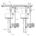
도 1은 본 발명인 도로 컷팅장치의 전체를 나타낸 측면 구성도이다.
도 2는 본 발명인 도로 컷팅장치의 구성요부 일측을 나타낸 사시도이다.
도 3은 본 발명인 도로 컷팅장치의 구성요부 타측을 나타낸 사시도이다.
도 4는 본 발명인 도로 컷팅장치의 구성요부인 지지체를 확대한 일부 생략 사시도이다.
도 5는 본 발명인 도로 컷팅장치의 컷팅체를 나타낸 분해사시도이다.
도 6 및 도 7은 본 발명인 도로 컷팅장치의 컷팅체 좌우 이동상태를 각각 나타낸 평면 구성도이다.
도 8은 본 발명인 도로 컷팅장치의 컷팅체 승하강 동작을 나타낸 측면 구성도이다.Figure 1 is a side view showing the entire configuration of the road cutting device of the present invention.
Figure 2 is a perspective view showing one side of a component of a road cutting device according to the present invention.
Figure 3 is a perspective view showing the other side of the components of the road cutting device of the present invention.
Figure 4 is an enlarged, partially omitted perspective view of a support, which is a component of the road cutting device of the present invention.
Figure 5 is an exploded perspective view showing a cutting body of the road cutting device of the present invention.
Figures 6 and 7 are plan views each showing the left and right movement state of the cutting body of the road cutting device of the present invention.
Figure 8 is a side view showing the raising and lowering operation of the cutting body of the road cutting device of the present invention.
이하, 상기 목적외에 본 발명의 다른 목적 및 특징들은 첨부 도면을 참조한 실시예에 대한 설명을 통하여 명백히 드러나게 될 것이다.Hereinafter, other purposes and features of the present invention in addition to the above will be clearly revealed through a description of embodiments with reference to the attached drawings.
다르게 정의되지 않는 한, 기술적이거나 과학적인 용어를 포함해서 여기서 사용되는 모든 용어들은 본 발명이 속하는 기술분야에서 통상의 지식을 가진 자에 의해 일반적으로 이해되는 것과 동일한 의미를 가지고 있다. 일반적으로 사용되는 사전에 정의되어 있는 것과 같은 용어들은 관련 기술의 문맥상 가지는 의미와 일치하는 의미를 가진 것으로 해석되어야 하며, 본 출원에서 명백하게 정의하지 않는 한, 이상적이거나 과도하게 형식적인 의미로 해석되지 않는다.Unless otherwise defined, all terms used herein, including technical or scientific terms, have the same meaning as commonly understood by one of ordinary skill in the art to which this invention belongs. Terms defined in commonly used dictionaries, such as those defined in common dictionaries, should be interpreted as having a meaning consistent with the meaning they have in the context of the relevant art, and will not be interpreted in an idealized or overly formal sense unless expressly defined in this application.
이하에서는, 본 발명의 실시예에 따른 도로 컷팅장치를 첨부된 도면을 참고하여 좀 더 구체적으로 설명한다.Hereinafter, a road cutting device according to an embodiment of the present invention will be described in more detail with reference to the attached drawings.
도시된 바와 같이 본 발명은, 엔진부(1)의 회전동력에 의해 무한궤도 회전하는 무한궤도 바퀴(2)를 갖는 본체(3)와, 상기 본체(3)의 전방측에 위치되되 본체(3)와 연결되는 지지체(100)와 상기 지지체(100)와 각각 연결되는 제1컷팅체(200) 및 제2컷팅체(300)를 포함하는 도로 컷팅장치에 관한 것으로, 상기 지지체(100)는, 상기 본체(3)의 전방에 위치되고 본체(3)와 일측이 용접고정되는 연결프레임(111)의 타측이 후면에 용접고정되고 전면 상단에 가로방향의 제1슬라이딩지지바(112)가 고정되며 전면 하단에 가로방향의 제2슬라이딩지지바(113)가 고정되는 지지프레임(110)과, 상기 제1슬라이딩지지바(112) 일측에 슬라이딩 연결되고 제1상단힌지부(121)를 갖는 제1상단슬라이딩가이드구(122) 및 제1슬라이딩지지바(112) 타측에 슬라이딩 연결되고 제2상단힌지부(123)를 갖는 제2상단슬라이딩가이드구(124)와, 상기 제2슬라이딩지지바(113) 일측에 슬라이딩 연결되고 제1하단힌지부(131)를 갖는 제1하단슬라이딩가이드구(132) 및 제2슬라이딩지지바(113) 타측에 슬라이딩 연결되고 제2하단힌지부(133)를 갖는 제2하단슬라이딩가이드구(134)와, 상기 제1하단힌지부(131)와 일측이 힌지연결되고 상단에 제1컷팅체힌지부(141)를 갖는 제1컷팅체지지프레임(140)과, 상기 제2하단힌지부(133)와 일측이 힌지연결되고 상단에 제2컷팅체힌지부(151)를 갖는 제2컷팅체지지프레임(150)과, 상기 제1상단힌지부(121)에 상측이 힌지연결되고 상기 제1컷팅체힌지부(141)에 하측이 힌지 연결되어 인출입 동작에 의해 상기 제1컷팅체지지프레임(140)을 상기 제1하단힌지부(131)를 축으로 들어올려주거나 내려주는 제1승하강실린더(160)와, 상기 제2상단힌지부(133)에 상측이 힌지연결되고 상기 제2컷팅체힌지부(151)에 하측이 힌지 연결되어 인출입 동작에 의해 상기 제2컷팅체지지프레임(150)을 상기 제2하단힌지부(133)를 축으로 들어올려주거나 내려주는 제2승하강실린더(170)로 구비된다.As described above, the present invention relates to a road cutting device including a main body (3) having an infinite track wheel (2) that infinitely rotates by the rotational power of an engine unit (1), a support body (100) positioned at the front side of the main body (3) and connected to the main body (3), and a first cutting body (200) and a second cutting body (300) each connected to the support body (100), wherein the support body (100) comprises a support frame (110) positioned at the front side of the main body (3) and having one side of a connecting frame (111) welded and fixed to the main body (3) and the other side of which is welded and fixed to the rear side, a first horizontal sliding support bar (112) is fixed to the upper front side, and a second horizontal sliding support bar (113) is fixed to the lower front side, and a first upper hinge part (121) that is slidably connected to one side of the first sliding support bar (112). A first upper sliding guide member (122) and a second upper sliding guide member (124) that is slidably connected to the other side of the first sliding support bar (112) and has a second upper hinge part (123), a first lower sliding guide member (132) that is slidably connected to one side of the second sliding support bar (113) and has a first lower hinge part (131), a second lower sliding guide member (134) that is slidably connected to the other side of the second sliding support bar (113) and has a second lower hinge part (133), a first cutting body support frame (140) that is hinge-connected to one side of the first lower hinge part (131) and has a first cutting body hinge part (141) at the upper end, and a second cutting body support frame (140) that is hinge-connected to the second lower hinge part (133) at the upper end. It is provided with a second cutting body support frame (150) having a second cutting body hinge part (151), a first raising/lowering cylinder (160) which is hinge-connected at the upper side to the first upper hinge part (121) and at the lower side to the first cutting body hinge part (141) to raise or lower the first cutting body support frame (140) with the first lower hinge part (131) as an axis by a drawing-in/out operation, and a second raising/lowering cylinder (170) which is hinge-connected at the upper side to the second upper hinge part (133) and at the lower side to the second cutting body hinge part (151) to raise or lower the second cutting body support frame (150) with the second lower hinge part (133) as an axis by a drawing-in/out operation.
상기 지지체(100)의 제1하단힌지부(131)는 제1하단슬라이딩가이드구(132)에 의해 상기 제2슬라이딩지지바(113)의 일측에 슬라이딩 연결되고, 상기 제2하단힌지부(133)는 제2하단슬라이딩가이드구(134)에 의해 상기 제2슬라이딩지지바(113)의 타측에 슬라이딩 연결됨에 따라, 상기 제1하단힌지부(131)와 일측이 힌지연결되는 제1컷팅체지지프레임(140)과 상기 제2하단힌지부(133)와 일측이 힌지연결되는 제2컷팅체지지프레임(150)이 상기 제2슬라이딩지지바(113)가 하단에 구비된 지지프레임(110)의 가로방향을 따라 좌우측 슬라이딩 이동될 때, 제1컷팅체지지프레임(140)과 제2컷팅체지지프레임(150)을 슬라이딩 가이드한다.The first lower hinge part (131) of the support (100) is slidably connected to one side of the second sliding support bar (113) by the first lower sliding guide part (132), and the second lower hinge part (133) is slidably connected to the other side of the second sliding support bar (113) by the second lower sliding guide part (134). Accordingly, when the first cutting body support frame (140) which has one side hinge-connected to the first lower hinge part (131) and the second cutting body support frame (150) which has one side hinge-connected to the second lower hinge part (133) slide left and right along the horizontal direction of the support frame (110) provided at the bottom of the second sliding support bar (113), the first cutting body support frame (140) and The second cutting body support frame (150) is guided by sliding.
이에 따라, 상기 제1컷팅체지지프레임(140)의 타측에 연결된 제1컷팅체(200) 및 상기 제2컷팅체지지프레임(150)의 타측에 연결된 제2컷팅체(300)가 지지프레임(110)에 대해 좌우측 방향으로 슬라이딩 이동이 용이하게 이루어진다.Accordingly, the first cutting body (200) connected to the other side of the first cutting body support frame (140) and the second cutting body (300) connected to the other side of the second cutting body support frame (150) can easily slide left and right with respect to the support frame (110).
상기 제1승하강실린더(160)는 상기 지지프레임(110)의 전면 상단에 가로방향으로 구비되는 제1슬라이딩지지바(112) 일측에 슬라이딩 연결되는 제1상단슬라이딩가이드구(122)와 상측이 힌지연결되고, 상기 제2승하강실린더(170)는 상기 제1슬라이딩지지바(112) 타측에 슬라이딩 연결되는 제2상단슬라이딩가이드구(124)와 상측이 힌지연결되어 있기 때문에, 상기 제1승하강실린더(160)와 제2승하강실린더(170)가 지지프레임(110)에 대해 좌우측 방향으로 슬라이딩 이동될 때, 상기 제1상단슬라이딩가이드구(122)와 제2상단슬라이딩가이드구(124)에 의해 상기 제1승하강실린더(160)와 제2승하강실린더(170)의 슬라이딩 이동이 가이드된다.The first raising/lowering cylinder (160) is hinge-connected at the upper side with the first upper sliding guide member (122) that is slidably connected to one side of the first sliding support bar (112) that is horizontally provided at the upper front side of the support frame (110), and the second raising/lowering cylinder (170) is hinge-connected at the upper side with the second upper sliding guide member (124) that is slidably connected to the other side of the first sliding support bar (112). Therefore, when the first raising/lowering cylinder (160) and the second raising/lowering cylinder (170) slide left and right with respect to the support frame (110), the sliding movement of the first raising/lowering cylinder (160) and the second raising/lowering cylinder (170) is performed by the first upper sliding guide member (122) and the second upper sliding guide member (124). It is guided.
본 발명은, 상기 지지프레임(110)에 대해 상기 제1컷팅체(200) 및 제2컷팅체(300)가 좌우측 이동이 가능하도록, 상기 제1하단힌지부(131)의 상단에는 제1좌우이동연결브라켓(181)이 구비되고, 상기 제2하단힌지부(133)의 상단에는 제2좌우이동연결브라켓(182)이 구비되며, 상기 지지프레임(110)에 일측이 연결되고 타측은 상기 제1좌우이동연결브라켓(181)에 연결되며 상기 지지프레임(110)에 대해 가로방향으로 위치되어, 인출입 동작에 의해 상기 지지프레임(100)에 대해 상기 제1하단힌지부(131)를 좌측 또는 우측방향으로 밀어주거나 당겨주는 제1좌우이동실린더(410)가 구비되며, 상기 지지프레임(110)에 일측이 연결되고 타측은 상기 제2좌우이동연결브라켓(182)에 연결되며 상기 지지프레임(110)에 대해 가로방향으로 위치되어, 인출인 동작에 의해 상기 지지프레임(110)에 대해 상기 제2하단힌지부(133)를 좌측 또는 우측방향으로 밀어주거나 당겨주는 제2좌우이동실린더(420)가 구비된다.The present invention provides a first left-right movement connecting bracket (181) provided on the upper end of the first lower hinge part (131) so that the first cutting body (200) and the second cutting body (300) can move left-right with respect to the support frame (110), and a second left-right movement connecting bracket (182) provided on the upper end of the second lower hinge part (133), and a first left-right movement cylinder (410) which is connected at one end to the support frame (110) and at the other end to the first left-right movement connecting bracket (181) and is positioned in a horizontal direction with respect to the support frame (110) and pushes or pulls the first lower hinge part (131) to the left or right with respect to the support frame (100) by a pull-out operation, and which is connected at one end to the support frame (110) and at the other end to the first left-right movement connecting bracket (181). A second left-right movement cylinder (420) is provided that is connected to the second left-right movement connecting bracket (182) and is positioned horizontally with respect to the support frame (110) and pushes or pulls the second lower hinge part (133) to the left or right with respect to the support frame (110) by a withdrawal motion.
이와 같이 이루어진 본 발명은, 상기 제1컷팅체(200)와 제2컷팅체(300)가 상기 지지프레임(110)에 대해 가로방향으로 좌우측 슬라이딩 이동됨이 용이하기 때문에, 제1컷팅체(200)와 제2컷팅체(3000의 간격 조절작업이 쉽게 이루어질 수 있다.The present invention, which is made in this manner, can easily adjust the gap between the first cutting body (200) and the second cutting body (300) because the first cutting body (200) and the second cutting body (300) can easily slide left and right with respect to the support frame (110).
즉, 본 발명의 상기 제1컷팅체(200)의 좌우 이동을 설명하면, 상기 지지프레임(110)에 일측이 고정된 제1좌우이동실린더(410)를 인출시키거나 인입시키면, 상기 제1좌우이동실린더(410)의 타측이 연결된 제1좌우이동연결브라켓(181)이 인출되거나 인입되는 제1좌우이동실린더(410)에 의해 밀리거나 당겨지게 되고, 이에 따라, 상기 제1좌우이동연결브라켓(181)이 상단에 구비된 제1하단힌지부(131)는 물론, 제1하단힌지부(131)와 일측이 힌지연결되는 상기 제1컷팅체지지프레임(140) 및 제1컷팅체지지프레임(140)의 타측과 연결되는 제1컷팅체(200)가 좌우측 방향으로 이동되면서 간격이 조절된다.That is, when explaining the left-right movement of the first cutting body (200) of the present invention, when the first left-right movement cylinder (410) of which one side is fixed to the support frame (110) is withdrawn or introduced, the first left-right movement connecting bracket (181) to which the other side of the first left-right movement cylinder (410) is connected is pushed or pulled by the first left-right movement cylinder (410) being withdrawn or introduced, and accordingly, the first lower hinge part (131) provided at the upper end of the first left-right movement connecting bracket (181), as well as the first cutting body support frame (140) of which one side is hinge-connected to the first lower hinge part (131) and the first cutting body (200) connected to the other side of the first cutting body support frame (140), move in the left-right direction, so that the gap is adjusted.
이 때, 상기 제1컷팅체지지프레임(140)에 구비된 제1컷팅체힌지부(141)와 하측이 힌지연결되는 제1승하강실린더(160) 역시 제1컷팅체지지프레임(140)과 동일하게 좌우측 방향으로 슬라이딩 이동된다.At this time, the first cutting body hinge part (141) provided on the first cutting body support frame (140) and the first raising/lowering cylinder (160) whose lower side is hinge-connected also slide in the left and right directions in the same way as the first cutting body support frame (140).
또한, 상기 제1좌우이동실린더(410)의 인출입 동작에 의해 상기 제1하단힌지부(131)와 제1컷팅체지지프레임(140), 제1승하강실린더(160) 및 상기 제1컷팅체지지프레임(140)의 타측과 연결된 제1컷팅체(200)가 지지프레임(110)에 대해 가로방향으로 좌우측 슬라이딩 이동될 때, 제1상단슬라이딩가이드구(122)와 제1하단슬라이딩가이드구(132)에 의해 슬라이딩 가이드된다.In addition, when the first lower hinge part (131), the first cutting body support frame (140), the first raising/lowering cylinder (160), and the first cutting body (200) connected to the other side of the first cutting body support frame (140) slide left and right in the horizontal direction with respect to the support frame (110) by the withdrawal/intake operation of the first left-right moving cylinder (410), the sliding is guided by the first upper sliding guide member (122) and the first lower sliding guide member (132).
이에 따라, 상기 제1컷팅체(200)를 지지프레임(110)의 가로방향에 대해 좌우측으로 슬라이딩 이동시킴이 용이하여 상기 제2컷팅체(300)에 대해 제1컷팅체(200)의 간격 조절작업을 편리하게 진행할 수 있다.Accordingly, it is easy to slide the first cutting body (200) left and right with respect to the horizontal direction of the support frame (110), so that the spacing adjustment work of the first cutting body (200) with respect to the second cutting body (300) can be conveniently performed.
또한, 본 발명의 상기 제2컷팅체(300)의 좌우 이동을 설명하면, 상기 지지프레임(110)에 일측이 고정된 제2좌우이동실린더(420)를 인출시키거나 인입시키면, 상기 제2좌우이동실린더(420)의 타측이 연결된 제2좌우이동연결브라켓(182)이 인출되거나 인입되는 제2좌우이동실린더(420)에 의해 밀리거나 당겨지게 되고, 이에 따라, 상기 제2좌우이동연결브라켓(182)이 상단에 구비된 제2하단힌지부(133)는 물론, 제2하단힌지부(133)와 일측이 힌지연결되는 상기 제2컷팅체지지프레임(150) 및 제2컷팅체지지프레임(150)의 타측과 연결되는 제2컷팅체(300)가 좌우측 방향으로 이동되면서 간격이 조절된다.In addition, when explaining the left-right movement of the second cutting body (300) of the present invention, when the second left-right movement cylinder (420) of which one side is fixed to the support frame (110) is withdrawn or introduced, the second left-right movement connecting bracket (182) to which the other side of the second left-right movement cylinder (420) is connected is pushed or pulled by the second left-right movement cylinder (420) being withdrawn or introduced, and accordingly, the second lower hinge part (133) provided at the upper end of the second left-right movement connecting bracket (182), as well as the second cutting body support frame (150) of which one side is hinge-connected to the second lower hinge part (133) and the second cutting body (300) connected to the other side of the second cutting body support frame (150), move in the left-right direction, so that the gap is adjusted.
이 때, 상기 제2컷팅체지지프레임(150)에 구비된 제2컷팅체힌지부(151)와 하측이 힌지연결되는 제2승하강실린더(170) 역시 제2컷팅체지지프레임(150)과 동일하게 좌우측 방향으로 슬라이딩 이동된다.At this time, the second cutting body hinge part (151) provided on the second cutting body support frame (150) and the second lifting and lowering cylinder (170) whose lower side is hinge-connected also slide in the left and right directions in the same way as the second cutting body support frame (150).
또한, 상기 제2좌우이동실린더(420)의 인출입 동작에 의해 상기 제2하단힌지부(133)와 제2컷팅체지지프레임(150), 제2승하강실린더(170) 및 상기 제2컷팅체지지프레임(150)의 타측과 연결된 제2컷팅체(300)가 지지프레임(110)에 대해 가로방향으로 좌우측 슬라이딩 이동될 때, 제2상단슬라이딩가이드구(124)와 제2하단슬라이딩가이드구(134)에 의해 슬라이딩 가이드된다.In addition, when the second cutting body (300) connected to the second lower hinge part (133), the second cutting body support frame (150), the second raising/lowering cylinder (170), and the other side of the second cutting body support frame (150) slides left and right in the horizontal direction with respect to the support frame (110) by the withdrawal/intake operation of the second left-right moving cylinder (420), the sliding is guided by the second upper sliding guide member (124) and the second lower sliding guide member (134).
이에 따라, 상기 제2컷팅체(300)를 지지프레임(110)의 가로방향에 대해 좌우측으로 슬라이딩 이동시킴이 용이하여 상기 제1컷팅체(200)에 대해 제2컷팅체(300)의 간격 조절작업을 편리하게 진행할 수 있다.Accordingly, it is easy to slide the second cutting body (300) left and right with respect to the horizontal direction of the support frame (110), so that the spacing adjustment work of the second cutting body (300) with respect to the first cutting body (200) can be conveniently performed.
더욱이, 본 발명은 상기 제1컷팅체(200)와 제2컷팅체(300)를 좌우측 방향으로 슬라이딩 이동시키는 제1좌우이동실린더(410)의 일측이 지지프레임(110)에 고정되고 타측은 상기 제1하단힌지부(131)에 구비된 제1좌우이동연결브라켓(181)에 연결되며, 상기 제2좌우이동실린더(420)의 일측이 지지프레임(110)에 고정되고 타측은 상기 제2하단힌지부(133)에 구비된 제2좌우이동연결브라켓(182)에 연결되어 있음에 따라, 상기 제1컷팅체(200) 및 제2컷팅체(300)와 직접 연결되지 않기 때문에, 제1컷팅체(200) 및 제2컷팅체(300)의 회전 진동 전달이 최소화될 수 있어 제1좌우이동실린더(410)와 제2좌우이동실린더(420)의 유동이나 흔들거림 및 틀어짐을 미연에 방지할 수 있다.Furthermore, the present invention is characterized in that one side of the first left-right movement cylinder (410) for sliding the first cutting body (200) and the second cutting body (300) in the left-right direction is fixed to the support frame (110) and the other side is connected to the first left-right movement connection bracket (181) provided in the first lower hinge part (131), and one side of the second left-right movement cylinder (420) is fixed to the support frame (110) and the other side is connected to the second left-right movement connection bracket (182) provided in the second lower hinge part (133), so that the first cutting body (200) and the second cutting body (300) are not directly connected, and therefore, the rotational vibration transmission of the first cutting body (200) and the second cutting body (300) can be minimized, and thus the first left-right movement cylinder (410) and It is possible to prevent movement, shaking, and distortion of the second left-right movement cylinder (420) in advance.
본 발명의 제1컷팅체(200)를 승하강시키는 동작은, 상기 제1승하강실린더(160)의 인출입 동작에 의해 이루어진다.The operation of raising and lowering the first cutting body (200) of the present invention is performed by the withdrawal/intake operation of the first raising/lowering cylinder (160).
즉, 상기 제1승하강실린더(160)의 승하강실린더봉을 인출시키면 상기 제1컷팅체지지프레임(140)에 구비된 제1컷팅체힌지부(141)가 밀어지면서 상기 제1컷팅체지지프레임(140)이 상기 제1하단힌지부(131)를 축으로 힌지 회전되면서 하강되고 이에 따라, 상기 제1컷팅체(200)가 하강된다.That is, when the raising/lowering cylinder rod of the first raising/lowering cylinder (160) is pulled out, the first cutting body hinge part (141) provided on the first cutting body support frame (140) is pushed, and the first cutting body support frame (140) is lowered while rotating the hinge about the first lower hinge part (131) as an axis, and accordingly, the first cutting body (200) is lowered.
또한, 상기 제1승하강실린더(160)의 승하강실린더봉을 인입시키면 상기 제1컷팅체지지프레임(140)에 구비된 제1컷팅체힌지부(141)가 당겨지면서, 상기 제1컷팅체지지프레임(140)이 상기 제1하단힌지부(131)를 축으로 힌지 회전되면서 승강되고 이에 따라, 상기 제1컷팅체(200)가 승강된다.In addition, when the raising/lowering cylinder rod of the first raising/lowering cylinder (160) is introduced, the first cutting body hinge part (141) provided on the first cutting body support frame (140) is pulled, and the first cutting body support frame (140) is raised/lowered while rotating the hinge about the first lower hinge part (131), thereby raising/lowering the first cutting body (200).
이와 같이 제1승하강실린더(160)에 의해 제1컷팅체(200)를 힌지 회전시켜 승강시킴에 따라, 도로면을 컷팅하지 않고 무한궤도 바퀴(2)에 의해 본체(3)를 전진 이동하거나 후진이동할 때 제1컷팅체(200)가 도로면에 닿아 간섭을 받는 것을 방지할 수 있다.In this way, by raising and lowering the first cutting body (200) by rotating the hinge by the first lifting and lowering cylinder (160), it is possible to prevent the first cutting body (200) from touching the road surface and causing interference when moving the main body (3) forward or backward by the caterpillar wheel (2) without cutting the road surface.
또한, 본 발명의 제2컷팅체(300)를 승하강시키는 동작은, 상기 제2승하강실린더(170)의 인출입 동작에 의해 이루어진다.In addition, the operation of raising and lowering the second cutting body (300) of the present invention is performed by the withdrawal/intake operation of the second raising/lowering cylinder (170).
즉, 상기 제2승하강실린더(170)의 승하강실린더봉을 인출시키면 상기 제2컷팅체지지프레임(150)에 구비된 제2컷팅체힌지부(151)가 밀어지면서 상기 제2컷팅체지지프레임(150)이 상기 제2하단힌지부(133)를 축으로 힌지 회전되면서 하강되고 이에 따라, 상기 제2컷팅체(300)가 하강된다.That is, when the raising/lowering cylinder rod of the second raising/lowering cylinder (170) is pulled out, the second cutting body hinge part (151) provided on the second cutting body support frame (150) is pushed, and the second cutting body support frame (150) is lowered while rotating the hinge about the second lower hinge part (133) as an axis, and accordingly, the second cutting body (300) is lowered.
또한, 상기 제2승하강실린더(170)의 승하강실린더봉을 인입시키면 상기 제2컷팅체지지프레임(150)에 구비된 제2컷팅체힌지부(151)가 당겨지면서, 상기 제2컷팅체지지프레임(150)이 상기 제2하단힌지부(133)를 축으로 힌지 회전되면서 승강되고 이에 따라, 상기 제2컷팅체(300)가 승강된다.In addition, when the raising/lowering cylinder rod of the second raising/lowering cylinder (170) is introduced, the second cutting body hinge part (151) provided on the second cutting body support frame (150) is pulled, and the second cutting body support frame (150) is raised/lowered while rotating the hinge about the second lower hinge part (133) as an axis, and accordingly, the second cutting body (300) is raised/lowered.
이와 같이 제2승하강실린더(170)에 의해 제2컷팅체(300)를 힌지 회전시켜 승강시킴에 따라, 도로면을 컷팅하지 않고 무한궤도 바퀴(2)에 의해 본체(3)를 전진 이동하거나 후진이동할 때 제2컷팅체(300)가 도로면에 닿아 간섭을 받는 것을 방지할 수 있다.In this way, by raising and lowering the second cutting body (300) by hinge rotation using the second lifting and lowering cylinder (170), it is possible to prevent the second cutting body (300) from touching the road surface and causing interference when moving the main body (3) forward or backward using the caterpillar wheel (2) without cutting the road surface.
본 발명의 상기 제1컷팅체(200)는, 상기 제1컷팅체지지프레임(140)의 전방측 끝단에 용접 고정되고 상단에 제1컷팅회전축지지부(211)가 구비되며 하단에 제1컷팅연동축지지부(212)를 갖는 제1컷팅구동지지대(210)와, 상기 제1컷팅회전축지지부(211)에 볼팅고정되고 상기 제1컷팅회전축지지부(211)에 관통 축설되는 제1컷팅회전축(221)이 구비되며 상기 제1컷팅회전축(221)에 축설되는 제1회전풀리(222)를 갖는 제1컷팅회전모터(220)와, 상기 제1컷팅구동지지대(210)의 하단에 구비된 제1컷팅연동축지지부(212)에 관통 축설되고 상기 제1회전풀리(222)와 제1회전벨트(231)로 연결되는 제1연동풀리(232)가 일측에 축설되는 제1컷팅연동축(230)과, 상기 제1컷팅연동축(230)의 타측에 축설되어 상기 제1컷팅연동축(230)의 회전동작에 의해 회전되고 제1컷팅날보호구(241)를 갖는 제1컷팅부(240)로 구비된다.The first cutting body (200) of the present invention comprises a first cutting drive support (210) that is welded and fixed to the front end of the first cutting body support frame (140) and has a first cutting rotational shaft support (211) at the upper end and a first cutting linkage shaft support (212) at the lower end, a first cutting rotational motor (220) that is bolted to the first cutting rotational shaft support (211) and has a first cutting rotational shaft (221) that penetrates and is installed in the first cutting rotational shaft support (211), and has a first rotational pulley (222) that is installed in the first cutting rotational shaft (221), and a first cutting drive support (210) that penetrates and is installed in the first cutting linkage shaft support (212) provided at the lower end of the first cutting drive support (210) and is connected to the first rotational pulley (222) by a first rotation belt (231). It is equipped with a first cutting linkage shaft (230) on one side of which a first linkage pulley (232) is mounted, and a first cutting part (240) mounted on the other side of the first cutting linkage shaft (230) and rotated by the rotational motion of the first cutting linkage shaft (230) and having a first cutting blade protector (241).
이와 같이 이루어진 본 발명의 제1컷팅체(200)는, 상기 제1컷팅회전모터(220)의 회전동력에 의해 상기 제1컷팅회전축(221)이 회전하면, 상기 제1컷팅회전축(221)에 축설된 제1회전풀리(222) 및 상기 제1회전풀리(222)와 제1회전벨트(231)로 연결된 제1연동풀리(232)가 회전되고, 이에 따라 제1연동풀리(232)가 축설된 상기 제1컷팅연동축(230)이 회전되며, 상기 제1컷팅연동축(230)의 타측에 축설된 제1컷팅부(240)가 회전하면서 도로면을 컷팅한다.The first cutting body (200) of the present invention formed in this manner rotates the first cutting rotation shaft (221) by the rotational power of the first cutting rotation motor (220), and the first rotation pulley (222) mounted on the first cutting rotation shaft (221) and the first linkage pulley (232) connected to the first rotation pulley (222) by the first rotation belt (231) rotate, and accordingly, the first cutting linkage shaft (230) mounted on the first linkage pulley (232) rotates, and the first cutting part (240) mounted on the other side of the first cutting linkage shaft (230) rotates to cut the road surface.
이 때, 상기 제1컷팅체(200)의 제1컷팅구동지지대(210) 상단에는, 상기 제1컷팅회전축(221)에 상단이 각각 끼움 축설되고, 하단이 상기 제1컷팅구동지지대(210) 상단에 용접 고정되는 제1회전축지지베어링(250)이 복수개 구비된다.At this time, a plurality of first rotation shaft support bearings (250) are provided on the upper part of the first cutting drive support (210) of the first cutting body (200), the upper part of which is respectively fitted to the first cutting rotation shaft (221) and the lower part of which is welded and fixed to the upper part of the first cutting drive support (210).
이에 따라, 상기 제1컷팅회전축(221)이 회전될 때, 제1컷팅회전축(221)의 흔들거림을 방지함은 물론, 상기 제1컷팅회전축(221)의 회전동작이 용이하게 이루어지도록 할 뿐만 아니라, 상기 제1컷팅부(240)의 회전진동이 상기 제1컷팅구동지지대(210) 및 제1컷팅구동지지대(210)에 타측이 연결된 상기 제1컷팅체지지프레임(140)에 전달되는 것을 최소화할 수 있다.Accordingly, when the first cutting rotation axis (221) rotates, it is possible to prevent the first cutting rotation axis (221) from shaking, and to facilitate the rotational motion of the first cutting rotation axis (221), as well as to minimize the transmission of the rotational vibration of the first cutting part (240) to the first cutting drive support (210) and the first cutting body support frame (140) whose other end is connected to the first cutting drive support (210).
또한, 상기 제1컷팅체지지프레임(140)에 구비되는 제1컷팅체힌지부(141)와 연결되는 제1승하강실린더(160)는 물론, 제1컷팅체지지프레임(140)과 힌지연결되는 제1하단힌지부(131)에 구비된 제1좌우이동연결브라켓(181)과 타측이 연결되는 제1좌우이동실린더(410)에 전달되는 회전진동을 최소화할 수 있다.In addition, the rotational vibration transmitted to the first raising/lowering cylinder (160) connected to the first cutting body hinge part (141) provided on the first cutting body support frame (140) as well as the first left/right moving connecting bracket (181) provided on the first lower hinge part (131) hinge-connected to the first cutting body support frame (140) and the first left/right moving cylinder (410) connected on the other side can be minimized.
본 발명의 상기 제2컷팅체(300)는, 상기 제2컷팅체지지프레임(150)의 전방측 끝단에 용접 고정되고 상단에 제2컷팅회전축지지부(311)가 구비되며 하단에 제2컷팅연동축지지부(312)를 갖는 제2컷팅구동지지대(310)와, 상기 제2컷팅회전축지지부(212)에 볼팅고정되고 상기 제2컷팅회전축지지부(212)에 관통 축설되는 제2컷팅회전축(321)이 구비되며 상기 제2컷팅회전축(321)에 축설되는 제2회전풀리(322)를 갖는 제2컷팅회전모터(320)와, 상기 제2컷팅구동지지대(310)의 하단에 구비된 제2컷팅연동축지지부(312)에 관통 축설되고 상기 제2회전풀리(322)와 제2회전벨트(331)로 연결되는 제2연동풀리(332)가 일측에 축설되는 제2컷팅연동축(330)과, 상기 제2컷팅연동축(330)의 타측에 축설되어 상기 제2컷팅연동축(330)의 회전동작에 의해 회전되고 제2컷팅날보호구(341)를 갖는 제2컷팅부(340)로 구비된다.The second cutting body (300) of the present invention comprises a second cutting drive support (310) which is welded and fixed to the front end of the second cutting body support frame (150) and has a second cutting rotational shaft support (311) at the upper end and a second cutting linkage shaft support (312) at the lower end, a second cutting rotational motor (320) which is bolted to the second cutting rotational shaft support (212) and has a second cutting rotational shaft (321) which penetrates and is installed in the second cutting rotational shaft support (212), and has a second rotational pulley (322) which is installed in the second cutting rotational shaft (321), and a second rotational belt (331) which penetrates and is installed in the second cutting linkage shaft support (312) provided at the lower end of the second cutting drive support (310) and is connected to the second rotational pulley (322). It is equipped with a second cutting linkage shaft (330) on one side of which a second linkage pulley (332) is mounted, and a second cutting part (340) mounted on the other side of the second cutting linkage shaft (330) and rotated by the rotational motion of the second cutting linkage shaft (330) and having a second cutting blade protector (341).
이와 같이 이루어진 본 발명의 제2컷팅체(300)는, 상기 제2컷팅회전모터(320)의 회전동력에 의해 상기 제2컷팅회전축(321)이 회전하면, 상기 제2컷팅회전축(321)에 축설된 제2회전풀리(322) 및 상기 제2회전풀리(322)와 제2회전벨트(331)로 연결된 제2연동풀리(332)가 회전되고, 이에 따라 제2연동풀리(332)가 축설된 상기 제2컷팅연동축(330)이 회전되며, 상기 제2컷팅연동축(330)의 타측에 축설된 제2컷팅부(340)가 회전하면서 도로면을 컷팅한다.The second cutting body (300) of the present invention formed in this manner rotates the second cutting rotation shaft (321) by the rotational power of the second cutting rotation motor (320), and the second rotation pulley (322) mounted on the second cutting rotation shaft (321) and the second linkage pulley (332) connected to the second rotation pulley (322) by the second rotation belt (331) rotate, and accordingly, the second cutting linkage shaft (330) mounted on the second linkage pulley (332) rotates, and the second cutting part (340) mounted on the other side of the second cutting linkage shaft (330) rotates to cut the road surface.
이 때, 상기 제2컷팅체(300)의 제2컷팅구동지지대(310) 상단에는, 상기 제2컷팅회전축(321)에 상단이 각각 끼움 축설되고, 하단이 상기 제2컷팅구동지지대(310) 상단에 용접 고정되는 제2회전축지지베어링(350)이 복수개 구비된다.At this time, a plurality of second rotation shaft support bearings (350) are provided on the upper part of the second cutting drive support (310) of the second cutting body (300), the upper part of which is respectively fitted to the second cutting rotation shaft (321) and the lower part of which is welded and fixed to the upper part of the second cutting drive support (310).
이에 따라, 상기 제2컷팅회전축(321)이 회전될 때, 제2컷팅회전축(321)의 흔들거림을 방지함은 물론, 상기 제2컷팅회전축(321)의 회전동작이 용이하게 이루어지도록 할 뿐만 아니라, 상기 제2컷팅부(340)의 회전진동이 상기 제2컷팅구동지지대(310) 및 제2컷팅구동지지대(310)에 타측이 연결된 상기 제2컷팅체지지프레임(150)에 전달되는 것을 최소화할 수 있다.Accordingly, when the second cutting rotation axis (321) rotates, it is possible to prevent the second cutting rotation axis (321) from shaking, and to facilitate the rotational motion of the second cutting rotation axis (321), as well as to minimize the transmission of the rotational vibration of the second cutting part (340) to the second cutting drive support (310) and the second cutting body support frame (150) whose other end is connected to the second cutting drive support (310).
또한, 상기 제2컷팅체지지프레임(150)에 구비되는 제2컷팅체힌지부(151)와 연결되는 제2승하강실린더(170)는 물론, 제2컷팅체지지프레임(150)과 힌지연결되는 제2하단힌지부(133)에 구비된 제2좌우이동연결브라켓(182)과 타측이 연결되는 제2좌우이동실린더(430)에 전달되는 회전진동을 최소화할 수 있다.In addition, the rotational vibration transmitted to the second raising/lowering cylinder (170) connected to the second cutting body hinge part (151) provided on the second cutting body support frame (150) as well as the second left-right moving cylinder (430) connected on the other side to the second left-right moving connecting bracket (182) provided on the second lower hinge part (133) hinge-connected to the second cutting body support frame (150) can be minimized.
본 발명의 상기 제1컷팅부(240)와 제2컷팅부(340)에는 각각, 상기 제1컷팅부(240)의 제1컷팅날보호구(241)와 제2컷팅부(340)의 제2컷팅날보호구(341)에 상단이 각각 용접되는 비산방지고정구(510)와, 상기 비산방지고정구(510)에 상단이 각각 연결되어 상기 제1컷팅부(240)와 제2컷팅부(340)에 의해 도로면이 컷팅될 때 발생되는 컷팅조각의 비산을 각각 방지하는 비산방지막(520)이 각각 구비된다.The first cutting section (240) and the second cutting section (340) of the present invention are each provided with a scatter prevention fixing member (510) whose upper ends are welded to the first cutting blade protection member (241) of the first cutting section (240) and the second cutting blade protection member (341) of the second cutting section (340), and a scatter prevention screen (520) whose upper ends are connected to the scatter prevention fixing member (510) to prevent scattering of cutting pieces generated when the road surface is cut by the first cutting section (240) and the second cutting section (340).
이와 같이 이루어진 본 발명은, 상기 제1컷팅체(200)의 제1컷팅부(240)와 제2컷팅체(300)의 제2컷팅부(340)에 의해 도로면이 컷팅됨에 따라 발생되는 컷팅조각들이 상기 비산방지막(520)에 의해 본체(3)측으로 날리는 것을 방지할 수 있음에 따라, 본체(3)측에 위치하고 있는 작업자는 물론, 본체(3)에 탑승한 작업자측으로 컷팅조각들이 날리게 되어 안전사고에 노출되는 것을 방지할 수 있다.The present invention, which is constructed in this manner, can prevent cutting pieces generated when the road surface is cut by the first cutting section (240) of the first cutting body (200) and the second cutting section (340) of the second cutting body (300) from flying toward the main body (3) by the scattering prevention film (520), thereby preventing workers located on the main body (3) side as well as workers riding on the main body (3) from being exposed to safety accidents due to cutting pieces flying toward them.
또한, 본 발명은 제1컷팅체(200)와 제2컷팅체(300)를 이용하여 도로면을 컷팅하거나 또는, 본체(3)를 이동시킬 때, 작업자가 본채(3)에 탑승한 상태에서 본체(3)에 구비된 무한궤도 바퀴(2)에 의해 쉽게 이동시킬 수 있어 작업자의 피로감을 최소화할 수 있다.In addition, when cutting a road surface or moving the main body (3) using the first cutting body (200) and the second cutting body (300), the worker can easily move the main body (3) by using the crawler wheels (2) provided on the main body (3) while riding on the main body (3), thereby minimizing worker fatigue.
이상과 같이 본 발명에서는 구체적인 구성 요소 등과 같은 특정 사항들과 한정된 실시예 및 도면에 의해 설명되었으나 이는 본 발명의 보다 전반적인 이해를 돕기 위해서 제공된 것일 뿐, 본 발명은 상기의 실시예에 한정되는 것은 아니며 본 발명이 속하는 기술분야에서 통상적인 지식을 가진 자라면 이러한 기재로부터 다양한 수정 및 변형이 가능하다.Although the present invention has been described with specific details such as specific components and limited examples and drawings, these have been provided only to help a more general understanding of the present invention, and the present invention is not limited to the above examples, and those with common knowledge in the technical field to which the present invention pertains can make various modifications and variations from this description.
따라서, 본 발명의 사상은 설명된 실시예에 국한되어 정해져서는 아니 되며, 후술하는 청구범위뿐 아니라 이 청구범위와 균등하거나 등가적 변형이 있는 모든 것들은 본 발명 사상의 범주에 속한다고 할 것이다.Therefore, the idea of the present invention should not be limited to the described embodiments, and all things that are equivalent or equivalent to the claims described below as well as the same shall fall within the scope of the idea of the present invention.
1 : 엔진부
2 : 무한궤도 바퀴
3 : 본체
100 : 지지체
110 : 지지프레임
111 : 연결프레임
112 : 제1슬라이딩지지바
113 : 제2슬라이딩지지바
121 : 제1상단힌지부
122 : 제1상단슬라이딩가이드구
123 : 제2상단힌지부
124 : 제2상단슬라이딩가이드구
131 : 제1하단힌지부
132 : 제1하단슬라이딩가이드구
133 : 제2하단힌지부
134 : 제2하단슬라이딩가이드구
140 : 제1컷팅체지지프레임
141 : 제1컷팅체힌지부
150 : 제2컷팅체지지프레임
151 : 제2컷팅체힌지부
160 : 제1승하강실린더
170 : 제2승하강실린더
181 : 제1좌우이동연결브라켓
182 : 제2좌우이동연결브라켓
200 : 제1컷팅체
210 : 제1컷팅체구동지지대
211 : 제1컷팅회전축지지부
212 : 제1컷팅연동축지지부
220 : 제2컷팅회전모터
221 : 제1컷팅회전축
222 : 제1회전풀리
230 : 제1컷팅연동축
231 : 제1회전벨트
232 : 제1연동풀리
240 : 제1컷팅부
241 : 제1컷팅날보호구
250 : 제1회전축지지베어링
300 : 제2컷팅체
310 : 제2컷팅구동지지대
311 : 제2컷팅회전축지지부
312 : 제2컷팅연동축지지부
320 : 제2컷팅회전모터
321 : 제2컷팅회전축
322 : 제2회전풀리
330 : 제2컷팅연동축
331 : 제2회전벨트
332 : 제2연동풀리
340 : 제2컷팅부
341 : 제2컷팅날보호구
350 : 제2회전축지지베어링
410 : 제1좌우이동실린더
420 : 제2좌우이동실린더
510 : 비산방지고정구
520 : 비산방지막1: Engine section 2: Track wheel
3: Body
100 : Support 110 : Support Frame
111: Connecting frame 112: First sliding support bar
113: Second sliding support bar 121: First upper hinge part
122: First upper sliding guide part 123: Second upper hinge part
124: Second upper sliding guide part 131: First lower hinge part
132: First lower sliding guide part 133: Second lower hinge part
134: Second lower sliding guide 140: First cutting body support frame
141: First cutting body hinge 150: Second cutting body support frame
151: 2nd cutting hinge 160: 1st lifting/lowering cylinder
170: 2nd lift cylinder 181: 1st left-right movement connecting bracket
182: 2nd left and right movement connecting bracket
200: 1st cutting body 210: 1st cutting body drive support
211: First cutting rotation axis support part 212: First cutting linkage axis support part
220: 2nd cutting rotation motor 221: 1st cutting rotation axis
222: 1st rotation pulley 230: 1st cutting linkage shaft
231: 1st rotation belt 232: 1st linkage pulley
240: 1st cutting section 241: 1st cutting blade protection device
250: First rotation axis support bearing
300: Second cutting body 310: Second cutting drive support
311: Second cutting rotation axis support part 312: Second cutting linkage axis support part
320: Second cutting rotation motor 321: Second cutting rotation axis
322: 2nd rotation pulley 330: 2nd cutting linkage shaft
331: Second rotation belt 332: Second linkage pulley
340: Second cutting section 341: Second cutting blade protection device
350: Second rotary shaft support bearing
410: 1st left-right movement cylinder 420: 2nd left-right movement cylinder
510: Anti-flying fixture 520: Anti-flying screen
Claims (4)
상기 지지체(100)는,
상기 본체(3)의 전방에 위치되고 본체(3)와 일측이 용접고정되는 연결프레임(111)의 타측이 후면에 용접고정되고 전면 상단에 가로방향의 제1슬라이딩지지바(112)가 고정되며 전면 하단에 가로방향의 제2슬라이딩지지바(113)가 고정되는 지지프레임(110)과;
상기 제1슬라이딩지지바(112) 일측에 슬라이딩 연결되고 제1상단힌지부(121)를 갖는 제1상단슬라이딩가이드구(122) 및 제1슬라이딩지지바(112) 타측에 슬라이딩 연결되고 제2상단힌지부(123)를 갖는 제2상단슬라이딩가이드구(124)와;
상기 제2슬라이딩지지바(113) 일측에 슬라이딩 연결되고 제1하단힌지부(131)를 갖는 제1하단슬라이딩가이드구(132) 및 제2슬라이딩지지바(113) 타측에 슬라이딩 연결되고 제2하단힌지부(133)를 갖는 제2하단슬라이딩가이드구(134)와;
상기 제1하단힌지부(131)와 일측이 힌지연결되고 상단에 제1컷팅체힌지부(141)를 갖는 제1컷팅체지지프레임(140)과;
상기 제2하단힌지부(133)와 일측이 힌지연결되고 상단에 제2컷팅체힌지부(151)를 갖는 제2컷팅체지지프레임(150)과;
상기 제1상단힌지부(121)에 상측이 힌지연결되고 상기 제1컷팅체힌지부(141)에 하측이 힌지 연결되어 인출입 동작에 의해 상기 제1컷팅체지지프레임(140)을 상기 제1하단힌지부(131)를 축으로 들어올려주거나 내려주는 제1승하강실린더(160)와;
상기 제2상단힌지부(133)에 상측이 힌지연결되고 상기 제2컷팅체힌지부(151)에 하측이 힌지 연결되어 인출입 동작에 의해 상기 제2컷팅체지지프레임(150)을 상기 제2하단힌지부(133)를 축으로 들어올려주거나 내려주는 제2승하강실린더(170)로 구비되고,
상기 제1컷팅체(200)는,
상기 제1컷팅체지지프레임(140)의 전방측 끝단에 용접 고정되고 상단에 제1컷팅회전축지지부(211)가 구비되며 하단에 제1컷팅연동축지지부(212)를 갖는 제1컷팅구동지지대(210)와;
상기 제1컷팅회전축지지부(211)에 볼팅고정되고 상기 제1컷팅회전축지지부(211)에 관통 축설되는 제1컷팅회전축(221)이 구비되며 상기 제1컷팅회전축(221)에 축설되는 제1회전풀리(222)를 갖는 제1컷팅회전모터(220)와;
상기 제1컷팅구동지지대(210)의 하단에 구비된 제1컷팅연동축지지부(212)에 관통 축설되고 상기 제1회전풀리(222)와 제1회전벨트(231)로 연결되는 제1연동풀리(232)가 일측에 축설되는 제1컷팅연동축(230)과;
상기 제1컷팅연동축(230)의 타측에 축설되어 상기 제1컷팅연동축(230)의 회전동작에 의해 회전되고 제1컷팅날보호구(241)를 갖는 제1컷팅부(240)로 구비되며,
상기 제2컷팅체(300)는,
상기 제2컷팅체지지프레임(150)의 전방측 끝단에 용접 고정되고 상단에 제2컷팅회전축지지부(311)가 구비되며 하단에 제2컷팅연동축지지부(312)를 갖는 제2컷팅구동지지대(310)와;
상기 제2컷팅회전축지지부(212)에 볼팅고정되고 상기 제2컷팅회전축지지부(212)에 관통 축설되는 제2컷팅회전축(321)이 구비되며 상기 제2컷팅회전축(321)에 축설되는 제2회전풀리(322)를 갖는 제2컷팅회전모터(320)와;
상기 제2컷팅구동지지대(310)의 하단에 구비된 제2컷팅연동축지지부(312)에 관통 축설되고 상기 제2회전풀리(322)와 제2회전벨트(331)로 연결되는 제2연동풀리(332)가 일측에 축설되는 제2컷팅연동축(330)과;
상기 제2컷팅연동축(330)의 타측에 축설되어 상기 제2컷팅연동축(330)의 회전동작에 의해 회전되고 제2컷팅날보호구(341)를 갖는 제2컷팅부(340)로 구비되는 것을 특징으로 하는 도로 컷팅장치.In a road cutting device including a main body (3) having an infinite track wheel (2) that infinitely rotates by the rotational power of an engine part (1), a support body (100) positioned at the front side of the main body (3) and connected to the main body (3), and a first cutting body (200) and a second cutting body (300) each connected to the support body (100),
The above support (100) is
A support frame (110) positioned in front of the main body (3) and having one side of the connection frame (111) welded and fixed to the main body (3) and the other side welded and fixed to the rear, a first horizontal sliding support bar (112) fixed to the upper front side, and a second horizontal sliding support bar (113) fixed to the lower front side;
A first upper sliding guide member (122) that is slidably connected to one side of the first sliding support bar (112) and has a first upper hinge part (121), and a second upper sliding guide member (124) that is slidably connected to the other side of the first sliding support bar (112) and has a second upper hinge part (123);
A first lower sliding guide member (132) that is slidably connected to one side of the second sliding support bar (113) and has a first lower hinge part (131), and a second lower sliding guide member (134) that is slidably connected to the other side of the second sliding support bar (113) and has a second lower hinge part (133);
A first cutting body support frame (140) having a first lower hinge part (131) and a first cutting body hinge part (141) at the upper end and hinge-connected on one side;
A second cutting body support frame (150) having a second lower hinge part (133) and a second cutting body hinge part (151) at the upper end and hinge-connected on one side;
A first lifting and lowering cylinder (160) that is hinge-connected at the upper side to the first upper hinge part (121) and hinge-connected at the lower side to the first cutting body hinge part (141) and raises or lowers the first cutting body support frame (140) with the first lower hinge part (131) as an axis by a pulling-out operation;
The second upper hinge part (133) is hinged at the upper side and the second cutting body hinge part (151) is hinged at the lower side, and the second cutting body support frame (150) is lifted or lowered by the second lower hinge part (133) as an axis by a pull-out operation, and is equipped with a second lifting and lowering cylinder (170).
The above first cutting body (200) is
A first cutting drive support (210) that is welded and fixed to the front end of the first cutting body support frame (140) and has a first cutting rotation shaft support (211) provided at the top and a first cutting linkage shaft support (212) at the bottom;
A first cutting rotation motor (220) having a first cutting rotation axis (221) that is bolted to the first cutting rotation axis support member (211) and penetrates the first cutting rotation axis support member (211) and has a first rotation pulley (222) that is installed on the first cutting rotation axis (221);
A first cutting linkage shaft (230) that is installed through the first cutting linkage shaft support member (212) provided at the bottom of the first cutting drive support member (210) and has a first linkage pulley (232) that is connected to the first rotation pulley (222) and the first rotation belt (231) installed on one side;
It is provided with a first cutting part (240) that is installed on the other side of the first cutting linkage shaft (230) and rotates by the rotational motion of the first cutting linkage shaft (230) and has a first cutting blade protection device (241).
The above second cutting body (300) is
A second cutting drive support (310) that is welded and fixed to the front end of the second cutting body support frame (150) and has a second cutting rotation shaft support (311) provided at the top and a second cutting linkage shaft support (312) at the bottom;
A second cutting rotation motor (320) having a second cutting rotation axis (321) that is bolted to the second cutting rotation axis support member (212) and penetrates the second cutting rotation axis support member (212) and has a second rotation pulley (322) that is installed on the second cutting rotation axis (321);
A second cutting linkage shaft (330) that is installed through the second cutting linkage shaft support member (312) provided at the bottom of the second cutting drive support member (310) and has a second linkage pulley (332) that is connected to the second rotation pulley (322) and the second rotation belt (331) installed on one side thereof;
A road cutting device characterized in that it is provided with a second cutting part (340) that is installed on the other side of the second cutting linkage shaft (330) and rotates by the rotational motion of the second cutting linkage shaft (330) and has a second cutting blade protector (341).
상기 지지프레임(110)에 대해 상기 제1컷팅체(200) 및 제2컷팅체(300)가 좌우측 이동이 가능하도록,
상기 제1하단힌지부(131)의 상단에는 제1좌우이동연결브라켓(181)이 구비되고,
상기 제2하단힌지부(133)의 상단에는 제2좌우이동연결브라켓(182)이 구비되며,
상기 지지프레임(110)에 일측이 연결되고 타측은 상기 제1좌우이동연결브라켓(181)에 연결되며 상기 지지프레임(110)에 대해 가로방향으로 위치되어, 인출입 동작에 의해 상기 지지프레임(100)에 대해 상기 제1하단힌지부(131)를 좌측 또는 우측방향으로 밀어주거나 당겨주는 제1좌우이동실린더(410)가 구비되며,
상기 지지프레임(110)에 일측이 연결되고 타측은 상기 제2좌우이동연결브라켓(182)에 연결되며 상기 지지프레임(110)에 대해 가로방향으로 위치되어, 인출인 동작에 의해 상기 지지프레임(110)에 대해 상기 제2하단힌지부(133)를 좌측 또는 우측방향으로 밀어주거나 당겨주는 제2좌우이동실린더(420)가 구비되는 것을 특징으로 하는 도로 컷팅장치.In the first paragraph,
The first cutting body (200) and the second cutting body (300) can move left and right with respect to the above support frame (110).
A first left-right movement connection bracket (181) is provided on the upper part of the first lower hinge part (131).
A second left-right movement connection bracket (182) is provided on the upper part of the second lower hinge part (133).
A first left-right moving cylinder (410) is provided, which is connected at one end to the support frame (110) and at the other end to the first left-right moving connecting bracket (181), and is positioned transversely to the support frame (110) to push or pull the first lower hinge part (131) to the left or right with respect to the support frame (100) by a pull-out/pull operation.
A road cutting device characterized in that it comprises a second left-right moving cylinder (420) which is connected at one end to the support frame (110) and at the other end to the second left-right moving connecting bracket (182), and is positioned transversely with respect to the support frame (110) so as to push or pull the second lower hinge part (133) to the left or right with respect to the support frame (110) by a withdrawal operation.
상기 제1컷팅체(200)의 제1컷팅구동지지대(210) 상단에는, 상기 제1컷팅회전축(221)에 상단이 각각 끼움 축설되고, 하단이 상기 제1컷팅구동지지대(210) 상단에 용접 고정되어 상기 제1컷팅회전축(221)이 회전될 때, 제1컷팅회전축(221)의 흔들거림을 방지하는 제1회전축지지베어링(250)이 복수개 구비되고,
상기 제2컷팅체(300)의 제2컷팅구동지지대(310) 상단에는, 상기 제2컷팅회전축(321)에 상단이 각각 끼움 축설되고, 하단이 상기 제2컷팅구동지지대(310) 상단에 용접 고정되어 상기 제2컷팅회전축(321)이 회전될 때, 제2컷팅회전축(321)의 흔들거림을 방지하는 제2회전축지지베어링(350)이 복수개 구비되는 것을 특징으로 하는 도로 컷팅장치.In the first paragraph,
At the upper end of the first cutting drive support (210) of the first cutting body (200), a plurality of first rotation shaft support bearings (250) are provided, each having an upper end fitted to the first cutting rotation shaft (221) and a lower end welded and fixed to the upper end of the first cutting drive support (210), to prevent the first cutting rotation shaft (221) from shaking when the first cutting rotation shaft (221) rotates.
A road cutting device characterized in that a plurality of second rotation shaft support bearings (350) are provided on the upper end of the second cutting drive support (310) of the second cutting body (300), the upper end of which is respectively fitted into the second cutting rotation shaft (321) and the lower end of which is welded and fixed to the upper end of the second cutting drive support (310), thereby preventing the second cutting rotation shaft (321) from shaking when the second cutting rotation shaft (321) rotates.
상기 제1컷팅부(240)와 제2컷팅부(340)에는 각각,
상기 제1컷팅부(240)의 제1컷팅날보호구(241)와 제2컷팅부(340)의 제2컷팅날보호구(341)에 상단이 각각 용접되는 비산방지고정구(510)와;
상기 비산방지고정구(510)에 상단이 각각 연결되어 상기 제1컷팅부(240)와 제2컷팅부(340)에 의해 도로면이 컷팅될 때 발생되는 컷팅조각의 비산을 각각 방지하는 비산방지막(520)이 각각 구비되는 것을 특징으로 하는 도로 컷팅장치.
In the first paragraph,
In the above first cutting part (240) and second cutting part (340), respectively,
A flying prevention fixing member (510) whose upper end is welded to the first cutting blade protection member (241) of the first cutting section (240) and the second cutting blade protection member (341) of the second cutting section (340);
A road cutting device characterized in that each of the upper ends of the above-mentioned anti-flying fixing member (510) is provided with an anti-flying screen (520) that prevents the cutting pieces from flying when the road surface is cut by the first cutting unit (240) and the second cutting unit (340).
Priority Applications (1)
| Application Number | Priority Date | Filing Date | Title |
|---|---|---|---|
| KR1020230049072A KR20240152984A (en) | 2023-04-14 | 2023-04-14 | road cutting machine |
Applications Claiming Priority (1)
| Application Number | Priority Date | Filing Date | Title |
|---|---|---|---|
| KR1020230049072A KR20240152984A (en) | 2023-04-14 | 2023-04-14 | road cutting machine |
Publications (1)
| Publication Number | Publication Date |
|---|---|
| KR20240152984A true KR20240152984A (en) | 2024-10-22 |
Family
ID=93289882
Family Applications (1)
| Application Number | Title | Priority Date | Filing Date |
|---|---|---|---|
| KR1020230049072A Ceased KR20240152984A (en) | 2023-04-14 | 2023-04-14 | road cutting machine |
Country Status (1)
| Country | Link |
|---|---|
| KR (1) | KR20240152984A (en) |
Citations (2)
| Publication number | Priority date | Publication date | Assignee | Title |
|---|---|---|---|---|
| KR100638858B1 (en) | 2004-11-05 | 2006-10-26 | 주식회사 시그마하이텍 | Cutters for Concrete Pavement |
| KR102133652B1 (en) | 2018-11-29 | 2020-07-13 | 주식회사 정도산업 | A road cutting machine |
-
2023
- 2023-04-14 KR KR1020230049072A patent/KR20240152984A/en not_active Ceased
Patent Citations (2)
| Publication number | Priority date | Publication date | Assignee | Title |
|---|---|---|---|---|
| KR100638858B1 (en) | 2004-11-05 | 2006-10-26 | 주식회사 시그마하이텍 | Cutters for Concrete Pavement |
| KR102133652B1 (en) | 2018-11-29 | 2020-07-13 | 주식회사 정도산업 | A road cutting machine |
Similar Documents
| Publication | Publication Date | Title |
|---|---|---|
| US20130082508A1 (en) | Side Plate Arrangement For A Milling Device, Use Of A Side Plate Arrangement And Milling Device With A Side Plate Arrangement | |
| KR101620407B1 (en) | Apparatus for circular cutting road surface to repair a manhole | |
| US3829161A (en) | Apparatus for milling road surfaces | |
| US11035097B2 (en) | Trench cutting machine | |
| US4516808A (en) | Pavement grinding apparatus | |
| US20190134851A1 (en) | Angled concrete saw and angled concrete saw kit along with a method of using the same | |
| CN109577652A (en) | Terrace robot | |
| NZ282742A (en) | Portable saw mill: end frame unison winding arrangement for saw carriage support rails | |
| CN113047142B (en) | Construction method for constructing asphalt concrete road | |
| KR20240152984A (en) | road cutting machine | |
| CN112252832B (en) | Construction protective guard suitable for complicated topography | |
| CA2424469C (en) | Masonry cutter | |
| DE10105475C1 (en) | Ditch digger, has digging wheels powered through a gearing, and can be hitched to a tractor with a protective upper shrouding and lower protective plate with height adjustment | |
| KR200452866Y1 (en) | Road Cutter with Automatic Tilting | |
| CA1247860A (en) | Subgrader machine | |
| KR100912647B1 (en) | Heavy-duty cutting device with adjustable angle | |
| KR102495999B1 (en) | Wire saw apparatus for excavator | |
| DE202020101184U1 (en) | Protection device for cutting disc | |
| CN215105414U (en) | Geotechnical engineering side slope reinforcing apparatus | |
| KR102117289B1 (en) | Road Cutting Device | |
| DE3815300C1 (en) | Method and apparatus for the retrospective lowering of kerbstones | |
| WO2018132049A1 (en) | Micro trench sawing device and method for sawing a micro trench | |
| JPH0670325B2 (en) | Slope construction equipment | |
| CN222293546U (en) | Telescopic lifting frame | |
| CN206090265U (en) | Joint cutter |
Legal Events
| Date | Code | Title | Description |
|---|---|---|---|
| PA0109 | Patent application |
St.27 status event code: A-0-1-A10-A12-nap-PA0109 |
|
| PA0201 | Request for examination |
St.27 status event code: A-1-2-D10-D11-exm-PA0201 |
|
| R18-X000 | Changes to party contact information recorded |
St.27 status event code: A-3-3-R10-R18-oth-X000 |
|
| R18-X000 | Changes to party contact information recorded |
St.27 status event code: A-3-3-R10-R18-oth-X000 |
|
| PG1501 | Laying open of application |
St.27 status event code: A-1-1-Q10-Q12-nap-PG1501 |
|
| D13-X000 | Search requested |
St.27 status event code: A-1-2-D10-D13-srh-X000 |
|
| D14-X000 | Search report completed |
St.27 status event code: A-1-2-D10-D14-srh-X000 |
|
| E902 | Notification of reason for refusal | ||
| PE0902 | Notice of grounds for rejection |
St.27 status event code: A-1-2-D10-D21-exm-PE0902 |
|
| E601 | Decision to refuse application | ||
| PE0601 | Decision on rejection of patent |
St.27 status event code: N-2-6-B10-B15-exm-PE0601 |
|
| E601 | Decision to refuse application | ||
| PE0601 | Decision on rejection of patent |
St.27 status event code: N-2-6-B10-B15-exm-PE0601 |
|
| R18 | Changes to party contact information recorded |
Free format text: ST27 STATUS EVENT CODE: A-3-3-R10-R18-OTH-X000 (AS PROVIDED BY THE NATIONAL OFFICE) |
|
| R18-X000 | Changes to party contact information recorded |
St.27 status event code: A-3-3-R10-R18-oth-X000 |