KR20240115687A - air conditioner AND controlling method OF AIR CONDITIONER - Google Patents
air conditioner AND controlling method OF AIR CONDITIONER Download PDFInfo
- Publication number
- KR20240115687A KR20240115687A KR1020230028603A KR20230028603A KR20240115687A KR 20240115687 A KR20240115687 A KR 20240115687A KR 1020230028603 A KR1020230028603 A KR 1020230028603A KR 20230028603 A KR20230028603 A KR 20230028603A KR 20240115687 A KR20240115687 A KR 20240115687A
- Authority
- KR
- South Korea
- Prior art keywords
- signal
- indoor
- air conditioner
- unit
- main controller
- Prior art date
- Legal status (The legal status is an assumption and is not a legal conclusion. Google has not performed a legal analysis and makes no representation as to the accuracy of the status listed.)
- Pending
Links
Images


Classifications
-
- F—MECHANICAL ENGINEERING; LIGHTING; HEATING; WEAPONS; BLASTING
- F24—HEATING; RANGES; VENTILATING
- F24F—AIR-CONDITIONING; AIR-HUMIDIFICATION; VENTILATION; USE OF AIR CURRENTS FOR SCREENING
- F24F11/00—Control or safety arrangements
- F24F11/62—Control or safety arrangements characterised by the type of control or by internal processing, e.g. using fuzzy logic, adaptive control or estimation of values
- F24F11/63—Electronic processing
- F24F11/65—Electronic processing for selecting an operating mode
-
- F—MECHANICAL ENGINEERING; LIGHTING; HEATING; WEAPONS; BLASTING
- F24—HEATING; RANGES; VENTILATING
- F24F—AIR-CONDITIONING; AIR-HUMIDIFICATION; VENTILATION; USE OF AIR CURRENTS FOR SCREENING
- F24F11/00—Control or safety arrangements
- F24F11/30—Control or safety arrangements for purposes related to the operation of the system, e.g. for safety or monitoring
- F24F11/41—Defrosting; Preventing freezing
-
- F—MECHANICAL ENGINEERING; LIGHTING; HEATING; WEAPONS; BLASTING
- F24—HEATING; RANGES; VENTILATING
- F24F—AIR-CONDITIONING; AIR-HUMIDIFICATION; VENTILATION; USE OF AIR CURRENTS FOR SCREENING
- F24F11/00—Control or safety arrangements
- F24F11/50—Control or safety arrangements characterised by user interfaces or communication
- F24F11/56—Remote control
-
- F—MECHANICAL ENGINEERING; LIGHTING; HEATING; WEAPONS; BLASTING
- F24—HEATING; RANGES; VENTILATING
- F24F—AIR-CONDITIONING; AIR-HUMIDIFICATION; VENTILATION; USE OF AIR CURRENTS FOR SCREENING
- F24F11/00—Control or safety arrangements
- F24F11/50—Control or safety arrangements characterised by user interfaces or communication
- F24F11/61—Control or safety arrangements characterised by user interfaces or communication using timers
-
- F—MECHANICAL ENGINEERING; LIGHTING; HEATING; WEAPONS; BLASTING
- F24—HEATING; RANGES; VENTILATING
- F24F—AIR-CONDITIONING; AIR-HUMIDIFICATION; VENTILATION; USE OF AIR CURRENTS FOR SCREENING
- F24F11/00—Control or safety arrangements
- F24F11/70—Control systems characterised by their outputs; Constructional details thereof
- F24F11/72—Control systems characterised by their outputs; Constructional details thereof for controlling the supply of treated air, e.g. its pressure
-
- H—ELECTRICITY
- H04—ELECTRIC COMMUNICATION TECHNIQUE
- H04L—TRANSMISSION OF DIGITAL INFORMATION, e.g. TELEGRAPHIC COMMUNICATION
- H04L12/00—Data switching networks
- H04L12/28—Data switching networks characterised by path configuration, e.g. LAN [Local Area Networks] or WAN [Wide Area Networks]
- H04L12/40—Bus networks
-
- F—MECHANICAL ENGINEERING; LIGHTING; HEATING; WEAPONS; BLASTING
- F24—HEATING; RANGES; VENTILATING
- F24F—AIR-CONDITIONING; AIR-HUMIDIFICATION; VENTILATION; USE OF AIR CURRENTS FOR SCREENING
- F24F2120/00—Control inputs relating to users or occupants
- F24F2120/20—Feedback from users
-
- F—MECHANICAL ENGINEERING; LIGHTING; HEATING; WEAPONS; BLASTING
- F24—HEATING; RANGES; VENTILATING
- F24F—AIR-CONDITIONING; AIR-HUMIDIFICATION; VENTILATION; USE OF AIR CURRENTS FOR SCREENING
- F24F2140/00—Control inputs relating to system states
- F24F2140/10—Pressure
- F24F2140/12—Heat-exchange fluid pressure
-
- H—ELECTRICITY
- H04—ELECTRIC COMMUNICATION TECHNIQUE
- H04L—TRANSMISSION OF DIGITAL INFORMATION, e.g. TELEGRAPHIC COMMUNICATION
- H04L12/00—Data switching networks
- H04L12/28—Data switching networks characterised by path configuration, e.g. LAN [Local Area Networks] or WAN [Wide Area Networks]
- H04L12/40—Bus networks
- H04L2012/40208—Bus networks characterized by the use of a particular bus standard
- H04L2012/40215—Controller Area Network CAN
Landscapes
- Engineering & Computer Science (AREA)
- Chemical & Material Sciences (AREA)
- Combustion & Propulsion (AREA)
- Mechanical Engineering (AREA)
- General Engineering & Computer Science (AREA)
- Signal Processing (AREA)
- Human Computer Interaction (AREA)
- Computer Networks & Wireless Communication (AREA)
- Physics & Mathematics (AREA)
- Fuzzy Systems (AREA)
- Mathematical Physics (AREA)
- Air Conditioning Control Device (AREA)
Abstract
Description
개시된 발명은 공기조화기 및 그 제어 방법에 관한 것이다.The disclosed invention relates to an air conditioner and a control method thereof.
공기조화기는 냉매의 증발 및 응축에서 생기는 열의 이동을 이용하여 공기를 냉각 또는 가열하고, 냉각 또는 가열된 공기를 토출시켜 실내 공간의 공기를 조화시키는 기기이다. 공기조화기는 냉방 운전 또는 난방 운전 시, 압축기와 실내 열교환기와 실외 열교환기를 통해 냉매를 순환시키고, 실내 열교환기에서 열교환된 공기를 실내 공간으로 토출함으로써 실내 공간을 냉각 또는 가열할 수 있다.An air conditioner is a device that cools or heats air using the movement of heat generated from the evaporation and condensation of a refrigerant, and discharges the cooled or heated air to condition the air in an indoor space. During cooling or heating operation, the air conditioner circulates refrigerant through a compressor, an indoor heat exchanger, and an outdoor heat exchanger, and discharges heat-exchanged air from the indoor heat exchanger into the indoor space, thereby cooling or heating the indoor space.
공기조화기는 접점 신호를 발생시키는 실내 제어기를 포함할 수 있고, 실내 제어기를 통해 입력되는 접점 신호에 따라 냉방과 난방을 제어할 수 있다. 그러나, 종래의 실내 제어기와 같은 외부 입력 장치는 에너지 효율이 개선된 실외기와 호환하는데 한계가 있다. The air conditioner may include an indoor controller that generates a contact signal, and can control cooling and heating according to the contact signal input through the indoor controller. However, external input devices such as conventional indoor controllers have limitations in being compatible with outdoor devices with improved energy efficiency.
더하여, 실외기와 실내기가 실내 제어기와 접점으로 연결되어 있으므로, 실내 팬의 별도 기능 제어가 불가능한 문제가 있었다.In addition, since the outdoor unit and the indoor unit are connected to the indoor controller through a contact point, there was a problem in that it was impossible to separately control the indoor fan function.
개시된 발명은 실내 제어기와 실내기의 교체 없이 실외기를 에너지 효율이 개선된 인버터 실외기로 교체할 수 있고, 실외기 및 실내기의 상태에 기초하여 실내 팬을 제어할 수 있는 공기조화기 및 공기조화기의 제어 방법을 제공한다.The disclosed invention is an air conditioner and a control method of an air conditioner that can replace an outdoor unit with an inverter outdoor unit with improved energy efficiency without replacing the indoor controller and indoor unit, and can control an indoor fan based on the status of the outdoor unit and indoor unit. provides.
본 문서에서 이루고자 하는 기술적 과제는 이상에서 언급한 기술적 과제로 제한되지 않으며, 언급되지 않은 또 다른 기술적 과제들은 아래의 기재로부터 본 발명이 속하는 기술분야에서 통상의 지식을 가진 자에게 명확하게 이해될 수 있을 것이다. The technical problem to be achieved in this document is not limited to the technical problem mentioned above, and other technical problems not mentioned can be clearly understood by those skilled in the art from the description below. There will be.
일 실시예에 따른 공기조화기는 사용자로부터 운전 명령을 입력 받고, 상기 운전 명령에 대응되는 복수의 제1 신호를 발생시키는 실내 제어기, 상기 실내 제어기와 연결되어 상기 복수의 제1 신호를 수신하고, 상기 복수의 제1 신호를 조합하여 하나의 제2 신호로 변환하는 메인 제어기, 상기 메인 제어기와 연결되어 상기 메인 제어기로부터 수신된 상기 하나의 제2 신호에 기초하여 동작하고, 실외기 운전 상태에 대응되는 제3 신호를 발생시키는 실외기 및 상기 메인 제어기와 연결되어 실내 팬이 마련되는 실내기를 포함하고, 상기 메인 제어기는, 상기 복수의 제1 신호와 상기 제3 신호에 기초하여 상기 실내 팬을 제어한다.An air conditioner according to an embodiment includes an indoor controller that receives an operation command from a user, generates a plurality of first signals corresponding to the operation command, and is connected to the indoor controller to receive the plurality of first signals, A main controller that combines a plurality of first signals and converts them into one second signal, is connected to the main controller and operates based on the one second signal received from the main controller, and a second signal corresponding to the outdoor unit operating state. An outdoor unit that generates three signals and an indoor unit connected to the main controller and provided with an indoor fan, wherein the main controller controls the indoor fan based on the plurality of first signals and the third signal.
일 실시예에 따른 공기조화기 제어 방법은, 실내 제어기가 사용자로부터 운전 명령을 입력 받아 상기 운전 명령에 대응되는 복수의 제1 신호를 발생시키고, 메인 제어기가 상기 실내 제어기와 연결되어 상기 복수의 제1 신호를 수신하고, 상기 복수의 제1 신호를 조합하여 하나의 제2 신호로 변환하고, 실외기가 상기 메인 제어기와 연결되어 상기 메인 제어기로부터 수신된 상기 하나의 제2 신호에 기초하여 동작하고, 실외기 운전 상태에 대응되는 제3 신호를 발생시키고. 상기 복수의 제1 신호와 상기 제3 신호에 기초하여 상기 실내기팬을 제어하는 것을 포함한다.In an air conditioner control method according to an embodiment, an indoor controller receives an operation command from a user and generates a plurality of first signals corresponding to the operation command, and a main controller is connected to the indoor controller to generate the plurality of first signals. Receives a first signal, combines the plurality of first signals and converts them into one second signal, and the outdoor unit is connected to the main controller and operates based on the one second signal received from the main controller, Generating a third signal corresponding to the outdoor unit operating state. and controlling the indoor unit fan based on the plurality of first signals and the third signal.
도 1은 일 실시예에 따른 공기조화기의 구성을 도시한다.
도 2는 일 실시예에 따른 공기조화기의 제어 구성을 도시한다.
도 3은 일 실시예에 따른 메인 제어기를 도시한다.
도 4는 일 실시예에 따른 공기조화기에서 메인 제어기와 공기조화기의의 회구성 간 연결을 도시한다.
도 5는 일 실시예에 따른 메인 제어기에 의해 제상 운전이 제어되는 과정을 도시한다.
도 6은 일 실시예에 따른 메인 제어기에 의해 냉풍 방지 기능이 제어되는 과정을 도시한다.
도 7은 일 실시예에 따른 메인 제어기에 의해 풍량이 약풍으로 제어되는 과정을 도시한다.
도 8은 일 실시예에 따른 공기조화기에서 실외기로부터 약풍 신호가 출력되는 것을 도시한다.
도 9는 일 실시예에 따른 메인 제어기에 의해 풍량이 미풍으로 제어되는 과정을 도시한다.
도 10은 일 실시예에 따른 공기조화기에서 실외기로부터 미풍 신호가 출력되는 것을 도시한다.
도 11은 일 실시예에 따른 공기조화기에서 제2 신호가 제상 운전 진입 신호를 포함하는 경우의 제어 흐름도를 도시한다.
도 12는 일 실시예에 따른 공기조화기에서 제2 신호가 냉풍 방지 신호를 포함하는 경우의 제어 흐름도를 도시한다.
도 13은 일 실시예에 따른 공기조화기에서 제2 신호가 풍량 조절 신호를 포함하는 경우의 제어 흐름도를 도시한다.Figure 1 shows the configuration of an air conditioner according to an embodiment.
Figure 2 shows the control configuration of an air conditioner according to one embodiment.
Figure 3 shows a main controller according to one embodiment.
Figure 4 shows the connection between the main controller and the air conditioner in the air conditioner according to one embodiment.
Figure 5 shows a process in which the defrost operation is controlled by the main controller according to one embodiment.
Figure 6 shows a process in which the cold wind prevention function is controlled by the main controller according to one embodiment.
Figure 7 shows a process in which the wind speed is controlled to a weak wind by the main controller according to one embodiment.
Figure 8 shows a weak wind signal being output from an outdoor unit in an air conditioner according to an embodiment.
Figure 9 shows a process in which wind volume is controlled to be a gentle breeze by the main controller according to one embodiment.
FIG. 10 shows a breeze signal being output from an outdoor unit in an air conditioner according to an embodiment.
Figure 11 shows a control flowchart when the second signal includes a defrost operation start signal in an air conditioner according to an embodiment.
FIG. 12 shows a control flowchart when the second signal includes a cold wind prevention signal in an air conditioner according to an embodiment.
Figure 13 shows a control flowchart when the second signal includes an air volume control signal in an air conditioner according to an embodiment.
본 문서의 다양한 실시예들 및 이에 사용된 용어들은 본 문서에 기재된 기술적 특징들을 특정한 실시예들로 한정하려는 것이 아니며, 해당 실시예의 다양한 변경, 균등물, 또는 대체물을 포함하는 것으로 이해되어야 한다.The various embodiments of this document and the terms used herein are not intended to limit the technical features described in this document to specific embodiments, but should be understood to include various changes, equivalents, or replacements of the embodiments.
도면의 설명과 관련하여, 유사한 또는 관련된 구성요소에 대해서는 유사한 참조 부호가 사용될 수 있다.In connection with the description of the drawings, similar reference numbers may be used for similar or related components.
아이템에 대응하는 명사의 단수 형은 관련된 문맥상 명백하게 다르게 지시하지 않는 한, 상기 아이템 한 개 또는 복수 개를 포함할 수 있다.The singular form of a noun corresponding to an item may include one or more of the items, unless the relevant context clearly indicates otherwise.
본 문서에서, "A 또는 B", "A 및 B 중 적어도 하나", "A 또는 B 중 적어도 하나", "A, B 또는 C", "A, B 및 C 중 적어도 하나", 및 "A, B, 또는 C 중 적어도 하나"와 같은 문구들 각각은 그 문구들 중 해당하는 문구에 함께 나열된 항목들 중 어느 하나, 또는 그들의 모든 가능한 조합을 포함할 수 있다.As used herein, “A or B”, “at least one of A and B”, “at least one of A or B”, “A, B or C”, “at least one of A, B and C”, and “A Each of phrases such as “at least one of , B, or C” may include any one of the items listed together in the corresponding phrase, or any possible combination thereof.
"및/또는"이라는 용어는 복수의 관련된 기재된 구성요소들의 조합 또는 복수의 관련된 기재된 구성요소들 중의 어느 구성요소를 포함한다.The term “and/or” includes any element of a plurality of related described elements or a combination of a plurality of related described elements.
"제1", "제2", 또는 "첫째" 또는 "둘째"와 같은 용어들은 단순히 해당 구성요소를 다른 해당 구성요소와 구분하기 위해 사용될 수 있으며, 해당 구성요소들을 다른 측면(예: 중요성 또는 순서)에서 한정하지 않는다.Terms such as "first", "second", or "first" or "second" may be used simply to distinguish one element from another, and may be used to distinguish such elements in other respects, such as importance or order) is not limited.
어떤(예: 제1) 구성요소가 다른(예: 제2) 구성요소에, "기능적으로" 또는 "통신적으로"라는 용어와 함께 또는 이런 용어 없이, "커플드" 또는 "커넥티드"라고 언급된 경우, 그것은 상기 어떤 구성요소가 상기 다른 구성요소에 직접적으로(예: 유선으로), 무선으로, 또는 제3 구성요소를 통하여 연결될 수 있다는 것을 의미한다.One (e.g. first) component is said to be "coupled" or "connected" to another (e.g. second) component, with or without the terms "functionally" or "communicatively". Where mentioned, it means that any of the components can be connected to the other components directly (e.g. wired), wirelessly, or through a third component.
"포함하다" 또는 "가지다"등의 용어는 본 문서에 기재된 특징, 숫자, 단계, 동작, 구성요소, 부품 또는 이들을 조합한 것이 존재함을 지정하려는 것이지, 하나 또는 그 이상의 다른 특징들이나 숫자, 단계, 동작, 구성요소, 부품 또는 이들을 조합한 것들의 존재 또는 부가 가능성을 미리 배제하지 않는다.Terms such as “include” or “have” are intended to designate the existence of features, numbers, steps, operations, components, parts, or combinations thereof described in this document, but are not intended to include one or more other features, numbers, or steps. , does not exclude in advance the possibility of the existence or addition of operations, components, parts, or combinations thereof.
어떤 구성요소가 다른 구성요소와 "연결", "결합", "지지" 또는 "접촉"되어 있다고 할 때, 이는 구성요소들이 직접적으로 연결, 결합, 지지 또는 접촉되는 경우뿐 아니라, 제3 구성요소를 통하여 간접적으로 연결, 결합, 지지 또는 접촉되는 경우를 포함한다.When a component is said to be “connected,” “coupled,” “supported,” or “in contact” with another component, this means not only when the components are directly connected, coupled, supported, or in contact with a third component. This includes cases where it is indirectly connected, coupled, supported, or contacted through.
어떤 구성요소가 다른 구성요소 "상에" 위치하고 있다고 할 때, 이는 어떤 구성요소가 다른 구성요소에 접해 있는 경우뿐 아니라 두 구성요소 사이에 또 다른 구성요소가 존재하는 경우도 포함한다. When a component is said to be located “on” another component, this includes not only cases where a component is in contact with another component, but also cases where another component exists between the two components.
다양한 실시예들에 따른 공기조화기(1)는, 공기 조화 공간(이하에서는 "실내"라 한다)에서 공기정화, 환기, 습도 조절, 냉방 또는 난방 등의 기능을 수행하는 장치로서, 이러한 기능들 중 적어도 하나를 구비한 장치를 의미한다. The
일 실시예에 따르면, 공기조화기(1)는 냉방 기능 또는 난방 기능을 수행하기 위해 히트펌프 장치를 포함할 수 있다. 히트펌프 장치는 압축기, 제1열교환기, 팽창 장치 및 제2열교환기를 따라 냉매가 순환되는 냉동사이클을 포함할 수 있다. 공기조화기(1)의 외관을 형성하는 하나의 하우징에 히트펌프 장치의 모든 구성품이 내장될 수 있는데, 창문형 에어컨 또는 이동형 에어컨이 이러한 공기조화기(1)에 해당한다. 다른 한편으로는 하나의 공기조화기(1)를 형성하는 복수의 하우징에 히트펌프 장치의 일부 구성품이 나뉘어 내장될 수도 있는데, 벽걸이형 에어컨, 스텐드형 에어컨, 시스템 에어컨 등이 여기에 포함된다.According to one embodiment, the
복수의 하우징을 포함하는 공기조화기(1)는 실외에 설치되는 적어도 하나의 실외기(20)와 실내에 설치되는 적어도 하나의 실내기(30)를 포함할 수 있다. 일 예로 공기조화기(1)는 1개의 실외기(20)와 1개의 실내기(30)가 냉매관을 통해 연결되도록 마련될 수 있다. 일 예로 공기조화기(1)는 1개의 실외기(20)가 냉매관을 통해 2개 이상의 실내기(30)와 연결되도록 마련될 수 있다. 일 예로 공기조화기(1)는 2개 이상의 실외기(20)와 2개 이상의 실내기(30)가 복수의 냉매관으로 연결되도록 마련될 수 있다.The
실외기(20)는 실내기(30)와 전기적으로 연결될 수 있다. 예를 들어, 실외기(20) 또는 실내기(30)에 마련된 입력 인터페이스를 통해 공기조화기(1)를 제어하기 위한 정보(또는 명령)를 입력할 수 있으며, 사용자 입력에 응답하여 실외기(20) 및 실내기(30)가 동시에 또는 순차적으로 동작할 수 있다.The
공기조화기(1)는 실외기(20)에 마련되는 실외 열교환기, 실내기(30)에 마련되는 실내 열교환기, 실외 열교환기와 실내 열교환기를 연결하는 냉매관을 포함할 수 있다.The
실외 열교환기는 냉매의 상 변화(예를 들어, 증발 또는 응축)를 이용하여 냉매와 실외 공기 사이의 열 교환을 수행할 수 있다. 예를 들어, 실외 열교환기에서 냉매가 응축되는 동안 냉매는 실외 공기로 열을 방출하고, 실외 열교환기에 흐르는 냉매가 증발하는 동안 냉매는 실외 공기에서 열을 흡수할 수 있다.An outdoor heat exchanger can perform heat exchange between a refrigerant and outdoor air using a phase change (eg, evaporation or condensation) of the refrigerant. For example, while the refrigerant is condensed in an outdoor heat exchanger, the refrigerant may release heat to the outdoor air, and while the refrigerant flowing in the outdoor heat exchanger evaporates, the refrigerant may absorb heat from the outdoor air.
실내기(30)는 실내에 마련된다. 일 예로 실내기(30)는 배치되는 방법에 따라 천정형 실내기(30), 스탠드형 실내기(30), 벽걸이형 실내기(30) 등으로 구분될 수 있다. 일 예로 천정형 실내기(30)는 공기가 토출되는 방식에 따라 4-way형 실내기(30), 1-way 형 실내기(30), 덕트형 실내기(30) 등으로 구분될 수 있다.The
마찬가지로 실내 열교환기는 냉매의 상 변화(예를 들어, 증발 또는 응축)를 이용하여 냉매와 실내 공기 사이의 열 교환을 수행할 수 있다. 예를 들어, 실내기(30)에서 냉매가 증발하는 동안 냉매는 실내 공기에서 열을 흡수할 수 있으며, 냉각된 실내 열교환기를 거치면서 냉각된 실내 공기를 송풍함으로써 실내가 냉방될 수 있다. 또한, 실내 열교환기에서 냉매가 응축되는 동안 냉매는 실내 공기로 열을 방출할 수 있으며, 고온의 실내 열교환기를 거치면서 가열된 실내 공기를 송풍함으로써 실내가 난방될 수 있다. Likewise, an indoor heat exchanger may utilize a phase change (e.g., evaporation or condensation) of the refrigerant to perform heat exchange between the refrigerant and indoor air. For example, while the refrigerant evaporates in the
즉, 공기조화기(1)는 실외 열교환기와 실내 열교환기를 순환하는 냉매의 상 변화 과정을 통해 냉방 또는 난방 기능을 수행하게 되는데, 이러한 냉매의 순환을 위해 공기조화기(1)는 냉매를 압축하는 압축기를 포함할 수 있다. 압축기는 흡입부를 통해 냉매 가스를 흡입하고, 냉매 가스를 압축할 수 있다. 압축기는 배출부를 통해 고온 고압의 냉매 가스를 배출할 수 있다. 압축기는 실외기(20) 내부에 배치될 수 있다.In other words, the air conditioner (1) performs a cooling or heating function through the phase change process of the refrigerant circulating between the outdoor heat exchanger and the indoor heat exchanger. For this circulation of the refrigerant, the air conditioner (1) compresses the refrigerant. May include a compressor. The compressor can suck in refrigerant gas through a suction part and compress the refrigerant gas. The compressor can discharge high-temperature, high-pressure refrigerant gas through the discharge unit. The compressor may be placed inside the
냉매는 냉매관을 통해 압축기, 실외 열교환기, 팽창 장치 및 실내 열교환기의 순서로 순환하거나, 또는 압축기, 실내 열교환기, 팽창 장치 및 실외 열교환기의 순서로 순환할 수 있다. The refrigerant may circulate through the refrigerant pipe in the following order: compressor, outdoor heat exchanger, expansion device, and indoor heat exchanger, or may circulate in the following order: compressor, indoor heat exchanger, expansion device, and outdoor heat exchanger.
일 예로 공기조화기(1)는 1개의 실외기(20)와 1개의 실내기(30)가 냉매관을 통해 직접 연결될 경우, 냉매는 냉매관을 통해 1개의 실외기(20)와 1개의 실내기(30) 사이에서 순환되도록 마련될 수 있다.For example, when the air conditioner (1) has one outdoor unit (20) and one indoor unit (30) directly connected through a refrigerant pipe, the refrigerant is connected to one outdoor unit (20) and one indoor unit (30) through the refrigerant pipe. It can be arranged to circulate between them.
일 예로 공기조화기(1)는 1개의 실외기(20)가 냉매관을 통해 2개 이상의 실내기(30)와 연결될 경우, 냉매는 실외기(20)에서부터 분기되는 냉매관을 통해 복수의 실내기(30)로 흐를 수 있다. 복수의 실내기(30)에서 토출된 냉매는 합류되어 실외기(20)로 순환되도록 마련될 수 있다. 일 예로 복수의 실내기(30)는 각각 별도의 냉매관을 통해 직접 1개의 실외기(20)와 병렬적으로 연결될 수 있다.For example, in the air conditioner (1), when one outdoor unit (20) is connected to two or more indoor units (30) through a refrigerant pipe, the refrigerant is supplied to a plurality of indoor units (30) through the refrigerant pipe branching from the outdoor unit (20). can flow. The refrigerants discharged from the plurality of
복수의 실내기(30)는 각각 사용자가 설정한 작동 모드에 따라 독립적으로 작동될 수 있다. 즉, 복수의 실내기(30) 중 일부는 냉방 모드로 작동되고 동시에 다른 일부는 난방 모드로 작동될 수. 이 때, 냉매는 후술할 유로 전환 밸브를 통해 지정된 순환 경로를 따라 선택적으로 고압 또는 저압의 상태로 각각의 실내기(30)로 유입되고, 토출되어 실외기(20)로 순환되도록 마련될 수 있다.Each of the plurality of
일 예로 공기조화기(1)는 2개 이상의 실외기(20)와 2개 이상의 실내기(30)가 복수의 냉매관을 통해 연결될 시, 복수의 실외기(20)에서 토출된 냉매가 합류되어 하나의 냉매관을 통해 흐르다가 어느 지점에서 다시 분기되어 복수의 실내기(30)로 유입될 수 있다. For example, in the air conditioner (1), when two or more outdoor units (20) and two or more indoor units (30) are connected through a plurality of refrigerant pipes, the refrigerant discharged from the plurality of outdoor units (20) are combined to form one refrigerant. While flowing through the pipe, it may branch again at some point and flow into a plurality of indoor units (30).
복수의 실외기(20)는 복수의 실내기(30)의 운전량에 따른 운전 부하에 따라 모두 구동되거나 적어도 일부는 구동되지 않을 수 있다. 이 때 냉매는 유로 전환 밸브를 통해 선택적으로 구동되는 실외기(20)로 유입되어 순환되도록 마련될 수 있다. 공기조화기(1)는 열교환기로 유입되는 냉매의 압력을 낮추기 위해 팽창 장치를 포함할 수 있다. 일 예로 팽창 장치는 실내기(30) 내부 또는 실외기(20) 내부에 배치될 수 있으며, 양쪽 모두에 배치될 수도 있다.All of the plurality of
팽창 장치는 일 예로 교축 효과를 이용하여 냉매의 온도 및 압력을 낮출 수 있다. 팽창 장치는 유로의 단면적을 감소시킬 수 있는 오리피스(orifice)를 포함할 수 있다. 오리피스를 통과한 냉매는 온도 및 압력이 낮아질 수 있다.For example, the expansion device can lower the temperature and pressure of the refrigerant using a throttling effect. The expansion device may include an orifice that may reduce the cross-sectional area of the flow path. The temperature and pressure of the refrigerant that passes through the orifice may be lowered.
팽창 장치는 일 예로 개방 비율(완전 개방된 상태에서 밸브의 유로의 단면적에 대한 부분 개방된 상태에서 밸브의 유로의 단면적의 비율)를 조절할 수 있는 전자 팽창 밸브로 구현될 수 있다. 전자 팽창 밸브의 개방 비율에 의존하여 팽창 장치를 통과하는 냉매의 양이 제어될 수 있다.For example, the expansion device may be implemented as an electronic expansion valve that can adjust the opening ratio (ratio of the cross-sectional area of the valve's flow path in a partially opened state to the cross-sectional area of the valve's flow path in a fully opened state). Depending on the opening rate of the electronic expansion valve, the amount of refrigerant passing through the expansion device can be controlled.
공기조화기(1)는 냉매 순환 유로상에 배치되는 유로 전환 밸브를 더 포함할 수 있다. 유로 전환 밸브는 예를 들어 4방 밸브(4-way valve)를 포함할 수 있다. 유로 전환 밸브는 실내기(30)의 운전 모드(예를 들어, 냉방 운전 또는 난방 운전)에 의존하여 냉매의 순환 경로를 결정할 수 있다. 유로 전환 밸브는 압축기의 배출부에 연결될 수 있다.The
공기조화기(1)는 어큐뮬레이터를 포함할 수 있다. 어큐뮬레이터는 압축기의 흡입부에 연결될 수 있다. 어큐뮬레이터에는, 실내 열교환기 또는 실외 열교환기에서 증발된 저온 저압의 냉매가 유입될 수 있다. The
어큐뮬레이터는 냉매 액과 냉매 가스가 혼합된 냉매가 유입될 시 냉매 가스에서 냉매 액을 분리하고, 냉매 액이 분리된 냉매 가스를 압축기에 제공할 수 있다.When a mixture of refrigerant liquid and refrigerant gas flows into the accumulator, it can separate the refrigerant liquid from the refrigerant gas and provide the refrigerant gas from which the refrigerant liquid has been separated to the compressor.
실외 열교환기의 인근에는 실외 팬이 마련될 수 있다. 실외 팬은 냉매와 실외 공기 사이의 열 교환이 촉진되도록 실외 열교환기에 실외 공기를 송풍할 수 있다.An outdoor fan may be provided adjacent to the outdoor heat exchanger. An outdoor fan may blow outdoor air to the outdoor heat exchanger to promote heat exchange between the refrigerant and the outdoor air.
공기조화기(1)의 실외기(20)는 적어도 하나의 센서를 포함할 수 있다. 일 예로 실외기(20)의 센서는 환경 센서로 마련될 수 있다. 실외기(20) 센서는, 실외기(20)의 내부 또는 외부의 임의의 위치에 배치될 수 있다. 일 예로 실외기(20) 센서는 예를 들어 실외기(20) 주변의 공기 온도를 감지하기 위한 온도 센서, 실외기(20) 주변의 공기 습도를 감지하기 위한 습도 센서, 또는 실외기(20)를 통과하는 냉매관의 냉매 온도를 감지하기 위한 냉매 온도 센서, 또는 실외기(20)를 통과하는 냉매관의 냉매 압력을 감지하기 위한 냉매 압력 센서를 포함할 수 있다.The
공기조화기(1)의 실외기(20)는 실외기(20) 통신부(100)를 포함할 수 있다. 실외기(20) 통신부(100)는 후술할 공기조화기(1)의 실내기(30)의 제어부(110)로부터 제어 신호를 수신하도록 마련될 수 있다. 실외기(20)는 실외기(20) 통신부(100)를 통해 수신된 제어 신호에 기초하여 압축기, 실외 열교환기, 팽창 장치, 유로 전환 밸브, 어큐뮬레이터, 또는 실외 팬의 동작을 제어할 수 있다. 실외기(20)는 실외기(20) 센서로부터 검출된 센싱값을 실외기(20) 통신부(100)를 통해 실내기(30)의 제어부(110)로 송신할 수 있다. The
공기조화기(1)의 실내기(30)는 하우징과, 하우징의 내부 또는 외부로 공기를 순환시키는 송풍기와, 하우징의 내부로 유입되는 공기와 열 교환하는 실내 열교환기를 포함할 수 있다. The
하우징은 흡입구를 포함할 수 있다. 흡입구를 통해 실내의 공기는 하우징의 내부로 유입될 수 있다. The housing may include an intake port. Indoor air may flow into the interior of the housing through the intake port.
공기조화기(1)의 실내기(30)는 흡입구를 통해 하우징 내부로 유입되는 공기 중의 이물질을 여과하도록 마련되는 필터를 포함할 수 있다.The
하우징은 배출구를 포함할 수 있다. 하우징 내부에서 유동되는 공기는 배출구를 통해 하우징의 외부로 배출될 수 있다.The housing may include an outlet. Air flowing inside the housing may be discharged to the outside of the housing through an outlet.
실내기(30)의 하우징에는 배출구를 통해 배출되는 공기의 방향을 가이드하는 기류 가이드가 마련될 수 있다. 일 예로 기류 가이드는 배출구 상에 위치하는 블레이드를 포함할 수 있다. 일 예로 기류 가이드는 배출 기류를 조절하기 위한 보조 팬을 포함할 수 있다. 이에 한정되지 않고 기류 가이드는 생략될 수 있다. The housing of the
실내기(30)의 하우징 내부에는 흡입구와 배출구를 연결하는 유로 상에 배치되는 실내 열교환기와 송풍기가 마련될 수 있다.Inside the housing of the
송풍기는 실내 팬과 팬모터를 포함할 수 있다. 일례로 실내 팬은 축류팬, 사류팬, 크로스플로우팬, 원심팬을 포함할 수 있다.The blower may include an indoor fan and a fan motor. For example, indoor fans may include axial fans, diagonal flow fans, crossflow fans, and centrifugal fans.
실내 열교환기는 송풍기와 배출구 사이에 배치되거나, 흡입구와 송풍기 사이에 배치될 수 있다. 실내 열교환기는 흡입구를 통해 유입된 공기로부터 열을 흡수하거나, 흡입구를 통해 유입된 공기로 열을 전달할 수 있다. 실내 열교환기는 내부에 냉매가 흐르는 열교환관과, 전열 면적을 증가시키도록 열교환관과 접하고 있는 열교환핀을 포함할 수 있다. The indoor heat exchanger may be placed between the blower and the outlet, or between the inlet and the blower. The indoor heat exchanger can absorb heat from air introduced through the intake port or transfer heat to the air introduced through the intake port. The indoor heat exchanger may include a heat exchange tube through which refrigerant flows, and heat exchange fins in contact with the heat exchange tube to increase the heat transfer area.
공기조화기(1)의 실내기(30)는 실내 열교환기의 아래에 배치되어 실내 열교환기에서 발생되는 응축수를 집수하는 드레인 트레이를 포함할 수 있다. 드레인 트레이에 수용된 응축수는 배수 호스를 통해 외부로 배수될 수 있다. 드레인 트레이는 실내 열교환기를 지지하도록 마련될 수 있다.The
공기조화기(1)의 실내기(30)는 입력 인터페이스를 포함할 수 있다. 입력 인터페이스는 버튼, 스위치, 터치 스크린 및/또는 터치 패드를 포함한 임의의 유형의 사용자 입력 수단을 포함할 수 있다. 사용자는 입력 인터페이스를 통해 설정 데이터(예컨대, 희망 실내 온도, 냉방/난방/제습/공기청정의 운전 모드 설정, 토출구 선택 설정, 및/또는 풍량 설정)를 직접 입력할 수 있다. The
입력 인터페이스는 외부 입력 장치와 연결될 수도 있다. 예를 들면, 입력 인터페이스는 유선 리모트 컨트롤러와 전기적으로 연결될 수 있다. 유선 리모트 컨트롤러는 실내 공간의 특정 위치(예: 벽면의 일 부분)에 설치될 수 있다. 사용자는 유선 리모트 컨트롤러를 조작하여 공기조화기(1)의 동작에 관한 설정 데이터를 입력할 수 있다. 유선 리모트 컨트롤러를 통해 획득된 설정 데이터에 대응하는 전기적 신호가 입력 인터페이스로 전송될 수 있다. 또한, 입력 인터페이스는 적외선 센서를 포함할 수 있다. 사용자는 무선 리모트 컨트롤러를 이용하여 원격으로 공기조화기(1)의 동작에 관한 설정 데이터를 입력할 수 있다. 무선 리모트 컨트롤러를 통해 입력된 설정 데이터는 적외선 신호로 입력 인터페이스에 전송될 수 있다. The input interface may be connected to an external input device. For example, the input interface can be electrically connected to a wired remote controller. A wired remote controller can be installed at a specific location in an indoor space (e.g., a portion of a wall). The user can input setting data regarding the operation of the air conditioner (1) by operating the wired remote controller. An electrical signal corresponding to setting data obtained through a wired remote controller may be transmitted to the input interface. Additionally, the input interface may include an infrared sensor. The user can remotely input setting data regarding the operation of the air conditioner (1) using a wireless remote controller. Setting data input through a wireless remote controller can be transmitted to the input interface as an infrared signal.
또한, 입력 인터페이스는 마이크로폰을 포함할 수 있다. 사용자의 음성 명령이 마이크로폰을 통해 획득될 수 있다. 마이크로폰은 사용자의 음성 명령을 전기적 신호로 변환하고, 변환된 전기적 신호를 실내기(30) 제어부(110)에 전달할 수 있다. 실내기(30) 제어부(110)는 사용자의 음성 명령에 대응하는 기능을 실행하기 위해 공기조화기(1)의 구성들을 제어할 수 있다. 입력 인터페이스를 통해 획득된 설정 데이터(예컨대, 희망 실내 온도, 냉방/난방/제습/공기청정의 운전 모드 설정, 토출구 선택 설정, 및/또는 풍량 설정)는 후술하는 실내기(30) 제어부(110)로 전달될 수 있다. 일 예에서, 입력 인터페이스를 통해 획득된 설정 데이터가 후술할 실내기(30) 통신부(100)를 통해 외부, 즉 실외기(20)나 서버로 전송될 수 있다.Additionally, the input interface may include a microphone. The user's voice command may be obtained through a microphone. The microphone can convert the user's voice command into an electrical signal and transmit the converted electrical signal to the
공기조화기(1)의 실내기(30)는 전력 모듈을 포함할 수 있다. 전력 모듈은 외부 전원에 연결되어 실내기(30)의 구성 요소들에 전력을 공급할 수 있다.The
공기조화기(1)의 실내기(30)는 실내기(30) 센서를 포함할 수 있다. 실내기(30) 센서는 하우징의 내부 또는 외부의 공간에 배치되는 환경 센서일 수 있다. 일 예로 실내기(30) 센서는, 실내기(30)의 하우징 내부 또는 외부의 미리 정해 공간에 배치된 하나 이상의 온도 센서 및/또는 습도 센서를 포함할 수 있다. 일 예로 실내기(30) 센서는 실내기(30)를 통과하는 냉매관의 냉매 온도를 감지하기 위한 냉매 온도 센서를 포함할 수 있다. 일 예로 실내기(30) 센서는, 실내 열교환기를 통과하는 냉매관의 입구, 중간, 및/또는 출구 온도를 감지하는 각각의 냉매 온도 센서를 포함할 수 있다.The
일 예로 실내기(30) 센서에 의해 감지된 각각의 환경 정보는, 후술하는 실내기(30) 제어부(110)로 전달되거나, 후술할 실내기(30) 통신부(100)를 통해 외부로 전송될 수 있다.For example, each environmental information detected by the sensor of the
공기조화기(1)의 실내기(30)는 실내기(30) 통신부(100)를 포함할 수 있다. 실내기(30) 통신부(100)는 근거리 통신 모듈 또는 원거리 통신 모듈 중 적어도 하나를 포함할 수 있다. 실내기(30) 통신부(100)는 다른 장치와 무선으로 통신하기 위한 적어도 하나의 안테나를 포함할 수 있다. 실외기(20)는 실외기(20) 통신부(100)를 포함할 수 있다. 실외기(20) 통신부(100)도 근거리 통신 모듈 또는 원거리 통신 모듈 중 적어도 하나를 포함할 수 있다.The
근거리 통신 모듈(short-range wireless communication module)은, 블루투스 통신 모듈, BLE(Bluetooth Low Energy) 통신 모듈, 근거리 무선 통신 모듈(Near Field Communication module), WLAN(와이파이) 통신 모듈, 지그비(Zigbee) 통신 모듈, 적외선(IrDA, infrared Data Association) 통신 모듈, WFD(Wi-Fi Direct) 통신 모듈, UWB(ultrawideband) 통신 모듈, Ant+ 통신 모듈, 마이크로 웨이브(uWave) 통신 모듈 등을 포함할 수 있으나, 이에 한정되는 것은 아니다. The short-range wireless communication module is a Bluetooth communication module, BLE (Bluetooth Low Energy) communication module, Near Field Communication module, WLAN (Wi-Fi) communication module, and Zigbee communication module. , infrared (IrDA, infrared Data Association) communication module, WFD (Wi-Fi Direct) communication module, UWB (ultrawideband) communication module, Ant+ communication module, microwave (uWave) communication module, etc., but are limited thereto. That is not the case.
원거리 통신 모듈은, 다양한 종류의 원거리 통신을 수행하는 통신 모듈을 포함할 수 있으며, 이동 통신부(100)를 포함할 수 있다. 이동 통신부(100)는 이동 통신망 상에서 기지국, 외부의 단말, 서버 중 적어도 하나와 무선 신호를 송수신한다.The long-distance communication module may include a communication module that performs various types of long-distance communication and may include a
실내기(30) 통신부(100)는 주변의 접속 중계기(AP: Access point)를 통해 서버, 모바일 장치, 다른 가전 기기 등의 외부 장치와 통신할 수 있다. 접속 중계기(AP)는 공기조화기(1) 또는 사용자 기기가 연결된 지역 네트워크(LAN)를 서버가 연결된 광역 네트워크(WAN)에 연결시킬 수 있다. 공기조화기(1) 또는 사용자 기기는 광역 네트워크(WAN)를 통해 서버에 연결될 수 있다. 공기조화기(1)의 실내기(30)는 송풍기 등을 포함하는 실내기(30)의 구성들을 제어하는 실내기(30) 제어부(110)를 포함할 수 있다. 공기조화기(1)의 실외기(20)는 압축기 등을 포함하는 실외기(20)의 구성들을 제어하는 실외기(20) 제어부(110)를 포함할 수 있다. 실내기(30) 제어부(110)는 실내기(30) 통신부(100) 및 실외기(20) 통신부(100)를 통해 실외기(20) 제어부(110)와 통신할 수 있다. 실외기(20) 통신부(100)는 실외기(20) 제어부(110)에 의해 생성되는 제어 신호를 실내기(30) 통신부(100)로 전송하거나, 실내기(30) 통신부(100)로부터 전송되는 제어 신호를 실외기(20) 제어부(110)로 전달할 수 있다. 즉, 실외기(20)와 실내기(30)는 양방향 통신을 할 수 있다. 실외기(20)와 실내기(30)는 공기조화기(1)의 동작 중 생성되는 다양한 신호들을 송신 및 수신할 수 있다.The
실외기(20) 제어부(110)는 실외기(20)의 구성 요소들과 전기적으로 연결될 수 있고, 각 구성 요소들의 동작을 제어할 수 있다. 예를 들면, 실외기(20) 제어부(110)는 압축기의 주파수를 조절할 수 있고, 냉매의 순환 방향이 전환되도록 유로 전환 밸브를 제어할 수 있다. 실외기(20) 제어부(110)는 실외팬의 회전 속도를 조절할 수 있다. 또한, 실외기(20) 제어부(110)는 팽창 밸브의 개도를 조절하기 위한 제어 신호를 생성할 수 있다. 실외기(20) 제어부(110)의 제어 하에, 압축기, 유로 전환 밸브, 실외 열교환기, 팽창 밸브 및 실내 열교환기를 포함하는 냉매 순환 회로를 따라 냉매가 순환할 수 있다. The
실외기(20)와 실내기(30)에 포함된 다양한 온도 센서들은 각각 검출한 온도에 대응하는 전기적 신호를 실외기(20) 제어부(110) 및/또는 실내기(30) 제어부(110)로 전송할 수 있다. 예를 들면, 실외기(20)와 실내기(30)에 포함된 습도 센서들은 각각 검출한 습도에 대응하는 전기적 신호를 실외기(20) 제어부(110) 및/또는 실내기(30) 제어부(110)로 전송할 수 있다. Various temperature sensors included in the
실내기(30) 제어부(110)는 실내기(30) 통신부(100)를 통해 모바일 디바이스 등을 포함하는 사용자 장치로부터 사용자 입력을 획득할 수 있으며, 입력 인터페이스를 통해 직접 또는 리모트 컨트롤러를 통하여 사용자 입력을 획득할 수 있다. 실내기(30) 제어부(110)는 수신된 사용자 입력에 응답하여 송풍기 등을 포함하는 실내기(30)의 구성들을 제어할 수 있다. 실내기(30) 제어부(110)는 수신된 사용자 입력에 관한 정보를 실외기(20)의 실외기(20) 제어부(110)에 전송할 수 있다. The
실외기(20) 제어부(110)는 실내기(30)로부터 수신된 사용자 입력에 관한 정보에 기초하여 압축기 등을 포함하는 실외기(20)의 구성들을 제어할 수 있다. 예를 들면, 실외기(20) 제어부(110)는 냉방 운전, 난방 운전, 송풍 운전, 제상 운전 또는 제습 운전과 같은 운전 모드를 선택하는 사용자 입력에 대응하는 제어 신호가 실내기(30)로부터 수신되면, 선택된 운전 모드에 대응하는 공기조화기(1)의 동작이 수행되도록 실외기(20)의 구성들을 제어할 수 있다.The
실외기(20) 제어부(110) 및 실내기(30) 제어부(110)는 각각 프로세서(111)와 메모리(112)를 포함할 수 있다. 실내기(30) 제어부(110)는 적어도 하나의 제1 프로세서(111)와 적어도 하나의 제1 메모리(112)를 포함하고, 실외기(20) 제어부(110)는 적어도 하나의 제2 프로세서(111)와 적어도 하나의 제2 메모리(112)를 포함할 수 있다.The
메모리(112)는 공기조화기(1)의 동작에 필요한 각종 정보를 기억/저장할 수 있다. 메모리(112)는 공기조화기(1)의 동작에 필요한 인스트럭션, 어플리케이션, 데이터 및/또는 프로그램을 저장할 수 있다. 예를 들면, 메모리(112)는 공기조화기(1)의 냉방 운전, 난방 운전, 제습 운전 및/또는 제상 운전을 위한 다양한 프로그램들을 저장할 수 있다. 메모리(112)는 데이터를 일시적으로 기억하기 위한 S-램(Static Random Access Memory, S-RAM), D-램(Dynamic Random Access Memory)과 같은 휘발성 메모리(112)를 포함할 수 있다. 또한, 메모리(112)는 데이터를 장기간 저장하기 위한 롬(Read Only Memory), 이피롬(Erasable Programmable Read Only Memory: EPROM), 이이피롬(Electrically Erasable Programmable Read Only Memory: EEPROM)과 같은 비휘발성 메모리(112)를 포함할 수 있다.The
프로세서(111)는 메모리(112)에 저장된 인스트럭션, 어플리케이션, 데이터 및/또는 프로그램에 기초하여 공기조화기(1)의 동작을 제어하기 위한 제어 신호를 생성할 수 있다. 프로세서(111)는 하드웨어로서, 논리 회로와 연산 회로를 포함할 수 있다. 프로세서(111)는 메모리(112)로부터 제공된 프로그램 및/또는 인스트럭션에 따라 데이터를 처리하고, 처리 결과에 따라 제어 신호를 생성할 수 있다. 메모리(112)와 프로세서(111)는 하나의 제어 회로로 구현되거나 복수의 회로로 구현될 수 있다.The
공기조화기(1)의 실내기(30)는 출력 인터페이스를 포함할 수 있다. 출력 인터페이스는 실내기(30) 제어부(110)와 전기적으로 연결되고, 실내기(30) 제어부(110)의 제어 하에 공기조화기(1)의 동작과 관련된 정보를 출력할 수 있다. 예를 들면, 사용자 입력에 의해 선택된 운전 모드, 풍향, 풍량, 온도와 같은 정보가 출력될 수 있다. 또한, 출력 인터페이스는 실내기(30) 센서 또는 실외기(20) 센서로부터 획득된 센싱 정보, 경고/오류 메시지를 출력할 수 있다.The
출력 인터페이스는 디스플레이 및 스피커를 포함할 수 있다. 스피커는 음향 장치로서 다양한 사운드를 출력할 수 있다. 디스플레이는 사용자가 입력한 정보 또는 사용자에게 제공되는 정보를 다양한 그래픽 엘리먼트로 표시할 수 있다. 예를 들면, 공기조화기(1)의 동작 정보가 이미지 또는 텍스트 중 적어도 하나로 표시될 수 있다. 또한, 디스플레이는 특정 정보를 제공하는 인디케이터를 포함할 수 있다. 디스플레이는 LCD 패널(Liquid Crystal Display Panel), LED 패널(Light Emitting Diode Panel), OLED 패널(Organic Light Emitting Diode Panel), 마이크로 LED 패널 및/또는 복수의 LED들을 포함할 수 있다.The output interface may include a display and speakers. A speaker is an audio device that can output various sounds. The display can display information input by the user or information provided to the user using various graphic elements. For example, operation information of the
이하에서는 본 발명에 따른 실시예를 첨부된 도면을 참조하여 상세히 설명한다.Hereinafter, embodiments according to the present invention will be described in detail with reference to the attached drawings.
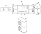
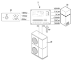
도 1은 일 실시예에 따른 공기조화기의 구성을 도시한 도면이다.1 is a diagram illustrating the configuration of an air conditioner according to an embodiment.
도 1을 참조하면, 공기조화기(1)는 실외 공간에 마련되어 실외 공기와 냉매 사이의 열교환을 수행하는 실외기(20)와, 실내 공간에 마련되어 실내 공기와 냉매 사이에 열교환을 수행하는 실내기(30)를 포함한다. 실외기(20)는 공기 조화 공간 밖에 위치할 수 있으며, 실내기(30)는 공기 조화 공간 내에 위치할 수 있다. 공기 조화 공간은 공기조화기(1)에 의하여 냉방 또는 난방 되는 공간을 의미한다. 예를 들면, 실외기(20)는 건물의 외부에 배치될 수 있고, 실내기(30)는 거실 또는 사무실과 같이 벽에 의하여 외부와 분리된 공간 내에 배치될 수 있다.Referring to FIG. 1, the
전술한 바와 같이, 실외기(20)와 실내기(30)는 외부 배관을 통해 연결될 수 있다. 냉매는 실외기(20), 외부 배관 및 실내기(30)를 통해 순환할 수 있다. 외부 배관의 일 단은 실외기(20)의 일 측에 마련되는 배관 밸브에 연결될 수 있다. 또한, 외부 배관은 실외기(20)와 실내기(30) 내부에 마련되는 냉매관과 연결될 수 있다.As described above, the
냉매는 냉매 유로를 따라 실내기(30)와 실외기(20)를 순환하며, 상태 변화(예를 들어, 기체에서 액체로 상태 변화, 액체에서 기체로 상태 변화)를 통해 열을 흡수하거나 열을 방출할 수 있다. 공기조화기(1)는 실외기(20)와 실내기(30) 사이를 연결하고 액상 냉매가 유동하는 통로가 되는 액관과, 기상 냉매가 유동하는 통로가 되는 가스관을 포함할 수 있다. 액관과 가스관은 실외기(20) 및 실내기(30) 내부로 연장될 수 있다.The refrigerant circulates between the
실외기(20)는 냉매를 압축하는 압축기, 실외 공기와 냉매 사이의 열교환을 수행하는 실외 열교환기, 냉방 운전 또는 난방 운전에 기초하여 압축기에 의해 압축된 냉매를 실외 열교환기 또는 실내 열교환기로 안내하는 사방 밸브(4-way valve), 냉매를 감압하는 팽창 밸브 및 증발되지 못한 액상 냉매가 압축기로 유입되는 것을 방지하는 어큐뮬레이터를 포함할 수 있다.The
압축기는 외부 전원으로부터 전기에너지를 공급받아 동작할 수 있다. 압축기는 압축기 모터를 포함하고, 압축기 모터의 회전력을 이용하여 저압의 기상 냉매를 고압으로 압축한다. 압축기는 실내기(30)에서 요구하는 능력에 대응하도록 운전 주파수를 변경할 수 있다. 압축기는 인버터 공기 압축기(Inverter air compressor), 용적형 압축기 또는 다이나믹형 압축기일 수 있으며, 설계자가 고려할 수 있는 다양한 종류의 압축기가 이용될 수 있다.The compressor can operate by receiving electrical energy from an external power source. The compressor includes a compressor motor, and compresses low-pressure gaseous refrigerant to high pressure using the rotational force of the compressor motor. The compressor can change its operating frequency to correspond to the capacity required by the
실내기(30)는 실내 열교환기와 실내 팬을 포함할 수 있다. 실내 열교환기는 실내 공기와 냉매 사이의 열교환을 수행한다. 실내 팬은 실내 공기를 실내 열교환기로 유동시킬 수 있다. 실내 팬은 복수 개로 마련될 수 있다. 실내 열교환기의 양 측(입구와 출구)에는 실내 열교환기의 온도를 검출하기 위한 실내 열교환기 온도 센서가 마련될 수 있다. 실내 열교환기 온도 센서는 실내 열교환기의 입구 및/또는 출구 주변에 설치되거나, 실내 열교환기의 입구 및/또는 출구와 연결되는 냉매 관에 접촉하도록 설치될 수 있다. 실내기(30) 내부에는 실내 온도를 검출하기 위한 실내 온도 센서가 마련될 수 있다. 온도 센서는 바이메탈 온도계, 서미스터 온도계(thermistor thermometer) 또는 적외선 온도계 중 적어도 하나로 구현될 수 있다. 이외에도, 공기조화기(1)는 다양한 온도 센서를 포함할 수 있다. The
냉방 운전 시, 냉매는 실외기(20)의 실외 열교환기에서 열을 방출하고, 실내기(30)의 실내 열교환기에서 열을 흡수할 수 있다. 냉방 운전 시 실외기(20)의 압축기에서 압축된 냉매는 사방 밸브를 거쳐 실외 열교환기로 먼저 공급되고, 팽창 밸브를 거쳐 실내기(30)의 실내 열교환기로 공급될 수 있다. 냉방 운전 시, 실외 열교환기는 냉매를 응축시키는 응축기로 동작하고, 실내 열교환기는 냉매를 증발시키는 증발기로 동작한다. 냉방 운전 시, 압축기에서 토출되는 고온 고압의 기상 냉매는 실외 열교환기로 이동한다. 실외 열교환기에서 응축된 액상 혹은 액상에 가까운 냉매는 팽창 밸브에서 팽창되어 감압된다. 팽창 밸브를 통과한 이상(Two-phase) 냉매는 실내 열교환기로 이동한다. 실내 열교환기로 유입된 냉매는 주변 공기와 열교환하여 증발된다. 따라서 열교환된 주변 공기의 온도가 내려가고 실내기(30)의 외부로 냉기가 토출된다.During cooling operation, the refrigerant may emit heat from the outdoor heat exchanger of the
난방 운전 시, 냉매는 실내 열교환기에서 열을 방출하고, 실외 열교환기에서 열을 흡수할 수 있다. 즉, 난방 운전 시 압축기에서 압축된 냉매는 사방 밸브를 거쳐 실내 열교환기로 먼저 공급된 후 실외 열교환기로 공급될 수 있다. 이 경우, 실내 열교환기는 냉매를 응축시키는 응축기로 동작하고, 실외 열교환기는 냉매를 증발시키는 증발기로 동작한다. 난방 운전 시, 압축기에서 토출되는 고온 고압의 기상 냉매는 실내 열교환기로 이동한다. 실내 열교환기를 통과하는 고온 고압의 기상 냉매는 저온 건조한 공기와 열교환 한다. 냉매는 액상 혹은 액상에 가까운 냉매로 응축되면서 열을 방출하고, 공기가 열을 흡수함으로써 실내기(30)의 외부로 온기가 토출된다.During heating operation, the refrigerant can emit heat from the indoor heat exchanger and absorb heat from the outdoor heat exchanger. That is, during heating operation, the refrigerant compressed in the compressor may be first supplied to the indoor heat exchanger through a four-way valve and then to the outdoor heat exchanger. In this case, the indoor heat exchanger operates as a condenser that condenses the refrigerant, and the outdoor heat exchanger operates as an evaporator that evaporates the refrigerant. During heating operation, the high-temperature, high-pressure gaseous refrigerant discharged from the compressor moves to the indoor heat exchanger. The high-temperature, high-pressure gaseous refrigerant passing through the indoor heat exchanger exchanges heat with low-temperature, dry air. The refrigerant condenses into a liquid or near-liquid refrigerant and releases heat, and the air absorbs the heat, thereby discharging warmth to the outside of the
공기조화기(1)가 하나의 실외기(20)와 하나의 실내기(30)를 포함하는 것으로 설명되었으나, 복수의 실외기(20) 및 복수의 실내기(30)를 포함할 수도 있다. 예를 들면, 하나의 실외기(20)에 복수의 실내기(30)가 연결될 수 있다. 또한, 실내기(30)의 형태는 설명된 것으로 제한되지 않는다. 실내 공간에 설치되어 실내 공간을 냉방 또는 난방할 수 있는 실내기(30)라면, 어떤 형태의 실내기(30)도 적용될 수 있다.Although the
또한, 공기조화기(1)는 실내 제어기(10) 및 메인 제어기(2)를 포함할 수 있다. 메인 제어기(2)는 실외기(20), 실내기(30) 및 실내 제어기(10)와 전기적으로 연결될 수 있다. 실외기(20), 실내기(30) 및 실내 제어기(10)는 유선으로 메인 제어기(2)와 연결될 수 있다. 실내 제어기(10)는 '접점 제어기'로 호칭될 수도 있다.Additionally, the
실내 제어기(10)는 사용자 입력을 획득할 수 있다. 실내 제어기(10)는 실내 온도 설정 또는 냉난방에 관한 사용자 입력을 획득할 수 있다. 메인 제어기(2)는 실내 제어기(10)로부터 사용자 입력에 대응하는 복수의 제1 신호를 수신할 수 있다.The
메인 제어기(2)는 실외기(20)와 실내기(30)의 동작을 제어할 수 있다. 메인 제어기(2)는 실내 제어기(10)를 통해 입력되는 사용자 입력에 응답하여 실외기(20)와 실내기(30)를 동작시킬 수 있다. 메인 제어기(2)는 수신한 전기적 신호에 기초하여 공기조화기(1)의 동작을 제어할 수 있다.The
메인 제어기(2)는 다양한 실외기(20)를 공기조화기(1)에 연결하는 어댑터 역할을 수행할 수 있다. 메인 제어기(2)는 실외기(20)의 제조사와 동일한 제조사에 의해 생산된 실외기(20)를 제어할 수 있을 뿐만 아니라, 다른 제조사에 의해 생산된 실외기(20) 및/또는 다른 통신 프로토콜을 갖는 실외기(20)까지 제어할 수 있도록 마련된다. The main controller (2) can serve as an adapter to connect various outdoor units (20) to the air conditioner (1). The
도 2는 일 실시예에 따른 공기조화기의 제어 구성을 도시한다.Figure 2 shows the control configuration of an air conditioner according to one embodiment.
도 2를 참조하면, 공기조화기(1)는 메인 제어기(2), 실내기(30), 실외기(20) 및 실내 제어기(10)를 포함할 수 있고, 메인 제어기(2)는 메모리(112)와 프로세서(111)를 포함하는 제어부(110) 및 통신부(100)를 포함할 수 있다. Referring to FIG. 2, the
메인 제어기(2)의 메모리(112)는, 공기조화기(1)의 동작에 필요한 각종 정보를 기억/저장할 수 있다. 메모리(112)는, 공기조화기(1)의 동작에 필요한 인스트럭션, 어플리케이션, 데이터 및/또는 프로그램을 저장할 수 있다. 전술한 바와 같이 메모리(112)는 데이터를 일시적으로 기억하기 위한 S-램(Static Random Access Memory, S-RAM), D-램(Dynamic Random Access Memory) 등의 휘발성 메모리(112)와, 데이터를 장기간 저장하기 위한 롬(Read Only Memory), 이피롬(Erasable Programmable Read Only Memory: EPROM), 이이피롬(Electrically Erasable Programmable Read Only Memory: EEPROM) 등의 비휘발성 메모리(112)를 포함할 수 있다.The
메인 제어기(2)의 프로세서(111)는 메모리(112)에 저장된 인스트럭션, 어플리케이션, 데이터 및/또는 프로그램에 기초하여 공기조화기(1)의 동작을 제어하기 위한 제어 신호를 생성할 수 있다. 프로세서(111)는 하드웨어로서, 논리 회로와 연산 회로를 포함할 수 있다. 프로세서(111)는 메모리(112)로부터 제공된 프로그램 및/또는 인스트럭션에 따라 데이터를 처리하고, 처리 결과에 따라 제어 신호를 생성할 수 있다. 메모리(112)와 프로세서(111)는 하나의 제어 회로로 구현되거나 복수의 회로로 구현될 수 있다.The
메인 제어기(2)는 실내 제어기(10)로부터 전송되는 복수의 제1 신호를 수신하여 실외기(20) 및/또는 실내기(30)의 동작을 결정할 수 있다. 제1 신호는 접점 제어기로부터 발생되는 접점 신호를 포함할 수 있고, 접점 신호는 스위치로 구성되는 접점이 열려 있는지 닫혀 있는지의 상태를 표시하는 신호를 의미한다. The
메인 제어기(2)의 제어부(110)는 수신된 복수의 제1 신호를 조합하여 하나의 제2 신호로 변환하는 신호 변환부를 포함할 수 있다. 이때, 제어부(110)는 복수의 제1 신호 중에서 온(ON) 상태인 신호를 조합하여 제2 신호로 변환할 수 있다. The
제2 신호는 RS 485 통신 규격에 대응되는 RS 485 신호를 포함할 수 있으며, 제1 신호와는 다른 통신 규격을 따르는 통신 신호를 포함할 수 있다.The second signal may include an RS 485 signal that corresponds to the RS 485 communication standard, and may include a communication signal that follows a communication standard different from the first signal.
제어부(110)는 제2 신호를 실외기(20)에 전송하여 실외기(20)의 동작을 결정할 수 있으며, 실외기(20)는 제2 신호에 기초하여 동작할 수 있다. 이에 따라, 일 실시예에 따른 공기조화기(1)는 기존에 사용되던 실외기(20)가 다른 종류의 실외기(20)로 교체되어도 호환성을 보장할 수 있다.The
제어부(110)는 송신 단자와 수신 단자를 포함하는 실외기 연결 단자(21)를 통해 실외기(20)와 양방향 통신할 수 있으며, 구체적으로 제어부(110)는 통신부(100)를 제어하여 송신 단자로 제2 신호를 송신할 수 있고, 수신 단자로부터 실외기(20) 동작에 관한 동작 신호인 제3 신호를 수신할 수 있다. 이에 따라, 제어부(110)는 실외기(20)의 현재 동작 상태와 실외기(20)에서 필요한 제어 동작을 결정할 수 있다. 예를 들어, 제어부(110)는 실외기(20)의 동작 신호에 기초하여 제상 운전으로 진입할지 여부, 냉풍 방지 기능을 수행할지 여부 및 풍량 조절 기능을 수행할지 여부를 결정할 수 있다.The
제어부(110)는 복수의 제1 신호에 기초하여 실내기(30)의 동작을 결정할 수 있고, 결정된 실내기(30)의 동작을 실내기(30)로 전송하도록 통신부(100)를 제어할 수 있다. 구체적으로, 제어부(110)는 복수의 제1 신호에 대응되는 실내기(30)의 운전 모드와 설정 온도를 결정할 수 있다. The
또한 제어부(110)는 복수의 제1 신호 중 적어도 하나의 제1 신호의 전송을 기준 시간 동안 차단하여 실내기(30)의 동작을 결정할 수 있다. 예를 들어, 제어부(110)는 복수의 제1 신호 중에서 실내 팬 신호를 미리 설정된 기준 시간만큼 차단하여 효율적인 제상 운전이 가능하도록 제어할 수 있다. 이에 따라, 실내기(30)가 인버터 실내기(30)가 아닌 이종의 실내기(30)라 하더라도 신호를 일부 지연 혹은 차단하여 공조기 팬, 보조 열원, 기타 공조 장치를 제어할 수 있다. Additionally, the
이때, 실내기(30)의 동작에는 복수의 운전 스테이지 중에서 어느 하나의 운전 스테이지를 선택하는 것이 포함될 수 있으며, 복수의 운전 스테이지에는 미, 약, 강의 냉난방 강도가 포함될 수 있다.At this time, the operation of the
또한, 제어부(110)는 복수의 제1 신호와 실외기(20)로부터 발생한 실외기(20)의 운전 상태에 대응되는 제3 신호에 기초하여 실내 팬을 제어할 수 있다. 이때, 제3 신호에는 풍량 조절 신호, 제상 운전 신호 및 냉풍 방지 신호 중 어느 하나가 포함될 수 있다. Additionally, the
구체적으로 제어부(110)는, 제3 신호가 풍량 조절 신호인 것에 기초하여, 실내 제어기(10)의 오프 신호 출력 횟수와 오프 신호 출력 시간을 조합하여 메인 제어기(2)에 마련된 복수의 풍량 조절 단자 중 실내 팬 제어 신호를 출력하는 풍량 조절 단자를 결정할 수 있다. 즉, 제어부(110)는, 오프 신호 출력 횟수가 기준 횟수 이상이고, 오프 신호 출력 시간이 기준 시간 이상인 것에 기초하여, 실내기(30)의 풍량을 감소시키도록 풍량 조절 단자를 결정할 수 있다.Specifically, based on the fact that the third signal is an air volume control signal, the
또한 제어부는, 제3 신호가 제상 운전 신호인 것에 기초하여, 실내 팬의 오프 신호를 기준 시간 동안 지연하여 출력하고, 실외기(20)로부터 제상 운전이 종료되는 제상 운전 종료 신호가 수신되는 시점보다 기준 시간만큼 미리 실내 팬의 온 신호를 출력할 수 있다.In addition, based on the fact that the third signal is a defrost operation signal, the control unit delays and outputs the off signal of the indoor fan for a reference time, and delays the defrost operation end signal from the
제어부는 제3 신호가 냉풍 방지 신호인 것에 기초하여, 실내 팬의 오프 신호를 기준 시간 동안 지연하여 출력하고, 실외기(20)로부터 난방 운전을 재가동하는 신호가 수신된 것에 기초하여, 압축기의 압력이 기준 압력 이상이 될 때까지 실내 팬의 온 신호를 지연하여 출력할 수 있다.Based on the fact that the third signal is a cold wind prevention signal, the control unit delays the off signal of the indoor fan for a reference time and outputs it, and based on receiving a signal to restart the heating operation from the
메인 제어기(2)의 통신부(100)는 실외기(20), 실내기(30), 및 실내 제어기(10)를 전기적으로 연결하기 위한 회로를 포함할 수 있다. 예를 들면, 통신부(100)는 실내 제어기(10)와 연결되는 복수의 접점 단자들을 포함할 수 있다. 복수의 접점 단자들은 실외기 연결 단자(21), 실내기 연결 단자(31)를 포함할 수 있다.The
또한, 통신부(100)는 실외기(20) 및 실내기(30)와 통신을 수행하기 위한 유선 통신부(102) 및/또는 무선 통신부(101)를 포함할 수 있다. 통신부(100)는 프로세서(111)로부터 전달되는 제어 신호를 실외기(20)와 실내기(30)로 전송하거나, 실외기(20)와 실내기(30)로부터 전송되는 전기적 신호를 프로세서(111)로 전달할 수 있다.Additionally, the
또한, 통신부(100)는 공기 조화 공간에 별도로 마련되는 액세스 포인트(access point, AP)(미도시)와 통신을 수행할 수 있으며, 액세스 포인트를 통하여 네트워크와 연결될 수 있다. 통신부(100)는 액세스 포인트를 통해 외부 장치(예를 들면, 스마트폰)와 통신을 수행할 수 있다. 통신부(100)는 액세스 포인트에 접속된 외부 장치의 정보를 수신할 수 있으며, 외부 장치의 정보를 프로세서(111)로 전달할 수 있다. 이를 통해, 사용자는 공기조화기(1)를 원격으로 제어할 수 있다.Additionally, the
일 실시예에 따른 공기조화기(1)는 원격 제어기(미도시)를 더 포함할 수도 있다. 원격 제어기는 입력부와 디스플레이를 포함할 수 있다. 원격 제어기의 입력부는 사용자 입력을 획득할 수 있고, 사용자 입력에 대응하는 전기적 신호(전압 또는 전류)를 메인 제어기(2)로 출력할 수 있다. 예를 들면, 원격 제어기는 공기조화기(1)를 켜거나 끄기 위한 파워 온오프 입력, 공기조화기(1)의 운전 모드를 설정하기 위한 운전 모드 선택 입력 및/또는 실내 온도를 조절하기 위한 온도 조절 입력을 획득할 수 있다.The
원격 제어기의 입력부는 다양한 버튼들 및/또는 다이얼로 구현될 수 있다. 예를 들면, 복수의 버튼들은 사용자가 누르는 것에 의하여 작동되는 푸시 스위치(push switch), 멤브레인 스위치(membrane switch) 및/또는 사용자의 신체 일부의 접촉에 의하여 작동되는 터치 스위치(touch switch)를 포함할 수 있다. 버튼들은, 냉방 운전, 난방 운전 및 송풍 운전과 같은 운전 모드를 선택하기 위한 운전 모드 버튼, 실내 공간(공조 공간)의 목표 온도를 설정하기 위한 온도 버튼, 바람의 방향을 설정하기 위한 풍향 버튼 및/또는 바람의 세기(실내 팬의 회전 속도)를 설정하기 위한 풍량 버튼을 포함할 수 있다. 이러한 버튼들은 회전 가능한 다이얼로 구현될 수도 있다.The input unit of the remote controller may be implemented with various buttons and/or dials. For example, the plurality of buttons may include a push switch that is activated by a user pressing it, a membrane switch, and/or a touch switch that is activated by contact with a part of the user's body. You can. The buttons include an operation mode button to select operation modes such as cooling operation, heating operation, and blowing operation, a temperature button to set the target temperature of the indoor space (conditioned space), a wind direction button to set the wind direction, and/ Alternatively, it may include a wind volume button to set the wind strength (rotation speed of the indoor fan). These buttons may also be implemented as rotatable dials.
원격 제어기의 디스플레이는 공기조화기(1)의 상태 및/또는 동작에 관한 정보를 표시할 수 있다. 디스플레이는 사용자가 입력한 정보 또는 사용자에게 제공되는 정보를 다양한 화면으로 표시할 수 있다. 디스플레이는 공기조화기(1)의 작동과 관련된 정보를 이미지 또는 텍스트 중 적어도 하나로 표시할 수 있다. 또한, 디스플레이는 공기조화기(1)의 제어를 가능하게 하는 그래픽 사용자 인터페이스(GUI, Graphic User Interface)를 표시할 수 있다. 즉, 디스플레이는 아이콘(Icon)과 같은 UI 엘리먼트(User Interface Element)를 표시할 수 있다.The display of the remote controller may display information regarding the status and/or operation of the
원격 제어기의 디스플레이는 다양한 타입의 디스플레이 패널을 포함할 수 있다. 예를 들어, 디스플레이는 액정 디스플레이 패널(Liquid Crystal Display Panel, LCD Panel), 발광 다이오드 패널(Light Emitting Diode Panel, LED Panel), 유기 발광 다이오드 패널(Organic Light Emitting Diode Panel, OLED Panel), 또는 마이크로 LED 패널을 포함할 수 있다. 디스플레이는 터치 디스플레이로 구현될 수도 있다. 터치 디스플레이는 영상을 표시하는 디스플레이 패널과, 터치 입력을 수신하는 터치 패널을 포함할 수 있다. 디스플레이가 터치 디스플레이로 마련되는 경우, 원격 제어기에 별도의 입력부가 마련되지 않을 수도 있다.The display of the remote controller may include various types of display panels. For example, the display may be a Liquid Crystal Display Panel (LCD Panel), a Light Emitting Diode Panel (LED Panel), an Organic Light Emitting Diode Panel (OLED Panel), or a micro LED. Can include panels. The display may be implemented as a touch display. The touch display may include a display panel that displays an image and a touch panel that receives touch input. When the display is provided as a touch display, a separate input unit may not be provided in the remote controller.
실내 제어기(10)는 사용자 입력을 획득할 수 있다. 예를 들면, 실내 제어기(10)는 운전 모드를 선택하는 운전 모드 선택 입력을 획득할 수 있고, 실내 온도를 설정하기 위한 온도 설정 입력을 획득할 수 있다. 실내 제어기(10)는 원격 제어기와 구별되는 별개의 입력 장치일 수 있다. 실내 제어기(10)는 원격 제어기보다 간단한 구조로 마련될 수 있다. 실내 제어기(10)에 의해 실내 온도 설정 또는 실외기(20)의 전류 설정이 간단하게 입력될 수 있다.The
실내 제어기(10)는 운전 모드 입력부와 조절기를 포함할 수 있다. 운전 모드 입력부와 조절기는 각각 회전 가능한 다이얼로 마련될 수 있다. 운전 모드 입력부와 조절기의 형태는 다이얼로 제한되지 않으며, 다양한 형태로 마련될 수 있다. 운전 모드 입력부와 조절기는 다양한 버튼들을 포함할 수도 있다.The
운전 모드 입력부는 공기조화기(1)의 운전 모드를 선택하도록 마련될 수 있다. 실내 제어기(10)는 운전 모드 입력부의 동작에 대응하는 전기적 신호(운전 모드 선택 신호)를 메인 제어기(2)로 전송할 수 있다. 예를 들면, 공기조화기(1)의 운전 모드는 냉방 운전 모드, 난방 운전 모드 및 자동 운전 모드를 포함할 수 있다. 공기조화기(1)는 운전 모드 입력부의 조작에 따라 선택되는 운전 모드로 동작할 수 있다. 즉, 공기조화기(1)는 냉방 운전, 난방 운전 또는 자동 운전을 수행할 수 있다. 사용자는 운전 모드 입력부를 조작하여 파워 오프, 냉방 운전, 난방 운전 또는 자동 운전을 선택할 수 있다.The operation mode input unit may be provided to select the operation mode of the air conditioner (1). The
공기조화기(1)의 구성 요소들은 전술된 것으로 한정되지 않는다. 전술된 실외기(20)의 구성 요소들 이외에 다른 구성 요소가 추가될 수도 있다.The components of the
도 3은 일 실시예에 따른 메인 제어기를 도시한다.Figure 3 shows a main controller according to one embodiment.
도 3을 참조하면, 메인 제어기(2)는 메인 회로 기판(4)과 복수의 접점 단자들(3)을 포함할 수 있다. 메인 회로 기판(4)에는 메모리(112)와 프로세서(111)가 실장될 수 있다. 프로세서(111)는 '마이콤(Micom)'으로 호칭될 수도 있다. 통신부(100)는 접점 단자들(3) 외에도 다른 장치들과 연결을 위한 단자 블록들을 통해 외부 기기와 통신할 수 있다.Referring to FIG. 3, the
복수의 접점 단자들(3)에는 실외기(20), 실내기(30) 및 실내 제어기(10)가 연결될 수 있다. 접점 단자들(3)과 실외기(20), 실내기(30) 및 실내 제어기(10) 각각은 전선 및/또는 케이블로 연결될 수 있다.The
예를 들어, 실외기(20)는 접점 단자들(3) 중 F1 단자와 F2 단자에 연결될 수 있다. 메인 제어기(2)는 F1 단자와 F2 단자를 통해 실외기(20)와 통신할 수 있다. 예를 들면, 메인 제어기(2)의 프로세서(111)에 의해 생성되는 신호는 F1, F2 단자를 통해 실외기(20)로 전송될 수 있고, 실외기(20)에 의해 생성되는 신호는 F1, F2 단자를 통해 프로세서(111)로 전송될 수 있다.For example, the
실내기(30)는 접점 단자들(3) 중 TR 단자, TEI 단자 및 TEO 단자에 연결될 수 있다. 전술한 바와 같이, 실내기(30)는 실내 온도 센서와 실내 열교환기 온도 센서를 포함할 수 있다. 실내기(30)의 실내 온도 센서에 의해 생성되는 신호는 TR 단자를 통해 메인 제어기(2)의 프로세서(111)로 입력될 수 있다. 실내기(30)의 실내 열교환기 온도 센서에 의해 생성되는 신호는 TEI 단자 및 TEO 단자를 통해 메인 제어기(2)의 프로세서(111)로 입력될 수 있다.The
원격 제어기는 접점 단자들(3) 중 F3 단자와 F4 단자에 연결될 수 있다. 메인 제어기(2)는 F3 단자와 F4 단자를 통해 원격 제어기와 통신할 수 있다. 예를 들면, 메인 제어기(2)의 프로세서(111)에 의해 생성되는 신호는 F3, F4 단자를 통해 원격 제어기로 전송될 수 있고, 원격 제어기에 의해 생성되는 신호는 F3, F4 단자를 통해 프로세서(111)로 전송될 수 있다.The remote controller may be connected to terminals F3 and F4 of the contact terminals 3. The
실내 제어기(10)는 접점 단자들(3) 중 COM 단자, AUT 단자, HP 단자, CO 단자, AV1 단자 및 AV2 단자에 연결될 수 있다. COM 단자, AUT 단자, HP 단자 및 CO 단자는 실내 제어기(10)의 운전 모드 입력부와 연결될 수 있다. COM 단자는 공통 단자를 의미할 수 있고, AUT 단자에는 오토(Auto) 운전 신호가 입력될 수 있고, HP 단자에는 난방 운전 신호가 입력될 수 있으며, CO 단자에는 냉방 운전 신호가 입력될 수 있다. 운전 모드 입력부의 동작에 따라 AUT 단자, HP 단자 및 CO 단자 중 하나로 신호가 입력될 수 있다.The
AV1 단자 및 AV2 단자는 실내 제어기(10)의 조절기와 연결될 수 있다. AV1 단자는 제1 접점 단자로 호칭될 수 있고, AV2 단자는 제2 접점 단자로 호칭될 수 있다. 조절기의 동작에 따라 제1 접점 단자(AV1 단자)에 인가되는 신호의 전압이 달라질 수 있다. 다시 말해, 조절기의 동작에 따라 제1 접점 단자(AV1 단자)와 제2 접점 단자(AV2) 사이에 걸리는 전압이 달라질 수 있다. 메인 제어기(2)는 제1 접점 단자(AV1 단자)에 인가되는 신호의 전압에 기초하여, 실내 공간에 관한 목표 온도 또는 실외기(20)에 인가되는 최대 전류를 결정할 수 있다. The AV1 terminal and AV2 terminal can be connected to the regulator of the
도 4는 일 실시예에 따른 공기조화기에서 메인 제어기와 공기조화기의 구성 간 연결을 도시한다.Figure 4 shows the connection between the main controller and the components of the air conditioner in the air conditioner according to one embodiment.
도 4를 참조하면, 종래 기술과 다르게 실내 제어기(10)의 접점 신호 라인이 메인 제어기(2)에 연결될 수 있다. 구체적으로, 압축기 및 팬 출력을 제어하기 위한 제1 압축기 단자(Y1), 압축기 및 팬 출력을 보다 세밀하게 조정하기 위한 제2 압축기 단자(Y2), 제1 보조열원을 제어하기 위한 제1 보조 열원 단자(W1), 제2 보조열원을 제어하기 위한 제2 보조 열원 단자(W2), 실내 팬을 제어하기 위한 팬 단자(G) 및 사방밸브를 제어하기 위한 사방밸브 단자(O/B) 등이 실내기(30)나 실외기(20)에 직접 연결되지 않고, 메인 제어기(2)에 연결될 수 있다.Referring to FIG. 4, unlike the prior art, the contact signal line of the
메인 제어기(2)에서는 실내 제어기(10)에서 수신된 제1 신호를 변환하여 제2 신호를 생성하고, 제2 신호를 실외기(20)에 전송할 수 있고, 제1 신호를 지연시키거나 차단하여 실내기(30)의 동작을 세밀하게 제어할 수 있다.The
이에 따라, 종래에는 실내 제어기(10)와 통신 방식이 다른 실외기(20)는 설치될 수 없었으나, 일 실시예에 따른 공기조화기(1)에 의하면 통신 방식이 다른 실외기(20)라도 메인 제어기(2)에서 통신 방식에 맞게 신호를 변환하므로 통신 방식이 다른 실외기(20)를 사용할 수 있다. 또한, 종래에는 접점 통신 방식에 의해 공조기 팬, 보조 열원 및 기타 공조 장치를 세밀하게 제어할 수 없었으나, 메인 제어기(2)의 신호 차단 또는 지연에 기초하여 세밀한 제어가 가능하다.Accordingly, conventionally, an
구체적으로, 실내 제어기(10), 실내기(30)는 접점 방식의 제1 통신 방식에 의해 제1 신호를 송수신 할 수 있으나, RS 485 방식의 제2 통신 방식은 지원하지 않을 수 있다. 또한, 실외기(20)는 RS 485 방식의 제2 통신 방식으로 제2 신호를 수신할 수 있으나, 접점 방식의 제1 통신 방식을 지원하지 않을 수 있다. 여기에서 통신 방식을 지원한다는 의미는 해당 통신 방식으로 통신하기 위한 연결 단자 및 신호 처리 회로를 구비하고 있음을 의미하고, 해당 통신 방식으로 신호의 송수신이 가능한 것을 의미할 수 있다.Specifically, the
도 5 이하에서 메인 제어기(2)에 의해 해결할 수 있는 기술적 과제에 대해 구체적으로 설명한다.5 and below, technical problems that can be solved by the
도 5는 일 실시예에 따른 메인 제어기에 의해 제상 운전이 제어되는 과정을 도시한다.Figure 5 shows a process in which the defrost operation is controlled by the main controller according to one embodiment.
도 5를 참조하면, 메인 제어기(2)의 제어부(110)는 실내 제어기(10)에서 접점 신호인 복수의 제1 신호를 수신하고, 일부 신호를 지연하거나 차단하여 종래의 접점 신호로는 제어할 수 없었던 기능을 제어할 수 있다.Referring to FIG. 5, the
일 실시예에 따른 메인 제어기(2)의 제어부(110)는 실외기(20)로부터 실외기(20) 제상 신호를 수신하고, 이에 기초하여 제상 운전으로 진입(a)할 수 있다. 종래 기술과 다르게 제어부(110)는 실외기(20) 제상 신호를 수신한 시점에 제1 압축기 단자(Y1), 제2 압축기 단자(Y2), 제1 보조 열원 단자(W1), 제2 보조 열원 단자(W2), 사방밸브 단자(O/B) 및 실내 팬 단자(G)의 신호를 오프(OFF) 상태로 제어할 수 있다.The
이때, 제어부(110)는 실내 팬 단자(G)를 다른 단자보다 미리 설정된 시간 만큼 늦게 오프(OFF) 상태로 변경(b)시키고, 다른 단자 보다 미리 설정된 시간 만큼 일찍 온(ON) 상태로 변경(c)시킬 수 있다.At this time, the
제상 운전은 실외기(20) 주변의 온도가 하락하여 발생하는 성애를 제거하기 위한 운전으로, 냉방 운전 원리에 따라 실외기(20) 표면의 성애를 녹이는 과정에 해당한다. 따라서, 제어부(110)는 난방 운전 중 제상 운전으로 돌입하면 제상중 찬바람이 실내로 유출되는 것을 방지 하기 위해 메인 제어기에서 공기 조화기(1)로 출력 되는 접점 신호를 차단 하여 공기 조화기(1) 및 기타 장치들을 제상 운전중 정지 시킬수 있으며 제상 진입시 실내 팬 신호(G)가 오프상태로 전환되는 것을 다른 신호보다 지연시켜 공기조화기(1) 내부의 잔열을 제거할 수 있다. 이후, 제어부(110)는 제상운전이 종료(c)되면 실내 팬신호 출력후 기타 신호를 지연 출력하여 열교환기 및 히터 동작시 과열을 방지 할수 있다. 이때, 제어부(110)가 실내 팬 신호(G)를 지연 출력하거나 미리 출력하는 기준 시간은 공기조화기(1)의 설계자에 의해 미리 정해지거나, 사용자에 의해 설정될 수 있다.The defrost operation is an operation to remove frost generated by a drop in temperature around the
위와 같이, 일 실시예에 따른 공기조화기(1)에 의하면, 종래 접점 방식의 공기조화기(1)에서는 제공할 수 없었던 실내기(30)의 기능을 제공할 수 있으므로 사용자의 편의성이 증대되는 효과가 있다.As above, according to the
도 6은 일 실시예에 따른 메인 제어기에 의해 냉풍 방지 기능이 제어되는 과정을 도시한다.Figure 6 shows a process in which the cold wind prevention function is controlled by the main controller according to one embodiment.
도 6을 참조하면, 제어부(110)는 실내 제어기(10)에서 수신된 복수의 제1 신호를 지연하거나 차단하여 냉풍 방지 기능을 제공할 수 있다.Referring to FIG. 6, the
사용자가 공기조화기(1)의 전원을 연결하여 난방 운전으로 작동시키는 경우, 압축기의 주파수가 점진적으로 증가되므로, 작동 초기에는 찬 바람이 실내로 유입될 수 있다. 이에 따라 제어부(110)는 압축기의 압력이 목표 압력에 도달하기 전까지는 실내 팬 단자(G)의 신호를 오프 상태로 제어할 수 있고, 이에 따라 난방 작동 초기에 실내로 찬바람이 유입되는 것을 방지할 수 있다.When a user connects the power to the
구체적으로, 제상 운전 신호가 수신되는 경우와 같이 난방을 정지(a)해야 하는 상황이 발생하면 제어부(110)는 제1 압축기 단자(Y1), 제2 압축기 단자(Y2), 제1 보조 열원 단자(W1), 제2 보조 열원 단자(W2), 사방밸브 단자(O/B) 및 실내 팬 단자(G)의 신호를 오프(OFF) 상태로 제어할 수 있다. 이때, 도 5에서 설명한 바와 같이, 제어부는 공기조화기 내부의 잔열을 제거하기 위해 실내 팬 단자(G)의 신호를 미리 설정된 기준 시간 동안 지연시킨 후에 오프 신호를 출력할 수 있다.Specifically, when a situation in which heating must be stopped (a) occurs, such as when a defrost operation signal is received, the
종래 기술에서는 난방을 재기동(b) 해야 하는 상황이 발생하면 곧바로 실내 팬 출력 신호를 온(ON) 상태로 변경하도록 제어하였다. In the prior art, when a situation requiring heating to be restarted (b) occurs, the indoor fan output signal is controlled to be immediately changed to the ON state.
그러나, 본 개시에서는 난방을 재기동(b) 해야 하는 상황이 발생하면 제어부(110)가 압축기의 압력 (Pc)이 미리 설정된 설계 압력에 도달(c)할 때까지 실내 팬 단자(G)의 신호를 오프(OFF) 상태로 제어하고, 압축기의 압력(Pc)이 미리 설정된 설계 압력에 도달(c)하면 실내 팬 단자(G)의 신호를 온(ON) 상태로 제어(e)할 수 있다. 이에 따라, 압축기의 압력이 설계 압력에 도달할 때 까지는 실내에 바람이 유입되지 않도록 제어하여 난방시 실내에 찬 공기가 유입되는 것을 방지할 수 있다.However, in the present disclosure, when a situation in which heating must be restarted (b) occurs, the
제어부(110)는 실내 팬이 동작을 시작한 후 추가적인 지연 시간(d)을 두어 제1 압축기 단자(Y1), 제2 압축기 단자 (Y2), 제1 보조 열원 단자(W1), 제2 보조 열원 단자(W2) 및 사방밸브 단자(O/B)의 신호를 온(ON)으로 제어할 수 있고, 이에 따라 충분한 풍량을 확보한 상태로 보조 열원을 동작할 수 있다.The
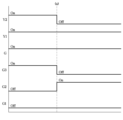
도 7은 일 실시예에 따른 메인 제어기에 의해 풍량이 약풍으로 제어되는 과정을 도시하고, 도 8은 일 실시예에 따른 공기조화기에서 실외기로부터 약풍 신호가 출력되는 것을 도시한다.FIG. 7 shows a process in which the air volume is controlled to be a weak wind by the main controller according to an embodiment, and FIG. 8 shows a weak wind signal being output from the outdoor unit in the air conditioner according to an embodiment.
도7과 도8을 함께 참조하면, 일 실시예에 따른 공기조화기(1)의 메인 제어기(2)에는 풍량 제어를 위해 실내 팬 단자(G)에 더하여, 강풍 단자(G3), 약풍 단자(G2) 및 미풍 단자(G1)의 추가적인 단자가 마련될 수 있다. 이에 따라, 종래의 접점 통신 방식의 공기 조화기에서는 풍량 제어가 불가능 하였으나 본 개시에 의하면 접점 통신 방식에 의한 공기조화기(1)에서 풍량을 제어할 수 있다.Referring to Figures 7 and 8 together, the main controller (2) of the air conditioner (1) according to one embodiment includes an indoor fan terminal (G), a strong wind terminal (G3), and a weak wind terminal ( Additional terminals of G2) and breeze terminal (G1) may be provided. Accordingly, it was impossible to control the air volume in the conventional air conditioner using the contact communication method, but according to the present disclosure, the air volume can be controlled in the
도7과 도8에서는 공기조화기(1)의 냉방 과정에서 풍량이 강풍에서 약풍으로 제어되는 실시예를 도시하였으나, 난방 과정에서는 제1 압축기 단자(Y1) 및 제2 압축기 단자(Y2)가 제1 보조 열원 단자(W1), 제2 보조 열원 단자(W2)로 대체되어 동일하게 동작될 수 있다.7 and 8 show an embodiment in which the air volume is controlled from strong wind to weak wind during the cooling process of the air conditioner (1), but in the heating process, the first compressor terminal (Y1) and the second compressor terminal (Y2) are The first auxiliary heat source terminal (W1) can be replaced with the second auxiliary heat source terminal (W2) and operate in the same manner.
도7을 참조하면, 제어부(110)는 냉방 초기 단계에서는 냉방 강풍으로 설정하여 제1 압축기 단자 (Y1), 제2 압축기 단자 (Y2), 실내 팬 단자(G) 및 강풍 단자(G3)의 신호를 온(ON) 상태로 제어하여 최대 가동 능력으로 냉방을 제공할 수 있다.Referring to Figure 7, the
이후, 도 8에서와 같이 실외기(20)에서는 약풍 신호(a)를 출력할 수 있다. 실외기(20)는 강풍으로 동작하고 미리 설정된 시간이 경과하거나, 실외기(20)에 가해지는 부하에 기초하여 약풍 신호(a)를 메인 제어기(2)에 송신할 수 있다.Thereafter, as shown in FIG. 8, the
이후 메인 제어기(2)는 실외기(20)의 약풍 신호(a)에 기초하여, 실내 제어기(10)의 오프 신호 출력 횟수와 오프 신호 출력 시간을 조합하여 메인 제어기(2)에 마련된 복수의 풍량 조절 단자 중 실내 팬 제어 신호를 출력하는 풍량 조절 단자를 결정할 수 있다.Thereafter, the
예를 들어, 메인 제어기(2)는 강풍 설정 시간 내에 실내 제어기(10)로부터 미리 설정한 기준 횟수인 3회 이상 실외(30)기 및 실내기(30)의 오프(OFF) 신호가 수신되면, 냉방 능력이 충분한 것으로 판단하여 풍량을 약풍으로 변경할 수 있다. 즉, 메인 제어기(2)는 실내기(30)의 풍량을 약풍으로 변경하기 위해 약풍 단자(G2)의 신호를 온(ON)상태로 제어할 수 있다. 또한, 메인 제어기(2)는 실내기(30)가 약풍으로 운전될 수 있도록 제2 압축기 단자(Y2) 및 강풍 단자(G3)의 신호를 오프(OFF)상태로 제어할 수 있다.For example, when the
이를 통해 일 실시예에 따른 공기조화기(1)는 정지 없이 강풍에서 약풍으로 풍량을 가변할 수 있으므로 효율성이 증대되는 효과가 있다.Through this, the
도 9는 일 실시예에 따른 메인 제어기에 의해 풍량이 미풍으로 제어되는 과정을 도시하고, 도 10은 일 실시예에 따른 공기조화기에서 실외기로부터 미풍 신호가 출력되는 것을 도시한다.FIG. 9 shows a process in which air volume is controlled to be a breeze by a main controller according to an embodiment, and FIG. 10 shows a breeze signal being output from an outdoor unit in an air conditioner according to an embodiment.
전술한 바와 같이, 도9와 도10에서는 공기조화기(1)의 냉방 과정에서 풍량이 약풍에서 미풍으로 제어되는 실시예를 도시하였으나, 난방 과정에서는 제1 압축기 단자(Y1) 및 제2 압축기 단자(Y2)가 제1 보조 열원 단자(W1), 제2 보조 열원 단자(W2) 로 대체되어 동일하게 동작될 수 있다.As described above, Figures 9 and 10 show an embodiment in which the air volume is controlled from a weak wind to a light breeze during the cooling process of the air conditioner (1), but during the heating process, the first compressor terminal (Y1) and the second compressor terminal (Y2) can be replaced with the first auxiliary heat source terminal (W1) and the second auxiliary heat source terminal (W2) and operate in the same manner.
도9를 참조하면, 제어부(110)는 냉방 강풍에서 냉방 약풍으로 설정하여 제1 압축기 단자 (Y1), 제2 압축기 단자(Y2), 실내 팬 단자(G), 약풍 단자(G2)의 신호를 온(ON) 상태로 제어하여 약풍으로 냉방을 제공할 수 있다.Referring to Figure 9, the
이후, 도 10에서와 같이 실외기(20)에서는 미풍 신호(a)를 출력할 수 있다. 실외기(20)는 약풍으로 동작하고 미리 설정된 시간이 경과하거나, 실외기(20)에 가해지는 부하에 기초하여 미풍 신호(a)를 메인 제어기(2)에 송신할 수 있다.Afterwards, as shown in FIG. 10, the
이후 메인 제어기(2)는 실외기(20)의 미풍 신호(a)에 기초하여, 실내 제어기(10)의 오프 신호 출력 횟수와 오프 신호 출력 시간을 조합하여 메인 제어기(2)에 마련된 복수의 풍량 조절 단자 중 실내 팬 제어 신호를 출력하는 풍량 조절 단자를 결정할 수 있다.Thereafter, the
예를 들어, 메인 제어기(2)는 약풍 설정 시간 내에 실내 제어기(10)로부터 미리 설정한 기준 횟수인 2회 이상 실외기(20) 및 실내기(30)의 오프(OFF) 신호가 수신되면, 약풍으로 제공되던 냉방 능력이 충분한 것으로 판단하여 풍량을 미풍으로 변경할 수 있다. 즉, 메인 제어기(2)는 실내기(30)의 풍량을 미풍으로 변경하기 위해 미풍 단자(G1)의 신호를 온(ON)상태로 제어할 수 있다. 또한, 메인 제어기(2)는 실내기(30)가 미풍으로 운전될 수 있도록 제2 압축기 단자(Y2), 제1 압축기 단자(Y1) 및 약풍 단자(G2)의 신호를 오프(OFF)상태로 제어할 수 있다.For example, when the
이를 통해 일 실시예에 따른 공기조화기(1)는 정지 없이 약풍에서 미풍으로 풍량을 가변할 수 있으므로 효율성이 증대되는 효과가 있다.Through this, the
도 11은 일 실시예에 따른 공기조화기에서 제2 신호가 제상 운전 진입 신호를 포함하는 경우의 제어 흐름도를 도시한다.Figure 11 shows a control flowchart when the second signal includes a defrost operation start signal in an air conditioner according to an embodiment.
도 11을 참조하면, 사용자는 실내 제어기(10)에 운전 명령에 대응되는 사용자 명령을 입력할 수 있다(1100). 실내 제어기(10)는 사용자 입력에 대응되는 복수의 제1 신호를 발생시키고, 메인 제어기는 복수의 제1 신호를 수신할 수 있다(1110).Referring to FIG. 11, a user can input a user command corresponding to a driving command into the indoor controller 10 (1100). The
또한, 메인 제어기(2)는 실외기 운전 정보에 대응되는 제2신호를 실외기로부터 수신할 수 있다(1120). 이때, 제어부(110)는 제2 신호의 종류에 따라 실외기(20) 및 실내기(30)의 제어를 다르게 할 수 있으므로, 제2신호가 제상 운전 진입 신호를 포함하는지 판단할 수 있다(1130).Additionally, the
제어부(110)는 제2 신호가 제상 운전 진입 신호를 포함하는 것으로 판단되면(1130의 예), 복수의 입력 신호 중 실내 팬 오프 신호를 기준 시간 만큼 지연하여 출력할 수 있다(1140). 이에 따라, 난방 운전 중이던 공기조화기(1) 내부의 잔열이 제거될 수 있다If it is determined that the second signal includes the defrost operation start signal (Yes in 1130), the
이후 제어부(110)는 제상 운전에 따라 공기조화기(1) 내부의 열교환기, 히터등의 발열체의 과열을 방지하기 위해 제상 운전 완료시 복수의 입력 신호 중 실내 팬의 온 신호만을 출력 후 기타 온 신호를 기준 시간 만큼 지연 출력할 수 있다(1150). Afterwards, in order to prevent overheating of heating elements such as the heat exchanger and heater inside the air conditioner (1) according to the defrosting operation, the
도 12는 일 실시예에 따른 공기조화기에서 제2 신호가 냉풍 방지 신호를 포함하는 경우의 제어 흐름도를 도시한다.FIG. 12 shows a control flowchart when the second signal includes a cold wind prevention signal in an air conditioner according to an embodiment.
도 12을 참조하면, 사용자는 실내 제어기(10)에 운전 명령에 대응되는 사용자 명령을 입력할 수 있다(1200). 실내 제어기(10)는 사용자 입력에 대응되는 복수의 제1 신호를 발생시키고, 메인 제어기는 복수의 제1 신호를 수신할 수 있다(1210).Referring to FIG. 12, the user can input a user command corresponding to the driving command into the indoor controller 10 (1200). The
또한, 메인 제어기(2)는 실외기 운전 정보에 대응되는 제2 신호를 실외기로부터 수신할 수 있다(1220). 이때, 제어부(110)는 제2 신호의 종류에 따라 실외기(20) 및 실내기(30)의 제어를 다르게 할 수 있으므로, 제2 신호가 냉풍 방지 신호를 포함하는지 판단할 수 있다(1230).Additionally, the
제어부(110)는 제2 신호가 냉풍 방지 신호를 포함하는 것으로 판단되면(1230의 예), 복수의 입력 신호를 냉풍 방지가 신호가 완료 될 때 까지 오프 되도록, 복수의 입력 신호를 오프 신호로 출력할 수 있다 (1240). If the
이후 제어부(110)는 복수의 입력 신호 중 실내 팬의 온 신호를 설계 압력이 도달한 후 출력하고, 복수의 입력 신호의 오프 신호가 출력된 뒤 기준 시간 이후에 기타 신호의 온 신호를 출력할 수 있다(1250), 이에 따라, 난방 운전 가동 또는 재진입 시에 찬 공기가 실내로 진입하는 것을 방지할 수 있다. Thereafter, the
도 13은 일 실시예에 따른 공기조화기에서 제2 신호가 풍량 조절 신호를 포함하는 경우의 제어 흐름도를 도시한다.Figure 13 shows a control flowchart when the second signal includes an air volume control signal in an air conditioner according to an embodiment.
도 13을 참조하면, 사용자는 실내 제어기(10)에 운전 명령에 대응되는 사용자 명령을 입력할 수 있다(1300). 실내 제어기(10)는 사용자 입력에 대응되는 복수의 제1 신호를 발생시키고, 메인 제어기는 복수의 제1 신호를 수신할 수 있다(1310).Referring to FIG. 13, the user can input a user command corresponding to the driving command into the indoor controller 10 (1300). The
또한, 메인 제어기(2)는 실외기 운전 정보에 대응되는 제2 신호를 실외기로부터 수신할 수 있다(1320). 이때, 제어부(110)는 제2 신호의 종류에 따라 실외기(20) 및 실내기(30)의 제어를 다르게 할 수 있으므로, 제2 신호가 풍량 제어 신호를 포함하는지 판단할 수 있다(1330).Additionally, the
제어부(110)는 제2 신호가 풍량 제어 신호를 포함하는 것으로 판단되면(1230의 예), 복수의 입력 신호 중 제2 신호에 대응되는 신호의 온/오프를 변경할 수 있다(1340).If it is determined that the second signal includes an air volume control signal (Yes in 1230), the
구체적으로, 현재 실내기(30)의 운전 상태가 강풍이면, 실외기(20)의 약풍 신호에 기초하여 강풍 단자(G3)의 온(ON) 신호를 오프(OFF) 신호로 변경하고, 약풍 단자(G2)의 오프(OFF) 신호를 온(ON) 신호로 변경할 수 있다. 마찬가지로, 현재 실내기(30)의 운전 상태가 약풍이면 실외기(20)의 미풍 신호에 기초하여 약풍 단자(G2)의 온(ON) 신호를 오프(OFF) 신호로 변경하고, 미풍 단자(G2)의 오프(OFF) 신호를 온(ON) 신호로 변경할 수 있다.Specifically, if the current operating state of the
이처럼, 일 실시예에 따른 공기조화기(1)는 복수의 제1 신호를 하나의제2 신호로 변환하여 기존 정속형 공조기에 메인 제어기(2)를 통한 인버터 실외기(20) 연결을 가능하게 하여 정속 제품의 호환성과 인버터 제품의 효율성을 모두 만족시킬 수 있는 효과가 있고, 실외기의 상태에 기초하여 실내 팬, 보조 열원, 기타 공조 장치를 제어할 수 있으므로 사용자의 편의성이 증대되는 효과가 있다. In this way, the air conditioner (1) according to one embodiment converts a plurality of first signals into one second signal, enabling connection of the inverter outdoor unit (20) to an existing constant speed air conditioner through the main controller (2). It has the effect of satisfying both the compatibility of constant-speed products and the efficiency of inverter products, and has the effect of increasing user convenience because indoor fans, auxiliary heat sources, and other air conditioning devices can be controlled based on the status of the outdoor unit.
일 실시예에 따른 공기조화기(1)에 의하면, 사용자로부터 운전 명령을 입력 받고, 상기 운전 명령에 대응되는 복수의 제1 신호를 발생시키는 실내 제어기(10), 상기 실내 제어기(10)와 연결되어 상기 복수의 제1 신호를 수신하고, 상기 복수의 제1 신호를 조합하여 하나의 제2 신호로 변환하는 메인 제어기(2), 상기 메인 제어기(2)와 연결되어 상기 메인 제어기(2)로부터 수신된 상기 하나의 제2 신호에 기초하여 동작하고, 실외기(20) 운전 상태에 대응되는 제3 신호를 발생시키는 실외기(20) 및 상기 메인 제어기(2)와 연결되어 실내 팬이 마련되는 실내기(30)를 포함하고, 상기 메인 제어기(2)는, 상기 복수의 제1 신호와 상기 제3 신호에 기초하여 상기 실내 팬을 제어한다.According to the air conditioner (1) according to one embodiment, an indoor controller (10) that receives an operation command from a user and generates a plurality of first signals corresponding to the operation command, and is connected to the indoor controller (10). A main controller (2) that receives the plurality of first signals, combines the plurality of first signals and converts them into one second signal, and is connected to the main controller (2) and receives the plurality of first signals from the main controller (2). An
상기 제3 신호는, 풍량 조절 신호, 제상 운전 신호 및 냉풍 방지 신호 중 어느 하나를 포함할 수 있다.The third signal may include any one of an air volume control signal, a defrost operation signal, and a cold wind prevention signal.
상기 메인 제어기(2)는, 상기 제3 신호가 풍량 조절 신호인 것에 기초하여, 상기 실내 제어기(10)의 오프 신호 출력 횟수와 오프 신호 출력 시간을 조합하여 상기 메인 제어기(2)에 마련된 복수의 풍량 조절 단자 중 실내 팬 제어 신호를 출력하는 풍량 조절 단자를 결정할 수 있다.Based on the fact that the third signal is an air volume control signal, the
상기 메인 제어기(2)는, 상기 오프 신호 출력 횟수가 기준 횟수 이상이고, 상기 오프 신호 출력 시간이 기준 시간 이상인 것에 기초하여, 상기 실내기(30)의 풍량을 감소시키도록 상기 풍량 조절 단자를 결정할 수 있다.The
상기 메인 제어기(2)는, 상기 제3 신호가 제상 운전 신호인 것에 기초하여, 상기 실내 팬의 오프 신호를 기준 시간 동안 지연하여 출력할 수 있다.The
상기 메인 제어기(2)는, 상기 실외기(20)로부터 상기 제상 운전이 종료되는 제상 운전 종료 신호가 수신되는 시점에 팬신호를 출력하고 설정된 시간만큼 지연하여 기타 신호를 출력할 수 있다.The
상기 메인 제어기(2)는, 상기 제3 신호가 냉풍 방지 신호인 것에 기초하여, 복수의 신호를 냉풍 방지 완료 신호를 수신 할 때 까지 출력을 지연 시킬수 있다.Based on the fact that the third signal is a cold wind prevention signal, the
상기 메인 제어기(2)는, 상기 실외기(20)로부터 난방 운전을 재가동하는 신호가 수신된 것에 기초하여, 압축기의 압력이 기준 압력 이상이 될 때까지 복수의 신호를 지연하여 출력할 수 있다.The
일 실시예에 따른 공기조화기(1)의 제어 방법은, 실내 제어기(10)가 사용자로부터 운전 명령을 입력 받아 상기 운전 명령에 대응되는 복수의 제1 신호를 발생시키고, 메인 제어기(2)가 상기 실내 제어기(10)와 연결되어 상기 복수의 제1 신호를 수신하고, 상기 복수의 제1 신호를 조합하여 하나의 제2 신호로 변환하고, 실외기(20)가 상기 메인 제어기(2)와 연결되어 상기 메인 제어기(2)로부터 수신된 상기 하나의 제2 신호에 기초하여 동작하고, 실외기(20) 운전 상태에 대응되는 제3 신호를 발생시키고, 상기 복수의 제1 신호와 상기 제3 신호에 기초하여 상기 실내 팬을 제어하는 것을 포함한다.In the control method of the air conditioner (1) according to one embodiment, the indoor controller (10) receives an operation command from a user and generates a plurality of first signals corresponding to the operation command, and the main controller (2) Connected to the
상기 제3 신호는, 풍량 조절 신호, 제상 운전 신호 및 냉풍 방지 신호 중 어느 하나를 포함할 수 있다.The third signal may include any one of an air volume control signal, a defrost operation signal, and a cold wind prevention signal.
일 실시예에 따른 공기조화기(1)의 제어 방법은, 상기 제3 신호가 풍량 조절 신호인 것에 기초하여, 상기 실내 제어기(10)의 오프 신호 출력 횟수와 오프 신호 출력 시간을 조합하여 상기 메인 제어기(2)에 마련된 복수의 풍량 조절 단자 중 실내 팬 제어 신호를 출력하는 풍량 조절 단자를 결정하는 것을 더 포함할 수 있다.The control method of the air conditioner (1) according to one embodiment is based on the fact that the third signal is an air volume control signal, and the main It may further include determining an air volume control terminal that outputs an indoor fan control signal among a plurality of air volume control terminals provided in the
상기 풍량 조절 단자를 결정하는 것은, 상기 오프 신호 출력 횟수가 기준 횟수 이상이고, 상기 오프 신호 출력 시간이 기준 시간 이상인 것에 기초하여, 상기 실내기(30)의 풍량을 감소시키도록 상기 풍량 조절 단자를 결정할 수 있다.Determining the air volume control terminal determines the air volume control terminal to reduce the air volume of the
일 실시예에 따른 공기조화기(1)의 제어 방법은, 상기 제3 신호가 제상 운전 신호인 것에 기초하여, 상기 실내 팬의 오프 신호를 기준 시간 동안 지연하여 출력하는 것을 더 포함할 수 있다.The control method of the
일 실시예에 따른 공기조화기(1)의 제어 방법은, 상기 실외기(20)로부터 상기 제상 운전이 종료되는 제상 운전 종료 신호가 수신되는 시점보다 상기 기준 시간만큼 미리 상기 실내 팬의 온 신호를 출력하는 것을 더 포함할 수 있다.The control method of the
일 실시예에 따른 공기조화기(1)의 제어 방법은, 상기 제3 신호가 냉풍 방지 신호인 것에 기초하여, 상기 실내 팬의 오프 신호를 기준 시간 동안 지연하여 출력하는 것을 더 포함할 수 있다.The control method of the
상기 실내 팬의 오프 신호를 지연하여 출력하는 것은, 상기 실외기(20)로부터 난방 운전을 재가동하는 신호가 수신된 것에 기초하여, 압축기의 압력이 기준 압력 이상이 될 때까지 상기 실내 팬의 온 신호를 지연하여 출력하는 것을 더 포함할 수 있다.Delaying the output of the off signal of the indoor fan is based on receiving a signal to restart the heating operation from the
한편, 개시된 실시예들은 컴퓨터에 의해 실행 가능한 명령어를 저장하는 저장매체의 형태로 구현될 수 있다. 명령어는 프로그램 코드의 형태로 저장될 수 있으며, 프로세서(111)에 의해 실행되었을 때, 프로그램 모듈을 생성하여 개시된 실시예들의 동작을 수행할 수 있다.Meanwhile, the disclosed embodiments may be implemented in the form of a storage medium that stores instructions executable by a computer. Instructions may be stored in the form of program code, and when executed by the
기기로 읽을 수 있는 저장매체는, 비일시적(non-transitory) 저장매체의 형태로 제공될 수 있다. 여기서, '비일시적 저장매체'는 실재(tangible)하는 장치이고, 신호(signal)(예: 전자기파)를 포함하지 않는다는 것을 의미할 뿐이며, 이 용어는 데이터가 저장매체에 반영구적으로 저장되는 경우와 임시적으로 저장되는 경우를 구분하지 않는다. 예로, '비일시적 저장매체'는 데이터가 임시적으로 저장되는 버퍼를 포함할 수 있다.A storage medium that can be read by a device may be provided in the form of a non-transitory storage medium. Here, 'non-transitory storage medium' only means that it is a tangible device and does not contain signals (e.g. electromagnetic waves). This term refers to cases where data is semi-permanently stored in a storage medium and temporary storage media. It does not distinguish between cases where it is stored as . For example, a 'non-transitory storage medium' may include a buffer where data is temporarily stored.
본 문서에 개시된 다양한 실시예들에 따른 방법은 컴퓨터 프로그램 제품(computer program product)에 포함되어 제공될 수 있다. 컴퓨터 프로그램 제품은 상품으로서 판매자 및 구매자 간에 거래될 수 있다. 컴퓨터 프로그램 제품은 기기로 읽을 수 있는 저장 매체(예: compact disc read only memory (CD-ROM))의 형태로 배포되거나, 또는 어플리케이션 스토어(예: 플레이 스토어TM)를 통해 또는 두개의 사용자 장치들(예: 스마트폰들) 간에 직접, 온라인으로 배포(예: 다운로드 또는 업로드)될 수 있다. 온라인 배포의 경우에, 컴퓨터 프로그램 제품(예: 다운로더블 앱(downloadable app))의 적어도 일부는 제조사의 서버, 어플리케이션 스토어의 서버, 또는 중계 서버의 메모리(112)와 같은 기기로 읽을 수 있는 저장 매체에 적어도 일시 저장되거나, 임시적으로 생성될 수 있다.Methods according to various embodiments disclosed in this document may be provided and included in a computer program product. Computer program products are commodities and can be traded between sellers and buyers. The computer program product may be distributed in the form of a machine-readable storage medium (e.g. compact disc read only memory (CD-ROM)) or through an application store (e.g. Play StoreTM) or on two user devices (e.g. It can be distributed (e.g. downloaded or uploaded) directly between smartphones) or online. In the case of online distribution, at least a portion of the computer program product (e.g., a downloadable app) may be stored in machine-readable storage, such as
이상에서와 같이 첨부된 도면을 참조하여 개시된 실시예들을 설명하였다. 본 발명이 속하는 기술분야에서 통상의 지식을 가진 자는 본 발명의 기술적 사상이나 필수적인 특징을 변경하지 않고도, 개시된 실시예들과 다른 형태로 본 발명이 실시될 수 있음을 이해할 것이다. 개시된 실시예들은 예시적인 것이며, 한정적으로 해석되어서는 안 된다.As described above, the disclosed embodiments have been described with reference to the attached drawings. A person skilled in the art to which the present invention pertains will understand that the present invention can be practiced in forms different from the disclosed embodiments without changing the technical idea or essential features of the present invention. The disclosed embodiments are illustrative and should not be construed as limiting.
1: 공기조화기
2: 메인 제어기
10: 실내 제어기
11: 실내 제어기 연결 단자
20: 실외기
21: 실외기 연결 단자
30: 실내기
100: 통신부
101: 무선 통신부
102: 유선 통신부
110: 제어부
111: 프로세서
112: 메모리1: Air conditioner
2: Main controller
10: Indoor controller
11: Indoor controller connection terminal
20: Outdoor unit
21: Outdoor unit connection terminal
30: Indoor unit
100: Department of Communications
101: Wireless Communications Department
102: Wired communications department
110: control unit
111: processor
112: memory
Claims (16)
상기 실내 제어기(10)와 연결되어 상기 복수의 제1 신호를 수신하고, 상기 복수의 제1 신호를 조합하여 하나의 제2 신호로 변환하는 메인 제어기(2);
상기 메인 제어기(2)와 연결되어 상기 메인 제어기(2)로부터 수신된 상기 하나의 제2 신호에 기초하여 동작하고, 실외기(20) 운전 상태에 대응되는 제3 신호를 발생시키는 실외기(20); 및
상기 메인 제어기(2)와 연결되어 실내 팬이 마련되는 실내기(30);를 포함하고,
상기 메인 제어기(2)는, 상기 복수의 제1 신호와 상기 제3 신호에 기초하여 상기 실내 팬을 제어하는 공기조화기(1).an indoor controller (10) that receives a driving command from a user and generates a plurality of first signals corresponding to the driving command;
a main controller (2) connected to the indoor controller (10) to receive the plurality of first signals, combine the plurality of first signals and convert them into one second signal;
an outdoor unit (20) connected to the main controller (2), operating based on the second signal received from the main controller (2), and generating a third signal corresponding to an operating state of the outdoor unit (20); and
It includes an indoor unit (30) connected to the main controller (2) and provided with an indoor fan,
The main controller (2) is an air conditioner (1) that controls the indoor fan based on the plurality of first signals and the third signal.
상기 제3 신호는,
풍량 조절 신호, 제상 운전 신호 및 냉풍 방지 신호 중 어느 하나를 포함하는 공기조화기(1).According to paragraph 1,
The third signal is,
An air conditioner (1) including any one of a wind volume control signal, a defrost operation signal, and a cold air prevention signal.
상기 메인 제어기(2)는,
상기 제3 신호가 풍량 조절 신호인 것에 기초하여, 상기 실내 제어기(10)의 오프 신호 출력 횟수와 오프 신호 출력 시간을 조합하여 상기 메인 제어기(2)에 마련된 복수의 풍량 조절 단자 중 실내 팬 제어 신호를 출력하는 풍량 조절 단자를 결정하는 공기조화기(1).According to paragraph 1,
The main controller (2) is,
Based on the fact that the third signal is an air volume control signal, the number of off signal outputs and the off signal output time of the indoor controller 10 are combined to provide an indoor fan control signal among a plurality of air volume control terminals provided in the main controller 2. An air conditioner (1) that determines the air volume control terminal that outputs.
상기 메인 제어기(2)는,
상기 오프 신호 출력 횟수가 기준 횟수 이상이고, 상기 오프 신호 출력 시간이 기준 시간 이상인 것에 기초하여, 상기 실내기(30)의 풍량을 감소시키도록 상기 풍량 조절 단자를 결정하는 공기조화기(1).According to paragraph 3,
The main controller (2) is,
An air conditioner (1) that determines the air volume control terminal to reduce the air volume of the indoor unit (30) based on the fact that the number of times the off signal is output is more than a reference number and the off signal output time is more than a standard time.
상기 메인 제어기(2)는,
상기 제3 신호가 제상 운전 신호인 것에 기초하여, 상기 실내 팬의 오프 신호를 기준 시간 동안 지연하여 출력하는 공기조화기(1).According to paragraph 1,
The main controller (2) is,
An air conditioner (1) that delays and outputs an off signal of the indoor fan for a reference time based on the fact that the third signal is a defrost operation signal.
상기 메인 제어기(2)는,
상기 실외기(20)로부터 상기 제상 운전이 종료되는 제상 운전 종료 신호가 수신되는 시점에 복수의 신호 중 상기 실내 팬의 온 신호를 출력 하고 설정된 시간 이후 기타 신호를 출력하는 공기조화기(1)According to clause 5,
The main controller (2) is,
An air conditioner (1) that outputs an on signal of the indoor fan among a plurality of signals when a defrost operation end signal that ends the defrost operation is received from the outdoor unit (20) and outputs other signals after a set time.
상기 메인 제어기(2)는,
상기 제3 신호가 냉풍 방지 신호인 것에 기초하여, 상기 실내 팬의 오프 신호를 기준 시간 동안 지연하여 출력하는 공기조화기(1).According to paragraph 1,
The main controller (2) is,
An air conditioner (1) that delays and outputs an off signal of the indoor fan for a reference time based on the fact that the third signal is a cold wind prevention signal.
상기 메인 제어기(2)는,
상기 실외기(20)로부터 난방 운전을 재가동하는 신호가 수신된 것에 기초하여, 압축기의 압력이 기준 압력 이상이 될 때까지 상기 실내 팬의 온 신호를 지연하여 출력하는 공기조화기(1).In clause 7,
The main controller (2) is,
An air conditioner (1) that delays and outputs the on signal of the indoor fan until the pressure of the compressor becomes higher than the reference pressure, based on receiving a signal to restart the heating operation from the outdoor unit (20).
메인 제어기(2)가 상기 실내 제어기(10)와 연결되어 상기 복수의 제1 신호를 수신하고, 상기 복수의 제1 신호를 조합하여 하나의 제2 신호로 변환하고;
실외기(20)가 상기 메인 제어기(2)와 연결되어 상기 메인 제어기(2)로부터 수신된 상기 하나의 제2 신호에 기초하여 동작하고, 실외기(20) 운전 상태에 대응되는 제3 신호를 발생시키고;
상기 복수의 제1 신호와 상기 제3 신호에 기초하여 상기 실내 팬을 제어하는 것;을 포함하는 공기조화기(1)의 제어 방법.The indoor controller 10 receives a driving command from a user and generates a plurality of first signals corresponding to the driving command;
A main controller (2) is connected to the indoor controller (10) to receive the plurality of first signals, combine the plurality of first signals and convert them into one second signal;
The outdoor unit 20 is connected to the main controller 2 and operates based on the second signal received from the main controller 2, and generates a third signal corresponding to the operating state of the outdoor unit 20. ;
Controlling the indoor fan based on the plurality of first signals and the third signal.
상기 제3 신호는,
풍량 조절 신호, 제상 운전 신호 및 냉풍 방지 신호 중 어느 하나를 포함하는 공기조화기(1)의 제어 방법.According to clause 9,
The third signal is,
A control method of an air conditioner (1) including any one of a wind volume control signal, a defrost operation signal, and a cold wind prevention signal.
상기 제3 신호가 풍량 조절 신호인 것에 기초하여, 상기 실내 제어기(10)의 오프 신호 출력 횟수와 오프 신호 출력 시간을 조합하여 상기 메인 제어기(2)에 마련된 복수의 풍량 조절 단자 중 실내 팬 제어 신호를 출력하는 풍량 조절 단자를 결정하는 것;을 더 포함하는 공기조화기(1)의 제어 방법.According to clause 9,
Based on the fact that the third signal is an air volume control signal, the number of off signal outputs and the off signal output time of the indoor controller 10 are combined to provide an indoor fan control signal among a plurality of air volume control terminals provided in the main controller 2. A control method of the air conditioner (1) further comprising: determining an air volume control terminal that outputs.
상기 풍량 조절 단자를 결정하는 것은,
상기 오프 신호 출력 횟수가 기준 횟수 이상이고, 상기 오프 신호 출력 시간이 기준 시간 이상인 것에 기초하여, 상기 실내기(30)의 풍량을 감소시키도록 상기 풍량 조절 단자를 결정하는 공기조화기(1)의 제어 방법.According to clause 11,
Determining the air volume control terminal is,
Control of the air conditioner (1) to determine the air volume control terminal to reduce the air volume of the indoor unit (30) based on the fact that the number of off signal output times is greater than the reference number and the off signal output time is greater than the standard time. method.
상기 제3 신호가 제상 운전 신호인 것에 기초하여, 상기 실내 팬의 오프 신호를 기준 시간 동안 지연하여 출력하는 것;을 더 포함하는 공기조화기(1)의 제어 방법.According to clause 11,
Based on the fact that the third signal is a defrost operation signal, the control method of the air conditioner (1) further includes delaying and outputting the off signal of the indoor fan for a reference time.
상기 실외기(20)로부터 상기 제상 운전이 종료되는 제상 운전 종료 신호가 수신되는 시점에 복수의 신호 중 상기 실내 팬의 온 신호를 출력 하고 설정된 시간 이후 기타 신호를 출력하는 것;을 더 포함하는 공기조화기(1)의 제어 방법.According to clause 13,
An air conditioning system further comprising outputting an on signal of the indoor fan among a plurality of signals when a defrost operation end signal indicating the end of the defrost operation is received from the outdoor unit 20 and outputting other signals after a set time. Control method of (1).
상기 제3 신호가 냉풍 방지 신호인 것에 기초하여, 상기 실내 팬의 오프 신호를 기준 시간 동안 지연하여 출력하는 것;을 더 포함하는 공기조화기(1)의 제어 방법.According to clause 9,
The control method of the air conditioner (1) further comprising delaying and outputting the off signal of the indoor fan for a reference time based on the fact that the third signal is a cold wind prevention signal.
상기 실내 팬의 오프 신호를 지연하여 출력하는 것은,
상기 실외기(20)로부터 난방 운전을 재가동하는 신호가 수신된 것에 기초하여, 압축기의 압력이 기준 압력 이상이 될 때까지 상기 실내 팬의 온 신호를 지연하여 출력하는 공기조화기(1)의 제어 방법.
According to clause 15,
Delaying and outputting the off signal of the indoor fan,
A control method of the air conditioner (1) for delaying and outputting the on signal of the indoor fan until the pressure of the compressor becomes higher than the reference pressure, based on receiving a signal for restarting the heating operation from the outdoor unit (20). .
Priority Applications (2)
| Application Number | Priority Date | Filing Date | Title |
|---|---|---|---|
| PCT/KR2023/019418 WO2024154929A1 (en) | 2023-01-19 | 2023-11-29 | Air conditioner and control method thereof |
| US19/251,150 US20250321019A1 (en) | 2023-01-19 | 2025-06-26 | Air conditioner and control method thereof |
Applications Claiming Priority (2)
| Application Number | Priority Date | Filing Date | Title |
|---|---|---|---|
| KR20230008325 | 2023-01-19 | ||
| KR1020230008325 | 2023-01-19 |
Publications (1)
| Publication Number | Publication Date |
|---|---|
| KR20240115687A true KR20240115687A (en) | 2024-07-26 |
Family
ID=92148300
Family Applications (1)
| Application Number | Title | Priority Date | Filing Date |
|---|---|---|---|
| KR1020230028603A Pending KR20240115687A (en) | 2023-01-19 | 2023-03-03 | air conditioner AND controlling method OF AIR CONDITIONER |
Country Status (1)
| Country | Link |
|---|---|
| KR (1) | KR20240115687A (en) |
-
2023
- 2023-03-03 KR KR1020230028603A patent/KR20240115687A/en active Pending
Similar Documents
| Publication | Publication Date | Title |
|---|---|---|
| US8015834B2 (en) | Rotation speed control device, air conditioner, and rotation speed control method | |
| JP7212283B2 (en) | air conditioner | |
| WO2019163346A1 (en) | Air conditioner | |
| US20250283613A1 (en) | Window-type air conditioner | |
| US20250189156A1 (en) | Air conditioner including light and method of controlling the air conditioner | |
| JP6760314B2 (en) | Air conditioner | |
| KR20240115687A (en) | air conditioner AND controlling method OF AIR CONDITIONER | |
| US20220146173A1 (en) | Air conditioning system | |
| EP4586592A1 (en) | Air conditioner, air conditioner controller, control method of air conditioner, and computer-readable recording medium | |
| JP2019138521A (en) | Air conditioning device | |
| US20250321019A1 (en) | Air conditioner and control method thereof | |
| US20250334292A1 (en) | Air conditioner and control method thereof | |
| KR20240115688A (en) | air conditioner AND controlling method OF AIR CONDITIONER | |
| KR20240115668A (en) | air conditioner, AIR CONDITIONER CONTROLLER, controlling method OF AIR CONDITIONER AND Computer Readable Recording Medium | |
| CN104864517A (en) | Air conditioning device | |
| JP2023066634A (en) | refrigeration cycle equipment | |
| US20250334285A1 (en) | Multi-air conditioner | |
| US20250389444A1 (en) | Air conditioner and method for controlling the same | |
| US20260110455A1 (en) | Air conditioner, control method for air conditioner, and indoor unit | |
| KR20250027131A (en) | Air conditioner including detection sensor, and method for controlling the same | |
| US20250334277A1 (en) | Heat pump and method for controlling the same | |
| US20250341335A1 (en) | Air conditioner performing noise prevention control, and control method therefor | |
| KR102515297B1 (en) | Outdoor units, air conditioning systems and programs | |
| JP2020012599A (en) | Heat pump-type cold water cooling device | |
| JP2011252640A (en) | Multi-room air conditioner |
Legal Events
| Date | Code | Title | Description |
|---|---|---|---|
| PA0109 | Patent application |
St.27 status event code: A-0-1-A10-A12-nap-PA0109 |
|
| PG1501 | Laying open of application |
St.27 status event code: A-1-1-Q10-Q12-nap-PG1501 |
|
| D11 | Substantive examination requested |
Free format text: ST27 STATUS EVENT CODE: A-1-2-D10-D11-EXM-PA0201 (AS PROVIDED BY THE NATIONAL OFFICE) |
|
| PA0201 | Request for examination |
St.27 status event code: A-1-2-D10-D11-exm-PA0201 |