KR20230088134A - Joint packing - Google Patents
Joint packing Download PDFInfo
- Publication number
- KR20230088134A KR20230088134A KR1020210177026A KR20210177026A KR20230088134A KR 20230088134 A KR20230088134 A KR 20230088134A KR 1020210177026 A KR1020210177026 A KR 1020210177026A KR 20210177026 A KR20210177026 A KR 20210177026A KR 20230088134 A KR20230088134 A KR 20230088134A
- Authority
- KR
- South Korea
- Prior art keywords
- main body
- tube
- protrusion
- packing
- pipe
- Prior art date
- Legal status (The legal status is an assumption and is not a legal conclusion. Google has not performed a legal analysis and makes no representation as to the accuracy of the status listed.)
- Granted
Links
Images


Classifications
-
- F—MECHANICAL ENGINEERING; LIGHTING; HEATING; WEAPONS; BLASTING
- F16—ENGINEERING ELEMENTS AND UNITS; GENERAL MEASURES FOR PRODUCING AND MAINTAINING EFFECTIVE FUNCTIONING OF MACHINES OR INSTALLATIONS; THERMAL INSULATION IN GENERAL
- F16L—PIPES; JOINTS OR FITTINGS FOR PIPES; SUPPORTS FOR PIPES, CABLES OR PROTECTIVE TUBING; MEANS FOR THERMAL INSULATION IN GENERAL
- F16L23/00—Flanged joints
- F16L23/16—Flanged joints characterised by the sealing means
- F16L23/18—Flanged joints characterised by the sealing means the sealing means being rings
-
- F—MECHANICAL ENGINEERING; LIGHTING; HEATING; WEAPONS; BLASTING
- F16—ENGINEERING ELEMENTS AND UNITS; GENERAL MEASURES FOR PRODUCING AND MAINTAINING EFFECTIVE FUNCTIONING OF MACHINES OR INSTALLATIONS; THERMAL INSULATION IN GENERAL
- F16L—PIPES; JOINTS OR FITTINGS FOR PIPES; SUPPORTS FOR PIPES, CABLES OR PROTECTIVE TUBING; MEANS FOR THERMAL INSULATION IN GENERAL
- F16L23/00—Flanged joints
- F16L23/02—Flanged joints the flanges being connected by members tensioned axially
- F16L23/036—Flanged joints the flanges being connected by members tensioned axially characterised by the tensioning members, e.g. specially adapted bolts or C-clamps
Landscapes
- Engineering & Computer Science (AREA)
- General Engineering & Computer Science (AREA)
- Mechanical Engineering (AREA)
- Gasket Seals (AREA)
Abstract
Description
본 발명은 패킹에 관한 것으로서, 보다 상세하게는 두 배관을 연결할 때 연결부에 삽입하여 유체의 누설을 방지하고 기밀을 유지하는 조인트 패킹에 관한 것이다.The present invention relates to packing, and more particularly, to a joint packing that is inserted into a connection part when connecting two pipes to prevent leakage of fluid and maintain airtightness.
가정의 상하수도용 배관 연결은 견고함과 더불어 시공이 간편한 것을 요구하며, 일반적으로 취급이 용이한 적절한 길이로 절단하여 제작되고, 현장에서 필요한 형태로 배열하여 상하수도 배관의 방향에 따라 소켓(socket), 리듀서(reducer), 티(Tee), 엘보우(elbow) 등을 이용하여 나사 결합 또는 강제로 끼워 맞춤하는 방법을 사용하여 연결해왔다.The pipe connection for water supply and sewage at home requires robustness and easy construction, and is generally manufactured by cutting to an appropriate length that is easy to handle, and arranged in the form required on site to form sockets, It has been connected using a method of screwing or forcibly fitting using a reducer, a tee, an elbow, and the like.
두 배관을 연결할 때 일반적으로 내부의 유체가 누수되지 않도록 연결부에 실링부재로 패킹을 사용한다. When connecting two pipes, packing is generally used as a sealing member in the connecting part to prevent leakage of fluid inside.
도 1은 종래 배관 연결용 패킹을 사용한 배관 연결 예시도이고, 도 2는 종래 배관 연결용 패킹을 나타내는 사시도이다. 1 is an exemplary view of pipe connection using a conventional packing for pipe connection, and FIG. 2 is a perspective view showing a conventional packing for pipe connection.
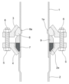
도 1에 도시된 바와 같이 제1관(1)과 제2관(2)을 서로 연결하는 경우, 상기 제1관(1)을 제2관(2) 내부에 삽입하여 중첩시키고, 상기 제1관(1) 측에는 제1가압플랜지(3)를 장착하며, 상기 제2관(2) 측에는 제2가압플랜지(4)를 장착한 후 상기 제1가압플랜지(3)와 제2가압플랜지(4)를 볼트(5) 및 너트(6)로 체결하여 연결할 수 있다.As shown in FIG. 1, when the
이때, 상기 제1관(1)이 제2관(2)에 삽입될 수 있도록 상기 제2관(2)의 단부는 내경이 확장된 확장부()가 형성되게 하고, 상기 제1관(1)과 확장부() 사이에 형성되는 공간에 링 형상의 패킹(7)을 삽입한다.At this time, the end of the second tube (2) is formed with an expansion part () having an expanded inner diameter so that the first tube (1) can be inserted into the second tube (2), and the first tube (1) A ring-
그리고 상기 제1관(1)과 제1가압플랜지(3) 사이에 링 형상의 지지링(8)을 삽입하는데, 지지링(8)은 SUS 재질로 이루어질 수 있고, 내주면에는 상기 제1관(1)의 외주면의 원주방향을 따라 오목하게 형성된 환형지지홈(1a)에 삽입되어 걸릴 수 있도록 볼록한 리브(8a)가 형성된다.In addition, a ring-
또 상기 지지링(8)과 패킹 사이에 MC나일론 재질로 이루어진 가압링(9)이 구비된다.In addition, a
따라서, 상기 제1가압플랜지(3)와 제2가압플랜지(4)를 조이면, 상기 패킹(7)이 상기 지지링(8) 측으로 이동하면서 상기 가압링(9)이 상기 패킹(7)의 일측을 가압한다.Therefore, when the first pressure flange 3 and the
가압된 상기 패킹(7)은 압착되면서 타측이 팽창하여 상기 제1관(1)과 확관부(2a)에 각각 밀착되어 실링이 이루어진다.The
그런데 도 2에 도시된 종래 패킹은 단면이 대략 사각형 또는 사다리꼴을 이루기 때문에 기밀성이 취약한 단점이 있다. However, since the conventional packing shown in FIG. 2 has a substantially rectangular or trapezoidal cross section, airtightness is weak.
이를 해결하기 위해 종래 다양한 형상의 패킹이 제안되었으나, 기밀성을 높이기 위한 최적의 형상이 여전히 요구되고 있다. In order to solve this problem, packings of various shapes have been conventionally proposed, but an optimal shape for increasing airtightness is still required.
이에 본 발명은 상술한 문제점을 해결하기 위한 것으로서, 본 발명의 목적은 기밀성을 향상시키기 위해 최적의 형상을 가진 조인트 패킹을 제공하는 것이다.Accordingly, the present invention is to solve the above problems, and an object of the present invention is to provide a joint packing having an optimal shape to improve airtightness.
상기한 목적 달성을 위한 본 발명에 따른 조인트 패킹은, 제1관과 제2관을 상호 연결하기 위해 상기 제2관의 단부에 형성된 확관부와 상기 제1관 사이에 삽입되어 실링을 수행할 수 있는 패킹에 있어서, 상기 패킹은, 링 형상으로 이루어지고 단면이 사각형을 이루는 본체; 상기 본체의 상부면에 'V' 형상으로 형성되어 상기 본체가 측방향으로 팽창하도록 하는 노치; 상기 본체의 하부면으로부터 연장 형성되고 상기 제1관이 삽입되는 방향으로 경사지게 형성되어 상기 제1관에 밀착되는 제1기밀돌기; 상기 제1기밀돌기의 일측에 이격되어 상기 본체의 하부면으로부터 연장 형성되고, 상기 제1기밀돌기와 동일한 방향으로 경사지게 형성되어 상기 확관부에 밀착되는 제2기밀돌기;를 포함하여 이루어지되, 상기 제1기밀돌기와 제2기밀돌기 사이에는 'U'형상의 밀착유도홈이 형성될 수 있다.The joint packing according to the present invention for achieving the above object can be inserted between the expansion part formed at the end of the second pipe and the first pipe to interconnect the first pipe and the second pipe to perform sealing. In the packing, the packing is made of a ring shape, the cross section of which forms a rectangular body; a notch formed in a 'V' shape on the upper surface of the main body to expand the main body in a lateral direction; a first confidential protrusion extending from the lower surface of the main body and inclined in a direction into which the first tube is inserted to be in close contact with the first tube; A second confidential projection formed to extend from the lower surface of the main body, spaced apart from one side of the first confidential projection, and inclined in the same direction as the first confidential projection to be in close contact with the expansion tube; A 'U'-shaped close contact guide groove may be formed between the first confidential projection and the second confidential projection.
여기서, 상기 노치의 내각은 45 ~ 60°이고, 상기 제1기밀돌기와 제2기밀돌기가 이루는 각은 20 ~ 25°인 것이 바람직하다.Here, it is preferable that the interior angle of the notch is 45 to 60°, and the angle formed by the first and second confidential projections is 20 to 25°.
그리고 상기 본체의 내주면과 외주면에는 볼록한 철부와 오목한 요부가 반복되어 파형을 이루는 파형돌기가 형성된 구조를 이룰 수 있다. In addition, a convex convex portion and a concave concave portion may be repeated on the inner circumferential surface and the outer circumferential surface of the main body to form a structure in which corrugated protrusions forming a waveform are formed.
또 상기 제2기밀돌기의 표면에도 상기 파형돌기가 형성된다.Also, the corrugated protrusion is formed on the surface of the second hermetic protrusion.
또한, 상기 본체와 제2기밀돌기가 만나는 지점에 둥근 라운딩부가 형성된다. In addition, a rounded portion is formed at a point where the main body and the second hermetic protrusion meet.
상기와 같은 구성으로 이루어진 본 발명은 아래와 같은 효과가 있다.The present invention composed of the above configuration has the following effects.
첫째, 패킹 본체에 노치가 형성되어 있으므로 가압시 노치가 벌어지면서 본체가 측방향을 용이하게 팽창될 수 있기 때문에 기밀성이 향상된다.First, since the notch is formed in the packing body, airtightness is improved because the body can be easily expanded in the lateral direction while the notch is widened when pressurized.
둘째, 제1기밀돌기와 제2기밀돌기 사이에 밀착유도홈이 형성되어 제1기밀돌기와 제2기밀돌기가 탄성적으로 벌어지게 유도하기 때문에 기밀성이 향상된다.Second, confidentiality is improved because an adhesion guide groove is formed between the first and second confidential projections to induce the first and second confidential projections to spread elastically.
셋째, 파형돌기가 오링과 같은 기능을 하기 때문에 기밀성이 향상된다. Third, confidentiality is improved because the corrugated protrusion functions like an O-ring.
도 1은 종래 배관 연결용 패킹을 사용한 배관연결 예시도
도 2는 종래 배관 연결용 패킹을 나타내는 사시도
도 3은 본 발명의 일 실시 예를 따른 조인트 패킹을 나타내는 사시도 및 단면도
도 4는 본 발명의 사용상태도1 is an exemplary view of pipe connection using a conventional packing for pipe connection
Figure 2 is a perspective view showing a packing for conventional pipe connection
Figure 3 is a perspective view and cross-sectional view showing a joint packing according to an embodiment of the present invention
4 is a use state diagram of the present invention
이하, 본 발명에 따른 일 실시 예를 첨부한 도면을 참조하여 보다 상세하게 설명하기로 한다.Hereinafter, an embodiment according to the present invention will be described in more detail with reference to the accompanying drawings.
참고로, 도면을 참조한 설명은 본 발명을 더 쉽게 이해하기 위한 것으로, 본 발명의 범주가 그것에 의해 한정되는 것은 아니다. 그리고 본 발명을 설명함에 있어, 관련된 공지기술에 대한 구체적인 설명이 본 발명의 요지를 불필요하게 흐릴 수 있다고 판단될 경우, 상세한 설명은 생략하기로 한다.For reference, the description with reference to the drawings is for easier understanding of the present invention, and the scope of the present invention is not limited thereto. And, in describing the present invention, if it is determined that a detailed description of related known technologies may unnecessarily obscure the subject matter of the present invention, the detailed description will be omitted.
도 3은 본 발명의 일 실시 예를 따른 조인트 패킹을 나타내는 사시도이다.3 is a perspective view showing a joint packing according to an embodiment of the present invention.
본 발명의 일 실시 예를 따른 조인트 패킹은 도시된 바를 참조하면, 본체(100), 노치(200), 제1기밀돌기(300), 제2기밀돌기(400), 밀착유도홈(500)을 포함하여 구성될 수 있고 파형돌기(600)가 더 포함될 수 있다.Referring to the joint packing according to an embodiment of the present invention, the
먼저, 상기 본체(100)에 대해 설명한다.First, the
상기 본체(100)는 전체적으로 원형의 링 형상을 이룬다. 그리고 종단면의 형상은 대략 사각형을 이룰 수 있다.The
또 상기 본체(100)는 고무와 같은 탄성재질로 이루어지므로 일측에서 가압하면 형상이 변형되고 힘이 제거되면 다시 원상태로 복원될 수 있다. 따라서, 상기 본체(100)의 상부와 하부에서 힘을 가하면 양측면으로 팽창하면서 변형되어 납작해졌다가 가압력이 제거되면 원래의 형상으로 복원될 수 있다.In addition, since the
참고로 상기 본체(100)의 내경은 삽입되는 제1관(1)의 외경과 동일하게 형성되어 상기 본체(100)의 내부에 상기 제1관(1)의 삽입이 용이하다.For reference, the inner diameter of the
다음으로 상기 노치(200)에 대해 설명한다.Next, the
상기 노치(200)는 상기 본체(100)의 상부면에 오목하게 형성되는 홈이다.The
상기 노치(200)의 단면 형상은 다양하게 형성될 수 있으나, 바람직하게는 'V' 형상일 수 있다.The cross-sectional shape of the
이것은 상기 본체(100)의 상부면이 가압될 때 양측으로 팽창이 용이하도록 하기 위함이다.This is to facilitate expansion to both sides when the upper surface of the
다시 말해서, 가압력이 상기 노치(200)의 양측으로 집중되면서 상기 노치를 중심으로 양측으로 미는 방향으로 가해지므로, 상기 본체(100)의 상부가 양측으로 벌어지게 되고 이로 인해 팽창하게 되어 제1관(1)과 확관부(2a)에 확실히 밀착될 수 있다. In other words, since the pressing force is concentrated on both sides of the
여기서, 상기 노치(200)의 벌어진 내각(N)은 45 ~ 60°인 것이 바람직하다.Here, the widened inner angle N of the
만일, 상기 노치(200)의 내각이 45°보다 작아지면, 상기 노치(200)가 없는 상태에 가까워지므로 상기 본체(100)가 가압될 때 팽창이 잘 발생하지 못한다.If the interior angle of the
반면, 상기 노치(200)의 내각이 60°보다 커지면, 상기 본체(100)가 이미 벌어진 상태와 같이 되기 때문에 실제 가압될 때 양측으로 팽창되는 정도가 약해진다. On the other hand, if the inner angle of the
바람직한 것은 상기 노치(200)의 내각은 50°내외가 적절할 것이다. Preferably, the inside angle of the
다음으로 상기 제1기밀돌기(300)에 대해 설명한다.Next, the first
상기 제1기밀돌기(300)는 상기 본체(100)의 하부면으로부터 하측으로 연장 돌출형성되고, 상기 본체(100)의 두께보다 작은 두께를 가지도록 얇게 형성된다.The first
그리고 상기 제1기밀돌기(300)는 상기 제1관(1)의 외주면 측으로 내향 경사지게 형성되고 단부로 갈수록 두께가 감소하여 끝이 뾰족한 첨부(310)가 형성된 테이퍼진 구조를 가지므로 상기 제1관(1)에 밀착이 용이하다.In addition, the first
더불어, 상기 제1기밀돌기(300)의 첨부(310)가 이루는 내경은 상기 제1관(1)의 내경보다 작게 형성되어 상기 제1관(1)에 밀착력이 향상된다. In addition, the inner diameter formed by the
또 상기 제1기밀돌기(300)는 상기 본체를 따라 연속적으로 형성되어 원형을 이루고 상기 본체(100)와 일체로 성형될 수 있다.In addition, the first
다음으로 상기 제2기밀돌기(400)에 대해 설명한다.Next, the second
상기 제2기밀돌기(400)는 상기 제1기밀돌기와 유사한 형상을 가질 수 있다.The second
즉, 상기 본체(100)의 하부면으로부터 연장 돌출형성되고, 상기 제1기밀돌기(300)의 일측에 인접하여 이격되어 형성된다.That is, it extends and protrudes from the lower surface of the
그리고 상기 제2기밀돌기(400)도 상기 제1기밀돌기(300)와 동일한 방향으로 내향 경사지게 형성된다. Also, the second
또 상기 제2기밀돌기(400)의 두께는 상기 본체(100)의 두께보다 작게 형성되고, 단부로 갈수록 두께가 감소하여 끝이 뾰족한 첨부(410)가 형성된 테이퍼진 구조를 가질 수 있다.In addition, the thickness of the
따라서, 상기 제2기밀돌기(400)는 제2관(2)의 테이퍼진 확관부(2a)의 내면에 밀착될 수 있다.Therefore, the second
여기서, 상기 제1기밀돌기(300)와 제2기밀돌기(400) 사이는 일정 간격을 두고 이격되어 있고 만나는 지점 내부에 밀착유도홈(500)이 형성된다. Here, the first
상기 밀착유도홈(500)은 상기 제1기밀돌기(300)와 제2기밀돌기(400)가 가압될 때 서로 쉽게 포개어지는 것을 방지하고, 오히려 벌어지도록 유도한다.The close
즉, 상기 밀착유도홈(500)이 형성됨으로써 상기 제1기밀돌기(300)와 제2기밀돌기(400)의 첨부는 서로 포개어지면서 면밀착되지만, 상기 밀착유도홈(500)의 주변은 서로 밀착되지 않도록 저항을 받아 공간이 형성되며, 이로 인해 상기 제1기밀돌기(300)와 제2기밀돌기(400)가 벌어져 복원되게 하는 탄성을 제공한다.That is, by forming the close
따라서, 상기 제1기밀돌기(300)는 상기 제1관(1)에 더욱 밀착되도록 탄성력을 받고, 상기 제2기밀돌기(400)는 상기 제2관(2)의 확관부(2a)에 밀착되도록 탄성력을 받을 수 있다.Therefore, the first
참고로 상기 밀착유도홈(500)이 단면이 'V' '┗┛'와 같은 형상을 이룰 수 있으나, 'U'형상을 이루는 것이 바람직하다. 왜냐하면, 단면이 둥글게 형성되어야 접히지 않고, 벌어지도록 하는 탄성력이 가장 크기 때문이다. For reference, the cross-section of the
한편, 상기 제1기밀돌기(300)와 제2기밀돌기(400)가 이루는 각(S)이 20 ~ 25°인 것이 좋다.On the other hand, it is preferable that the angle (S) formed by the first
구체적으로 상기 제1기밀돌기(300)의 외면과 상기 제2기밀돌기의 내면이 이루는 각이 20 ~ 25°이고, 23°가 가장 바람직할 것이다.Specifically, the angle between the outer surface of the first
만일, 20°보다 작으면, 상기 제1기밀돌기(300)와 제2기밀돌기(400)가 벌어지게 하려는 탄성력이 급격히 낮아지므로 밀착력이 감소되어 기밀성이 떨어진다. If the angle is smaller than 20°, the elastic force for opening the first and second
반면, 25°보다 커지면, 벌어지게 하려는 탄성력이 너무 강해져서, 조립성이 떨어지고, 상기 제2기밀돌기(400)가 상기 확관부(2a)에 밀착되는 면적이 줄어들어 이 역시 기밀성이 저하된다.On the other hand, when the angle is greater than 25°, the elastic force to widen becomes too strong, and assembling properties deteriorate, and the area where the second
다음으로 본 발명의 다른 실시 예를 설명한다.Next, another embodiment of the present invention will be described.
본 발명의 다른 실시 예는 상기 본체(100)의 내주면과 외주면에 파형돌기(600)가 형성된 구조를 가질 수 있다.Another embodiment of the present invention may have a structure in which the
상기 파형돌기(600)는 볼록한 철부(산)와 오목한 요부(골)가 반복되어 파형의 단면을 이룬다. 그리고 상기 파형돌기(600)는 하나 이상 형성될 수 있다 The
또 상기 파형돌기(600)는 상기 제2기밀돌기(400)의 외면에도 형성되는 것이 바람직하다.In addition, it is preferable that the
이러한 상기 파형돌기(600)는 둥글게 형성되어 마치 오링과 같이 작용할 수 있다.The
즉, 상기 본체(100)가 가압력에 의해 압축되면, 상기 파형돌기(600)들이 옆으로 팽창하면서 상기 제1관(1)의 외주면과 상기 확관부(2a)의 내주면에 찌그러지면서 강하게 밀착될 수 있다.That is, when the
또한, 상기 본체(100)와 제2기밀돌기(400)가 만나는 지점에 둥근 라운딩부(110)가 형성되어 상기 본체(100)의 압축시 상기 확관부(2a)를 따라 밀려가면서 변형되어 상기 확관부(2a)의 모서리에 더욱 밀착될 수 있다.In addition, a
이하에서 도 4를 참조하여 본 발명의 사용상태를 설명한다. 도 4는 본 발명의 사용상태도를 나타낸다.Hereinafter, the use state of the present invention will be described with reference to FIG. 4 . 4 shows a use state diagram of the present invention.
본 발명에 따른 조인트 패킹은 도시된 바와 같이, 연결하고자 하는 두 관, 다시 말해서, 제1관(1)과 제2관(2) 사이에 개재되어 두 배관을 흐르는 유체의 누설을 기밀하기 위한 구성이다. As shown, the joint packing according to the present invention is interposed between two pipes to be connected, that is, the first pipe (1) and the second pipe (2) to seal the leakage of the fluid flowing through the two pipes. am.
상기 제1관(1)과 제2관(2)을 서로 연결하기 위해, 상기 제1관(1)에 상기 제1가압플랜지(3)를 관통, 장착하고, 이어서 상기 환형지지홈(1a)에 상기 지지링(8)을 끼우며, 더불어 순서대로 상기 가압링(9)과 패킹(7)도 끼운다.In order to connect the first pipe (1) and the second pipe (2) to each other, the first pressure flange (3) is penetrated and mounted in the first pipe (1), and then the annular support groove (1a) The
그리고 상기 제2관(2)에도 상기 제2가압플랜지(4)를 관통, 장착하고, 상기 제1관(1)의 단부를 상기 제2관(2)에 삽입하여 연결하되, 상기 패킹(7)이 상기 확관부(2a)에 삽입되게 한다. In addition, the
이 상태에서 상기 제1가압플랜지(3)와 제2가압플랜지(4)를 볼트(5)와 너트(6)로 체결하여 조여주면, 상기 제1가압플랜지(3)는 상기 지지링(8)에 의 해지지되므로 상기 제2가압플랜지(4)가 상기 확관부(2a)를 가압하면서 밀어올리면 상기 패킹(7)이 상기 가압링(9)에 의해 압축되면서 도 4에 도시된 바와 같이 변형이 발생한다. In this state, if the first pressure flange (3) and the second pressure flange (4) are tightened by fastening them with bolts (5) and nuts (6), the first pressure flange (3) is connected to the support ring (8). Since the
즉, 상기 본체(100)가 압축되므로 상기 노치(200)가 벌어지면서 상기 본체(100)의 내주면과 외주면이 각각 팽창하게 된다. That is, since the
이로 인해 상기 파형돌기(600)는 각각 상기 제1관(1)의 외주면과 상기 확관부(2a)의 내주면에 찌그러지면서 강하게 밀착되어 실링을 수행한다.Due to this, the
그리고 상기 제1기밀돌기(300)는 상기 제1관(1)의 외주면에 면밀착되고, 상기 제2기밀돌기(400)는 상기 밀착유도홈(500)의 저항과 탄성을 극복하고 상기 제1기밀돌기(300)와 포개어진다. 이때, 상기 밀착유도홈(500)은 도시된 바와 같이 사라지는 것이 아니라 물방울과 같은 형상의 공간을 형성한다.In addition, the first
따라서, 상술한 바와 같이 상기 밀착유도홈(500)의 벌어지려는 탄성으로 인해 상기 제1기밀돌기(300)와 제2기밀돌기(400)는 벌어지는 방향으로 탄성력을 받아 각각 상기 제1관(1)의 외주면과 확관부(2a)의 내주면에 더욱 강하게 밀착될 수 있다. 즉, 기밀성이 크게 향상된다.Therefore, as described above, due to the elasticity of the close
이상에서 도면을 참조하여 본 발명의 대표적인 실시 예를 설명하였지만, 본 발명이 속한 분야에서 통상의 지식을 가진 자라면 상기 내용을 바탕으로 본 발명의 범주 내에서 다양한 응용 및 변형을 행하는 것이 가능할 것이다. 그러므로 본 발명의 권리범위는 설명된 실시 예에 국한되어 정해져서는 안되며, 후술하는 특허청구범위뿐만 아니라 이 특허청구범위와 균등한 것들에 의해 정해져야 한다.Representative embodiments of the present invention have been described above with reference to the drawings, but those skilled in the art will be able to make various applications and modifications within the scope of the present invention based on the above information. Therefore, the scope of the present invention should not be limited to the described embodiments and should not be defined, but should be defined by not only the claims to be described later, but also those equivalent to these claims.
1 : 제1관
1a : 환형홈
2 : 제2관
2a : 확관부
3 : 제1가압플랜지
4 : 제2가압플랜지
5 : 볼트
6 : 너트
7 : 패킹
8 : 지지링
8a : 리브
9 : 가압링
100 : 본체
110 : 라운딩부
200 : 노치
300 : 제1기밀돌기
310 : 첨부
400 : 제2기밀돌기
410 : 첨부
500 : 밀착유도홈
600 : 파형돌기1:
2:
3: first pressure flange 4: second pressure flange
5: bolt 6: nut
7: packing 8: support ring
8a: rib 9: pressure ring
100: main body 110: rounding part
200: notch
300: first secret protrusion 310: attached
400: second secret protrusion 410: attached
500: adhesion induction groove
600: wave protrusion
Claims (6)
상기 패킹은,
링 형상으로 이루어지고 단면이 사각형을 이루는 본체;
상기 본체의 상부면에 'V' 형상으로 형성되어 상기 본체가 측방향으로 팽창하도록 하는 노치;
상기 본체의 하부면으로부터 연장 형성되고 상기 제1관이 삽입되는 방향으로 경사지게 형성되어 상기 제1관에 밀착되는 제1기밀돌기;
상기 제1기밀돌기의 일측에 이격되어 상기 본체의 하부면으로부터 연장 형성되고, 상기 제1기밀돌기와 동일한 방향으로 경사지게 형성되어 상기 확관부에 밀착되는 제2기밀돌기;를 포함하여 이루어지되,
상기 제1기밀돌기와 제2기밀돌기 사이에는 'U'형상의 밀착유도홈이 형성되는 것을 특징으로 하는 조인트 패킹.In the packing that can be inserted between the first tube and the expanded tube formed at the end of the second tube to interconnect the first tube and the second tube to perform sealing,
The packing is
A body made in a ring shape and having a rectangular cross section;
a notch formed in a 'V' shape on the upper surface of the main body to expand the main body in a lateral direction;
a first confidential protrusion extending from the lower surface of the main body and inclined in a direction into which the first tube is inserted to be in close contact with the first tube;
A second secret protrusion spaced apart from one side of the first secret protrusion, extending from the lower surface of the main body, and inclined in the same direction as the first secret protrusion to be in close contact with the expansion tube;
Joint packing, characterized in that a 'U'-shaped close contact guide groove is formed between the first and second confidential projections.
상기 노치의 내각은 45 ~ 60°인 것을 특징으로 하는 조인트 패킹.According to claim 1,
Joint packing, characterized in that the interior angle of the notch is 45 ~ 60 °.
상기 제1기밀돌기와 제2기밀돌기가 이루는 각은 20 ~ 25°인 것을 특징으로 하는 조인트 패킹.According to claim 1,
Joint packing, characterized in that the angle formed by the first confidential projection and the second confidential projection is 20 ~ 25 °.
상기 본체의 내주면과 외주면에는 볼록한 철부와 오목한 요부가 반복되어 파형을 이루는 파형돌기가 형성된 구조를 이루는 것을 특징으로 하는 조인트 패킹.According to claim 1,
Joint packing, characterized in that the convex convex portion and the concave concave portion are repeated on the inner and outer circumferential surfaces of the main body to form a structure in which corrugated protrusions forming a waveform are formed.
상기 제2기밀돌기의 표면에도 상기 파형돌기가 형성되는 것을 특징으로 하는 조인트 패킹.According to claim 4,
Joint packing, characterized in that the corrugated protrusion is formed on the surface of the second hermetic protrusion.
상기 본체와 제2기밀돌기가 만나는 지점에 둥근 라운딩부가 형성되는 것을 특징으로 하는 조인트 패킹.According to claim 1,
Joint packing, characterized in that a round rounding portion is formed at the point where the main body and the second hermetic protrusion meet.
Priority Applications (1)
| Application Number | Priority Date | Filing Date | Title |
|---|---|---|---|
| KR1020210177026A KR102669657B1 (en) | 2021-12-10 | 2021-12-10 | Joint packing |
Applications Claiming Priority (1)
| Application Number | Priority Date | Filing Date | Title |
|---|---|---|---|
| KR1020210177026A KR102669657B1 (en) | 2021-12-10 | 2021-12-10 | Joint packing |
Publications (2)
| Publication Number | Publication Date |
|---|---|
| KR20230088134A true KR20230088134A (en) | 2023-06-19 |
| KR102669657B1 KR102669657B1 (en) | 2024-05-27 |
Family
ID=86988325
Family Applications (1)
| Application Number | Title | Priority Date | Filing Date |
|---|---|---|---|
| KR1020210177026A Active KR102669657B1 (en) | 2021-12-10 | 2021-12-10 | Joint packing |
Country Status (1)
| Country | Link |
|---|---|
| KR (1) | KR102669657B1 (en) |
Cited By (1)
| Publication number | Priority date | Publication date | Assignee | Title |
|---|---|---|---|---|
| KR102804670B1 (en) * | 2024-04-04 | 2025-05-08 | 주식회사 한양하이텍 | Pipe assembly with improved watertightness |
Citations (7)
| Publication number | Priority date | Publication date | Assignee | Title |
|---|---|---|---|---|
| JPS5737181U (en) * | 1980-08-12 | 1982-02-26 | ||
| JPH0564592U (en) * | 1991-12-10 | 1993-08-27 | 株式会社エム・エス・ジャパン | Pipe joint structure |
| KR200336910Y1 (en) | 2003-09-09 | 2004-01-03 | 전금진 | Packing for connecting plastic pipes having folded surface |
| KR200377322Y1 (en) | 2004-12-08 | 2005-03-08 | 주식회사 선진프라스틱 | packing for Piping connection |
| KR200419731Y1 (en) | 2006-02-14 | 2006-06-23 | 사회복지법인 안동 시온재단 | Rubber packing for pipe connection |
| KR100645916B1 (en) * | 2006-03-27 | 2006-11-23 | 건설화성 주식회사 | Synthetic Resin Pipe Connection Assembly for Head Integral Water Pipe |
| KR20170044300A (en) * | 2015-10-15 | 2017-04-25 | 현대주철산업 주식회사 | Device for connecting water pipes of one-touch type |
-
2021
- 2021-12-10 KR KR1020210177026A patent/KR102669657B1/en active Active
Patent Citations (7)
| Publication number | Priority date | Publication date | Assignee | Title |
|---|---|---|---|---|
| JPS5737181U (en) * | 1980-08-12 | 1982-02-26 | ||
| JPH0564592U (en) * | 1991-12-10 | 1993-08-27 | 株式会社エム・エス・ジャパン | Pipe joint structure |
| KR200336910Y1 (en) | 2003-09-09 | 2004-01-03 | 전금진 | Packing for connecting plastic pipes having folded surface |
| KR200377322Y1 (en) | 2004-12-08 | 2005-03-08 | 주식회사 선진프라스틱 | packing for Piping connection |
| KR200419731Y1 (en) | 2006-02-14 | 2006-06-23 | 사회복지법인 안동 시온재단 | Rubber packing for pipe connection |
| KR100645916B1 (en) * | 2006-03-27 | 2006-11-23 | 건설화성 주식회사 | Synthetic Resin Pipe Connection Assembly for Head Integral Water Pipe |
| KR20170044300A (en) * | 2015-10-15 | 2017-04-25 | 현대주철산업 주식회사 | Device for connecting water pipes of one-touch type |
Cited By (1)
| Publication number | Priority date | Publication date | Assignee | Title |
|---|---|---|---|---|
| KR102804670B1 (en) * | 2024-04-04 | 2025-05-08 | 주식회사 한양하이텍 | Pipe assembly with improved watertightness |
Also Published As
| Publication number | Publication date |
|---|---|
| KR102669657B1 (en) | 2024-05-27 |
Similar Documents
| Publication | Publication Date | Title |
|---|---|---|
| US6550775B2 (en) | Annular gasket | |
| CN1813150B (en) | Gaskets for pipe joints and pipe joints including gaskets | |
| US4298206A (en) | Flexible packing for sealing pipeline joints | |
| US6336640B1 (en) | Gasket | |
| KR100981919B1 (en) | All-in-one corrugated steel pipe | |
| KR102669657B1 (en) | Joint packing | |
| CA2882908C (en) | Corrugated pipe gasket | |
| US4614371A (en) | Ring | |
| KR100596742B1 (en) | Pipe connection structure | |
| KR20190073237A (en) | Packing for connecting pipe | |
| JPH0716151Y2 (en) | Pipe joint structure | |
| KR200252276Y1 (en) | Packing for pipe connecter | |
| KR101712315B1 (en) | Pipe coupling device | |
| CN111480027B (en) | Corrugated pipe connecting device and connecting method thereof | |
| KR200493485Y1 (en) | Rubber ring for piping | |
| KR100962446B1 (en) | Piping Coupling | |
| KR200413764Y1 (en) | Water pipe coupling device | |
| JPH0514071Y2 (en) | ||
| KR100334584B1 (en) | Construction to connect of tube | |
| JPH074958U (en) | Annular packing | |
| JPH04244692A (en) | Mating flange for flexible tube fitting | |
| KR100213407B1 (en) | Pipe fittings | |
| KR200467368Y1 (en) | Pipe Ends with Extension Rings for Pipe Ends | |
| KR200346747Y1 (en) | pipe joining structure | |
| KR20130075098A (en) | Structure of rubber-seal for mechanical fitting and it's applied mechanical fitting |
Legal Events
| Date | Code | Title | Description |
|---|---|---|---|
| PA0109 | Patent application |
St.27 status event code: A-0-1-A10-A12-nap-PA0109 |
|
| PA0201 | Request for examination |
St.27 status event code: A-1-2-D10-D11-exm-PA0201 |
|
| R18-X000 | Changes to party contact information recorded |
St.27 status event code: A-3-3-R10-R18-oth-X000 |
|
| PG1501 | Laying open of application |
St.27 status event code: A-1-1-Q10-Q12-nap-PG1501 |
|
| E902 | Notification of reason for refusal | ||
| PE0902 | Notice of grounds for rejection |
St.27 status event code: A-1-2-D10-D21-exm-PE0902 |
|
| E13-X000 | Pre-grant limitation requested |
St.27 status event code: A-2-3-E10-E13-lim-X000 |
|
| P11-X000 | Amendment of application requested |
St.27 status event code: A-2-2-P10-P11-nap-X000 |
|
| P13-X000 | Application amended |
St.27 status event code: A-2-2-P10-P13-nap-X000 |
|
| E701 | Decision to grant or registration of patent right | ||
| PE0701 | Decision of registration |
St.27 status event code: A-1-2-D10-D22-exm-PE0701 |
|
| GRNT | Written decision to grant | ||
| PR0701 | Registration of establishment |
St.27 status event code: A-2-4-F10-F11-exm-PR0701 |
|
| PR1002 | Payment of registration fee |
St.27 status event code: A-2-2-U10-U11-oth-PR1002 Fee payment year number: 1 |
|
| PG1601 | Publication of registration |
St.27 status event code: A-4-4-Q10-Q13-nap-PG1601 |
|
| P14 | Amendment of ip right document requested |
Free format text: ST27 STATUS EVENT CODE: A-5-5-P10-P14-NAP-X000 (AS PROVIDED BY THE NATIONAL OFFICE) |
|
| P14-X000 | Amendment of ip right document requested |
St.27 status event code: A-5-5-P10-P14-nap-X000 |
|
| PN2301 | Change of applicant |
St.27 status event code: A-5-5-R10-R11-asn-PN2301 |
|
| R11 | Change to the name of applicant or owner or transfer of ownership requested |
Free format text: ST27 STATUS EVENT CODE: A-5-5-R10-R11-ASN-PN2301 (AS PROVIDED BY THE NATIONAL OFFICE) |
|
| P16 | Ip right document amended |
Free format text: ST27 STATUS EVENT CODE: A-5-5-P10-P16-NAP-X000 (AS PROVIDED BY THE NATIONAL OFFICE) |
|
| P16-X000 | Ip right document amended |
St.27 status event code: A-5-5-P10-P16-nap-X000 |
|
| PN2301 | Change of applicant |
St.27 status event code: A-5-5-R10-R14-asn-PN2301 |
|
| R14 | Transfer of ownership recorded |
Free format text: ST27 STATUS EVENT CODE: A-5-5-R10-R14-ASN-PN2301 (AS PROVIDED BY THE NATIONAL OFFICE) |