KR20230077035A - Liquid hydrogen storage tank to which 3D printing-epoxy composite material is applied and its manufacturing method - Google Patents
Liquid hydrogen storage tank to which 3D printing-epoxy composite material is applied and its manufacturing method Download PDFInfo
- Publication number
- KR20230077035A KR20230077035A KR1020210163782A KR20210163782A KR20230077035A KR 20230077035 A KR20230077035 A KR 20230077035A KR 1020210163782 A KR1020210163782 A KR 1020210163782A KR 20210163782 A KR20210163782 A KR 20210163782A KR 20230077035 A KR20230077035 A KR 20230077035A
- Authority
- KR
- South Korea
- Prior art keywords
- tank
- liquid hydrogen
- epoxy
- printing
- storage tank
- Prior art date
- Legal status (The legal status is an assumption and is not a legal conclusion. Google has not performed a legal analysis and makes no representation as to the accuracy of the status listed.)
- Granted
Links
Images


Classifications
-
- F—MECHANICAL ENGINEERING; LIGHTING; HEATING; WEAPONS; BLASTING
- F17—STORING OR DISTRIBUTING GASES OR LIQUIDS
- F17C—VESSELS FOR CONTAINING OR STORING COMPRESSED, LIQUEFIED OR SOLIDIFIED GASES; FIXED-CAPACITY GAS-HOLDERS; FILLING VESSELS WITH, OR DISCHARGING FROM VESSELS, COMPRESSED, LIQUEFIED, OR SOLIDIFIED GASES
- F17C3/00—Vessels not under pressure
- F17C3/02—Vessels not under pressure with provision for thermal insulation
- F17C3/08—Vessels not under pressure with provision for thermal insulation by vacuum spaces, e.g. Dewar flask
- F17C3/085—Cryostats
-
- B—PERFORMING OPERATIONS; TRANSPORTING
- B33—ADDITIVE MANUFACTURING TECHNOLOGY
- B33Y—ADDITIVE MANUFACTURING, i.e. MANUFACTURING OF THREE-DIMENSIONAL [3D] OBJECTS BY ADDITIVE DEPOSITION, ADDITIVE AGGLOMERATION OR ADDITIVE LAYERING, e.g. BY 3D PRINTING, STEREOLITHOGRAPHY OR SELECTIVE LASER SINTERING
- B33Y80/00—Products made by additive manufacturing
-
- B—PERFORMING OPERATIONS; TRANSPORTING
- B64—AIRCRAFT; AVIATION; COSMONAUTICS
- B64D—EQUIPMENT FOR FITTING IN OR TO AIRCRAFT; FLIGHT SUITS; PARACHUTES; ARRANGEMENT OR MOUNTING OF POWER PLANTS OR PROPULSION TRANSMISSIONS IN AIRCRAFT
- B64D37/00—Arrangements in connection with fuel supply for power plant
- B64D37/02—Tanks
-
- F—MECHANICAL ENGINEERING; LIGHTING; HEATING; WEAPONS; BLASTING
- F17—STORING OR DISTRIBUTING GASES OR LIQUIDS
- F17C—VESSELS FOR CONTAINING OR STORING COMPRESSED, LIQUEFIED OR SOLIDIFIED GASES; FIXED-CAPACITY GAS-HOLDERS; FILLING VESSELS WITH, OR DISCHARGING FROM VESSELS, COMPRESSED, LIQUEFIED, OR SOLIDIFIED GASES
- F17C13/00—Details of vessels or of the filling or discharging of vessels
- F17C13/001—Thermal insulation specially adapted for cryogenic vessels
-
- F—MECHANICAL ENGINEERING; LIGHTING; HEATING; WEAPONS; BLASTING
- F17—STORING OR DISTRIBUTING GASES OR LIQUIDS
- F17C—VESSELS FOR CONTAINING OR STORING COMPRESSED, LIQUEFIED OR SOLIDIFIED GASES; FIXED-CAPACITY GAS-HOLDERS; FILLING VESSELS WITH, OR DISCHARGING FROM VESSELS, COMPRESSED, LIQUEFIED, OR SOLIDIFIED GASES
- F17C3/00—Vessels not under pressure
- F17C3/02—Vessels not under pressure with provision for thermal insulation
- F17C3/04—Vessels not under pressure with provision for thermal insulation by insulating layers
-
- B—PERFORMING OPERATIONS; TRANSPORTING
- B33—ADDITIVE MANUFACTURING TECHNOLOGY
- B33Y—ADDITIVE MANUFACTURING, i.e. MANUFACTURING OF THREE-DIMENSIONAL [3D] OBJECTS BY ADDITIVE DEPOSITION, ADDITIVE AGGLOMERATION OR ADDITIVE LAYERING, e.g. BY 3D PRINTING, STEREOLITHOGRAPHY OR SELECTIVE LASER SINTERING
- B33Y40/00—Auxiliary operations or equipment, e.g. for material handling
-
- F—MECHANICAL ENGINEERING; LIGHTING; HEATING; WEAPONS; BLASTING
- F17—STORING OR DISTRIBUTING GASES OR LIQUIDS
- F17C—VESSELS FOR CONTAINING OR STORING COMPRESSED, LIQUEFIED OR SOLIDIFIED GASES; FIXED-CAPACITY GAS-HOLDERS; FILLING VESSELS WITH, OR DISCHARGING FROM VESSELS, COMPRESSED, LIQUEFIED, OR SOLIDIFIED GASES
- F17C2201/00—Vessel construction, in particular geometry, arrangement or size
- F17C2201/01—Shape
- F17C2201/0104—Shape cylindrical
- F17C2201/0109—Shape cylindrical with exteriorly curved end-piece
-
- F—MECHANICAL ENGINEERING; LIGHTING; HEATING; WEAPONS; BLASTING
- F17—STORING OR DISTRIBUTING GASES OR LIQUIDS
- F17C—VESSELS FOR CONTAINING OR STORING COMPRESSED, LIQUEFIED OR SOLIDIFIED GASES; FIXED-CAPACITY GAS-HOLDERS; FILLING VESSELS WITH, OR DISCHARGING FROM VESSELS, COMPRESSED, LIQUEFIED, OR SOLIDIFIED GASES
- F17C2201/00—Vessel construction, in particular geometry, arrangement or size
- F17C2201/05—Size
- F17C2201/054—Size medium (>1 m3)
-
- F—MECHANICAL ENGINEERING; LIGHTING; HEATING; WEAPONS; BLASTING
- F17—STORING OR DISTRIBUTING GASES OR LIQUIDS
- F17C—VESSELS FOR CONTAINING OR STORING COMPRESSED, LIQUEFIED OR SOLIDIFIED GASES; FIXED-CAPACITY GAS-HOLDERS; FILLING VESSELS WITH, OR DISCHARGING FROM VESSELS, COMPRESSED, LIQUEFIED, OR SOLIDIFIED GASES
- F17C2201/00—Vessel construction, in particular geometry, arrangement or size
- F17C2201/05—Size
- F17C2201/056—Small (<1 m3)
-
- F—MECHANICAL ENGINEERING; LIGHTING; HEATING; WEAPONS; BLASTING
- F17—STORING OR DISTRIBUTING GASES OR LIQUIDS
- F17C—VESSELS FOR CONTAINING OR STORING COMPRESSED, LIQUEFIED OR SOLIDIFIED GASES; FIXED-CAPACITY GAS-HOLDERS; FILLING VESSELS WITH, OR DISCHARGING FROM VESSELS, COMPRESSED, LIQUEFIED, OR SOLIDIFIED GASES
- F17C2203/00—Vessel construction, in particular walls or details thereof
- F17C2203/03—Thermal insulations
- F17C2203/0304—Thermal insulations by solid means
- F17C2203/0358—Thermal insulations by solid means in form of panels
-
- F—MECHANICAL ENGINEERING; LIGHTING; HEATING; WEAPONS; BLASTING
- F17—STORING OR DISTRIBUTING GASES OR LIQUIDS
- F17C—VESSELS FOR CONTAINING OR STORING COMPRESSED, LIQUEFIED OR SOLIDIFIED GASES; FIXED-CAPACITY GAS-HOLDERS; FILLING VESSELS WITH, OR DISCHARGING FROM VESSELS, COMPRESSED, LIQUEFIED, OR SOLIDIFIED GASES
- F17C2203/00—Vessel construction, in particular walls or details thereof
- F17C2203/03—Thermal insulations
- F17C2203/0391—Thermal insulations by vacuum
-
- F—MECHANICAL ENGINEERING; LIGHTING; HEATING; WEAPONS; BLASTING
- F17—STORING OR DISTRIBUTING GASES OR LIQUIDS
- F17C—VESSELS FOR CONTAINING OR STORING COMPRESSED, LIQUEFIED OR SOLIDIFIED GASES; FIXED-CAPACITY GAS-HOLDERS; FILLING VESSELS WITH, OR DISCHARGING FROM VESSELS, COMPRESSED, LIQUEFIED, OR SOLIDIFIED GASES
- F17C2203/00—Vessel construction, in particular walls or details thereof
- F17C2203/06—Materials for walls or layers thereof; Properties or structures of walls or their materials
- F17C2203/0602—Wall structures; Special features thereof
- F17C2203/0612—Wall structures
- F17C2203/0626—Multiple walls
- F17C2203/0629—Two walls
-
- F—MECHANICAL ENGINEERING; LIGHTING; HEATING; WEAPONS; BLASTING
- F17—STORING OR DISTRIBUTING GASES OR LIQUIDS
- F17C—VESSELS FOR CONTAINING OR STORING COMPRESSED, LIQUEFIED OR SOLIDIFIED GASES; FIXED-CAPACITY GAS-HOLDERS; FILLING VESSELS WITH, OR DISCHARGING FROM VESSELS, COMPRESSED, LIQUEFIED, OR SOLIDIFIED GASES
- F17C2203/00—Vessel construction, in particular walls or details thereof
- F17C2203/06—Materials for walls or layers thereof; Properties or structures of walls or their materials
- F17C2203/0634—Materials for walls or layers thereof
- F17C2203/0658—Synthetics
- F17C2203/066—Plastics
-
- F—MECHANICAL ENGINEERING; LIGHTING; HEATING; WEAPONS; BLASTING
- F17—STORING OR DISTRIBUTING GASES OR LIQUIDS
- F17C—VESSELS FOR CONTAINING OR STORING COMPRESSED, LIQUEFIED OR SOLIDIFIED GASES; FIXED-CAPACITY GAS-HOLDERS; FILLING VESSELS WITH, OR DISCHARGING FROM VESSELS, COMPRESSED, LIQUEFIED, OR SOLIDIFIED GASES
- F17C2209/00—Vessel construction, in particular methods of manufacturing
- F17C2209/22—Assembling processes
- F17C2209/227—Assembling processes by adhesive means
-
- F—MECHANICAL ENGINEERING; LIGHTING; HEATING; WEAPONS; BLASTING
- F17—STORING OR DISTRIBUTING GASES OR LIQUIDS
- F17C—VESSELS FOR CONTAINING OR STORING COMPRESSED, LIQUEFIED OR SOLIDIFIED GASES; FIXED-CAPACITY GAS-HOLDERS; FILLING VESSELS WITH, OR DISCHARGING FROM VESSELS, COMPRESSED, LIQUEFIED, OR SOLIDIFIED GASES
- F17C2209/00—Vessel construction, in particular methods of manufacturing
- F17C2209/23—Manufacturing of particular parts or at special locations
- F17C2209/232—Manufacturing of particular parts or at special locations of walls
-
- F—MECHANICAL ENGINEERING; LIGHTING; HEATING; WEAPONS; BLASTING
- F17—STORING OR DISTRIBUTING GASES OR LIQUIDS
- F17C—VESSELS FOR CONTAINING OR STORING COMPRESSED, LIQUEFIED OR SOLIDIFIED GASES; FIXED-CAPACITY GAS-HOLDERS; FILLING VESSELS WITH, OR DISCHARGING FROM VESSELS, COMPRESSED, LIQUEFIED, OR SOLIDIFIED GASES
- F17C2221/00—Handled fluid, in particular type of fluid
- F17C2221/01—Pure fluids
- F17C2221/012—Hydrogen
-
- F—MECHANICAL ENGINEERING; LIGHTING; HEATING; WEAPONS; BLASTING
- F17—STORING OR DISTRIBUTING GASES OR LIQUIDS
- F17C—VESSELS FOR CONTAINING OR STORING COMPRESSED, LIQUEFIED OR SOLIDIFIED GASES; FIXED-CAPACITY GAS-HOLDERS; FILLING VESSELS WITH, OR DISCHARGING FROM VESSELS, COMPRESSED, LIQUEFIED, OR SOLIDIFIED GASES
- F17C2227/00—Transfer of fluids, i.e. method or means for transferring the fluid; Heat exchange with the fluid
- F17C2227/03—Heat exchange with the fluid
- F17C2227/0302—Heat exchange with the fluid by heating
- F17C2227/0309—Heat exchange with the fluid by heating using another fluid
- F17C2227/0311—Air heating
-
- F—MECHANICAL ENGINEERING; LIGHTING; HEATING; WEAPONS; BLASTING
- F17—STORING OR DISTRIBUTING GASES OR LIQUIDS
- F17C—VESSELS FOR CONTAINING OR STORING COMPRESSED, LIQUEFIED OR SOLIDIFIED GASES; FIXED-CAPACITY GAS-HOLDERS; FILLING VESSELS WITH, OR DISCHARGING FROM VESSELS, COMPRESSED, LIQUEFIED, OR SOLIDIFIED GASES
- F17C2270/00—Applications
- F17C2270/01—Applications for fluid transport or storage
- F17C2270/0186—Applications for fluid transport or storage in the air or in space
- F17C2270/0189—Planes
-
- Y—GENERAL TAGGING OF NEW TECHNOLOGICAL DEVELOPMENTS; GENERAL TAGGING OF CROSS-SECTIONAL TECHNOLOGIES SPANNING OVER SEVERAL SECTIONS OF THE IPC; TECHNICAL SUBJECTS COVERED BY FORMER USPC CROSS-REFERENCE ART COLLECTIONS [XRACs] AND DIGESTS
- Y02—TECHNOLOGIES OR APPLICATIONS FOR MITIGATION OR ADAPTATION AGAINST CLIMATE CHANGE
- Y02E—REDUCTION OF GREENHOUSE GAS [GHG] EMISSIONS, RELATED TO ENERGY GENERATION, TRANSMISSION OR DISTRIBUTION
- Y02E60/00—Enabling technologies; Technologies with a potential or indirect contribution to GHG emissions mitigation
- Y02E60/30—Hydrogen technology
- Y02E60/32—Hydrogen storage
Landscapes
- Engineering & Computer Science (AREA)
- Mechanical Engineering (AREA)
- General Engineering & Computer Science (AREA)
- Physics & Mathematics (AREA)
- Thermal Sciences (AREA)
- Aviation & Aerospace Engineering (AREA)
- Chemical & Material Sciences (AREA)
- Manufacturing & Machinery (AREA)
- Materials Engineering (AREA)
- Filling Or Discharging Of Gas Storage Vessels (AREA)
Abstract
Description
본 발명은 3D 프린팅-에폭시 복합 소재가 적용된 액체수소 저장탱크 및 그 제조방법에 관한 것으로, 더 상세하게는 액체수소를 연료로 하는 드론에 적용할 수 있도록 소정의 내압성능 및 단열성능을 구비한 3D 프린팅-에폭시 복합 소재가 적용된 액체수소 저장탱크 및 그 제조방법에 관한 것이다.The present invention relates to a liquid hydrogen storage tank to which a 3D printing-epoxy composite material is applied and a method for manufacturing the same, and more particularly, to a 3D printing device having predetermined pressure resistance and insulation performance so that it can be applied to drones using liquid hydrogen as fuel. It relates to a liquid hydrogen storage tank to which a printing-epoxy composite material is applied and a manufacturing method thereof.
최근 2020년 세계 최대 IT/가전 국제 전자제품 박람회인 CES(Consumer Electronics Show)에서 이슈화 되었던 것 중 하나는 도심 항공 모빌리티 (Urban Air Mobility, UAM)이다. UAM은 도시로의 인구 밀집이 지속해서 발생하고 있는 가운데 도시의 교통과 환경문제를 해결하고자 하는 측면에서 부상하였으며, 공중을 이용한 도시의 항공 운송 생태계를 의미한다.One of the issues that has recently been an issue at CES (Consumer Electronics Show), the world's largest IT/home appliance international electronics expo in 2020, is Urban Air Mobility (UAM). UAM emerged in the aspect of solving the traffic and environmental problems of the city amidst the continuing population density in the city, and means the urban air transport ecosystem using the air.
이러한 UAM의 에너지원으로써 수소가 주목받고 있으며, 이에 따라 수소 저장기술의 필요성이 증대되고 있다.Hydrogen is attracting attention as an energy source of such UAM, and accordingly, the need for hydrogen storage technology is increasing.
현재 상용화되어 사용되고 있는 드론용 수소 저장 탱크는 대부분 기체수소를 고압으로 압축하여 충전시킨 수소 저장탱크이다.Most of the hydrogen storage tanks for drones currently commercialized and used are hydrogen storage tanks filled by compressing gaseous hydrogen at high pressure.
기체수소를 상압, -253℃로 액화시키면 부피를 약 1/780으로 감소시킬 수 있기 때문에 그 에너지 밀도는 기체수소에 비해 약 780배 높아진다. 또한, 액체수소의 밀도는 1 L당 70.8 g으로, 상온의 700 bar에서 1 L당 39.6 g의 기체 상태로 저장되는 기체수소 보다 약 1.75 배 가량 높다. 따라서, 에너지원으로 액체수소를 사용할 경우 높은 에너지 밀도와 경량성의 이점을 가진다.When gaseous hydrogen is liquefied at atmospheric pressure and -253°C, its volume can be reduced by about 1/780, so its energy density is about 780 times higher than that of gaseous hydrogen. In addition, the density of liquid hydrogen is 70.8 g per 1 L, which is about 1.75 times higher than that of gaseous hydrogen stored in a gaseous state of 39.6 g per 1 L at room temperature of 700 bar. Therefore, when liquid hydrogen is used as an energy source, it has advantages of high energy density and light weight.
수소를 액체 상태로 저장하기 위해서는 별도의 단열 저장 용기가 필요하다. 극저온의 액체수소와 외부 상온과의 온도 차에 의해 저장 탱크로의 열침입이 불가피하며, 이 열침입에 의해 액체수소는 지속적으로 기화하기 때문에 외부로부터의 열침입 및 증발에 의한 손실을 최소화 할 수 있는 단열성능이 우수한 용기가 요구된다.In order to store hydrogen in a liquid state, a separate insulated storage container is required. Heat penetration into the storage tank is unavoidable due to the temperature difference between cryogenic liquid hydrogen and external room temperature, and liquid hydrogen continuously vaporizes through this heat penetration, thereby minimizing heat penetration from the outside and loss due to evaporation. A container with excellent insulation performance is required.
일반적인 극저온 유체 저장탱크의 단열 방법으로는, 대류에 의한 열전달을 최소화 시킬 수 있는 진공단열(Vacuum insulation), 얇은 필름에 알루미늄을 코팅하여 층층히 쌓은 단열재를 통한 다층박막단열(MLI : Multi-Layer Insulation), 액체수소에서 증발된 차가운 기체수소를 이용하여 복사열을 차단하는 증기냉각쉴드(vapor-cooled shield) 등이 있다.As a general insulation method of a cryogenic fluid storage tank, vacuum insulation that can minimize heat transfer by convection, multi-layer insulation (MLI) through layered insulation by coating aluminum on a thin film ), and a vapor-cooled shield that blocks radiant heat using cold gaseous hydrogen evaporated from liquid hydrogen.
단열성능을 극대화 시키기 위해 이러한 여러 단열 방법등을 적용하면 액체수소 저장탱크의 무게가 증가하게 된다. 드론, 무인기 등의 E-mobility 및 우주항공 분야의 비행체는 기체중량이 증가할수록 비추력이 감소하기 때문에 비추력 향상 및 페이로드 증가를 위해 저장탱크의 경량화 설계가 필요하다.If these various insulation methods are applied to maximize the insulation performance, the weight of the liquid hydrogen storage tank increases. E-mobility and aerospace vehicles such as drones and unmanned aerial vehicles have a decrease in specific thrust as the weight of the aircraft increases, so a lightweight storage tank design is required to improve specific thrust and increase payload.
기체수소를 고압으로 충전하는 기체수소 저장탱크는 상온에서 고압으로 충전되기 때문에 온도에 대한 소재의 특성 변화를 비교적 무시할 수 있다. 따라서, 열적 설계보다는 용기 내부의 내압 설계를 중점적으로 진행하게 된다.Since the gaseous hydrogen storage tank filled with gaseous hydrogen at high pressure is charged at high pressure at room temperature, the change in material properties with respect to temperature can be relatively ignored. Therefore, rather than thermal design, the pressure design inside the vessel is focused.
반면, 극저온 유체가 충전되는 액체수소 저장탱크의 경우, 극저온 환경에서 소재의 물성이 변하기 때문에 소재의 물성 변화를 고려한 구조적/열적 설계가 필수적이다.On the other hand, in the case of a liquid hydrogen storage tank filled with cryogenic fluid, since the material properties change in a cryogenic environment, structural/thermal design considering the changes in material properties is essential.
국내등록특허 제10-2105883호에는 드론 등에 적용하기 위한 액체수소용기로써, 액체가스의 역류현상을 방지하는 기술이 제안되고 있다.Korean Patent Registration No. 10-2105883 proposes a technology for preventing backflow of liquid gas as a liquid hydrogen container for application to drones.
전술한 특허문헌 등 선행기술에 따르면 단열성능이 우수한 저장용기를 구성하는 것은 널리 알려진 기술로 볼 수 있으나, 충분한 단열성능을 확보하면서도 저장용기를 경량화하여 드론의 비추력을 향상시킬 수 있는 기술은 매우 드물다.According to the prior art, such as the above-mentioned patent documents, constructing a storage container with excellent insulation performance can be seen as a widely known technology, but technology that can improve the specific thrust of a drone by securing sufficient insulation performance while reducing the weight of the storage container is very rare. .
본 발명이 해결하고자 하는 과제는, 전술한 바와 같은 종래 액체수소 저장용기의 한계점을 개선하기 위하여, 3D 프린팅 소재에 에폭시접착제를 도포한 복합 소재를 통해 종래 알루미늄 용기 대비 30% 가량 무게를 저감시킬 수 있는 3D 프린팅-에폭시 복합 소재가 적용된 액체수소 저장탱크 및 그 제조방법을 제공하는 것이다.The problem to be solved by the present invention is to reduce the weight by about 30% compared to the conventional aluminum container through a composite material in which an epoxy adhesive is applied to the 3D printing material in order to improve the limitations of the conventional liquid hydrogen storage container as described above. It is to provide a liquid hydrogen storage tank to which a 3D printing-epoxy composite material is applied and a manufacturing method thereof.
본 발명은 전술한 바와 같은 종래 액체수소 저장용기의 한계점을 개선하기 위하여, 액체수소가 저장되도록 소정의 압력에 대해 내압 가능하도록 3D 프린팅 되는 내부탱크(1); 소정의 점도를 가지며, 상기 내부탱크(1)의 외측에 도포되는 제1에폭시접착제; 상기 내부탱크(1)의 외주면으로부터 소정의 거리만큼 이격되도록 3D 프린팅 되는 외부탱크(2); 상기 제1에폭시접착제와 다른 점도를 가지며, 상기 외부탱크(2)의 외측에 도포되는 제2에폭시접착제; 및 상기 내부탱크(1)의 일측 이상에 연결되는 공급배관(3);을 포함하고, 상기 내부탱크(1) 및 외부탱크(2) 사이의 공간에는 소정의 진공이 형성되는, 3D 프린팅-에폭시 복합 소재가 적용된 액체수소 저장탱크를 제공한다.The present invention, in order to improve the limitations of the conventional liquid hydrogen storage container as described above, is 3D printed
또한, 상기 내부탱크(1)의 저면에 부착되어, 액체수소의 증발량을 조절하도록 내부탱크(1)를 가열시키는 가열부재; 및 상기 가열부재가 내측에 수용되도록 내부탱크(1)의 외측을 감싸도록 구비되는 적층단열재;를 포함할 수 있다.In addition, a heating member attached to the bottom surface of the
그리고, 상기 내부탱크(1) 및 외부탱크(2)의 벽면은 30% 내지 40% 범위의 Triangular infill 구조로 형성될 수 있다.And, the walls of the
아울러, 외벽이 30% 내지 40% 범위의 Triangular infill 구조로 형성되도록 내부탱크(1)를 3D 프린터로 출력하는 단계; 상기 내부탱크(1)의 일측 이상에 형성된 통공을 통해, 내부탱크(1)의 내측에 형성된 서포트를 제거하는 단계; 상기 내부탱크(1)의 일측 이상에 형성된 통공에, 배관고정부(4) 및 공급배관(3)을 삽입하는 단계; 상기 내부탱크(1)의 외측 및 배관고정부(4)에 소정의 점도를 가지는 제1에폭시접착제를 도포하는 단계; 상기 제1에폭시접착제를 건조시키는 단계; 상기 내부탱크(1)의 저면에 가열부재를 부착시키는 단계; 상기 내부탱크(1)의 외측을 감싸도록 적층단열재를 8층 이상 적층시키는 단계; 외벽이 30% 내지 40% 범위의 Triangular infill 구조로 형성되도록, 탱크상부 및 탱크하부를 3D 프린터로 출력하는 단계; 상기 탱크상부 및 탱크하부 사이에 내부탱크(1)를 삽입하는 단계; 상기 탱크상부 및 탱크하부의 외주면에 상기 제1에폭시접착제와 다른 점도를 가지는 제2에폭시접착제를 도포하며 탱크상부 및 탱크하부를 접착시켜 외부탱크(2)를 구성하는 단계; 및 상기 제2에폭시접착제를 건조시키는 단계;를 포함하는, 3D 프린팅-에폭시 복합 소재가 적용된 액체수소 저장탱크 제조방법을 제공한다.In addition, outputting the
또한, 상기 3D 프린팅-에폭시 복합 소재가 적용된 액체수소 저장탱크 제조방법에 따라 제조된, 3D 프린팅-에폭시 복합 소재가 적용된 액체수소 저장탱크를 제공한다.In addition, it provides a liquid hydrogen storage tank to which the 3D printing-epoxy composite material is applied, manufactured according to the method for manufacturing a liquid hydrogen storage tank to which the 3D printing-epoxy composite material is applied.
그리고, 상기 3D 프린팅-에폭시 복합 소재가 적용된 액체수소 저장탱크를 연료탱크로써 사용하는, 드론을 제공한다.And, it provides a drone that uses the liquid hydrogen storage tank to which the 3D printing-epoxy composite material is applied as a fuel tank.
본 발명의 실시 예에 따르면, 액체수소를 실외 공간에서 저장 및 운반할 수 있도록 충분한 내압성능 및 단열성능을 가지면서도, 종래 알루미늄 저장용기(1200g 가량) 등에 비해 30% 이상 경량화 되는 3D 프린팅-에폭시 복합 소재가 적용된 액체수소 저장탱크를 구성할 수 있다.According to an embodiment of the present invention, a 3D printing-epoxy composite that has sufficient pressure resistance and insulation performance to store and transport liquid hydrogen in an outdoor space, and is lighter by more than 30% compared to a conventional aluminum storage container (about 1200g). It is possible to configure a liquid hydrogen storage tank to which the material is applied.
또한, 내부탱크 및 외부탱크를 3D 프린터로 출력하므로, 드론의 구조/성능/특성에 따라 외형을 자유롭게 변형하여 설계할 수 있다.In addition, since the inner and outer tanks are printed with a 3D printer, the exterior can be freely modified and designed according to the structure/performance/characteristics of the drone.
그리고, 내부탱크와 외부탱크 사이의 공간을 진공으로 형성함으로써 대류열침입을 차단하고, 표면의 결빙 발생을 방지할 수 있다.In addition, by forming a vacuum in the space between the inner tank and the outer tank, it is possible to block convective heat intrusion and prevent surface icing from occurring.
도 1 은 극저온 환경에서 인장시험을 진행할 수 있는 극저온 인장시험기의 개략도이다.
도 2 는 Onyx, Nylon 및 Loctite EA 9394 Epoxy의 상온/극저온 인장시험 결과 그래프이다.
도 3 은 3D 프린팅 재료및 에폭시의 상온/극저온 탄성계수를 나타낸 그래프이다.
도 4 는 극저온 열수축률 측정 시험의 개략도이다.
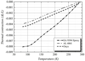
도 5 는 Onyx, Epoxy, AL 6061 소재의 극저온 열수축률 측정 결과를 나타낸 그래프이다.
도 6 은 투과도 테스트를 진행하기 위해 제작된 시편의 형상이다.
도 7 은 제작된 Onyx/epoxy 시편의 투과도 테스트 개략도 및 실험 사진이다.
도 8 (a) 및 (b) 는 Onyx/Epoxy 시편의 1 Bar부터 5 Bar까지의 압력에서 상온 및 극저온 유체 투과도 측정 결과, 도 8 (c) 및 (d) 는 Onyx/epoxy 시편의 5 Bar에서의 상온/극저온 9 시간 리크 테스트 결과이다.
도 9 는 본 발명의 실시 예에 따른 3D 프린팅-에폭시 복합 소재가 적용된 액체수소 저장탱크의 단면도이다.
도 10 은 본 발명의 실시 예에 따른 3D 프린팅-에폭시 복합 소재가 적용된 액체수소 저장탱크의 내부탱크 형상 및 재원이다.
도 11 은 Solid fill와 Triangular fill의 열응력 해석 결과이다.
도 12 는 액체질소의 수위가 90 % 정도 충전되었을 때의 열응력 분포 결과이다.
도 13 은 액체질소 수위 10 mm와 90 mm 에서의 저장탱크 온도 분포 및 최대 열응력 값을 나타낸 결과이다.
도 14 는 내부탱크에 에폭시접착제를 도포하기 전 후의 무게를 측정한 사진이다.
도 15 는 내부탱크에 온도센서, 열선(가열부재) 및 적층단열재를 부착한 상태를 나타낸 사진이다.
도 16 은 내부탱크에 외부탱크를 결합하고 에폭시접착제를 도포하여 무게를 측정한 사진이다.
도 17 은 액체수소 저장탱크 특성 평가를 위한 실험 장치를 나타낸 사진이다.
도 18 은 액체질소 주입에 따른 저장탱크 벽면 상/하단부 온도 및 기체질소 유량 측정 결과이다.1 is a schematic diagram of a cryogenic tensile tester capable of performing a tensile test in a cryogenic environment.
2 is a graph showing the results of tensile tests at room temperature/cryogenic temperatures for Onyx, Nylon, and Loctite EA 9394 Epoxy.
3 is a graph showing the modulus of elasticity at room temperature/cryogenic temperature of 3D printing materials and epoxy.
4 is a schematic diagram of a cryogenic heat shrinkage rate measurement test.
5 is a graph showing the results of measuring cryogenic heat shrinkage of Onyx, Epoxy, and AL 6061 materials.
6 is a shape of a specimen manufactured to proceed with a permeability test.
7 is a schematic diagram and experimental photos of the permeability test of the fabricated Onyx/epoxy specimen.
8 (a) and (b) are room temperature and cryogenic fluid permeability measurements at pressures from 1 Bar to 5 Bar of Onyx/Epoxy specimens, and FIGS. This is the result of the 9-hour leak test at room temperature / cryogenic temperature.
9 is a cross-sectional view of a liquid hydrogen storage tank to which a 3D printing-epoxy composite material is applied according to an embodiment of the present invention.
10 is a 3D printing-epoxy composite material according to an embodiment of the present invention is applied to the inner tank shape and material of the liquid hydrogen storage tank.
11 is a thermal stress analysis result of a solid fill and a triangular fill.
12 is a thermal stress distribution result when the liquid nitrogen level is filled to about 90%.
13 is a result showing the storage tank temperature distribution and maximum thermal stress values at liquid nitrogen levels of 10 mm and 90 mm.
14 is a photograph of measuring the weight before and after applying the epoxy adhesive to the inner tank.
15 is a photograph showing a state in which a temperature sensor, a heat wire (heating member), and a laminated insulation material are attached to the inner tank.
16 is a photograph of the weight measured by coupling the outer tank to the inner tank and applying an epoxy adhesive.
17 is a photograph showing an experimental apparatus for evaluating characteristics of a liquid hydrogen storage tank.
18 is a result of measuring the temperature of the upper and lower parts of the storage tank wall and the flow rate of gaseous nitrogen according to liquid nitrogen injection.
이하, 본 문서의 다양한 실시예가 첨부된 도면을 참조하여 기재된다. 그러나, 이는 본 문서에 기재된 기술을 특정한 실시 형태에 대해 한정하려는 것이 아니며, 본 문서의 실시예의 다양한 변경(modifications), 균등물(equivalents), 및/또는 대체물(alternatives)을 포함하는 것으로 이해되어야 한다. 도면의 설명과 관련하여, 유사한 구성요소에 대해서는 유사한 참조 부호가 사용될 수 있다.Hereinafter, various embodiments of this document will be described with reference to the accompanying drawings. However, this is not intended to limit the technology described in this document to specific embodiments, and should be understood to include various modifications, equivalents, and/or alternatives of the embodiments of this document. . In connection with the description of the drawings, like reference numerals may be used for like elements.
본 문서에서, "가진다," "가질 수 있다," "포함한다," 또는 "포함할 수 있다" 등의 표현은 해당 특징(예: 수치, 기능, 동작, 또는 부품 등의 구성요소)의 존재를 가리키며, 추가적인 특징의 존재를 배제하지 않는다.In this document, expressions such as "has," "may have," "includes," or "may include" indicate the existence of a corresponding feature (eg, numerical value, function, operation, or component such as a part). , which does not preclude the existence of additional features.
본 문서에서, "A 또는 B," "A 또는/및 B 중 적어도 하나," 또는 "A 또는/및 B 중 하나 또는 그 이상"등의 표현은 함께 나열된 항목들의 모든 가능한 조합을 포함할 수 있다. 예를 들면, "A 또는 B," "A 및 B 중 적어도 하나," 또는 "A 또는 B 중 적어도 하나"는, (1) 적어도 하나의 A를 포함, (2) 적어도 하나의 B를 포함, 또는 (3) 적어도 하나의 A 및 적어도 하나의 B 모두를 포함하는 경우를 모두 지칭할 수 있다.In this document, expressions such as “A or B,” “at least one of A and/and B,” or “one or more of A or/and B” may include all possible combinations of the items listed together. . For example, “A or B,” “at least one of A and B,” or “at least one of A or B” (1) includes at least one A, (2) includes at least one B, Or (3) may refer to all cases including at least one A and at least one B.
본 문서에서 사용된 "제 1," "제 2," "첫째," 또는 "둘째,"등의 표현들은 다양한 구성요소들을, 순서 및/또는 중요도에 상관없이 수식할 수 있고, 한 구성요소를 다른 구성요소와 구분하기 위해 사용될 뿐 해당 구성요소들을 한정하지 않는다. 예를 들면, 제 1 사용자 기기와 제 2 사용자 기기는, 순서 또는 중요도와 무관하게, 서로 다른 사용자 기기를 나타낼 수 있다. 예를 들면, 본 문서에 기재된 권리 범위를 벗어나지 않으면서 제 1 구성요소는 제 2 구성요소로 명명될 수 있고, 유사하게 제 2 구성요소도 제 1 구성요소로 바꾸어 명명될 수 있다.Expressions such as "first," "second," "first," or "second," as used in this document may modify various elements, regardless of order and/or importance, and refer to one element as It is used only to distinguish it from other components and does not limit the corresponding components. For example, a first user device and a second user device may represent different user devices regardless of order or importance. For example, without departing from the scope of rights described in this document, a first element may be called a second element, and similarly, the second element may also be renamed to the first element.
어떤 구성요소(예: 제 1 구성요소)가 다른 구성요소(예: 제 2 구성요소)에 "(기능적으로 또는 통신적으로) 연결되어(operatively or communicatively) coupled with/to)" 있다거나 "접속되어(connected to)" 있다고 언급된 때에는, 상기 어떤 구성요소가 상기 다른 구성요소에 직접적으로 연결되거나, 다른 구성요소(예: 제 3 구성요소)를 통하여 연결될 수 있다고 이해되어야 할 것이다.A component (e.g., a first component) is "(operatively or communicatively) coupled with/to" or "connected" to another component (e.g., a second component). When referred to as "connected to", it should be understood that the certain component may be directly connected to the other component or connected through another component (eg, a third component).
본 문서에서 사용된 용어들은 단지 특정한 실시 예를 설명하기 위해 사용된 것으로, 다른 실시 예의 범위를 한정하려는 의도가 아닐 수 있다. 단수의 표현은 문맥상 명백하게 다르게 뜻하지 않는 한, 복수의 표현을 포함할 수 있다. 기술적이거나 과학적인 용어를 포함해서 여기서 사용되는 용어들은 본 문서에 기재된 기술 분야에서 통상의 지식을 가진 자에 의해 일반적으로 이해되는 것과 동일한 의미를 가질 수 있다. 본 문서에 사용된 용어들 중 일반적인 사전에 정의된 용어들은, 관련 기술의 문맥상 가지는 의미와 동일 또는 유사한 의미로 해석될 수 있으며, 본 문서에서 명백하게 정의되지 않는 한, 이상적이거나 과도하게 형식적인 의미로 해석되지 않는다. 경우에 따라서, 본 문서에서 정의된 용어일지라도 본 문서의 실시 예들을 배제하도록 해석될 수 없다.Terms used in this document are only used to describe a specific embodiment, and may not be intended to limit the scope of other embodiments. Singular expressions may include plural expressions unless the context clearly dictates otherwise. Terms used herein, including technical or scientific terms, may have the same meaning as commonly understood by a person of ordinary skill in the technical field described in this document. Among the terms used in this document, terms defined in a general dictionary may be interpreted as having the same or similar meaning as the meaning in the context of the related art, and unless explicitly defined in this document, an ideal or excessively formal meaning. not be interpreted as In some cases, even terms defined in this document cannot be interpreted to exclude the embodiments of this document.
본 발명의 청구범위에서 청구하는 본 발명의 요지를 벗어남이 없이 당해 발명이 속하는 기술분야에서 통상의 지식을 가진자에 의해 다양한 변형실시가 가능한 것은 물론이고, 이러한 변형실시들은 본 발명의 기술적 사상이나 전망으로부터 개별적으로 이해되어져서는 안될 것이다.Of course, various modifications can be made by those skilled in the art without departing from the gist of the present invention claimed in the claims of the present invention, and these modifications are the technical spirit of the present invention or It should not be understood individually from the perspective.
본 발명의 실시 예에서는 FDM(Fused Deposition Modeling) 방식의 3D 프린팅 기술이 사용되었으며, 프린팅 소재(필라멘트)로는 Markforged 사(社)의 Onyx 필라멘트를 사용하였다.In the embodiment of the present invention, 3D printing technology of FDM (Fused Deposition Modeling) method was used, and Markforged's Onyx filament was used as a printing material (filament).
필라멘트는 PA6 계열 터프 나일론(Nylon) 80%에 마이크로 탄소섬유(Chopped Carbon) 20%가 혼합된 열가소성 수지일 수 있다. 이러한 소재는 카본이 20% 가량 혼합되어 있기 때문에 일반 ABS 소재보다 1.4배 정도 강도가 뛰어날 뿐만 아니라, 열에 강하고 내화학성이 뛰어나다. 따라서, 극저온 환경에서의 열수축이 적어 액체수소 저장탱크로 사용하기에 적합하다.The filament may be a thermoplastic resin in which 80% of PA6-based tough nylon and 20% of chopped carbon are mixed. Since these materials contain about 20% of carbon, they are 1.4 times stronger than general ABS materials, as well as strong against heat and excellent in chemical resistance. Therefore, it is suitable for use as a liquid hydrogen storage tank due to low heat shrinkage in a cryogenic environment.
본 발명의 실시 예에서는 내부탱크에 도포하는 제1에폭시접착제로써 Loctite 사의 복합재 접착용 에폭시인 EA 9394 Aero를 사용하였다. 이 에폭시는 항공우주 구조용 접착제로 접착력, 기계적 특성 및 내화학성이 뛰어나 복합재료의 구조용 접착제로 많이 사용된다. 또한, 다른 에폭시 수지 제품들과 달리 상대적으로 접착력이 우수하고, 열수축이 Onyx 소재(3D 프린팅 소재)와 비슷하기 때문에 극저온 환경에서 수축에 의한 열응력이 덜 발생한다. 따라서, 극저온 환경에 노출 될 내부 저장용기의 접착 및 누설 방지 용도로 사용하기에 적합하다.In the embodiment of the present invention,
본 발명의 실시 예에서는 외부탱크에 도포하는 제2에폭시접착제로써 Loctite 사의 복합재 접착용 에폭시인 EA 9396 Aero를 사용하였다. EA 9394 Aero 와 EA 9396 Aero는 기계적 물성은 비슷하지만, EA 9396이 EA 9394 보다 상대적으로 점도가 낮다. 외부탱크는 내부탱크와 같은 극저온 환경이 아니며, 내부(외부탱크와 내부탱크 사이의 공간)에 압력이 크게 발생하는 것이 아니기 때문에 기밀성만 확보하여 진공 환경만 조성해주면 된다. 따라서, 최대한 점도가 낮으며 기공이 적게 발생하는 에폭시가 적합하며, EA 9396의 경우 점도가 매우 낮아 에폭시 사이사이 존재하는 기포들을 제거하는 탈포할 수 있기 때문에 외부탱크용 제2에폭시접착제로 사용하였다.In the embodiment of the present invention, EA 9396 Aero, an epoxy for bonding composite materials from Loctite, was used as the second epoxy adhesive applied to the external tank.
1. 액체수소 저장탱크의 물성 측정1. Measurement of physical properties of liquid hydrogen storage tank
① 인장시험① Tensile test
액체질소를 사용하여 -196 ℃의 온도에서 인장시험을 진행하였다.A tensile test was performed at a temperature of -196 °C using liquid nitrogen.
인장시험기는 큐로 社의 만능재료시험기인 QRUTS-S100을 사용하였다.As a tensile tester, QRUTS-S100, a universal material tester from Curo, was used.
상기 인장시험기로는 상온에서의 인장시험밖에 할 수 없기 때문에, 액체질소 내부에서 인장시험을 할 수 있게 내부에 수조를 설치하여 액체질소를 주입 할 공간을 확보하였다.Since the tensile tester can only perform a tensile test at room temperature, a water tank was installed inside to secure a space for injecting liquid nitrogen so that a tensile test can be performed inside the liquid nitrogen.
도 1 은 극저온 환경에서 인장시험을 진행할 수 있는 극저온 인장시험기의 개략도이다.1 is a schematic diagram of a cryogenic tensile tester capable of performing a tensile test in a cryogenic environment.
상부 및 하부 지그와 시편은 액체질소 수조 안에 위치하게 되며, 상부, 하부 지그 중앙과 시편 중앙에 온도센서가 위치한다. 온도센서는 E-type Thermo couple을 사용하였다.The upper and lower jigs and specimens are placed in a liquid nitrogen bath, and temperature sensors are located in the center of the upper and lower jigs and the specimen. The temperature sensor used an E-type Thermo couple.
수조 내부에 액체질소를 채운 다음, 상/하단부 지그와 시편이 액체질소 온도로 수렴하여 열적 평형을 이룰 때까지 기다린다. 그 후, 인장시험을 진행하며 최상단에 위치한 Load cell을 통하여 인장 시 발생 하는 힘을 측정하고, Crosshead를 통하여 변위를 측정한다.After filling the inside of the water tank with liquid nitrogen, wait until the upper and lower jigs and the specimen converge to the liquid nitrogen temperature to achieve thermal equilibrium. After that, a tensile test is performed, the force generated during tension is measured through the load cell located at the top, and the displacement is measured through the crosshead.
시험에 사용 될 시편의 규격은 ASTM D 638 규격을 사용하였으며, 3D 프린터로 출력하였다.The standard of the specimen to be used for the test was the ASTM D 638 standard, and it was printed with a 3D printer.
액체질소를 주입하게 되면 시간이 지남에 따라 하부 지그의 온도센서부터 온도가 감소하게 되고 점차 수렴하여 상부 온도센서 까지 77 K으로 수렴하게 된다. 3개의 온도센서가 모두 수렴하고 나면 인장시험을 진행하며, 2 mm/min의 속도로 하중을 부여하였다.When liquid nitrogen is injected, the temperature decreases from the temperature sensor of the lower jig over time and gradually converges to 77 K to the upper temperature sensor. After all three temperature sensors converged, a tensile test was performed, and a load was applied at a rate of 2 mm/min.
인장시험에서 얻어지는 Force-Displacement Curve에 대하여 Strain 은 다음과 같이 산출 할 수 있다.For the force-displacement curve obtained from the tensile test, the strain can be calculated as follows.
![]()
![]()
여기서, L은 Gauge length이며, ΔL의 경우 초기길이 대비 늘어난길이, ε은 변형률이다. 또한, Stress의 경우 시편의 인장 방향 단면적인 19 mm 2 에 대하여 다음과 같이 산출 가능하다.Here, L is the gauge length, in the case of ΔL, the length increased compared to the initial length, and ε is the strain. In addition, in the case of stress, it can be calculated as follows for the cross-sectional area of the specimen in the tensile direction of 19
![]()
![]()
이후, 수학식 3의 Stress, Strian, Young’s modulus 관계식에 의해 Young’s modulus를 산출 할 수 있다.Then, Young's modulus can be calculated by the relationship between stress, Strian, and Young's modulus in
![]()
![]()
도 2 는 Onyx, Nylon 및 Loctite EA 9394 Epoxy의 상온/극저온 인장시험 결과 그래프이다.2 is a graph showing the results of tensile tests at room temperature/cryogenic temperatures for Onyx, Nylon, and
상기 세가지 재료 모두 상온에 비해 극저온 환경에서 변형률이 감소하였으며, 이는 온도가 감소함에 따라 소재가 취성화(Brittle)되었다고 볼 수 있다. 또한, 모든 재료에서 강도가 증가하였으며 EA 9394 에폭시와 Nylon보다 Onxy가 강도 증가 폭이 조금 더 큰 것을 볼 수 있다.In all three materials, the strain decreased in the cryogenic environment compared to room temperature, which can be seen that the material became brittle as the temperature decreased. In addition, the strength increased in all materials, and the strength increase of Onxy was slightly greater than that of
도 3 은 3D 프린팅 재료및 에폭시의 상온/극저온 탄성계수를 나타낸 그래프이다. 온도가 감소함에 따라 모든 재료에서 탄성계수가 증가하였다.3 is a graph showing the modulus of elasticity at room temperature/cryogenic temperature of 3D printing materials and epoxy. As the temperature decreased, the modulus of elasticity increased in all materials.
종합적으로, 3D 프린팅 소재 및 에폭시는, 극저온 환경에서 상온 대비 인장강도가 약 1.2 ~ 3배 증가하였으며, 탄성계수가 약 3 ~ 9배 증가하는 것을 확인하였다. 이에 따라, 극저온 유체 저장탱크의 소재는 Onyx와 Nylon 중 극저온 환경에서 인장강도 및 탄성계수가 30 ~ 40 % 더 큰 Onyx를 채택하였다.Overall, it was confirmed that the tensile strength of the 3D printing material and the epoxy increased by about 1.2 to 3 times compared to room temperature in a cryogenic environment, and the modulus of elasticity increased by about 3 to 9 times. Accordingly, among Onyx and Nylon, Onyx, which has 30 to 40% higher tensile strength and modulus of elasticity in a cryogenic environment, was selected as the material for the cryogenic fluid storage tank.
② 열수축률 측정② Measurement of heat shrinkage rate
Onyx와 Epoxy의 경우 극저온 환경에서의 열수축률 관련 데이터가 없어 측정이 필요하다.In the case of Onyx and Epoxy, there is no data related to thermal shrinkage in a cryogenic environment, so measurement is required.
열수축률을 알기 위해 측정해야 하는 변수는 소재의 변위 및 온도이다. 변위(displacement)는 스트레인 게이지를 사용하여 측정하였으며, 극저온 환경에서도 사용가능한 Kyowa 사의 스트레인 게이지를 사용하였다.The variables that need to be measured to determine the heat shrinkage rate are the displacement and temperature of the material. Displacement was measured using a strain gauge, and a strain gauge from Kyowa, which can be used in a cryogenic environment, was used.
시편의 온도는 E-type Thermo couple 온도센서를 이용하여 계측기를 통해 측정하였다.The temperature of the specimen was measured through a measuring instrument using an E-type Thermo couple temperature sensor.
측정 시편의 경우 Onyx 소재는 3D 프린터로 출력하였으며, Epoxy 시편의 경우 시편 틀에 넣어 제작하였다.In the case of the measurement specimen, the Onyx material was printed with a 3D printer, and the Epoxy specimen was manufactured by putting it in a specimen mold.
일반적으로 재료는 온도가 증가함에 따라 팽창하고 온도가 감소함에 따라 수축한다. 온도가 감소함에 따라 재료가 수축하는 정도는 다음과 같이 나타낼 수 있다.In general, materials expand as temperature increases and contract as temperature decreases. The amount of shrinkage of a material as the temperature decreases can be expressed as:
![]()
![]()
여기서, L은 Strain gauge의 초기 길이이며, ΔL의 경우 초기길이 대비 줄어든 길이, ε은 변형률이다.Here, L is the initial length of the strain gauge, ΔL is the reduced length compared to the initial length, and ε is the strain.
도 4 는 극저온 열수축률 측정 시험의 개략도이다. 온도가 감소함에 따른 소재의 수축 정도를 측정하기 위해서는 재료의 극저온 환경 구축이 필요하다. 또한, 열수축률은 충분한 시간간격을 두고 측정해야 정확한 값을 얻을 수 있다. 따라서, 밀폐된 용기 내부에 액체 질소를 조금씩 분사하여 극저온 환경을 모사하는 방식을 채택하였다.4 is a schematic diagram of a cryogenic heat shrinkage rate measurement test. In order to measure the degree of shrinkage of a material as the temperature decreases, it is necessary to establish a cryogenic environment for the material. In addition, the heat shrinkage rate should be measured at a sufficient time interval to obtain an accurate value. Therefore, a method of simulating a cryogenic environment was adopted by spraying liquid nitrogen little by little into the sealed container.
용기 상단에 액체질소 분사 노즐 2개와 써큘레이터가 위치하며 분사노즐을 통해 액체질소가 조금씩 분사된다. 분사된 액체질소는 써큘레이터를 통해 기체질소로 상변화 하면서 용기 내부 온도를 낮추게 된다. 동시에 서서히 냉각되는 시편의 온도와 변위를 동시에 실시간으로 측정한다. 시편의 온도가 액체질소의 온도인 77 K 근처까지 수렴하게 되면 시험은 종료된다.Two liquid nitrogen spray nozzles and a circulator are located at the top of the container, and liquid nitrogen is sprayed little by little through the spray nozzles. The injected liquid nitrogen is phase-changed into gaseous nitrogen through the circulator, lowering the internal temperature of the container. At the same time, the temperature and displacement of the slowly cooled specimen are simultaneously measured in real time. The test is terminated when the temperature of the specimen converges to near 77 K, which is the temperature of liquid nitrogen.
도 5 는 Onyx, Epoxy, AL 6061 소재의 극저온 열수축률 측정 결과를 나타낸 그래프이다.5 is a graph showing the results of measuring cryogenic heat shrinkage of Onyx, Epoxy, and AL 6061 materials.
열수축률 신뢰성을 위해 극저온에서 열수축률이 알려진 AL 6061 금속에 대하여 열수축률을 측정한 후 비교하여 신뢰성을 검증하였다. 두 소재 모두 온도가 감소함에 따라 수축하는 변위가 조금씩 증가하였으며, 77 K 근처까지 온도가 떨어졌을 때 Onyx는 초기길이 대비 약 0.4%의 수축을 보였으며, Epoxy의 경우 초기길이 대비 약 0.8%의 수축률이 측정되었다.For reliability of thermal contraction rate, the thermal shrinkage rate of AL 6061 metal, whose thermal shrinkage rate is known at cryogenic temperatures, was measured and compared to verify reliability. In both materials, the shrinking displacement gradually increased as the temperature decreased, and when the temperature dropped to around 77 K, Onyx showed a shrinkage of about 0.4% compared to the initial length, and in the case of Epoxy, the shrinkage rate was about 0.8% compared to the initial length. has been measured
③ 유체 투과성 측정③ Fluid permeability measurement
극저온 환경에서 액체 수소를 사용하기 위해 필수적으로 검토해야할 사항 중 하나는 소재의 유체 투과성이다.One of the essential considerations for using liquid hydrogen in a cryogenic environment is the fluid permeability of the material.
수소는 폭발성이 있는 기체이기 때문에 탱크 외부로 가스가 새어나가게 되면 폭발의 위험이 있다. 따라서, 사용되는 소재에 대하여 상온 및 극저온 환경에서의 유체 투과도를 확인해야 한다.Since hydrogen is an explosive gas, there is a risk of explosion if the gas leaks out of the tank. Therefore, it is necessary to check the fluid permeability of the material used in the room temperature and cryogenic environment.
유체 투과도의 기준에 대해서는 정확한 기준이 없기 때문에 입자 가속기와 KSTAR에 적용되는 기준을 참고하여, ![]()
![]()
도 6 및 표 1 은 투과도 테스트를 진행하기 위해 제작된 시편의 형상 및 재원이다.Figure 6 and Table 1 are the shape and material of the specimen manufactured to proceed with the permeability test.
실제 제작되는 복합재 탱크의 조건과 동일하게 하기 위해 Onyx에 EA 9394 Aero Epoxy를 도포하여 시편을 제작하였다. 둥근 원판 형태의 Onyx 시편을 3D 프린터로 제작 후, 안쪽 면에 Epoxy를 도포하였다.In order to match the conditions of the actual composite tank, specimens were prepared by applying
도 7 은 제작된 Onyx/epoxy 시편의 투과도 테스트 개략도 및 실험 사진이다.7 is a schematic diagram and experimental photos of the permeability test of the fabricated Onyx/epoxy specimen.
투과도 테스트를 하기 위한 사용 유체로는 헬륨을 사용하였다. 헬륨은 수소 원자 다음으로 입자가 작은 원자로 투과도를 알아보기에 용이하다.Helium was used as a fluid used for permeability testing. Helium is an atom with a smaller particle size next to the hydrogen atom, and its permeability is easy to determine.
도 7 을 살펴보면, 입구와 출구로 구성된 경로상에 테스트 시편을 두고 시편 외부로 가스가 세지 않도록 CF Flange를 통하여 체결되어 있다. 상기 입구에서 헬륨을 가압하고 출구쪽에서 Leak Detector를 통해 헬륨을 검출한다.Referring to FIG. 7, the test specimen is placed on a path composed of an inlet and an outlet and is fastened through the CF Flange so that gas does not leak out of the specimen. Helium is pressurized at the inlet and helium is detected at the outlet side through a leak detector.
온도센서와 압력센서를 통해 내부 배관의 압력 및 시편의 온도를 측정하며, 리크디텍터의 정밀한 측정을 위해 진공펌프를 사용하여 출구 경로상의 진공도를 높게 유지하였다.The pressure of the internal pipe and the temperature of the specimen were measured through a temperature sensor and a pressure sensor, and a vacuum pump was used to maintain a high degree of vacuum on the exit path for precise measurement of the leak detector.
도 8 (a) 및 (b) 는 Onyx/Epoxy 시편의 1 Bar부터 5 Bar까지의 압력에서 상온 및 극저온 유체 투과도 측정 결과이다. 약 1000초 간격으로 1 Bar부터 5 Bar까지 헬륨 압력을 증가시켰으며, 상온과 극저온두 경우 모두 5 Bar까지 ![]()
![]()
도 8 (c) 및 (d) 는 Onyx/epoxy 시편의 5 Bar에서의 상온/극저온 9 시간 리크 테스트 결과이다. 장시간 운전을 해야 하는 드론용 액체수소 저장용기 특성상 충분히 긴 시간 동안 Leak rate를 확인할 필요가 있다. 따라서, 최대 설정 압력인 5 Bar에서의 상온과 극저온에서의 Leak rate를 측정 하였다. 측정 결과 상온과 극저온 모두 9시간 동안 ![]()
![]()
상온 및 극저온 유체 투과도 측정 결과는 표 2에 종합하였다.The room temperature and cryogenic fluid permeability measurement results are summarized in Table 2.
Leak rate (mbar·L/s)1-5 Bar Max.
Leak rate (mbar L/s)
2. 액체수소 저장탱크의 설계 사양2. Design specifications of liquid hydrogen storage tank
① 목표 사양 설계① Target specification design
도 9 는 본 발명의 실시 예에 따른 3D 프린팅-에폭시 복합 소재가 적용된 액체수소 저장탱크의 단면도이다.9 is a cross-sectional view of a liquid hydrogen storage tank to which a 3D printing-epoxy composite material is applied according to an embodiment of the present invention.
도 10 은 본 발명의 실시 예에 따른 3D 프린팅-에폭시 복합 소재가 적용된 액체수소 저장탱크의 내부탱크 형상 및 재원이다.10 is a 3D printing-epoxy composite material according to an embodiment of the present invention is applied to the inner tank shape and material of the liquid hydrogen storage tank.
3D 프린터를 통하여 출력 가능한 크기에는 제한이 있기 때문에 소형 어플리케이션에 적용 가능하도록 목표를 설정하였다. 벽면 두께의 경우 제작성을 고려하여 4.8 mm로 설정하였으며, 액체수소 저장탱크의 용량은 약 1.1 L 로 산출되었다.Since there is a limit to the size that can be printed through a 3D printer, the goal was set to be applicable to small applications. In the case of wall thickness, it was set to 4.8 mm in consideration of manufacturability, and the capacity of the liquid hydrogen storage tank was calculated to be about 1.1 L.
벽면 두께의 내부 Filament 채움 정도를 Triangular fill(37%)로 설정하여 무게를 최소화하였으며, 내부탱크는 극저온 액체 저장을 위한 저장용기로써, 외부탱크는 진공 환경을 구성해 주는 진공용기로써 구비된다. 본 발명의 실시 예에 따른 3D 프린팅-에폭시 복합 소재가 적용된 액체수소 저장탱크의 총 무게는 약 870 g으로 측정되었다.The weight was minimized by setting the fill level of the inner filament of the wall thickness to Triangular fill (37%). The total weight of the liquid hydrogen storage tank to which the 3D printing-epoxy composite material was applied according to an embodiment of the present invention was measured to be about 870 g.
소형 드론부터 대형 무인기까지 일반적으로 사용되는 연료전지 배터리의 정격출력은 작게는 300 W부터 많게는 1000 W 까지 사용된다. 위 사양을 기준으로 연료전지가 요구하는 기체수소 유량 및 그에따른 유지시간을 산출할 수 있다. 표 3 은 1.1 L 액체수소 저장탱크에 대하여 수위 90 % 충전되었을 때, 300 W부터 1000 W 까지 적용가능한 연료전지 배터리의 사양이다.The rated power of fuel cell batteries commonly used from small drones to large unmanned aerial vehicles ranges from 300 W to 1000 W. Based on the above specifications, the flow rate of gaseous hydrogen required by the fuel cell and the corresponding maintenance time can be calculated. Table 3 is the specification of the fuel cell battery applicable from 300 W to 1000 W when the water level is charged to 90% for the 1.1 L liquid hydrogen storage tank.
충전된 액체수소 저장탱크에서의 액체수소는 지속적으로 증발하며, 증발량은 외부에서 들어오는 열침입량에 비례한다.Liquid hydrogen in the filled liquid hydrogen storage tank continuously evaporates, and the amount of evaporation is proportional to the amount of heat intrusion from the outside.
저장탱크의 액체 수소 유지 시간을 최대한 늘리고, 버려지는 기체수소의 양을 최소화하기 위해 외부에서 들어오는 열침입을 최소화해야 한다. 기본적으로 입/출구 배관을 통한 전도 열침입, 외부 용기 면적에 대한 복사 열침입 등이 기저 열부하가 된다.In order to maximize the liquid hydrogen retention time in the storage tank and minimize the amount of gaseous hydrogen that is wasted, heat intrusion from the outside must be minimized. Basically, the conduction heat intrusion through the inlet/outlet piping and the radiant heat intrusion to the outer container area become the base heat load.
먼저, 전도 열침입은 입/출구 배관으로의 상온에서부터 열침입이 있으며, 다음의 푸리에의 열전도 법칙에 의해 계산 할 수 있다.First, conduction heat penetration is heat penetration from room temperature to the inlet/outlet pipe, and can be calculated by the following Fourier's heat conduction law.

여기서, sus 316L 재질에 대하여 1/4 inch 사이즈의 입/출구 배관 각각의 전도 열침입량은 약 0.5 W로 산출되었다.Here, for the sus 316L material, the conduction heat penetration of each inlet/outlet pipe of 1/4 inch size was calculated to be about 0.5 W.
복사 열침입은 전도나 대류에 비해 상대적으로 큰 비중을 차지하기 때문에 다층박막단열재(MLI, multi-layer insulation)을 통하여 최소화 하였다.Since radiant heat penetration accounts for a relatively large proportion compared to conduction or convection, it was minimized through multi-layer insulation (MLI).
외부 진공용기의 상온에서부터 내부 저장용기의 극저온 온도까지 두 온도 사이에 발생하는 복사열전달은 수학식 6으로 표현된다.Radiant heat transfer occurring between the two temperatures from the room temperature of the external vacuum container to the cryogenic temperature of the internal storage container is expressed by
여기서 σ는 스테판-볼츠만 상수, ε는 방사율(emissivity), T1, T1는 열전달 대상의 온도, A는 열전달 면적이다. 일반적으로 T2는 대기 온도가 된다.Here, σ is the Stefan-Boltzmann constant, ε is the emissivity, T1, T1 are the temperature of the heat transfer target, and A is the heat transfer area. Typically, T2 will be the ambient temperature.
![]()
![]()
MLI가 없을 경우, 내부 저장용기 소재인 Onyx의 방사율을 모르기 때문에 복사 열침입을 계산 할 수 없다. 하지만 MLI를 시공하였을 때에는 MLI 매수에 따른 복사 열침입량이 알려져 있기 때문에 복사 열침입을 산출할 수 있다. MLI의 매수에 따른 복사 열침입량은 수학식 7과 같다Without the MLI, the radiant heat penetration cannot be calculated because the emissivity of Onyx, the internal storage material, is not known. However, when the MLI is constructed, the radiant heat intrusion can be calculated because the amount of radiant heat intrusion according to the number of MLI is known. The amount of radiant heat penetration according to the number of MLI is shown in
![]()
![]()
수학식 7을 참조하여 MLI가 10매 정도 시공되었을 때의 복사 열침입량 12 W/m^2 에 대하여, 및 액체수소 저장용기 전체 면적 0.067 m^2 에 해당하는 복사 열침입량은 약 0.8 W로 산출되었다.Referring to
대류 열침입의 경우, 용기 내부를 고진공 상태로 유지하여 없다고 가정하였다.In the case of convective heat penetration, it was assumed that there was no convective heat penetration by maintaining the inside of the container in a high vacuum state.
열부하에 따른 액체수소의 증발량은 수학식 8에 따라 계산 할수 있다The amount of evaporation of liquid hydrogen according to the heat load can be calculated according to

여기서, ![]()
![]()
![]()
![]()
액체수소의 증발잠열은 443 kJ/kg이며, 앞서 산출된 액체수소 저장탱크의 기본 열부하인 1.8 W에 대해 액체수소 증발률을 산출하면 약 0.0041 g/s이다. 이는 액체수소 증발잠열에 의해 초당 약 0.0041 g 의 기체수소가 증발하는 것을 의미하며, 표 3 의 연료전지 요구 사양에 따라 정격출력 300 W 이상의 연료전지 배터리에 적용가능한범위이다. 실제 실험과의 비교를 위해 액체질소 증발잠열(199 kJ/kg) 에 대한 증발량을 산출하면 약 0.009 g/s로 산출된다.The latent heat of vaporization of liquid hydrogen is 443 kJ/kg, and when the liquid hydrogen evaporation rate is calculated for the basic heat load of 1.8 W of the liquid hydrogen storage tank calculated above, it is about 0.0041 g/s. This means that about 0.0041 g of gaseous hydrogen is evaporated per second by the latent heat of vaporization of liquid hydrogen, and is a range applicable to fuel cell batteries with a rated output of 300 W or more according to the fuel cell requirements in Table 3. For comparison with the actual experiment, when calculating the amount of evaporation for the latent heat of vaporization of liquid nitrogen (199 kJ/kg), it is calculated as about 0.009 g/s.
② 열응력 해석② Thermal stress analysis
액체수소 저장탱크 내부에 액체수소를 충전하게 되면, 초기 상온의 탱크 벽면과 극저온의 액체수소의 열전달에 의해 액체수소의 증발이 일어나며, 충전되는 양과 증발되는 양의 차이만큼 수위가 상승하게 된다.When liquid hydrogen is filled inside the liquid hydrogen storage tank, evaporation of liquid hydrogen occurs due to heat transfer between the tank wall at the initial room temperature and the cryogenic liquid hydrogen, and the water level rises by the difference between the charged amount and the evaporated amount.
또한, 수위 상승에 따라 탱크 벽면에서의 온도 구배가 형성되고, 각 소재의 온도에 따른 수축 정도에 따라 열응력이 발생한다. 수축률이 서로 다르기 때문에 각 위치에서의 변위가 모두 다르며, 이로 인해 열응력이 과도하게 발생할 수 있다.In addition, as the water level rises, a temperature gradient is formed on the tank wall, and thermal stress is generated according to the degree of contraction according to the temperature of each material. Since the shrinkage rates are different, the displacements at each location are all different, which can cause excessive thermal stress.
과도한 열응력 발생으로 인해 미세한 크랙이나 파괴가 일어날 경우, 내부 수소의 누설이 발생하게 되고, 저장탱크로서의 역할을 하지못하게 된다. 따라서, 액체수소 저장탱크의 극저온 환경에서의 열적 건전성 평가를 위해 열응력 해석이 필요하다. 해석 프로그램은 구조 해석과 열해석을 커플링하여 시뮬레이션 하기에 적합한 Comsol Multiphysics를 사용하였다.When fine cracks or destruction occur due to excessive thermal stress, internal hydrogen leakage occurs, and the tank cannot function as a storage tank. Therefore, thermal stress analysis is needed to evaluate the thermal integrity of the liquid hydrogen storage tank in a cryogenic environment. The analysis program used Comsol Multiphysics, which is suitable for simulation by coupling structural analysis and thermal analysis.
극저온 유체 저장탱크의 열응력 해석은 크게 2가지로 볼 수 있다(액체질소를 충전한다고 가정했을 때).Thermal stress analysis of a cryogenic fluid storage tank can be largely divided into two types (assuming liquid nitrogen is filled).
첫번째는, 저장탱크 내부의 최대 열응력이 발생하는 부분을 확인하는 것이다. 저장탱크 내부에 액체질소가 90 % 이상 충전되었을 때, 저장 탱크 내부 벽면 대부분의 온도는 액체질소의 온도인 77 K 근처로 형성된다. 이때, 외부 벽면 및 입/출구 수소 충전 포트 와의 열전달에 의한 최대 열응력 발생 지점을 확인한다.The first is to identify the part where the maximum thermal stress occurs inside the storage tank. When the inside of the storage tank is filled with 90% or more of liquid nitrogen, the temperature of most of the inner walls of the storage tank is formed near 77 K, which is the temperature of liquid nitrogen. At this time, the point where the maximum thermal stress occurs due to heat transfer between the outer wall and the inlet/outlet hydrogen charging port is checked.
두 번째는, 액체질소 충전 시 액체질소 수위에 따른 열응력 변화를 비교하는 것이다. 액체질소가 충전됨에 따라 수위는 점차 증가하며, 수위가 90 % 이상 충전 되었을 때는 내부 벽면의 온도가 77 K 근처로 형성되지만, 수위가 10 % 정도 형성되었을 때에는 저장탱크의 상단부와 하단부의 온도 차가 발생하게 되며 내부 벽면에 온도 구배가 생기게 된다. 온도 변화에 따른 수축률의 변화가 크다면, 저장탱크 하단부의 수축 변위가 크기 때문에 수위 90 % 충전 시 보다 더 큰 열응력이 발생 할 수 있다.The second is to compare the thermal stress change according to the liquid nitrogen level during liquid nitrogen filling. As the liquid nitrogen is filled, the water level gradually increases, and when the water level is filled more than 90%, the temperature of the inner wall is formed around 77 K, but when the water level is about 10% formed, the temperature difference between the upper part and the lower part of the storage tank occurs. This creates a temperature gradient on the inner wall. If the change in shrinkage rate due to temperature change is large, a larger thermal stress may occur than when the water level is filled to 90% because the shrinkage displacement of the lower part of the storage tank is large.
액체수소 저장탱크 열응력 해석 모델은 실제 크기와 동일하게 모델링하였으며, 축을 중심으로 대칭을 갖기 때문에 전체 용기 크기에 대하여 1/4 모델로 해석을 수행하였다.The liquid hydrogen storage tank thermal stress analysis model was modeled the same as the actual size, and because it has symmetry around the axis, the analysis was performed as a 1/4 model for the entire container size.
구속 조건으로는 축을 경계로 Symmetric 조건을 부가하였으며, sus 끝단에 z축으로의 변위를 고정시키는 조건을 부가하였다. 온도 조건으로는 입/출구 포트인 sus tube 맨 끝단에 293 K 의 조건을 부가하였으며, 내부 용기 벽면에 77 K 조건을 부가하였다. 실제 실험은 액체질소로 진행하기 때문에 비교를 위하여 액체질소의 온도를 적용하였다.As a constraint condition, a symmetric condition was added with the axis as the boundary, and a condition to fix the displacement in the z-axis was added to the end of the sus. As the temperature condition, a 293 K condition was added to the end of the sus tube, which is an inlet/outlet port, and a 77 K condition was added to the inner container wall. Since the actual experiment is conducted with liquid nitrogen, the temperature of liquid nitrogen was applied for comparison.
적용된 소재로는 입/출구 포트로 sus 316L, 액체수소 저장탱크 본체인 Onyx, 저장탱크에 도포될 Loctite EA 9394 Epoxy를 적용하였다. SUS 316L의 경우 Comsol Multiphysics 내부에 있는 온도에 따른 물성치를 적용하였으며, Onyx와 Epoxy의 경우 측정한 Thermal strain 및 Young’s modulus 실험 값을 사용하였으며, 나머지 물성치는 제조사에서 제공하는 데이터를 사용하였다. Onyx와 EA 9394 Aero Epoxy에 대하여 해석에 적용된 물성치는 다음 표 4과 같다.As materials applied, sus 316L for the inlet/outlet port, Onyx for the liquid hydrogen storage tank body, and
액체수소 저장용기의 무게를 최소화 하기 위해 액체수소 저장탱크 두께에 대하여 내부 채움 정도를 Triangular infill (37 %)로 결정하였다. Triangular infill 비율은 경량성 및 내압성능을 비교하여 적절한 범위 내에서 조절할 수 있다. 액체수소 저장탱크의 무게를 줄이기 위해선 내부채움 정도를 작게 할수록 유리하지만, 극저온 환경에서 수축 시, 변형에 대한 저항이 줄어들어 크랙이 발생할 수 있다. 따라서, 내부채움 정도를 Solid fill (100 %)로 했을 때와 Triangular infill (37 %)로 했을 때의 열응력을 비교하여야 한다.In order to minimize the weight of the liquid hydrogen storage container, the internal filling level was determined as triangular infill (37%) for the thickness of the liquid hydrogen storage tank. The triangular infill ratio can be adjusted within an appropriate range by comparing lightness and pressure resistance. In order to reduce the weight of the liquid hydrogen storage tank, it is advantageous to reduce the degree of internal filling, but when shrinking in a cryogenic environment, resistance to deformation is reduced and cracks may occur. Therefore, it is necessary to compare the thermal stress of solid fill (100%) and triangular infill (37%) as the degree of internal filling.
도 11 에서 보이는 바와 같이 Solid fill와 Triangular fill의 열응력 해석 결과 전반적으로 비슷한 응력 분포를 보였다.As shown in FIG. 11, the thermal stress analysis results of the solid fill and the triangular fill showed generally similar stress distributions.
Solid fill 에서 Epoxy 부분의 응력이 Triangular fill에서 Epoxy 부분의 응력보다 크게 발생하였으며, 이는 전체 형상에서 Solid fill이 Onyx 부피를 더 많이 가짐으로써 극저온 환경에서 더 많이 수축하는 영향인 것으로 판단된다. 하지만, Onyx 부분에서의 전체적인 응력은 Triangular fill이 미미하게 더 높은 것으로 확인되었다.The stress of the epoxy part in the solid fill was higher than that of the epoxy part in the triangular fill. However, the overall stress in the onyx part was found to be slightly higher for the triangular fill.
도 12 는 액체질소의 수위가 90 % 정도 충전되었을 때의 열응력 분포 결과이다.12 is a thermal stress distribution result when the liquid nitrogen level is filled to about 90%.
최대 열응력 발생 지점은 sus tube에서 발생하였으며, 약 175 MPa 정도이다. sus tube를 둘러싸고 있는 Onyx와 Epoxy가 복합적으로 수축하면서 sus tube에 열응력이 발생하게 된다. SUS tube를 제외한 저장탱크의 전반적인 열응력은 0 ~ 33 MPa 정도로 확인되었다.The maximum thermal stress generation point occurred in the sus tube and was about 175 MPa. As Onyx and Epoxy surrounding the sus tube contract in a complex way, thermal stress occurs in the sus tube. The overall thermal stress of the storage tank except for the SUS tube was confirmed to be about 0 to 33 MPa.
액체수소 저장탱크 내부 유체 수위가 서서히 증가함에 따라 발생하는 최대 열응력 크기도 변화하게 된다. 수위 증가에 따른 최대 열응력 변화를 확인하기 위해 저장탱크 내부 유체 수위에 따른 열응력 해석을 진행하였다. 유체의 수위는 10 mm부터 90 mm 까지 10 mm 단위로 설정하였다.As the fluid level in the liquid hydrogen storage tank gradually increases, the magnitude of the maximum thermal stress generated also changes. In order to confirm the change in maximum thermal stress according to the increase in water level, thermal stress analysis was performed according to the fluid level in the storage tank. The fluid level was set in increments of 10 mm from 10 mm to 90 mm.
도 13 은 액체질소 수위 10 mm와 90 mm 에서의 저장탱크 온도 분포 및 최대 열응력 값을 나타낸 결과이다.13 is a result showing the storage tank temperature distribution and maximum thermal stress values at liquid nitrogen levels of 10 mm and 90 mm.
표 5 는 각 수위에서의 최대 열응력 값 및 SUS tube를 제외한 최대 열응력 값이다.Table 5 shows the maximum thermal stress values at each water level and the maximum thermal stress values excluding SUS tubes.
수위가 증가함에 따라 저장탱크 내부 벽면의 온도 분포도 변화하는 것을 확인할 수 있으며, 전도 열전달에 의해 탱크 하단부터 상부까지 탱크 벽면이 냉각된다.It can be seen that the temperature distribution on the inner wall of the storage tank changes as the water level increases, and the tank wall is cooled from the bottom of the tank to the top by conduction heat transfer.
수위가 증가함에 따라 sus tube의 최대 열응력이 증가하였다. 수위가 증가함에 따라, 저장탱크 내부 sus tube를 감싸고 있는 Epoxy와 Onyx의 수축률이 증가하여 SUS tube의 최대 열응력이 증가하게 된다. 수위가 90 % 일때, 최대 170.8 MPa가 발생하였으며, 이는 SUS tube에서 발생하는 열응력이다.As the water level increased, the maximum thermal stress of the sus tube increased. As the water level increases, the shrinkage rate of Epoxy and Onyx surrounding the sus tube inside the storage tank increases, increasing the maximum thermal stress of the SUS tube. When the water level was 90%, a maximum of 170.8 MPa occurred, which is the thermal stress generated in the SUS tube.
반대로 SUS tube를 제외한 최대 열응력 변화에서는 수위가 증가함에 따라, 전반적인 저장탱크의 열응력이 비슷한 경향을 보였다. 이는 수위가 증가하더라도, 탱크의 전반적인 최대 열응력은 약 33 MPa 이하를 유지한다는 것을 의미한다.Conversely, in the change of maximum thermal stress except for the SUS tube, as the water level increased, the thermal stress of the overall storage tank showed a similar tendency. This means that even if the water level increases, the overall maximum thermal stress of the tank remains below about 33 MPa.
3. 3D 프린팅-에폭시 복합 소재가 적용된 액체수소 저장탱크 제조방법3. Liquid hydrogen storage tank manufacturing method using 3D printing-epoxy composite material
① 내부탱크 제작① Manufacture of inner tank
앞서 설계된 액체수소 저장탱크 모델을 토대로 3D 프린터를 통하여 내부탱크를 제작할 수 있다.Based on the previously designed liquid hydrogen storage tank model, the inner tank can be manufactured through a 3D printer.
벽면 두께에 대하여 Triangular infill (37 %)가 적용되어 출력되었다.Triangular infill (37%) was applied and printed for the wall thickness.
극저온 환경에서의 내부탱크의 크랙 및 누설을 최대한 방지하기 위해 내부탱크를 한 몸체로 출력하였고, 내부탱크가 원통형 형상이기 때문에, 3D 프린터의 특성상 내부탱크의 내부에 서포트가 생긴다.In order to prevent cracks and leakage of the inner tank as much as possible in a cryogenic environment, the inner tank was printed as a single body, and since the inner tank is cylindrical, a support is created inside the inner tank due to the characteristics of the 3D printer.
따라서, 출력 후 서포트를 제거할 수 있도록 내부탱크 모델링 시에 내부탱크의 한쪽 면에 구멍을 내고, 출력이 끝난 후에 구멍을 통하여 서포트를 전부 제거해야 한다.Therefore, when modeling the inner tank, a hole must be made in one side of the inner tank so that the support can be removed after printing, and all supports must be removed through the hole after printing is finished.
도 14 (a)에 도시된 바와같이, 출력이 끝난 내부탱크의 Onyx 무게는 약 210 g 이다.As shown in FIG. 14 (a), the Onyx weight of the inner tank after printing is about 210 g.
수소의 누설을 방지하기 위해, 제작된 내부탱크의 Onyx 면에 Loctite 사의 EA 9394 epoxy를 도포하였다. 또한, SUS 316L 재질의 수소 입/출구 배관을 시공하였으며, 제작 된 액체수소 저장탱크의 최종 무게는 도 14 (b)와 같이 329 g으로 확인되었다.To prevent hydrogen leakage, Loctite's
또한, 도 15 에 도시된 바와 같이, 내부탱크의 온도분포 및 내부 수위 예측을 위해 내부탱크 옆면 상단부와 하단부에 온도센서를 각각 부착하였다. 온도센서는 E-type Thermo couple을 사용하였다. 또한, 증발되는 기체수소의 유량을 조절하기 위해 저장탱크 바닥면에 Nichrome wire 히터를 시공하였으며, 총 길이 1 m에 대해 저항은 33 Ω이다. 도 15 (c) 는 내부탱크에 적층단열재(MLI)를 10층 적층한 모습이다.In addition, as shown in FIG. 15, temperature sensors are attached to the upper and lower sides of the inner tank to predict the temperature distribution and the inner water level of the inner tank. The temperature sensor used an E-type Thermo couple. In addition, a Nichrome wire heater was installed on the bottom of the storage tank to control the flow rate of evaporated gaseous hydrogen, and the resistance was 33 Ω for a total length of 1 m. 15 (c) is a state in which 10 layers of laminated insulation (MLI) are laminated on the inner tank.
② 외부탱크 제작 / 결합② External tank production / combination
액체수소 저장탱크 단열성능을 높이기 위해 저장탱크 외부탱크를 3D 프린터로 제작하였다.In order to improve the insulation performance of the liquid hydrogen storage tank, the external tank of the storage tank was produced with a 3D printer.
액체수소 저장탱크 내부로의 열침입량을 최소화 하기 위해서는 전도, 대류, 복사 열침입을 최소화하는 것이 중요하다.In order to minimize the amount of heat intrusion into the liquid hydrogen storage tank, it is important to minimize conduction, convection, and radiative heat intrusion.
그 중에서 대류열전달에 의한 열침입량을 줄이기 위해 내부탱크의 외부 환경을 진공으로 구성하여 대류 열침입량을 최소화 하였다.Among them, in order to reduce the amount of heat intrusion by convective heat transfer, the external environment of the inner tank was configured as a vacuum to minimize the amount of heat intrusion by convection.
MLI 시공 공간 확보를 위해서 내부탱크 보다 각 치수들이 약 10 mm 크게 제작 되었으며(외부탱크 내주면이 내부탱크 외주면으로부터 소정의 거리만큼 이격되도록 형성), 외부탱크도 동일하게 벽면 두께에 Triangular fill(37 %)을 적용하여 무게를 최소화 하였다.In order to secure the MLI construction space, each dimension was made about 10 mm larger than the inner tank (formed so that the inner circumference of the outer tank is separated from the outer circumference of the inner tank by a predetermined distance), and the outer tank also had a triangular fill (37%) on the wall thickness. was applied to minimize the weight.
외부탱크는 내부탱크와의 결합을 위해 두 파트(탱크상부 및 탱크하부)로 제작되었으며, 도 16 (a)와 같이, 제작 된 탱크하부에 내부탱크를 위치시키고, 위에 탱크상부를 덮은 뒤 에폭시접착제를 사용하여 접합하였다.The outer tank is made of two parts (tank upper part and tank lower part) to be combined with the inner tank. As shown in Figure 16 (a), the inner tank is placed under the manufactured tank, the upper part of the tank is covered, and epoxy adhesive is applied. was joined using
외부탱크에는 Loctite 사의 EA 9396 epoxy를 사용하였으며, 이 에폭시의 경우 점도가 낮아 누설이 거의 없기 때문에, 진공용기의 진공 환경을 구성하는 데에 있어 유리할 뿐만 아니라, 접착에도 충분한 본딩력을 가진다. 또한, 에폭시 내부 기포 제거를 위해 에폭시는 탈포 후 도포하였다.Loctite's EA 9396 epoxy was used for the external tank, and since this epoxy has low viscosity and almost no leakage, it is not only advantageous in forming a vacuum environment for a vacuum container, but also has sufficient bonding power for adhesion. In addition, to remove air bubbles inside the epoxy, epoxy was applied after degassing.
내부탱크와 외부탱크 결합 후 최종 액체수소 저장탱크의 무게는 SUS 316L 입/출구 배관(공급배관)을 포함하여 약 873g으로 측정되었다.After combining the inner tank and the outer tank, the weight of the final liquid hydrogen storage tank was measured to be about 873 g, including the SUS 316L inlet/outlet pipe (supply pipe).
4. 3D 프린팅-에폭시 복합 소재가 적용된 액체수소 저장탱크 특성 평가4. Evaluation of characteristics of liquid hydrogen storage tank applied with 3D printing-epoxy composite material
도 17 은 액체수소 저장탱크 특성 평가를 위한 실험 장치를 나타낸 사진이다.17 is a photograph showing an experimental apparatus for evaluating characteristics of a liquid hydrogen storage tank.
액체수소 대신 액체질소를 사용하여 실험을 진행하였으며, 실험 장비는 액체질소, 진공펌프, 질량 유량계, 열교환기, 진공 게이지, 진공 모니터, 온도센서 계측기 및 파워서플라이 등으로 구성된다.The experiment was conducted using liquid nitrogen instead of liquid hydrogen, and the experimental equipment consists of liquid nitrogen, vacuum pump, mass flow meter, heat exchanger, vacuum gauge, vacuum monitor, temperature sensor instrument, and power supply.
우선 액체수소 저장탱크 진공용기 내부를 진공펌프를 통하여 진공환경으로 만들어 준 다음, 저장탱크에 차가운 기체질소를 먼저 주입하여 저장탱크 내부를 Pre-cooling 시킨다. Pre-cooling 후에 액체질소를 서서히 주입하여 저장탱크 내부에 액체질소를 충전한다.First, the inside of the vacuum container of the liquid hydrogen storage tank is made into a vacuum environment through a vacuum pump, and then cold gaseous nitrogen is first injected into the storage tank to pre-cool the inside of the storage tank. After pre-cooling, liquid nitrogen is gradually injected to fill the storage tank with liquid nitrogen.
충전이 완료된 후 대기 중으로 배출되는 Vent valve를 잠근 후 증발 하는 기체질소의 유량을 측정한다. 증발되는 기체질소는 열교환기를 통해 바깥 공기에 열전달을 한 후 유량계를 거쳐 배출된다.After charging is completed, close the Vent valve discharged to the atmosphere and measure the flow rate of gaseous nitrogen evaporated. The evaporated gaseous nitrogen transfers heat to the outside air through the heat exchanger and then is discharged through the flow meter.
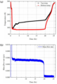
도 18 은 액체질소 주입에 따른 저장탱크 벽면 상/하단부 온도 및 기체질소 유량 측정 결과이다.18 is a result of measuring the temperature of the upper and lower parts of the storage tank wall and the flow rate of gaseous nitrogen according to liquid nitrogen injection.
초기에는 기체질소 및 액체질소를 주입함에 따라 급격하게 온도가 감소 하는 것을 볼 수 있다.In the beginning, it can be seen that the temperature decreases rapidly as gaseous nitrogen and liquid nitrogen are injected.
저장탱크 하단부의 온도는 85 K 근처에서 수렴하였으며, 액체질소의 온도인 77 K 보다 높은데, 실제 E-type Thermo couple 온도센서의 오차 및 벽면 두께에 대한 내/외부 온도 차를 생각하면 어느정도 액체질소 온도에 수렴했다고 판단 할 수 있다.The temperature of the lower part of the storage tank converged around 85 K, which is higher than the liquid nitrogen temperature of 77 K. can be judged to have converged on
외부 열침입에 의해 증발된 기체질소는 열교환기를 통과한 후 유량계를 거쳐 배출되며, 증발량은 약 0.005 g/s (0.25 LPM)으로 유지되었다. 이를 토대로 총 실험시간에 대하여 측정된 유량 데이터를 적분하여 액체질소 주입량을 산출하였다. 액체질소의 주입량은 약 390 g 으로 전체 용량에 대해 약 42 % 정도 충전되었다.Gaseous nitrogen evaporated by external heat penetration passed through the heat exchanger and then discharged through the flowmeter, and the evaporation rate was maintained at about 0.005 g/s (0.25 LPM). Based on this, the liquid nitrogen injection amount was calculated by integrating the flow rate data measured for the total experimental time. The injected amount of liquid nitrogen was about 390 g, and about 42% of the total capacity was filled.
실제 측정된 유량을 토대로 역산하여 외부 열침입을 산출하였다.Based on the actually measured flow rate, inverse calculation was performed to calculate the external heat intrusion.
수학식 8 을 통해 액체수소 저장탱크의 외부 열침입을 산출하면, 액체질 소의 증발잠열이 199 kJ/kg이므로 증발량 0.005 g/s에 대해 약 1 W 의 외부 열침입이 산출된다.When calculating the external heat penetration of the liquid hydrogen storage tank through
이는 앞서 예상했던 전도와 복사 열침입량의 합인 1.8 W 에 비해 45 % 정도의 수준이다. 이는 예상했던 전도 열침입과 복사 열침입에서의 오차라고 판단할 수 있다.This is about 45% of the 1.8 W, which is the sum of conduction and radiation heat penetration, which was previously expected. This can be judged to be an error in the expected conduction heat invasion and radiative heat invasion.
300 K에서 77 K으로의 전도 열침입을 예상했으나, 실제 실험 시에는 액체질소에 의해 SUS tube의 온도가 더 낮을 것이므로 전도 열침입에서 약간의 차이가 발생했을 것으로 예상된다.Conductive heat penetration from 300 K to 77 K was expected, but in the actual experiment, the temperature of the SUS tube would be lower due to liquid nitrogen, so it is expected that a slight difference occurred in the conduction heat penetration.
실험은 약 20시간 동안 진행되었으며, 약 0.005 g/s의 유량이 지속적으로 유지되었다. 저장탱크 수위 90%에 대하여 최대 운전시간을 산출하면, 약 42시간 정도 유지 가능할 것으로 예상된다.The experiment was conducted for about 20 hours, and a flow rate of about 0.005 g/s was continuously maintained. If the maximum operation time is calculated for 90% of the water level of the storage tank, it is expected that it can be maintained for about 42 hours.
1 : 내부탱크
2 : 외부탱크
3 : 공급배관
4 : 배관고정부1: Inner tank
2: External tank
3: supply piping
4: pipe fixing part
Claims (6)
소정의 점도를 가지며, 상기 내부탱크의 외측에 도포되는 제1에폭시접착제;
상기 내부탱크의 외주면으로부터 소정의 거리만큼 이격되도록 3D 프린팅 되는 외부탱크;
상기 제1에폭시접착제와 다른 점도를 가지며, 상기 외부탱크의 외측에 도포되는 제2에폭시접착제; 및
상기 내부탱크의 일측 이상에 연결되는 공급배관;을 포함하고,
상기 내부탱크 및 외부탱크 사이의 공간에는 소정의 진공이 형성되는, 3D 프린팅-에폭시 복합 소재가 적용된 액체수소 저장탱크An inner tank that is 3D printed to withstand a predetermined pressure to store liquid hydrogen;
a first epoxy adhesive having a predetermined viscosity and applied to the outside of the inner tank;
an outer tank 3D printed to be spaced apart from the outer circumferential surface of the inner tank by a predetermined distance;
a second epoxy adhesive having a viscosity different from that of the first epoxy adhesive and applied to the outside of the external tank; and
Including; supply pipe connected to at least one side of the inner tank,
A liquid hydrogen storage tank with a 3D printing-epoxy composite material in which a predetermined vacuum is formed in the space between the inner tank and the outer tank
상기 내부탱크의 저면에 부착되어, 액체수소의 증발량을 조절하도록 내부탱크를 가열시키는 가열부재; 및
상기 가열부재가 내측에 수용되도록 내부탱크의 외측을 감싸도록 구비되는 적층단열재;를 포함하는, 3D 프린팅-에폭시 복합 소재가 적용된 액체수소 저장탱크The method of claim 1,
a heating member attached to the lower surface of the inner tank to heat the inner tank to adjust the amount of evaporation of liquid hydrogen; and
A liquid hydrogen storage tank to which a 3D printing-epoxy composite material is applied, including a laminated insulation material provided to surround the outside of the inner tank so that the heating member is accommodated inside.
상기 내부탱크 및 외부탱크의 벽면은 30% 내지 40% 범위의 Triangular infill 구조로 형성되는, 3D 프린팅-에폭시 복합 소재가 적용된 액체수소 저장탱크The method of claim 1,
The walls of the inner tank and the outer tank are formed with a triangular infill structure in the range of 30% to 40%, a liquid hydrogen storage tank to which a 3D printing-epoxy composite material is applied
상기 내부탱크의 일측 이상에 형성된 통공을 통해, 내부탱크의 내측에 형성된 서포트를 제거하는 단계;
상기 내부탱크의 일측 이상에 형성된 통공에, 배관고정부 및 공급배관을 삽입하는 단계;
상기 내부탱크의 외측 및 배관고정부에 소정의 점도를 가지는 제1에폭시접착제를 도포하는 단계;
상기 제1에폭시접착제를 건조시키는 단계;
상기 내부탱크의 저면에 가열부재를 부착시키는 단계;
상기 내부탱크의 외측을 감싸도록 적층단열재를 8층 이상 적층시키는 단계;
외벽이 30% 내지 40% 범위의 Triangular infill 구조로 형성되도록, 탱크상부 및 탱크하부를 3D 프린터로 출력하는 단계;
상기 탱크상부 및 탱크하부 사이에 내부탱크를 삽입하는 단계;
상기 탱크상부 및 탱크하부의 외주면에 상기 제1에폭시접착제와 다른 점도를 가지는 제2에폭시접착제를 도포하며 탱크상부 및 탱크하부를 접착시켜 외부탱크를 구성하는 단계; 및
상기 제2에폭시접착제를 건조시키는 단계;를 포함하는, 3D 프린팅-에폭시 복합 소재가 적용된 액체수소 저장탱크 제조방법Outputting the inner tank with a 3D printer so that the outer wall is formed with a triangular infill structure ranging from 30% to 40%;
removing a support formed inside the inner tank through a through hole formed on at least one side of the inner tank;
inserting a pipe fixing part and a supply pipe into a through hole formed on at least one side of the inner tank;
applying a first epoxy adhesive having a predetermined viscosity to the outside of the inner tank and to the pipe fixing part;
drying the first epoxy adhesive;
attaching a heating member to the lower surface of the inner tank;
stacking eight or more layers of laminated insulation to surround the outside of the inner tank;
Printing the upper and lower parts of the tank with a 3D printer so that the outer wall is formed in a triangular infill structure ranging from 30% to 40%;
inserting an inner tank between the upper tank and the lower tank;
forming an external tank by applying a second epoxy adhesive having a different viscosity from that of the first epoxy adhesive to outer circumferential surfaces of the upper and lower portions of the tank and adhering the upper and lower portions of the tank; and
Method for manufacturing a liquid hydrogen storage tank to which a 3D printing-epoxy composite material is applied, including drying the second epoxy adhesive
Priority Applications (1)
| Application Number | Priority Date | Filing Date | Title |
|---|---|---|---|
| KR1020210163782A KR102624809B1 (en) | 2021-11-24 | 2021-11-24 | Liquid hydrogen storage tank to which 3D printing-epoxy composite material is applied and its manufacturing method |
Applications Claiming Priority (1)
| Application Number | Priority Date | Filing Date | Title |
|---|---|---|---|
| KR1020210163782A KR102624809B1 (en) | 2021-11-24 | 2021-11-24 | Liquid hydrogen storage tank to which 3D printing-epoxy composite material is applied and its manufacturing method |
Publications (2)
| Publication Number | Publication Date |
|---|---|
| KR20230077035A true KR20230077035A (en) | 2023-06-01 |
| KR102624809B1 KR102624809B1 (en) | 2024-01-15 |
Family
ID=86770625
Family Applications (1)
| Application Number | Title | Priority Date | Filing Date |
|---|---|---|---|
| KR1020210163782A Active KR102624809B1 (en) | 2021-11-24 | 2021-11-24 | Liquid hydrogen storage tank to which 3D printing-epoxy composite material is applied and its manufacturing method |
Country Status (1)
| Country | Link |
|---|---|
| KR (1) | KR102624809B1 (en) |
Cited By (1)
| Publication number | Priority date | Publication date | Assignee | Title |
|---|---|---|---|---|
| CN116906809A (en) * | 2023-06-05 | 2023-10-20 | 成都先进金属材料产业技术研究院股份有限公司 | 3D printing integrated high-pressure hydrogen storage cylinder and preparation method thereof |
Citations (4)
| Publication number | Priority date | Publication date | Assignee | Title |
|---|---|---|---|---|
| JP2018105441A (en) * | 2016-12-27 | 2018-07-05 | 日本ポリエチレン株式会社 | Polyethylene composition for pressure container liner, manufacturing method thereof, and pressure container |
| KR102021038B1 (en) * | 2018-01-15 | 2019-09-11 | 하이리움산업(주) | Storage Tank |
| WO2021034692A1 (en) * | 2019-08-16 | 2021-02-25 | Chart Inc. | Double-walled tank support and method of construction |
| CN113606487A (en) * | 2021-08-24 | 2021-11-05 | 北京化工大学 | V-shaped liner-free high-pressure composite material storage tank molding process |
-
2021
- 2021-11-24 KR KR1020210163782A patent/KR102624809B1/en active Active
Patent Citations (4)
| Publication number | Priority date | Publication date | Assignee | Title |
|---|---|---|---|---|
| JP2018105441A (en) * | 2016-12-27 | 2018-07-05 | 日本ポリエチレン株式会社 | Polyethylene composition for pressure container liner, manufacturing method thereof, and pressure container |
| KR102021038B1 (en) * | 2018-01-15 | 2019-09-11 | 하이리움산업(주) | Storage Tank |
| WO2021034692A1 (en) * | 2019-08-16 | 2021-02-25 | Chart Inc. | Double-walled tank support and method of construction |
| CN113606487A (en) * | 2021-08-24 | 2021-11-05 | 北京化工大学 | V-shaped liner-free high-pressure composite material storage tank molding process |
Cited By (1)
| Publication number | Priority date | Publication date | Assignee | Title |
|---|---|---|---|---|
| CN116906809A (en) * | 2023-06-05 | 2023-10-20 | 成都先进金属材料产业技术研究院股份有限公司 | 3D printing integrated high-pressure hydrogen storage cylinder and preparation method thereof |
Also Published As
| Publication number | Publication date |
|---|---|
| KR102624809B1 (en) | 2024-01-15 |
Similar Documents
| Publication | Publication Date | Title |
|---|---|---|
| Fesmire | Standardization in cryogenic insulation systems testing and performance data | |
| CN102809581B (en) | Device for testing performance of low-temperature vacuum multilayer heat-insulation material based on thermal protection | |
| US10024812B1 (en) | Guarded flat plate cryogenic test apparatus and calorimeter (C-600) | |
| US9488607B2 (en) | Insulation test cryostat with lift mechanism | |
| Stewart et al. | Self-pressurization of a flightweight, liquid hydrogen tank: Simulation and comparison with experiments | |
| Fesmire et al. | Cylindrical boiloff calorimeters for testing of thermal insulation systems | |
| CN108614007A (en) | Multilayer heat-insulating material and composite heat-insulating material performance testing device | |
| Fesmire et al. | Advanced cryogenic insulation systems | |
| KR102624809B1 (en) | Liquid hydrogen storage tank to which 3D printing-epoxy composite material is applied and its manufacturing method | |
| Fesmire et al. | Flat-plate boiloff calorimeters for testing of thermal insulation systems | |
| Darkow et al. | Concept development of a cryogenic tank insulation for reusable launch vehicle | |
| Dewasi et al. | The development of a novel apparatus to measure the emissivity of high-roughness materials at 82 K | |
| KR102565125B1 (en) | Composite materials using 3d printing and their manufacturing methods | |
| Saha et al. | Gas permeability and flexural strength of impacted composites for cryogenic propellant tanks | |
| CN205593952U (en) | Backing material contact interface heat conduction test device in cryrogenic container of vacuum | |
| Wood et al. | Acoustic and thermal testing of an integrated multilayer insulation and broad area cooling shield system | |
| Rhys et al. | Vibro-acoustic test article (VATA) test series | |
| Kyeongho et al. | Composite aerogel insulation for cryogenic liquid storage | |
| Kravchenko et al. | Problem of measuring thermal conductivity of polyurethane thermal insulation of liquid hydrogen tanks for launch vehicle in operational environment | |
| Barrios et al. | AN APPARATUS TO MEASURE THERMAL CONDUCTIVITY OF SPRAY‐ON FOAM INSULATION | |
| Johnson et al. | Cryopumping in cryogenic insulations for a reusable launch vehicle | |
| Zhang et al. | Research on the effect of vacuum on the performance of cryogenic tanks | |
| Saha et al. | Gas Permeability and Flexural Strength Post Impact of Cryogenically Cycled Composites | |
| Saha et al. | Gas permeability of impacted composites for reusable cryogenic fuel tanks | |
| Agrawal et al. | Effect of insulation thickness on evolution of pressure and temperature in a cryogenic tank |
Legal Events
| Date | Code | Title | Description |
|---|---|---|---|
| PA0109 | Patent application |
Patent event code: PA01091R01D Comment text: Patent Application Patent event date: 20211124 |
|
| PA0201 | Request for examination | ||
| PG1501 | Laying open of application | ||
| E902 | Notification of reason for refusal | ||
| PE0902 | Notice of grounds for rejection |
Comment text: Notification of reason for refusal Patent event date: 20230701 Patent event code: PE09021S01D |
|
| E701 | Decision to grant or registration of patent right | ||
| PE0701 | Decision of registration |
Patent event code: PE07011S01D Comment text: Decision to Grant Registration Patent event date: 20231101 |
|
| GRNT | Written decision to grant | ||
| PR0701 | Registration of establishment |
Comment text: Registration of Establishment Patent event date: 20240110 Patent event code: PR07011E01D |
|
| PR1002 | Payment of registration fee |
Payment date: 20240110 End annual number: 3 Start annual number: 1 |
|
| PG1601 | Publication of registration |