KR20230036573A - Wireless Charging Device - Google Patents
Wireless Charging Device Download PDFInfo
- Publication number
- KR20230036573A KR20230036573A KR1020210118256A KR20210118256A KR20230036573A KR 20230036573 A KR20230036573 A KR 20230036573A KR 1020210118256 A KR1020210118256 A KR 1020210118256A KR 20210118256 A KR20210118256 A KR 20210118256A KR 20230036573 A KR20230036573 A KR 20230036573A
- Authority
- KR
- South Korea
- Prior art keywords
- power
- wireless
- power transmission
- coil
- charging
- Prior art date
- Legal status (The legal status is an assumption and is not a legal conclusion. Google has not performed a legal analysis and makes no representation as to the accuracy of the status listed.)
- Ceased
Links
Images


Classifications
-
- H—ELECTRICITY
- H02—GENERATION; CONVERSION OR DISTRIBUTION OF ELECTRIC POWER
- H02J—ELECTRIC POWER NETWORKS; CIRCUIT ARRANGEMENTS OR SYSTEMS FOR SUPPLYING OR DISTRIBUTING ELECTRIC POWER; SYSTEMS FOR STORING ELECTRIC ENERGY
- H02J50/00—Circuit arrangements or systems for wireless supply or distribution of electric power
- H02J50/40—Circuit arrangements or systems for wireless supply or distribution of electric power using two or more transmitting or receiving devices
- H02J50/402—Circuit arrangements or systems for wireless supply or distribution of electric power using two or more transmitting or receiving devices the two or more transmitting or the two or more receiving devices being integrated in the same unit, e.g. power mats with several coils or antennas with several sub-antennas
-
- A—HUMAN NECESSITIES
- A45—HAND OR TRAVELLING ARTICLES
- A45C—PURSES; LUGGAGE; HAND CARRIED BAGS
- A45C11/00—Receptacles for purposes not provided for in groups A45C1/00-A45C9/00
-
- A—HUMAN NECESSITIES
- A45—HAND OR TRAVELLING ARTICLES
- A45C—PURSES; LUGGAGE; HAND CARRIED BAGS
- A45C11/00—Receptacles for purposes not provided for in groups A45C1/00-A45C9/00
- A45C11/001—Receptacles for purposes not provided for in groups A45C1/00-A45C9/00 for storing portable audio devices, e.g. headphones or digital music players
-
- H—ELECTRICITY
- H02—GENERATION; CONVERSION OR DISTRIBUTION OF ELECTRIC POWER
- H02J—ELECTRIC POWER NETWORKS; CIRCUIT ARRANGEMENTS OR SYSTEMS FOR SUPPLYING OR DISTRIBUTING ELECTRIC POWER; SYSTEMS FOR STORING ELECTRIC ENERGY
- H02J50/00—Circuit arrangements or systems for wireless supply or distribution of electric power
- H02J50/005—Mechanical details of housing or structure aiming to accommodate the power transfer means, e.g. mechanical integration of coils, antennas or transducers into emitting or receiving devices
-
- H—ELECTRICITY
- H02—GENERATION; CONVERSION OR DISTRIBUTION OF ELECTRIC POWER
- H02J—ELECTRIC POWER NETWORKS; CIRCUIT ARRANGEMENTS OR SYSTEMS FOR SUPPLYING OR DISTRIBUTING ELECTRIC POWER; SYSTEMS FOR STORING ELECTRIC ENERGY
- H02J50/00—Circuit arrangements or systems for wireless supply or distribution of electric power
- H02J50/10—Circuit arrangements or systems for wireless supply or distribution of electric power using inductive coupling
-
- H—ELECTRICITY
- H02—GENERATION; CONVERSION OR DISTRIBUTION OF ELECTRIC POWER
- H02J—ELECTRIC POWER NETWORKS; CIRCUIT ARRANGEMENTS OR SYSTEMS FOR SUPPLYING OR DISTRIBUTING ELECTRIC POWER; SYSTEMS FOR STORING ELECTRIC ENERGY
- H02J50/00—Circuit arrangements or systems for wireless supply or distribution of electric power
- H02J50/40—Circuit arrangements or systems for wireless supply or distribution of electric power using two or more transmitting or receiving devices
-
- H—ELECTRICITY
- H02—GENERATION; CONVERSION OR DISTRIBUTION OF ELECTRIC POWER
- H02J—ELECTRIC POWER NETWORKS; CIRCUIT ARRANGEMENTS OR SYSTEMS FOR SUPPLYING OR DISTRIBUTING ELECTRIC POWER; SYSTEMS FOR STORING ELECTRIC ENERGY
- H02J7/00—Circuit arrangements for charging or discharging batteries or for supplying loads from batteries
-
- H02J7/0044—
-
- H—ELECTRICITY
- H02—GENERATION; CONVERSION OR DISTRIBUTION OF ELECTRIC POWER
- H02J—ELECTRIC POWER NETWORKS; CIRCUIT ARRANGEMENTS OR SYSTEMS FOR SUPPLYING OR DISTRIBUTING ELECTRIC POWER; SYSTEMS FOR STORING ELECTRIC ENERGY
- H02J7/00—Circuit arrangements for charging or discharging batteries or for supplying loads from batteries
- H02J7/70—Circuit arrangements for charging or discharging batteries or for supplying loads from batteries characterised by the mechanical construction
- H02J7/731—Circuit arrangements for charging or discharging batteries or for supplying loads from batteries characterised by the mechanical construction specially adapted for holding portable devices containing batteries
-
- H—ELECTRICITY
- H04—ELECTRIC COMMUNICATION TECHNIQUE
- H04R—LOUDSPEAKERS, MICROPHONES, GRAMOPHONE PICK-UPS OR LIKE ACOUSTIC ELECTROMECHANICAL TRANSDUCERS; ELECTRIC HEARING AIDS; PUBLIC ADDRESS SYSTEMS
- H04R1/00—Details of transducers, loudspeakers or microphones
- H04R1/10—Earpieces; Attachments therefor ; Earphones; Monophonic headphones
- H04R1/1025—Accumulators specially adapted for earpieces; Arrangements specially adapted for charging thereof
-
- A45C2011/001—
-
- Y—GENERAL TAGGING OF NEW TECHNOLOGICAL DEVELOPMENTS; GENERAL TAGGING OF CROSS-SECTIONAL TECHNOLOGIES SPANNING OVER SEVERAL SECTIONS OF THE IPC; TECHNICAL SUBJECTS COVERED BY FORMER USPC CROSS-REFERENCE ART COLLECTIONS [XRACs] AND DIGESTS
- Y02—TECHNOLOGIES OR APPLICATIONS FOR MITIGATION OR ADAPTATION AGAINST CLIMATE CHANGE
- Y02E—REDUCTION OF GREENHOUSE GAS [GHG] EMISSIONS, RELATED TO ENERGY GENERATION, TRANSMISSION OR DISTRIBUTION
- Y02E60/00—Enabling technologies; Technologies with a potential or indirect contribution to GHG emissions mitigation
- Y02E60/10—Energy storage using batteries
Landscapes
- Engineering & Computer Science (AREA)
- Power Engineering (AREA)
- Computer Networks & Wireless Communication (AREA)
- Physics & Mathematics (AREA)
- Acoustics & Sound (AREA)
- Signal Processing (AREA)
- Charge And Discharge Circuits For Batteries Or The Like (AREA)
Abstract
Description
본 발명은 하나의 전력 송신 코일로 복수개의 무선기기 수신 코일에 충전이 가능한 무선 충전장치에 관한 것이다.The present invention relates to a wireless charging device capable of charging a plurality of wireless device receiving coils with one power transmission coil.
일반적으로 PDA, 휴대전화와 같은 휴대용 전자 기기(또는 휴대용 단말기)에는 외부로부터 전원이 공급되지 않은 상태에서도 전자 기기의 구동에 필요한 전력을 공급하기 위하여, 재사용이 가능한 충전식 배터리(rechargeable battery)를 포함하고 있다.In general, portable electronic devices (or portable terminals) such as PDAs and mobile phones include a reusable rechargeable battery in order to supply power necessary for driving the electronic device even when power is not supplied from the outside. there is.
근래에는 다양한 충전장치가 제공되고 있으며, 충전식 배터리를 충전하기 위한 충전장치로 전원콘센트에 연결하여 사용하는 크래들(cradle)과 같은 고정형 장치와 휴대하며 사용하는 휴대용 충전 장치 등으로 구분할 수 있다.Recently, various charging devices have been provided, and as a charging device for charging a rechargeable battery, it can be divided into a fixed device such as a cradle that is used by connecting to a power outlet and a portable charging device that is carried and used.
이러한 충전 장치가 포함되는 휴대용 전자기기의 대표적인 예로서 무선 이어폰을 들 수 있다. 무선 이어폰은 사용자가 휴대하기에 용이한 형태로 이루어지되 사용자의 귀에 착용하는 형태로 사용되는데, 휴대전화기 및 음향기기 등의 전자기기와 블루투스에 의한 근거리 무선 통신을 수행하여 전자기기로부터의 음성신호를 무선으로 수신하고 이를 재생하여 사용자의 귀에 출력함으로써 음악을 감상하거나 음성 통화할 수 있게 한다.A representative example of a portable electronic device including such a charging device may be a wireless earphone. Wireless earphones are made in a form that is easy for users to carry but are worn in the user's ears. They perform short-range wireless communication with electronic devices such as mobile phones and sound devices by Bluetooth to transmit voice signals from electronic devices. It is received wirelessly, reproduced, and output to the user's ear so that he or she can enjoy music or make a voice call.
이와 같은 무선 이어폰은 근거리 무선 통신을 수행하기 위한 블루투스 모듈을 구비하고 있으며, 해당 블루투스 모듈에 구동 전원을 공급하기 위한 배터리를 구비하고 있다. 이때, 무선 이어폰의 배터리로서는 반복적으로 충전하여 사용 가능하도록 축전지를 사용한다.Such wireless earphones include a Bluetooth module for performing short-range wireless communication, and a battery for supplying driving power to the Bluetooth module. At this time, as the battery of the wireless earphone, a storage battery is used so that it can be repeatedly charged and used.
이에 따라, 무선 이어폰은 내장된 배터리가 방전된 경우 다시 충전시킬 필요가 있으며, 무선 이어폰의 배터리를 충전하기 위하여 전용의 충전장치를 구비하고 있다.Accordingly, the wireless earphone needs to be recharged when the built-in battery is discharged, and a dedicated charging device is provided to charge the battery of the wireless earphone.
이와 같이 이어폰의 배터리를 충전하기 위한 전용의 충전장치로서는, 무선 이어폰의 보관과 함께 무선 이어폰의 배터리를 충전할 수 있는 형태의 충전 케이스가 널리 적용되고 있다. 무선 이어폰을 충전 케이스에 접속시킴으로써 충전 케이스의 직류 전원을 무선 이어폰에 공급하여 무선 이어폰의 배터리를 충전한다.In this way, as a dedicated charging device for charging the battery of the earphone, a charging case capable of charging the battery of the wireless earphone together with storing the wireless earphone is widely applied. By connecting the wireless earphone to the charging case, DC power from the charging case is supplied to the wireless earphone to charge the battery of the wireless earphone.
한편, 무선 이어폰이 유선 이어폰들에 비해 많은 이점들을 가지고 있긴 하지만, 이들은 또한 일부 잠재적 결점들을 갖는다. 예를 들어, 무선 이어폰은 무선 통신 회로 및 디바이스의 다른 컴포넌트들로 전력을 제공하는 재충전가능한 배터리와 같은 하나 이상의 배터리가 필수적으로 요구된다.On the other hand, although wireless earphones have many advantages over wired earphones, they also have some potential drawbacks. For example, wireless earphones necessarily require one or more batteries, such as a rechargeable battery, to provide power to the wireless communication circuitry and other components of the device.
단일 사용 배터리는 자신의 전하가 고갈되면 교환될 필요가 있는 반면, 재충전가능한 배터리는 주기적으로 재충전될 필요가 있다. 또한, 한 쌍의 무선 이어폰은 비교적 작고 비사용시 분실하기 쉽다. 또한, 비교적 작은 무선 이어폰으로부터 고 퀄리티의 음향 성능을 달성하는 것은 각각의 무선 이어폰 내의 이용가능한 공간이 한정적이기 때문에 제조자들에게 부담이 될 수 있다.Single use batteries need to be replaced when their charge is depleted, whereas rechargeable batteries need to be recharged periodically. Also, a pair of wireless earphones are relatively small and easy to lose when not in use. Additionally, achieving high quality sonic performance from relatively small wireless earphones can be a burden for manufacturers because the available space within each wireless earphone is limited.
이러한 무선 이어폰을 비롯한 충전 장치가 포함되는 휴대용 전자기기에는 충전용 전력을 송신하는 전력송신코일과 충전을 위해 전력송신코일이 송신하는 전력을 수신하는 전력수신코일이 포함되는데, 종래에는 이러한 전력송신코일 및 전력수신코일은 1:1로 대응되게 설치되는 것이 일반적이었다. 그러나, 전력송신코일과 전력수신코일을 이용하여 충전을 수행하는 기기에서 항상 전력수신코일의 수만큼 전력송신코일을 구비하는 것은 공간적 측면이나 충전 효율 면에서 바람직하지 않다는 문제가 제기되어 왔다. Portable electronic devices including charging devices such as wireless earphones include a power transmission coil that transmits power for charging and a power reception coil that receives power transmitted by the power transmission coil for charging. Conventionally, such a power transmission coil and power receiving coils are generally installed in a 1:1 correspondence. However, a problem has been raised that it is not desirable in terms of space or charging efficiency to always have as many power transmission coils as there are power reception coils in a device that performs charging using a power transmission coil and a power reception coil.
따라서, 본 발명은 상기와 같은 문제점을 해결하기 위하여 안출된 것으로서, 본 발명의 해결하고자 하는 과제는 하나의 전력송신 코일로 복수개의 무선기기 전력수신 코일에 한번에 충전이 가능한 기능이 구비된 무선 충전장치를 제공하는 것이다.Therefore, the present invention has been made to solve the above problems, and the problem to be solved by the present invention is a wireless charging device having a function that can charge a plurality of wireless device power reception coils at once with one power transmission coil. is to provide
또한, 전력송신기기의 하나의 송신 코일로 한 쌍의 무선 이어폰의 충전이 가능한 기능이 구비된 무선 충전장치를 제공하는 것이다.In addition, to provide a wireless charging device equipped with a function capable of charging a pair of wireless earphones with one transmission coil of a power transmission device.
다만, 본 발명에서 이루고자 하는 기술적 과제들은 이상에서 언급한 기술적 과제들로 제한되지 않으며, 언급하지 않은 또 다른 기술적 과제들은 아래의 기재로부터 본 발명이 속하는 기술분야에서 통상의 지식을 가진 자에게 명확하게 이해될 수 있을 것이다.However, the technical problems to be achieved in the present invention are not limited to the above-mentioned technical problems, and other technical problems not mentioned will be clear to those skilled in the art from the description below. You will be able to understand.
본 발명은 상기와 같은 종래기술의 문제점을 개선하기 위하여 창출된 것으로, 무선으로 충전하는 충전장치로서, 전력을 송신하는 전력송신부; 및 상기 전력송신부를 통해서 전력을 무선으로 수신받는 전력수신부;를 포함하되, 하나의 상기 전력송신부는, 복수개의 상기 전력수신부를 동시에 충전시킬 수 있다.The present invention was created to improve the problems of the prior art as described above, as a charging device for charging wirelessly, a power transmission unit for transmitting power; and a power receiver for wirelessly receiving power through the power transmitter, wherein one power transmitter can simultaneously charge a plurality of power receivers.
또한, 상기 무선 충전장치는 한 쌍의 무선 이어폰을 무선으로 충전하는 충전장치이며, 상기 한 쌍의 무선 이어폰이 수용되어 충전되는 충전케이스; 및 상기 충전케이스와 상기 한 쌍의 무선 이어폰의 각각 대응하는 위치에 설치되어 상기 무선 이어폰을 충전시키는 충전유닛;을 포함하고, 상기 충전유닛은, 상기 전력송신부와 상기 전력수신부를 포함하되, 상기 전력송신부는 상기 충전케이스의 일부분에 설치되어 전력을 송신하고, 상기 전력수신부는 상기 전력송신부에 대응하는 위치에서 상기 무선 이어폰에 구비되어 상기 전력송신부를 통해서 전력을 무선으로 수신받으며, 상기 전력송신부는, 상기 충전케이스의 기설정된 위치에 설치되어 상기 한 쌍의 무선 이어폰에 구비된 각각의 상기 전력수신부를 동시에 충전시킬 수 있다.In addition, the wireless charging device is a charging device for wirelessly charging a pair of wireless earphones, and includes a charging case in which the pair of wireless earphones are accommodated and charged; and a charging unit installed at corresponding positions of the charging case and the pair of wireless earphones to charge the wireless earphones, wherein the charging unit includes the power transmitting unit and the power receiving unit, The transmission unit is installed in a part of the charging case to transmit power, and the power reception unit is provided in the wireless earphone at a position corresponding to the power transmission unit to receive power wirelessly through the power transmission unit. The power transmission unit, It is installed in a predetermined position of the charging case to simultaneously charge each of the power receivers provided in the pair of wireless earphones.
또한, 상기 전력송신부는, 상기 전력수신부에 전력을 송신하는 전력송신코일; 및 상기 전력송신코일에 일체를 이루면서 구비되어 자계를 제공하는 제 1자성체;를 포함할 수 있다.In addition, the power transmission unit may include a power transmission coil for transmitting power to the power reception unit; and a first magnetic body integrally provided with the power transmission coil to provide a magnetic field.
또한, 상기 전력수신부는, 상기 전력송신코일로부터 전력을 송신받는 전력수신코일; 및 상기 전력수신코일에 일체를 이루면서 구비되어 자계를 제공하며, 상기 제 1자성체에 대응하는 제 2자성체;를 포함할 수 있다.In addition, the power receiving unit may include a power receiving coil receiving power transmitted from the power transmitting coil; and a second magnetic body provided integrally with the power receiving coil to provide a magnetic field and corresponding to the first magnetic body.
또한, 상기 제 1, 2자성체는 상기 전력송신코일과 전력수신코일의 중앙을 관통하며 서로 대응하는 위치에 각각 구비될 수 있다.In addition, the first and second magnetic materials may be provided at positions corresponding to each other while penetrating the center of the power transmission coil and the power reception coil.
또한, 상기 전력송신코일의 직경이 상기 전력수신코일의 직경보다 크게 제작될 수 있다.In addition, the diameter of the power transmission coil may be made larger than the diameter of the power reception coil.
또한, 상기 전력송신코일의 직경과 상기 전력수신코일의 직경 크기가 동일하게 제작될 수 있다.Also, the power transmission coil may have the same diameter as the power reception coil.
또한 상기 전력송신코일의 직경이 상기 전력수신코일의 직경보다 작게 제작될 수 있다.In addition, the diameter of the power transmission coil may be made smaller than the diameter of the power reception coil.
또한, 상기 전력송신코일은 상기 충전케이스의 중앙 부분에 설치되며 상기 전력송신코일을 사이에 두고, 상기 한 쌍의 전력수신코일이 상기 충전케이스 내에서 각각 대칭하는 형상으로 배치될 수 있다.In addition, the power transmission coil is installed in the central portion of the charging case, the power transmission coil is interposed therebetween, and the pair of power reception coils may be disposed in a symmetrical shape within the charging case.
본 발명의 일실시예에 따르면, 하나의 전력송신부로 복수의 전력수신부를 동시에 충전시키므로 각각의 무선기기의 충전에 소요되는 시간 및 별도의 전력송신부의 사용이 필요없으므로 비용의 절감이 가능하다.According to an embodiment of the present invention, since a plurality of power receivers are simultaneously charged by a single power transmitter, costs can be reduced because the time required for charging each wireless device and the use of a separate power transmitter are not required.
또한, 충전케이스에 설치되는 하나의 전력송신부를 통해서 한쌍의 무선 이어폰에 구비된 전력수신부에 각각 무선으로 충전이 가능하여 충전케이스의 효율적인 공간 활용이 가능하여 제품을 소형화 할 수 있다.In addition, each power receiver provided in a pair of wireless earphones can be wirelessly charged through one power transmitter installed in the charging case, so that efficient use of space in the charging case is possible and the product can be miniaturized.
다만, 본 발명에서 얻을 수 있는 효과는 이상에서 언급한 효과들로 제한되지 않으며, 언급하지 않은 또 다른 효과들은 아래의 기재로부터 본 발명이 속하는 기술분야에서 통상의 지식을 가진 자에게 명확하게 이해될 수 있을 것이다.However, the effects obtainable in the present invention are not limited to the effects mentioned above, and other effects not mentioned will be clearly understood by those skilled in the art from the description below. You will be able to.
본 명세서에서 첨부되는 다음의 도면들은 본 발명의 바람직한 실시예를 예시하는 것이며, 후술하는 발명의 상세한 설명과 함께 본 발명의 기술사상을 더욱 이해시키는 역할을 하는 것이므로, 본 발명은 그러한 도면에 기재된 사항에만 한정되어서 해석되어서는 아니된다.
도 1은 본 발명의 일실시예에 따른 무선 충전장치 장치의 사시도이다.
도 2는 상기 충전유닛의 세부상세도이다.
도 3은 상기 충전유닛의 제 2세부상세도이다.
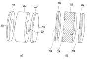
도 4는 상기 충전유닛의 제 1실시예(a)와 그 단면도(b)이다.
도 5는 상기 충전유닛의 제 2실시예(a)와 그 단면도(b)이다.
도 6은 상기 무선 충전장치의 구성요소의 제어블록도이다.The following drawings attached to this specification illustrate preferred embodiments of the present invention, and together with the detailed description of the present invention serve to further understand the technical idea of the present invention, the present invention is the details described in such drawings should not be construed as limited to
1 is a perspective view of a wireless charging device according to an embodiment of the present invention.
2 is a detailed view of the charging unit.
3 is a second detailed view of the charging unit.
4 is a first embodiment (a) of the charging unit and a sectional view (b) thereof.
5 is a second embodiment (a) of the charging unit and a cross-sectional view (b) thereof.
6 is a control block diagram of components of the wireless charging device.
아래에서는 첨부한 도면을 참고로 하여 본 발명의 실시 예에 대하여 본 발명이 속하는 기술분야에서 통상의 지식을 가진 자가 용이하게 실시할 수 있도록 상세히 설명한다. 그러나 본 발명에 관한 설명은 구조적 내지 기능적 설명을 위한 실시 예에 불과하므로, 본 발명의 권리범위는 본문에 설명된 실시 예에 의하여 제한되는 것으로 해석되어서는 아니 된다. 즉, 실시 예는 다양한 변경이 가능하고 여러 가지 형태를 가질 수 있으므로 본 발명의 권리범위는 기술적 사상을 실현할 수 있는 균등물들을 포함하는 것으로 이해되어야 한다. 또한, 본 발명에서 제시된 목적 또는 효과는 특정 실시예가 이를 전부 포함하여야 한다거나 그러한 효과만을 포함하여야 한다는 의미는 아니므로, 본 발명의 권리범위는 이에 의하여 제한되는 것으로 이해되어서는 아니 될 것이다.Hereinafter, with reference to the accompanying drawings, embodiments of the present invention will be described in detail so that those skilled in the art can easily carry out the present invention. However, since the description of the present invention is only an embodiment for structural or functional description, the scope of the present invention should not be construed as being limited by the embodiments described in the text. That is, since the embodiment can be changed in various ways and can have various forms, it should be understood that the scope of the present invention includes equivalents capable of realizing the technical idea. In addition, since the object or effect presented in the present invention does not mean that a specific embodiment should include all of them or only such effects, the scope of the present invention should not be construed as being limited thereto.
본 발명에서 서술되는 용어의 의미는 다음과 같이 이해되어야 할 것이다.The meaning of terms described in the present invention should be understood as follows.
"제1", "제2" 등의 용어는 하나의 구성요소를 다른 구성요소로부터 구별하기 위한 것으로, 이들 용어들에 의해 권리범위가 한정되어서는 아니 된다. 예를 들어, 제1 구성요소는 제2 구성요소로 명명될 수 있고, 유사하게 제2 구성요소도 제1 구성요소로 명명될 수 있다. 어떤 구성요소가 다른 구성요소에 "연결되어" 있다고 언급된 때에는, 그 다른 구성요소에 직접적으로 연결될 수도 있지만, 중간에 다른 구성요소가 존재할 수도 있다고 이해되어야 할 것이다. 반면에, 어떤 구성요소가 다른 구성요소에 "직접 연결되어" 있다고 언급된 때에는 중간에 다른 구성요소가 존재하지 않는 것으로 이해되어야 할 것이다. 한편, 구성요소들 간의 관계를 설명하는 다른 표현들, 즉 "~사이에"와 "바로 ~사이에" 또는 "~에 이웃하는"과 "~에 직접 이웃하는" 등도 마찬가지로 해석되어야 한다.Terms such as "first" and "second" are used to distinguish one component from another, and the scope of rights should not be limited by these terms. For example, a first element may be termed a second element, and similarly, a second element may be termed a first element. It should be understood that when an element is referred to as “connected” to another element, it may be directly connected to the other element, but other elements may exist in the middle. On the other hand, when an element is referred to as being “directly connected” to another element, it should be understood that no intervening elements exist. Meanwhile, other expressions describing the relationship between components, such as “between” and “immediately between” or “adjacent to” and “directly adjacent to” should be interpreted similarly.
단수의 표현은 문맥상 명백하게 다르게 뜻하지 않는 한 복수의 표현을 포함하는 것으로 이해되어야 하고, "포함하다" 또는 "가지다" 등의 용어는 설시된 특징, 숫자, 단계, 동작, 구성요소, 부분품 또는 이들을 조합한 것이 존재함을 지정하려는 것이며, 하나 또는 그 이상의 다른 특징이나 숫자, 단계, 동작, 구성요소, 부분품 또는 이들을 조합한 것들의 존재 또는 부가 가능성을 미리 배제하지 않는 것으로 이해되어야 한다.Singular expressions should be understood to include plural expressions unless the context clearly dictates otherwise, and terms such as “comprise” or “having” refer to a described feature, number, step, operation, component, part, or It should be understood that it is intended to indicate that a combination exists, and does not preclude the possibility of the presence or addition of one or more other features, numbers, steps, operations, components, parts, or combinations thereof.
여기서 사용되는 모든 용어들은 다르게 정의되지 않는 한, 본 발명이 속하는 분야에서 통상의 지식을 가진 자에 의해 일반적으로 이해되는 것과 동일한 의미를 가진다. 일반적으로 사용되는 사전에 정의되어 있는 용어들은 관련 기술의 문맥상 가지는 의미와 일치하는 것으로 해석되어야 하며, 본 발명에서 명백하게 정의하지 않는 한 이상적이거나 과도하게 형식적인 의미를 지니는 것으로 해석될 수 없다.All terms used herein have the same meaning as commonly understood by one of ordinary skill in the art to which the present invention belongs, unless defined otherwise. Terms defined in commonly used dictionaries should be interpreted as consistent with meanings in the context of related art, and cannot be interpreted as having ideal or excessively formal meanings unless explicitly defined in the present invention.
도 1은 본 발명의 일실시예에 따른 무선 충전장치 장치의 사시도이고, 도 2는 상기 충전유닛의 세부상세도이며, 도 3은 상기 충전유닛의 제 2세부상세도이고, 도 4는 상기 충전유닛의 제 1실시예(a)와 그 단면도(b)이며, 도 5는 상기 충전유닛의 제 2실시예(a)와 그 단면도(b)이고, 도 6은 상기 이어폰 무선 충전장치의 구성요소의 제어블록도이다.1 is a perspective view of a wireless charging device according to an embodiment of the present invention, FIG. 2 is a detailed view of the charging unit, FIG. 3 is a second detailed view of the charging unit, and FIG. 4 is the charging unit. A first embodiment of the unit (a) and its cross-sectional view (b), Figure 5 is a second embodiment of the charging unit (a) and its cross-sectional view (b), Figure 6 is the component of the earphone wireless charging device It is a control block diagram of
도 1 내지 도 6에 도시된 바와 같이, 본 발명의 일 실시예에 따른 무선 충전장치(10)는 전력송신부(210) 및 전력수신부(220)를 포함할 수 있다.As shown in FIGS. 1 to 6 , the
전력송신부(210)는 전력수신부(220)로 전력을 송신할 수 있다.The
전력수신부(220)는 전력송신부(210)를 통해서 전력을 무선으로 수신받을 수 있다.The
하나의 전력송신부(210)는 복수개의 전력수신부(220)를 동시에 충전시킬 수 있다.One
구체적으로, 무선 충전장치(10)는 충전코일 및 후술할 제어부(300) 등으로 구성될 수 있다. 충전코일은 전력송신부(210)와 전력수신부(220)에 각각 구비된다.Specifically, the
본 발명의 일 실시예에 따른 무선 충전장치(10)는 한 쌍의 무선 이어폰(30)을 무선으로 충전하는 충전장치이며, 충전케이스(100) 및 충전유닛(200)을 포함할 수 있다.The
충전케이스(100)는 한 쌍의 무선 이어폰(30)이 수용되어 충전될 수 있다.The charging
충전유닛(200)은 충전케이스(100)와 한 쌍의 무선 이어폰(30)의 각각 대응하는 위치에 설치되어 무선 이어폰(30)을 충전시킬 수 있다.The charging
한편, 무선 전력 전송은 하나 이상의 무선 전력 전달 방법을 이용하여 충전케이스(100)에서 무선 이어폰(30)으로 상호간 접촉 없이 무선으로 전력을 전달할 수 있다. 즉, 무선 전력 신호에 의한 전자기 유도 현상에 기초한 유도 결합(Inductive Coupling) 방식과 특정한 주파수의 무선 전력 신호에 의한 전자기적 공진 현상에 기초한 공진 결합(Electromagnetic Resonance Coupling) 방식 중 하나 이상을 이용하여 전력을 전달할 수 있다.On the other hand, wireless power transmission can wirelessly transfer power from the charging
유도 결합 방식에 의한 무선 전력 송신은 1차 코일 및 2차 코일을 이용하여 전력을 무선으로 전송하는 기술로, 전자기 유도 현상에 의하여 하나의 코일에서 변화하는 자기장을 통해 다른 코일 쪽에 전류가 유도됨으로써 전력이 전달되는 것을 말한다.Wireless power transmission by inductive coupling is a technology that wirelessly transmits power using a primary coil and a secondary coil, and a current is induced toward the other coil through a magnetic field that changes in one coil by electromagnetic induction. that is conveyed
공진 결합 방식에 의한 무선 전력 송신은 전송한 무선 전력 신호에 의하여 충전케이스(100)에서 공진이 발생하고, 공진 현상에 의하여 무선 이어폰(30)으로 전력이 전달되는 것을 말한다.The wireless power transmission by the resonance coupling method means that resonance occurs in the charging
충전유닛(200)은 전력송신부(210) 및 전력수신부(220)를 포함할 수 있다.The charging
전력송신부(210)는 충전케이스(100)의 일부분에 설치되어 전력을 송신할 수있다. 구체적으로, 전력송신부(210)는 제어부(300)의 제어에 의해 충전케이스(100) 내부에 구비되어 외부에서 제공되는 전원이나 전력이 저장되는 배터리로부터 충전된 전력을 송신할 수 있다.The
전력송신부(210)는 전력송신코일(212) 및 제 1자성체(214)를 포함할 수 있다. 전력송신코일(212)은 전력수신부(220)에 전력을 송신할 수 있다. 제 1자성체(214)는 전력송신코일(212)에 일체를 이루면서 구비되어 자계를 제공할 수 있다.The
전력수신부(220)는 전력송신부(210)에 대응하는 위치에서 무선 이어폰(30)에 구비되어 전력송신부(210)를 통해서 전력을 무선으로 수신받을 수 있다.The
전력수신부(220)는 전력수신코일(222) 및 제 2자성체(224)를 포함할 수 있다. 전력수신코일(222)은 전력송신코일(212)로부터 전력을 송신받을 수 있다. 제 2자성체(224)는 제 1자성체(214)에 대응하여 전력수신코일(222)에 일체를 이루면서 구비되어 자계를 제공할 수 있다.The
또한, 전력 변환부는 공진 결합 방식에 따라 무선 이어폰(30)에 공진 현상을 발생시키기 위하여 특정 공진 주파수를 가진 전자기장을 형성시키는 코일(또는 안테나)를 포함하도록 구성될 수 있으며, 이때 본 발명의 일 실시예에 따른 전력송신코일(212)이 공진 현상을 발생시키기 위하여 특정 공진 주파수를 가진 전자기장을 형성시키는 코일(또는 안테나)일 수 있다.In addition, the power conversion unit may be configured to include a coil (or antenna) that forms an electromagnetic field having a specific resonance frequency in order to generate a resonance phenomenon in the
또한, 전력 변환부는 전술된 유도 결합 방식과 공진 결합 방식 중 하나 이상의 방법을 이용하여 전력을 전달할 수 있고, 무선 전력 신호를 형성시키기 위해 사용되는 주파수, 인가되는 전압, 전류 등의 특성을 조절할 수 있는 회로를 더 포함하도록 구성될 수 있다.In addition, the power conversion unit may transmit power using one or more of the above-described inductive coupling method and resonant coupling method, and may adjust characteristics such as frequency, applied voltage, and current used to form a wireless power signal. It may be configured to further include a circuit.
전력송신부(210)는 충전케이스(100)의 기 설정된 위치에 설치되어 한 쌍의 무선 이어폰(30)에 구비된 각각의 전력수신부(220)를 동시에 충전시킬 수 있다. 전력송신코일(212)은 예를 들면, 한 쌍의 전력수신부(220)의 중앙 부분에 설치되며 전력송신코일(212)을 사이에 두고, 한 쌍의 전력수신코일(222)이 충전케이스(100) 내에서 각각 대칭하는 형상으로 배치될 수 있다.The
구체적으로, 전력송신부(210)를 충전케이스(100)의 일부분인 중앙부 등에 하나만 설치하고, 전력송신부(210)를 사이에 두고 한 쌍의 무선 이어폰(30) 충전이 가능하므로 공간을 보다 효율적으로 사용할 수 있다. 또한, 전력송신부(210)를 하나만 설치할 수 있어 휴대성의 향상을 위한 기기의 소형화 등 보다 다양한 형상의 충전케이스(100)의 제작도 가능하다.Specifically, since only one
본 발명의 제 1, 2자성체(214, 224)는 전력송신코일(212)과 전력수신코일(222)의 중앙을 관통하며 서로 대응하는 위치에 각각 구비될 수 있다.The first and second
도 6은 상기 무선 충전장치의 구성요소의 제어블록도이다. 도 6을 더 참고하면, 본 발명의 일 실시예에 따른 무선 충전장치는, 본 발명의 충전케이스(100)의 일부분에 구비되며 충전유닛(200)에 연결되어 충전유닛(200)의 작동을 제어하는 제어부(300)를 더 포함할 수 있다.6 is a control block diagram of components of the wireless charging device. 6, the wireless charging device according to an embodiment of the present invention is provided in a portion of the charging
구체적으로, 제어부(300)는 무선 충전장치(10)나 충전케이스(100)의 일부분에 설치되고, 무선 통신모듈이 구비되어 외부의 모바일 기기 등과 와이파이 통신모듈, 블루트스 통신모듈 및 지그비 통신모듈 중에서 어느 하나로 연동되어 외부에서도 작동을 제어하거나 제어 상황을 실시간으로 확인할 수 있다.Specifically, the
도 3은 상기 충전유닛의 제 2세부상세도이다, 도 3을 더 참고하면, 본 발명의 무선 충전장치(10)는 전력송신코일(212)의 직경이 전력수신코일(222)의 직경 보다 크게 제작될 수 있다. 또한, 본 발명의 무선 충전장치(10)는 전력송신코일(212)의 직경과 전력수신코일(222)의 직경 크기가 동일하게 제작될 수 있다. 한편, 도면에는 표시되지 않았지만, 본 발명의 무선 충전장치(10)는 전력송신코일(212)의 직경이 전력수신코일(222)의 직경 보다 작게도 제작될 수 있다.3 is a second detailed view of the charging unit. Referring further to FIG. 3, in the
구체적으로, 전력송신코일(212)의 일면을 이에 대응하는 전력수신코일(222)의 일면 보다 크게 또는 작게하거나 전력송신코일(212)의 일면과 이에 대응하는 전력수신코일(222)의 일면 크기를 동일하게 제작하여 환경이나 상황에 따라 적절한 크기를 채택하여 무선 이어폰(30)과 충전케이스(100) 공간의 효율적인 사용이 가능하다.Specifically, one side of the
도 4는 상기 충전유닛의 제 1실시예(a)와 그 단면도(b)이며, 도 5는 상기 충전유닛의 제 2실시예(a)와 그 단면도(b)이다. 도 4와 도 5를 더욱 참고하면, 본 발명의 무선 충전장치(10)는 전력송신부(210)의 단면 두께가 설정된 크기로 제작될 수 있다. 구체적으로, 전력송신부(210)의 전력송신코일(212) 단면의 두께를 다양하게 제작하여 사용환경이나 충전용량에 따라서 적절하게 채택하여 사용할 수 있다.4 is a first embodiment (a) of the charging unit and its cross-sectional view (b), and FIG. 5 is a second embodiment (a) and its cross-sectional view (b) of the charging unit. Further referring to FIGS. 4 and 5 , the
또한, 제 1자성체(214)와 제 2자성체(224)의 직경 크기와 두께를 설정된 크기와 두께로 다양하게 제작이 가능하며, 사용되는 무선 충전기기들에 따라 적절하게 변형되어 제작될 수 있다.In addition, the diameter size and thickness of the first
본 발명의 무선 충전장치(10)의 제 2자성체(224)는 전력수신코일(222)의 중앙부를 관통하며 설치되거나 전력수신코일(222)의 일면에 대응하는 형상으로 제작되어 전력수신코일(222)의 외측 일면에 밀착하여 받쳐주면서 일부분은 전력수신코일(222)의 중앙부를 관통하는 형상으로 설치되어 보다 강력한 자계를 제공할 수 있다.The second
따라서, 본 발명의 일실시예 따른 무선 충전장치(10)는 전술한 무선 이어폰(30)을 비롯하여, 태블릿, 노트북, 휴대전화 뿐만 아니라 무선 충전의 적용이 가능한 다양한 전자기기들에 적용하여 사용이 가능하다.Therefore, the
본 발명의 일실시예에 따르면, 하나의 전력송신부(210)로 복수의 전력수신부(220)를 동시에 충전시키므로 각각의 무선기기의 충전에 소요되는 시간 및 별도의 전력송신부(210)의 사용이 필요없으므로 비용의 절감이 가능하다.According to one embodiment of the present invention, since a plurality of
또한, 충전케이스(100)에 설치되는 하나의 전력송신부(210)를 통해서 한쌍의 무선 이어폰(30)에 구비된 전력수신부(220)에 각각 무선으로 충전이 가능하여 충전케이스(100)의 효율적인 공간 활용이 가능하다.In addition, each
상술한 바와 같이 개시된 본 발명의 바람직한 실시예들에 대한 상세한 설명은 당업자가 본 발명을 구현하고 실시할 수 있도록 제공되었다. 상기에서는 본 발명의 바람직한 실시 예들을 참조하여 설명하였지만, 해당 기술 분야의 숙련된 당업자는 본 발명의 영역으로부터 벗어나지 않는 범위 내에서 본 발명을 다양하게 수정 및 변경시킬 수 있음을 이해할 수 있을 것이다. 예를 들어, 당업자는 상술한 실시 예들에 기재된 각 구성을 서로 조합하는 방식으로 이용할 수 있다. 따라서, 본 발명은 여기에 나타난 실시형태들에 제한되려는 것이 아니라, 여기서 개시된 원리들 및 신규한 특징들과 일치하는 최광의 범위를 부여하려는 것이다.Detailed descriptions of the preferred embodiments of the present invention disclosed as described above are provided to enable those skilled in the art to implement and practice the present invention. Although the above has been described with reference to preferred embodiments of the present invention, those skilled in the art will understand that the present invention can be variously modified and changed without departing from the scope of the present invention. For example, those skilled in the art may use each configuration described in the above-described embodiments in a way of combining each other. Thus, the present invention is not intended to be limited to the embodiments shown herein but is to be accorded the widest scope consistent with the principles and novel features disclosed herein.
본 발명은 본 발명의 정신 및 필수적 특징을 벗어나지 않는 범위에서 다른 특정한 형태로 구체화될 수 있다. 따라서, 상기의 상세한 설명은 모든 면에서 제한적으로 해석되어서는 아니 되고 예시적인 것으로 고려되어야 한다. 본 발명의 범위는 첨부된 청구항의 합리적 해석에 의해 결정되어야 하고, 본 발명의 등가적 범위 내에서의 모든 변경은 본 발명의 범위에 포함된다. 본 발명은 여기에 나타난 실시형태들에 제한되려는 것이 아니라, 여기서 개시된 원리들 및 신규한 특징들과 일치하는 최광의 범위를 부여하려는 것이다. 또한, 특허청구범위에서 명시적인 인용 관계가 있지 않은 청구항들을 결합하여 실시 예를 구성하거나 출원 후의 보정에 의해 새로운 청구항으로 포함할 수 있다.The present invention may be embodied in other specific forms without departing from the spirit and essential characteristics of the present invention. Accordingly, the above detailed description should not be construed as limiting in all respects and should be considered as illustrative. The scope of the present invention should be determined by reasonable interpretation of the appended claims, and all changes within the equivalent scope of the present invention are included in the scope of the present invention. The invention is not intended to be limited to the embodiments shown herein but is to be accorded the widest scope consistent with the principles and novel features disclosed herein. In addition, claims that do not have an explicit citation relationship in the claims may be combined to form an embodiment or may be included as new claims by amendment after filing.
10 : 무선 충전장치
30 : 무선 이어폰
100 : 충전케이스
200 : 충전유닛
210 : 전력송신부
212 : 전력송신코일
214 : 제 1자성체
220 : 전력수신부
222 : 전력수신코일
224 : 제 2자성체
300 : 제어부10: wireless charging device
30: wireless earphone
100: charging case
200: charging unit
210: power transmission unit
212: power transmission coil
214: first magnetic body
220: power receiving unit
222: power receiving coil
224: second magnetic body
300: control unit
Claims (9)
전력을 송신하는 전력송신부; 및
상기 전력송신부를 통해서 전력을 무선으로 수신받는 전력수신부;를 포함하되,
하나의 상기 전력송신부는, 복수개의 상기 전력수신부를 동시에 충전시키는 것을 특징으로 하는 무선 충전장치.
As a wireless charging device,
a power transmission unit that transmits power; and
A power receiving unit for receiving power wirelessly through the power transmitting unit; including,
The wireless charging device, characterized in that one of the power transmitting unit simultaneously charges a plurality of the power receiving unit.
상기 무선 충전장치는 한 쌍의 무선 이어폰을 무선으로 충전하는 충전장치이며,
상기 한 쌍의 무선 이어폰이 수용되어 충전되는 충전케이스; 및
상기 충전케이스와 상기 한 쌍의 무선 이어폰의 각각 대응하는 위치에 설치되어 상기 무선 이어폰을 충전시키는 충전유닛;을 포함하고,
상기 충전유닛은,
상기 전력송신부와 상기 전력수신부를 포함하되,
상기 전력송신부는 상기 충전케이스의 일부분에 설치되어 전력을 송신하고,
상기 전력수신부는 상기 전력송신부에 대응하는 위치에서 상기 무선 이어폰에 구비되어 상기 전력송신부를 통해서 전력을 무선으로 수신받으며,
상기 전력송신부는,
상기 충전케이스의 기설정된 위치에 설치되어 상기 한 쌍의 무선 이어폰에 구비된 각각의 상기 전력수신부를 동시에 충전시키는 것을 특징으로 하는 무선 충전장치.
The method of claim 1,
The wireless charging device is a charging device for wirelessly charging a pair of wireless earphones,
a charging case in which the pair of wireless earphones are accommodated and charged; and
A charging unit installed at corresponding positions of the charging case and the pair of wireless earphones to charge the wireless earphones;
The charging unit,
Including the power transmitter and the power receiver,
The power transmission unit is installed in a portion of the charging case to transmit power,
The power receiving unit is provided in the wireless earphone at a position corresponding to the power transmitting unit to wirelessly receive power through the power transmitting unit,
The power transmission unit,
The wireless charging device, characterized in that installed in a predetermined position of the charging case to simultaneously charge each of the power receivers provided in the pair of wireless earphones.
상기 전력송신부는,
상기 전력수신부에 전력을 송신하는 전력송신코일; 및
상기 전력송신코일에 일체를 이루면서 구비되어 자계를 제공하는 제 1자성체;를 포함하는 것을 특징으로 하는 무선 충전장치.
The method of claim 1,
The power transmission unit,
a power transmission coil that transmits power to the power receiver; and
A wireless charging device comprising a; first magnetic body provided integrally with the power transmission coil to provide a magnetic field.
상기 전력수신부는,
상기 전력송신코일로부터 전력을 송신받는 전력수신코일; 및
상기 전력수신코일에 일체를 이루면서 구비되어 자계를 제공하며, 상기 제 1자성체에 대응하는 제 2자성체;를 포함하는 것을 특징으로 하는 무선 충전장치.
The method of claim 3,
The power receiver,
a power reception coil receiving power transmitted from the power transmission coil; and
A wireless charging device comprising a second magnetic body provided integrally with the power receiving coil to provide a magnetic field and corresponding to the first magnetic body.
상기 제 1, 2자성체는 상기 전력송신코일과 전력수신코일의 중앙을 관통하며 서로 대응하는 위치에 각각 구비되는 것을 특징으로 하는 무선 충전장치.
The method of claim 4,
The first and second magnetic materials penetrate through the center of the power transmission coil and the power reception coil and are respectively provided at positions corresponding to each other.
상기 전력송신코일의 직경이 상기 전력수신코일의 직경 보다 크게 제작되는 무선 충전장치.
The method of claim 4,
A wireless charging device in which the diameter of the power transmission coil is made larger than the diameter of the power reception coil.
상기 전력송신코일의 직경과 상기 전력수신코일의 직경 크기가 동일하게 제작되는 이어폰 무선 충전장치.
The method of claim 4,
Earphone wireless charging device in which the diameter of the power transmission coil and the diameter size of the power reception coil are made the same.
상기 전력송신코일의 직경이 상기 전력수신코일의 직경 보다 작게 제작되는 무선 충전장치.
The method of claim 4,
A wireless charging device in which the diameter of the power transmission coil is made smaller than the diameter of the power reception coil.
상기 전력송신코일은 상기 충전케이스에 설치되며 상기 전력송신코일을 사이에 두고, 상기 한 쌍의 전력수신코일이 상기 충전케이스 내에서 각각 대칭하는 형상으로 배치되는 것을 특징으로 하는 이어폰 무선 충전장치.According to claim 2 or 4,
The power transmission coil is installed in the charging case, and the power transmission coil is interposed therebetween, and the pair of power reception coils are disposed in a symmetrical shape within the charging case.
Priority Applications (2)
| Application Number | Priority Date | Filing Date | Title |
|---|---|---|---|
| KR1020210118256A KR20230036573A (en) | 2021-09-06 | 2021-09-06 | Wireless Charging Device |
| PCT/KR2022/013330 WO2023033625A1 (en) | 2021-09-06 | 2022-09-06 | Wireless charging device |
Applications Claiming Priority (1)
| Application Number | Priority Date | Filing Date | Title |
|---|---|---|---|
| KR1020210118256A KR20230036573A (en) | 2021-09-06 | 2021-09-06 | Wireless Charging Device |
Publications (1)
| Publication Number | Publication Date |
|---|---|
| KR20230036573A true KR20230036573A (en) | 2023-03-15 |
Family
ID=85411505
Family Applications (1)
| Application Number | Title | Priority Date | Filing Date |
|---|---|---|---|
| KR1020210118256A Ceased KR20230036573A (en) | 2021-09-06 | 2021-09-06 | Wireless Charging Device |
Country Status (2)
| Country | Link |
|---|---|
| KR (1) | KR20230036573A (en) |
| WO (1) | WO2023033625A1 (en) |
Citations (1)
| Publication number | Priority date | Publication date | Assignee | Title |
|---|---|---|---|---|
| KR102081030B1 (en) | 2015-09-30 | 2020-02-24 | 애플 인크. | Wireless listening device and case |
Family Cites Families (4)
| Publication number | Priority date | Publication date | Assignee | Title |
|---|---|---|---|---|
| KR102087138B1 (en) * | 2012-05-14 | 2020-03-10 | 엘지전자 주식회사 | Wireless power transmitting apparatus |
| US9854344B2 (en) * | 2016-01-03 | 2017-12-26 | Braven, Lc | Wireless earphones and earphones charging case |
| KR200489142Y1 (en) * | 2018-07-30 | 2019-05-09 | (주)에이치에스더컴퍼니 | Auxiliary battery equipped with wireless charging module |
| EP4447267A3 (en) * | 2019-03-25 | 2025-06-18 | LG Electronics Inc. | Method and apparatus for performing power calibration in wireless power transfer system |
-
2021
- 2021-09-06 KR KR1020210118256A patent/KR20230036573A/en not_active Ceased
-
2022
- 2022-09-06 WO PCT/KR2022/013330 patent/WO2023033625A1/en not_active Ceased
Patent Citations (1)
| Publication number | Priority date | Publication date | Assignee | Title |
|---|---|---|---|---|
| KR102081030B1 (en) | 2015-09-30 | 2020-02-24 | 애플 인크. | Wireless listening device and case |
Also Published As
| Publication number | Publication date |
|---|---|
| WO2023033625A1 (en) | 2023-03-09 |
Similar Documents
| Publication | Publication Date | Title |
|---|---|---|
| EP3493556B1 (en) | All-in-one method for wireless connectivity and contactless battery charging of small wearables | |
| JP6339248B2 (en) | Charging system and electronic device including the same | |
| US7627289B2 (en) | Wireless stereo headset | |
| CN102318161B (en) | For the wireless power transmission of portable enclosure | |
| KR101685694B1 (en) | Wireless power utilization in a local computing environment | |
| US11700472B1 (en) | Wireless charging with master-slave receivers | |
| US20200007971A1 (en) | Headset capable of wireless charging, and headset charging system using wireless power transmission comprising same | |
| US11564420B2 (en) | Wearable apparatus for wired or wireless charging of an electronic device | |
| KR20160127056A (en) | Power source device for portable apparatus, portable apparatus, and charging device | |
| KR20140091362A (en) | Wireless charge battery modul for common installing NFC antena and recive coil on battery | |
| US20120181855A1 (en) | Devices and systems supporting contactless charging of bluetooth headsets and other wireless headsets | |
| CN109905798A (en) | Wireless headset | |
| KR102149528B1 (en) | Multi-function wireless charging device | |
| US11838714B1 (en) | Parallel wireless charging for electronic devices | |
| CN104685761A (en) | Wireless power transmission device and method for controlling power supply for wireless power transmission device | |
| CN105284031A (en) | Electricity supply module using wireless power transmission and power supply method of electricity supply module | |
| KR20140034371A (en) | Exterior case of mobile phone for wireless charging using electromagnetic coupled resonance method | |
| KR20230036573A (en) | Wireless Charging Device | |
| KR102406837B1 (en) | Wireless headphone having flexible battery | |
| CN204013677U (en) | Wireless charging electric discharge Cellphone Accessories | |
| WO2024007651A1 (en) | Stylus and electronic device assembly | |
| KR102449497B1 (en) | Wireless Earphones and Charging Case with Antenna for Charging and Communication | |
| CN223472318U (en) | One-to-four wireless microphone conference system for wireless interconnection intercom | |
| CN215734745U (en) | Earphone charging bin | |
| US12315664B2 (en) | Three-dimensional wireless power transfer coil and apparatus having same |
Legal Events
| Date | Code | Title | Description |
|---|---|---|---|
| PA0109 | Patent application |
St.27 status event code: A-0-1-A10-A12-nap-PA0109 |
|
| PA0201 | Request for examination |
St.27 status event code: A-1-2-D10-D11-exm-PA0201 |
|
| PG1501 | Laying open of application |
St.27 status event code: A-1-1-Q10-Q12-nap-PG1501 |
|
| E902 | Notification of reason for refusal | ||
| PE0902 | Notice of grounds for rejection |
St.27 status event code: A-1-2-D10-D21-exm-PE0902 |
|
| E601 | Decision to refuse application | ||
| PE0601 | Decision on rejection of patent |
St.27 status event code: N-2-6-B10-B15-exm-PE0601 |
|
| P22-X000 | Classification modified |
St.27 status event code: A-2-2-P10-P22-nap-X000 |
|
| P22-X000 | Classification modified |
St.27 status event code: A-2-2-P10-P22-nap-X000 |