KR20230002249A - Connector - Google Patents
Connector Download PDFInfo
- Publication number
- KR20230002249A KR20230002249A KR1020220182917A KR20220182917A KR20230002249A KR 20230002249 A KR20230002249 A KR 20230002249A KR 1020220182917 A KR1020220182917 A KR 1020220182917A KR 20220182917 A KR20220182917 A KR 20220182917A KR 20230002249 A KR20230002249 A KR 20230002249A
- Authority
- KR
- South Korea
- Prior art keywords
- connector
- terminal
- housing
- side wall
- abdomen
- Prior art date
- Legal status (The legal status is an assumption and is not a legal conclusion. Google has not performed a legal analysis and makes no representation as to the accuracy of the status listed.)
- Granted
Links
- 230000003014 reinforcing effect Effects 0.000 claims description 141
- 230000013011 mating Effects 0.000 claims description 44
- 210000001015 abdomen Anatomy 0.000 claims description 37
- 230000000694 effects Effects 0.000 abstract description 5
- 239000002184 metal Substances 0.000 description 25
- 230000002787 reinforcement Effects 0.000 description 23
- 239000000758 substrate Substances 0.000 description 15
- 238000005476 soldering Methods 0.000 description 11
- 238000000465 moulding Methods 0.000 description 8
- 238000003780 insertion Methods 0.000 description 6
- 230000037431 insertion Effects 0.000 description 6
- 238000004080 punching Methods 0.000 description 5
- 238000005452 bending Methods 0.000 description 4
- 239000011810 insulating material Substances 0.000 description 3
- 229920003002 synthetic resin Polymers 0.000 description 3
- 239000000057 synthetic resin Substances 0.000 description 3
- 230000003187 abdominal effect Effects 0.000 description 2
- 230000035939 shock Effects 0.000 description 2
- 230000008878 coupling Effects 0.000 description 1
- 238000010168 coupling process Methods 0.000 description 1
- 238000005859 coupling reaction Methods 0.000 description 1
- 230000014509 gene expression Effects 0.000 description 1
- 239000000463 material Substances 0.000 description 1
- 238000000034 method Methods 0.000 description 1
- 238000012986 modification Methods 0.000 description 1
- 230000004048 modification Effects 0.000 description 1
Images



Classifications
-
- H—ELECTRICITY
- H01—ELECTRIC ELEMENTS
- H01R—ELECTRICALLY-CONDUCTIVE CONNECTIONS; STRUCTURAL ASSOCIATIONS OF A PLURALITY OF MUTUALLY-INSULATED ELECTRICAL CONNECTING ELEMENTS; COUPLING DEVICES; CURRENT COLLECTORS
- H01R13/00—Details of coupling devices of the kinds covered by groups H01R12/70 or H01R24/00 - H01R33/00
- H01R13/648—Protective earth or shield arrangements on coupling devices, e.g. anti-static shielding
- H01R13/658—High frequency shielding arrangements, e.g. against EMI [Electro-Magnetic Interference] or EMP [Electro-Magnetic Pulse]
- H01R13/6581—Shield structure
-
- H—ELECTRICITY
- H01—ELECTRIC ELEMENTS
- H01R—ELECTRICALLY-CONDUCTIVE CONNECTIONS; STRUCTURAL ASSOCIATIONS OF A PLURALITY OF MUTUALLY-INSULATED ELECTRICAL CONNECTING ELEMENTS; COUPLING DEVICES; CURRENT COLLECTORS
- H01R13/00—Details of coupling devices of the kinds covered by groups H01R12/70 or H01R24/00 - H01R33/00
- H01R13/646—Details of coupling devices of the kinds covered by groups H01R12/70 or H01R24/00 - H01R33/00 specially adapted for high-frequency, e.g. structures providing an impedance match or phase match
- H01R13/6461—Means for preventing cross-talk
- H01R13/6471—Means for preventing cross-talk by special arrangement of ground and signal conductors, e.g. GSGS [Ground-Signal-Ground-Signal]
-
- H—ELECTRICITY
- H01—ELECTRIC ELEMENTS
- H01R—ELECTRICALLY-CONDUCTIVE CONNECTIONS; STRUCTURAL ASSOCIATIONS OF A PLURALITY OF MUTUALLY-INSULATED ELECTRICAL CONNECTING ELEMENTS; COUPLING DEVICES; CURRENT COLLECTORS
- H01R12/00—Structural associations of a plurality of mutually-insulated electrical connecting elements, specially adapted for printed circuits, e.g. printed circuit boards [PCB], flat or ribbon cables, or like generally planar structures, e.g. terminal strips, terminal blocks; Coupling devices specially adapted for printed circuits, flat or ribbon cables, or like generally planar structures; Terminals specially adapted for contact with, or insertion into, printed circuits, flat or ribbon cables, or like generally planar structures
- H01R12/70—Coupling devices
- H01R12/71—Coupling devices for rigid printing circuits or like structures
- H01R12/72—Coupling devices for rigid printing circuits or like structures coupling with the edge of the rigid printed circuits or like structures
- H01R12/73—Coupling devices for rigid printing circuits or like structures coupling with the edge of the rigid printed circuits or like structures connecting to other rigid printed circuits or like structures
-
- H—ELECTRICITY
- H01—ELECTRIC ELEMENTS
- H01R—ELECTRICALLY-CONDUCTIVE CONNECTIONS; STRUCTURAL ASSOCIATIONS OF A PLURALITY OF MUTUALLY-INSULATED ELECTRICAL CONNECTING ELEMENTS; COUPLING DEVICES; CURRENT COLLECTORS
- H01R13/00—Details of coupling devices of the kinds covered by groups H01R12/70 or H01R24/00 - H01R33/00
- H01R13/40—Securing contact members in or to a base or case; Insulating of contact members
- H01R13/405—Securing in non-demountable manner, e.g. moulding, riveting
-
- H—ELECTRICITY
- H01—ELECTRIC ELEMENTS
- H01R—ELECTRICALLY-CONDUCTIVE CONNECTIONS; STRUCTURAL ASSOCIATIONS OF A PLURALITY OF MUTUALLY-INSULATED ELECTRICAL CONNECTING ELEMENTS; COUPLING DEVICES; CURRENT COLLECTORS
- H01R13/00—Details of coupling devices of the kinds covered by groups H01R12/70 or H01R24/00 - H01R33/00
- H01R13/62—Means for facilitating engagement or disengagement of coupling parts or for holding them in engagement
- H01R13/629—Additional means for facilitating engagement or disengagement of coupling parts, e.g. aligning or guiding means, levers, gas pressure electrical locking indicators, manufacturing tolerances
-
- H—ELECTRICITY
- H01—ELECTRIC ELEMENTS
- H01R—ELECTRICALLY-CONDUCTIVE CONNECTIONS; STRUCTURAL ASSOCIATIONS OF A PLURALITY OF MUTUALLY-INSULATED ELECTRICAL CONNECTING ELEMENTS; COUPLING DEVICES; CURRENT COLLECTORS
- H01R13/00—Details of coupling devices of the kinds covered by groups H01R12/70 or H01R24/00 - H01R33/00
- H01R13/646—Details of coupling devices of the kinds covered by groups H01R12/70 or H01R24/00 - H01R33/00 specially adapted for high-frequency, e.g. structures providing an impedance match or phase match
- H01R13/6473—Impedance matching
- H01R13/6474—Impedance matching by variation of conductive properties, e.g. by dimension variations
-
- H—ELECTRICITY
- H01—ELECTRIC ELEMENTS
- H01R—ELECTRICALLY-CONDUCTIVE CONNECTIONS; STRUCTURAL ASSOCIATIONS OF A PLURALITY OF MUTUALLY-INSULATED ELECTRICAL CONNECTING ELEMENTS; COUPLING DEVICES; CURRENT COLLECTORS
- H01R13/00—Details of coupling devices of the kinds covered by groups H01R12/70 or H01R24/00 - H01R33/00
- H01R13/648—Protective earth or shield arrangements on coupling devices, e.g. anti-static shielding
- H01R13/658—High frequency shielding arrangements, e.g. against EMI [Electro-Magnetic Interference] or EMP [Electro-Magnetic Pulse]
- H01R13/6581—Shield structure
- H01R13/6585—Shielding material individually surrounding or interposed between mutually spaced contacts
-
- H—ELECTRICITY
- H01—ELECTRIC ELEMENTS
- H01R—ELECTRICALLY-CONDUCTIVE CONNECTIONS; STRUCTURAL ASSOCIATIONS OF A PLURALITY OF MUTUALLY-INSULATED ELECTRICAL CONNECTING ELEMENTS; COUPLING DEVICES; CURRENT COLLECTORS
- H01R13/00—Details of coupling devices of the kinds covered by groups H01R12/70 or H01R24/00 - H01R33/00
- H01R13/648—Protective earth or shield arrangements on coupling devices, e.g. anti-static shielding
- H01R13/658—High frequency shielding arrangements, e.g. against EMI [Electro-Magnetic Interference] or EMP [Electro-Magnetic Pulse]
- H01R13/6591—Specific features or arrangements of connection of shield to conductive members
- H01R13/6597—Specific features or arrangements of connection of shield to conductive members the conductive member being a contact of the connector
-
- H—ELECTRICITY
- H01—ELECTRIC ELEMENTS
- H01R—ELECTRICALLY-CONDUCTIVE CONNECTIONS; STRUCTURAL ASSOCIATIONS OF A PLURALITY OF MUTUALLY-INSULATED ELECTRICAL CONNECTING ELEMENTS; COUPLING DEVICES; CURRENT COLLECTORS
- H01R13/00—Details of coupling devices of the kinds covered by groups H01R12/70 or H01R24/00 - H01R33/00
- H01R13/02—Contact members
- H01R13/20—Pins, blades, or sockets shaped, or provided with separate member, to retain co-operating parts together
Landscapes
- Details Of Connecting Devices For Male And Female Coupling (AREA)
- Coupling Device And Connection With Printed Circuit (AREA)
Abstract
Description
본 개시는 커넥터에 관한 것이다.The present disclosure relates to connectors.
종래, 한 쌍의 평행한 회로 기판끼리를 전기적으로 접속하기 위해, 기판 대 기판 커넥터 등의 커넥터가 사용되고 있다. 이러한 커넥터는 한 쌍의 회로 기판에서의 상호 대향하는 면의 각각에 장착되어, 서로 감합(嵌合)하여 도통하도록 되어 있다. 또한, 신호 단자끼리 사이에서의 크로스토크를 방지하기 위해, 신호 단자끼리 사이에 쉴드 부재를 구비하는 기술이 제안되고 있다(예를 들어, 특허 문헌 1 참조.).Conventionally, connectors such as board-to-board connectors are used to electrically connect a pair of parallel circuit boards to each other. These connectors are attached to each of the mutually opposing surfaces of the pair of circuit boards, and are adapted to conduct by fitting with each other. In addition, in order to prevent crosstalk between signal terminals, a technique of providing a shield member between signal terminals has been proposed (see Patent Document 1, for example).
도 10은 종래의 단자와 쉴드 부재를 나타내는 사시도이다.10 is a perspective view showing a conventional terminal and shield member.
도면에서, 851은 도시되지 않는 회로 기판에 실장되는 커넥터의 하우징의 길이 방향 양단에 장착되는 보강 금구이며, 하우징의 측벽부에 장착되는 측벽 복부(覆部, 852)에 접속되어 있고, 당해 측벽 복부(852)는 회로 기판의 접지 트레이스에 연결된 접속 패드에 솔더링 등에 의해 접속되어 있다. 또한, 하우징의 좌우 양측의 측벽부 각각에는 복수의 신호 단자(861)가 나란히 장착되고, 각 신호 단자(861)는 회로 기판의 신호 트레이스에 연결된 접속 패드에 솔더링 등에 의해 접속되어 있다.In the drawing, 851 denotes a reinforcing bracket mounted on both ends in the longitudinal direction of a housing of a connector mounted on a circuit board (not shown), and is connected to a
그리고, 좌우 양측에 늘어선 신호 단자(861)의 열의 사이에는, 하우징의 길이 방향으로 연장하는 쉴드판(856)이 배설되어 있다. 각 쉴드판(856)은 상기 보강 금구(851)의 측벽 복부(852)에 대향하는 위치에서 하우징의 측벽부에 장착되는 측벽 복부(857)에 접속되어 있으며, 당해 측벽 복부(857)는 회로 기판의 접지 트레이스에 연결된 접속 패드에 솔더링 등에 의해 접속되어 있다. 이에 따라, 서로 마주보는 양측의 신호 단자(861)끼리의 사이가 쉴드판(856)에 의해 쉴드되기 때문에, 고주파 신호의 전송이 수행된 경우에도 신호 단자(861)끼리 사이에서의 크로스토크를 방지할 수 있다.A
그러나, 상기 종래의 커넥터에서는, 하우징의 길이 방향으로 연장하는 각 쉴드판(856)의 길이 방향의 일단만 측벽 복부(857)를 개재하여 회로 기판의 접지 트레이스에 접속되어 있기 때문에, 각 쉴드판(856)의 길이 방향의 타단 근방에서는 접지 트레이스까지의 도전 경로의 길이가 길어지고, 상기 쉴드판(856)에 의한 쉴드 효과가 저하된다. 또한, 신호 단자(861)끼리의 간격이 짧기 때문에, 크로스토크를 확실하게 방지하는 것은 어렵다.However, in the conventional connector, since only one end in the longitudinal direction of each
여기에서는, 상기 종래의 커넥터의 문제점을 해결하여, 쉴드 효과를 높이고, 크로스토크를 확실하게 저감하여, 신뢰성이 높은 커넥터를 제공하는 것을 목적으로 한다.Here, it is an object to solve the problems of the above conventional connectors, to enhance the shielding effect, to reliably reduce crosstalk, and to provide a highly reliable connector.
이를 위해, 커넥터에 있어서, 커넥터 본체와, 당해 커넥터 본체에 장착되는 단자를 가지며, 상대 커넥터와 감합하는 커넥터로서, 상기 커넥터 본체는 오목홈부와, 상기 커넥터 본체의 길이 방향으로 연장하여, 상기 오목홈부의 양측을 획정하는 측벽부를 포함하고, 상기 단자는 각 측벽부를 따라 복수씩 배설되며, 각 측벽부를 따라 배설된 복수의 단자는 하나의 고주파 단자와, 당해 고주파 단자의 양측에 각각 배설된 그라운드 단자를 포함하고, 평면에서 볼 때, 양측의 측벽부를 따라 배설된 고주파 단자끼리를 잇는 직선은 상기 커넥터 본체의 폭 방향의 중심선에 대해 경사지고, 상기 상대 커넥터와 감합하면, 당해 상대 커넥터의 쉴드판은 적어도 일부가 상기 오목홈부 내에 수용되어, 상기 중심선을 따라 연장한다.To this end, a connector has a connector body and a terminal mounted on the connector body, and is fitted with a mating connector, wherein the connector body has a concave groove portion extending in a longitudinal direction of the connector body, and the concave groove A plurality of terminals are disposed along each side wall portion, and the plurality of terminals disposed along each side wall portion include one high-frequency terminal and a ground terminal respectively disposed on both sides of the high-frequency terminal. In a plan view, a straight line connecting the high-frequency terminals disposed along the side walls on both sides is inclined with respect to the center line in the width direction of the connector body, and when mated with the mating connector, the shield plate of the mating connector is at least A portion is accommodated in the concave groove and extends along the center line.
다른 커넥터에 있어서, 또한, 상기 단자는 각 측벽부를 따라 적어도 3개씩 배설된다.In the other connector, also, at least three of the terminals are disposed along each side wall portion.
또 다른 커넥터에 있어서, 또한, 상기 커넥터 본체는 상기 길이 방향의 양단에 형성되며, 상기 상대 커넥터 본체의 상대 감합 가이드부에 형성된 감합 오목부에 삽입되는 감합 가이드부를 포함하고, 당해 감합 가이드부의 각각에는 상기 커넥터 본체의 폭 방향으로 2분할된 보강 금구가 장착되며, 당해 2분할된 보강 금구의 한쪽은 상기 고주파 단자의 양측에 각각 배설된 그라운드 단자 중 하나를 포함한다.In yet another connector, the connector body further includes fitting guides formed at both ends in the longitudinal direction and inserted into fitting concave portions formed in mating guide parts of the mating connector body, each of the mating guide parts Reinforcing brackets divided into two in the width direction of the connector body are mounted, and one side of the two-divided reinforcing bracket includes one of ground terminals provided on both sides of the high-frequency terminal, respectively.
또 다른 커넥터에 있어서, 또한, 상기 고주파 단자의 양측에 각각 배설된 그라운드 단자 중 하나를 포함하는 상기 2분할된 보강 금구의 한쪽은 평면에서 볼 때, 대략 직사각형의 상기 커넥터 본체의 대각선 상에서 서로 대향하도록 상기 감합 가이드부에 장착되어 있다.In another connector, one side of the two-divided reinforcing bracket including one of the ground terminals respectively disposed on both sides of the high-frequency terminal faces each other on a diagonal of the approximately rectangular connector body when viewed in a plan view. The fitting guide part is attached.
또 다른 커넥터에 있어서, 또한, 상기 상대 커넥터와 감합하면, 상기 쉴드판은 그의 길이방향 양단이 상기 2분할된 보강 금구의 한쪽과 접촉한다.In another connector, when mated with the mating connector, both ends of the shield plate in the longitudinal direction come into contact with one side of the two-divided reinforcing bracket.
또 다른 커넥터에 있어서, 또한, 상기 2분할된 보강 금구의 한쪽은 다른쪽보다 상기 커넥터 본체의 폭 방향의 치수가 크다.In another connector, one side of the two-divided reinforcing bracket has a larger dimension in the width direction of the connector body than the other side.
또 다른 커넥터에 있어서, 또한, 상기 단자 중, 상기 고주파 단자 및 그라운드 단자 이외의 단자는 전원 단자이다.In another connector, among the terminals, terminals other than the high frequency terminal and the ground terminal are power supply terminals.
본 개시에 의하면, 커넥터는 쉴드 효과를 높이고, 크로스토크를 확실하게 저감할 수 있어 신뢰성이 향상된다.According to the present disclosure, the connector can enhance the shielding effect, reliably reduce crosstalk, and improve reliability.
도 1은 본 실시형태에서의 제1 커넥터와 제2 커넥터가 감합한 상태의 사시도이다.
도 2는 본 실시형태에서의 제1 커넥터와 제2 커넥터의 감합 전의 사시도이다.
도 3은 본 실시형태에서의 제1 커넥터의 사시도이며, (a)는 감합면측에서 본 사시도, (b)는 실장면측에서 본 사시도이다.
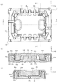
도 4는 본 실시형태에서의 제1 커넥터의 이면도이며, (a)는 평면도, (b)는 측면도이다.
도 5는 본 실시형태에서의 제1 커넥터의 분해도이다.
도 6은 본 실시형태에서의 제2 커넥터의 사시도이며, (a)는 감합면측에서 본 사시도, (b)는 실장면측에서 본 사시도이다.
도 7은 본 실시형태에서의 제2 커넥터의 이면도이며, (a)는 평면도, (b)는 측면도이다.
도 8은 본 실시형태에서의 제2 커넥터의 분해도이다.
도 9는 본 실시형태에서의 제1 커넥터와 제2 커넥터가 감합한 상태의 삼면도이며, (a)는 평면도, (b)는 (a)에서의 A-A 화살표 단면도, (c)는 (a)에서의 B-B 화살표 단면도이다.
도 10은 종래의 단자와 쉴드 부재를 나타내는 사시도이다.1 is a perspective view of a state in which a first connector and a second connector are fitted in this embodiment.
Fig. 2 is a perspective view of the first connector and the second connector before fitting in the present embodiment.
Fig. 3 is a perspective view of a first connector in the present embodiment, wherein (a) is a perspective view viewed from the mating surface side, and (b) is a perspective view viewed from the mounting surface side.
Fig. 4 is a rear view of the first connector in the present embodiment, (a) is a top view, and (b) is a side view.
5 is an exploded view of the first connector in this embodiment.
Fig. 6 is a perspective view of a second connector in the present embodiment, wherein (a) is a perspective view viewed from the mating surface side, and (b) is a perspective view viewed from the mounting surface side.
Fig. 7 is a rear view of the second connector in this embodiment, (a) is a top view, (b) is a side view.
8 is an exploded view of the second connector in this embodiment.
Fig. 9 is a three-dimensional view of a state in which a first connector and a second connector are fitted in the present embodiment, (a) is a plan view, (b) is a cross-sectional view taken by AA arrow in (a), and (c) is (a) BB arrow cross-section at .
10 is a perspective view showing a conventional terminal and shield member.
이하, 실시형태에 대하여 도면을 참조하면서 상세히 설명한다.EMBODIMENT OF THE INVENTION Hereinafter, embodiment is described in detail, referring drawings.
도 1은 본 실시형태에서의 제1 커넥터와 제2 커넥터가 감합한 상태의 사시도, 도 2는 본 실시형태에서의 제1 커넥터와 제2 커넥터의 감합 전의 사시도, 도 3은 본 실시형태에서의 제1 커넥터의 사시도, 도 4는 본 실시형태에서의 제1 커넥터의 이면도, 도 5는 본 실시형태에서의 제1 커넥터의 분해도이다. 또한, 도 3에서 (a)는 감합면측에서 본 사시도, (b)는 실장면측에서 본 사시도이며, 도 4에서 (a)는 평면도, (b)는 측면도이다.1 is a perspective view of a state in which a first connector and a second connector in this embodiment are mated, FIG. 2 is a perspective view of a first connector and a second connector in this embodiment before they are mated, and FIG. 3 is a perspective view in this embodiment. A perspective view of the first connector, Fig. 4 is a back view of the first connector in this embodiment, and Fig. 5 is an exploded view of the first connector in this embodiment. In Fig. 3, (a) is a perspective view viewed from the fitting surface side, (b) is a perspective view viewed from the mounting surface side, and in Fig. 4 (a) is a plan view and (b) is a side view.
도면에서, 101은 본 실시형태에서의 커넥터이며, 커넥터 조립체(커넥터 어셈블리)인 한 쌍의 커넥터 중 한쪽으로서의 제2 커넥터이다. 당해 제2 커넥터(101)는 실장 부재로서의 도시되지 않은 기판인 제2 기판의 표면에 실장되는 표면 실장형 커넥터이며, 상대 커넥터로서의 제1 커넥터(1)와 서로 감합된다. 또한, 당해 제1 커넥터(1)는 한 쌍의 커넥터 중 다른쪽이며, 실장 부재로서의 도시되지 않는 기판인 제1 기판의 표면에 실장되는 표면 실장형 커넥터이다.In the drawing, 101 denotes a connector in this embodiment, and is a second connector as one of a pair of connectors that is a connector assembly (connector assembly). The
또한, 본 실시형태에서의 제1 커넥터(1) 및 제2 커넥터(101)는 바람직하게는, 기판으로서의 제1 기판 및 제2 기판을 전기적으로 접속하기 위해 사용하는 것이지만, 다른 부재를 전기적으로 접속하기 위해서도 사용할 수 있다. 상기 제1 기판 및 제2 기판은, 예를 들어 전자 기기 등에 사용되는 프린트 회로 기판, 플렉서블 플랫 케이블(FFC), 플렉서블 회로 기판(FPC) 등이지만, 어떠한 종류의 기판이어도 무방하다.In addition, the first connector 1 and the
또한, 본 실시형태에서 제1 커넥터(1) 및 제2 커넥터(101)의 각 부의 구성 및 동작을 설명하기 위해 사용되는 상, 하, 좌, 우, 전, 후 등의 방향을 나타내는 표현은 절대적인 것이 아니라 상대적인 것이며, 상기 제1 커넥터(1) 및 제2 커넥터(101)의 각 부가 도면에 나타나는 자세인 경우에 적절하지만, 그 자세가 변화한 경우에는 자세의 변화에 따라 변경하여 해석되어야 하는 것이다.In addition, in the present embodiment, expressions indicating directions such as up, down, left, right, front, back, etc. used to describe the configuration and operation of each part of the first connector 1 and the
그리고, 상기 제1 커넥터(1)는 합성 수지 등의 절연성 재료에 의해 일체적으로 형성된 상대 커넥터 본체로서의 제1 하우징(11)을 갖는다. 당해 제1 하우징(11)은 도면에 나타나는 바와 같이, 개략 직육면체인 개략 직사각형의 두꺼운 판상의 형상을 구비하며, 제2 커넥터(101)가 감입되는 측, 즉 감합면(11a)측(Z축 양의 방향측)에는, 주위가 둘러싸인 개략 직사각형의 오목부로서, 제2 커넥터(101)의 제2 하우징(111)과 감합하는 오목부로서의 제1 오목부(12)가 형성되어 있다. 그리고, 당해 제1 오목부(12) 내에는 제2 커넥터(101)의 감합면(111a)측에 형성된 후술되는 오목홈부(113)와 감합하는 섬으로서의 제1 볼록부(13)가 제1 하우징(11)과 일체적으로 형성되어 있다.And, the first connector 1 has a
또한, 상기 제1 볼록부(13)의 양측(Y축 양의 방향측 및 음의 방향측)에는 당해 제1 볼록부(13)와 평행하게 연장하여, 상기 제1 오목부(12)의 양측을 획정하는 상대 측벽부로서의 제1 측벽부(14)가 제1 하우징(11)과 일체적으로 형성되어 있다. 그리고, 상기 제1 볼록부(13) 및 제1 측벽부(14)는 제1 오목부(12)의 바닥면을 획정하는 바닥판(18)으로부터 상방(Z축 양의 방향)을 향해 돌출되고, 제1 하우징(11)의 길이 방향으로 연장한다. 이에 따라, 상기 제1 볼록부(13)의 양측에는 제1 오목부(12)의 일부로서, 제1 하우징(11)의 길이 방향으로 연장하는 가늘고 긴 오목부인 오목홈부(12a)가 형성된다.Further, both sides of the first convex portion 13 (on the positive and negative Y-axis sides) extend in parallel with the
여기서, 상기 제1 볼록부(13)의 양측 측면으로부터 오목홈부(12a)의 바닥면에 걸쳐서는 제1 단자 수용 캐비티(15)가 형성되어 있다. 도면에 나타나는 예에서, 제1 단자 수용 캐비티(15)는 상기 바닥판(18)을 판 두께 방향(Z축 방향)으로 관통하도록 형성된다. 또한, 상기 제1 단자 수용 캐비티(15) 중, 제1 볼록부(13)의 양측 측면에 형성된 오목홈 형상의 부분을 제1 단자 수용 내측 캐비티(15a)라고 칭하고, 제1 측벽부(14)에서의 제1 볼록부(13)와 대향하는 측면에 형성된 오목홈 형상의 부분을 제1 단자 수용 외측 캐비티(15b)라고 칭한다.Here, the first
본 실시형태에서, 제1 단자 수용 캐비티(15)는 제1 하우징(11)의 길이 방향으로 나란히 2개의 열을 형성하도록, 각 제1 볼록부(13)의 양측에 소정 피치로 복수개(도시되는 예에서는 3개)씩 형성되어 있다. 또한, 상기 제1 단자 수용 캐비티(15)의 피치 및 수는 적절히 변경할 수 있다. 그리고, 제1 단자 수용 캐비티(15)의 각각에 수용되어 제1 하우징(11)에 장전되는 상대 단자로서의 제1 단자(61)도 각 제1 볼록부(13)의 양측에 동일한 피치로 동일한 수씩 배설되어 있다.In this embodiment, a plurality of first terminal accommodating
또한, 각 제1 측벽부(14)를 따라 복수씩 배설된 제1 단자(61)는 모두 동일한 것이지만, 본 실시형태에서는 도 2에 나타나는 바와 같이, 편의상, 배설된 위치에 따라 식별 가능한 부호를 부여하고, 이들 부호를 사용한 설명이 이루어질 수 있음에 유의해야 한다. 또한, 제2 커넥터(101)가 구비하는 제2 단자(161)도 모두 동일한 것이지만, 제1 단자(61)에 대응하여, 마찬가지로 편의상, 배설된 위치에 따라 식별 가능한 부호를 부여하고, 이들 부호를 사용한 설명이 이루질 수 있음에 유의해야 한다.In addition, all of the
도 2에 나타나는 예에서는, 제1 하우징(11)의 폭 방향 우측(Y축 음의 방향측)에 위치하는 제1 단자(61)는 제1 단자(61A)로 총칭되며, 또한 제1 단자(61A)의 그룹 내에서는, 제1 하우징(11)의 길이 방향 앞측(X축 음의 방향측)부터 순서대로 제1 단자(61A1), 제1 단자(61A2) 및 제1 단자(61A3)로 개별적으로 칭해진다. 또한, 제1 하우징(11)의 폭 방향 좌측(Y축 양의 방향측)에 위치하는 제1 단자(61)는 제1 단자(61B)로 총칭되며, 또한 제1 단자(61B)의 그룹 내에서는, 제1 하우징(11)의 길이 방향 안측(X축 양의 방향측)부터 순서대로 제1 단자(61B1), 제1 단자(61B2) 및 제1 단자(61B3)로 개별적으로 칭해진다. 그리고, 제2 단자(161)는 제1 단자(61A) 및 제1 단자(61B)에 대응하는 그룹이 각각 제2 단자(161A) 및 제2 단자(161B)로 총칭되며, 제2 단자(161A)의 그룹 내에서는, 제1 단자(61A1), 제1 단자(61A2) 및 제1 단자(61A3)에 대응하는 것이 각각 제2 단자(161A1), 제2 단자(161A2) 및 제2 단자(161A3)로 개별적으로 칭해지고, 제2 단자(161B)의 그룹 내에서는, 제1 단자(61B1), 제1 단자(61B2) 및 제1 단자(61B3)에 대응하는 것이 각각 제2 단자(161B1), 제2 단자(161B2) 및 제2 단자(161B3)로 개별적으로 칭해진다.In the example shown in FIG. 2 , the
상기 제1 단자(61)는 도전성의 금속판에 펀칭하고, 굽힘 등의 가공을 실시함으로써 일체적으로 형성된 부재이며, 피유지부(63)와, 당해 피유지부(63)의 하단에 접속된 테일부(62)와, 상기 피유지부(63)의 상단에 접속된 상측 접속부(67)와, 당해 상측 접속부(67)의 하단에 접속되고, 상기 피유지부(63)와 대향하는 외측 접촉부(66)와, 당해 외측 접촉부(66)의 하단에 접속된 하측 접속부(64)와, 당해 하측 접속부(64)에서의 외측 접촉부(66)와 반대측의 단에 접속된 내측 접속부(65)를 구비한다.The
그리고, 상기 피유지부(63)는 상하 방향(Z축 방향), 즉 제1 하우징(11)의 두께 방향으로 연장하며, 상기 제1 단자 수용 외측 캐비티(15b) 내에 압입되어 유지되는 부분이다. 또한, 제1 단자(61)는 반드시 압입에 의해 제1 하우징(11)에 장착되는 것은 아니며, 오버 몰드 내지 인서트 성형에 의해 제1 하우징(11)과 일체화되는 것일 수도 있으나, 여기에서는 설명의 편의상, 피유지부(63)가 제1 단자 수용 외측 캐비티(15b) 내에 압입되어 유지되는 것인 경우에 대해 설명한다.Also, the held
또한, 상기 테일부(62)는 피유지부(63)에 대해 구부려 접속되며, 좌우 방향(Y축 방향), 즉 제1 하우징(11)의 폭 방향의 외방을 향해 연장하여, 제1 기판의 도전 트레이스에 연결된 접속 패드에 솔더링 등에 의해 접속된다.In addition, the
또한, 상기 상측 접속부(67)는 상방(Z축 양의 방향)을 향해 돌출되도록 약 180도 만곡한 부분이다. 상기 상측 접속부(67)에서의 피유지부(63)와 반대측의 하단에는, 하방(Z축 음의 방향)을 향해 연장하는 외측 접촉부(66)가 접속되어 있다. 당해 외측 접촉부(66)의 일부는 제1 하우징(11)의 폭 방향으로 내방을 향해 돌출되는 것이 바람직하다.In addition, the
또한, 상기 하측 접속부(64)는 상기 외측 접촉부(66)의 하단에 접속된 대략 U자 형상의 측면 형상을 구비하는 부분이다. 또한, 상기 내측 접속부(65)의 상단에는, 상방을 향하는 동시에 외측 접촉부(66)를 향해 돌출되도록 약 180도 만곡한 내측 접촉부(65a)가 접속되어 있다.In addition, the
상기 제1 단자(61)는 제1 하우징(11)의 하면(Z축 음의 방향면)인 실장면(11b)으로부터 제1 단자 수용 캐비티(15) 내에 압입되고, 피유지부(63)가 제1 측벽부(14)의 내측의 측면에 형성된 제1 단자 수용 외측 캐비티(15b)의 측벽에 의해 양측으로부터 협지됨으로써 제1 하우징(11)에 고정된다. 이 상태, 즉 제1 단자(61)가 제1 하우징(11)에 장전된 상태에서, 상기 내측 접촉부(65a)와 외측 접촉부(66)는 오목홈부(12a)의 좌우 양측에 위치하여 서로 마주보고 있다. 또한, 제1 하우징(11)의 길이 방향(X축 방향)에서 보아, 피유지부(63)는 대부분이 제1 단자 수용 외측 캐비티(15b) 내에 수용되고, 내측 접촉부(65a)는 대부분이 제1 단자 수용 내측 캐비티(15a) 내에 수용되어 있다. 또한, 테일부(62)의 하면은 실장면(11b)(바닥판(18)의 하면)보다 하방에 위치한다.The
또한, 제1 단자(61)는 금속판에 가공을 실시함으로써 일체적으로 형성된 부재이기 때문에, 어느 정도의 탄성을 구비한다. 그리고, 그 형상으로부터 명백한 바와 같이, 서로 마주보는 내측 접촉부(65a)와 외측 접촉부(66)의 간격은 탄성적으로 변화 가능하다. 즉, 내측 접촉부(65a)와 외측 접촉부(66)의 사이에 제2 커넥터(101)가 구비하는 제2 단자(161)가 삽입되면, 그에 따라 내측 접촉부(65a)와 외측 접촉부(66)의 간격은 탄성적으로 신장한다.In addition, since the
또한, 상기 제1 하우징(11)의 길이 방향 양단에는 상대 감합 가이드부로서의 제1 돌출 단부(21)가 각각 배설되어 있다. 각 제1 돌출 단부(21)에는 상기 제1 오목부(12)의 일부로서 감합 오목부(22)가 형성되어 있다. 당해 감합 오목부(22)는 대략 직사각형의 오목부이며, 각 오목홈부(12a)의 길이 방향 양단에 접속되어 있다. 그리고, 상기 감합 오목부(22) 내에는, 제1 커넥터(1) 및 제2 커넥터(101)가 감합된 상태에서 당해 제2 커넥터(101)의 후술되는 제2 돌출 단부(122)가 삽입된다.In addition, first protruding ends 21 as mating guides are provided at both ends of the
또한, 상기 제1 볼록부(13)의 폭 방향(Y방향) 중앙에는, 길이 방향(X축 방향) 및 상하 방향(Z축 방향)으로 연장하는 슬릿 형상의 오목홈인 쉴드판 수용 슬릿(13a)이 형성되어 있다. 당해 쉴드판 수용 슬릿(13a)은 바닥판(18)의 하면으로 연속하여 개구되는 동시에, 제1 볼록부(13)의 상면으로 개구된다. 또한, 상기 쉴드판 수용 슬릿(13a)의 제1 볼록부(13)의 상면으로 개구되는 부분은 슬릿 분할부(13b)에 의해 길이 방향으로 둘로 나누어져 있다. 또한, 상기 쉴드판 수용 슬릿(13a)은 감합 오목부(22)의 바닥판(18)에 형성된 수평 암 수용 슬릿(22a)에 연접되어 있다. 당해 수평 암 수용 슬릿(22a)은 바닥판(18)을 두께 방향(Z축 방향)으로 관통하도록 형성되어 있다. 또한, 상기 수평 암 수용 슬릿(22a)은 제1 돌출 단부(21)의 제1 단벽부(21b)에 형성된 수직 암 수용 슬릿(23c)에 연접되어 있다.In addition, at the center of the width direction (Y direction) of the first
그리고, 상기 쉴드판 수용 슬릿(13a), 수평 암 수용 슬릿(22a) 및 수직 암 수용 슬릿(23c)에는, 도전성의 금속판에 펀칭 등의 가공을 실시함으로써 형성된 제1 하우징(11)의 두께 방향(Z축 방향) 및 길이 방향으로 연장하는 띠 형상의 판재인 쉴드판(56)이 수용되어 유지된다. 당해 쉴드판(56)은 개략 직사각형의 본체부(56a)와, 당해 본체부(56a)의 상단 에지로부터 하방으로 오목하게 들어가는 피유지 오목부(56b)와, 상기 본체부(56a)의 하단 에지로부터 하방으로 돌출되는 복수의 하볼록부(56c)와, 상기 본체부(56a)의 길이 방향 양단으로부터 제1 하우징(11)의 길이 방향으로 연장하는 한 쌍의 세장(細長) 수평 암(56d)과, 각 세장 수평 암(56d)의 말단부로부터 상방(Z축 양의 방향)으로 연장하는 수직 암(56e)과, 각 수직 암(56e)의 상단 근방으로부터 본체부(56a)를 향해 돌출되는 걸림결합 볼록부(56f)를 포함하고 있다. 상기 세장 수평 암(56d) 및 수직 암(56e)은 탄성적으로 변형 가능하여 스프링 부재로서 기능하기 때문에, 걸림결합 볼록부(56f)는 상기 본체부(56a)로부터 멀어지는 방향으로 탄성적으로 변위 가능하다. 그리고, 바닥판(18)의 하면측으로부터 쉴드판(56)이 쉴드판 수용 슬릿(13a) 내에 삽입 내지 압입되면, 슬릿 분할부(13b)가 상대적으로 피유지 오목부(56b) 내에 진입하여 걸림결합된다. 이에 따라, 쉴드판(56)은 쉴드판 수용 슬릿(13a)에 수용되어 유지된다. 또한, 세장 수평 암(56d) 및 수직 암(56e)은 각각 수평 암 수용 슬릿(22a) 및 수직 암 수용 슬릿(23c)에 수용된다.In the shield
또한, 쉴드판(56)은 반드시 삽입 내지 압입에 의해 제1 하우징(11)에 장착될 필요는 없으며, 오버 몰드 내지 인서트 성형에 의해 제1 하우징(11)과 일체화된 것일 수도 있으나, 여기에서는 설명의 편의상, 삽입 내지 압입에 의해 쉴드판 수용 슬릿(13a) 내에 수용되어 제1 하우징(11)에 장착된 것인 경우에 대해 설명한다.In addition, the
이와 같이 하여, 제1 하우징(11)에 쉴드판(56)이 장착되면, 좌우의 오목홈부(12a)를 따라 배열된 제1 단자(61)의 2개의 열 사이에 쉴드판(56)이 위치하기 때문에, 2개의 열의 제1 단자(61)끼리 사이의 크로스토크가 효과적으로 방지된다. 또한, 제1 하우징(11)에 쉴드판(56)이 장착된 상태에서, 감합면(11a)측에서는 본체부(56a)가 제1 볼록부(13)의 상면보다 하방에 위치하고, 세장 수평 암(56d) 및 수직 암(56e)이 각각 바닥판(18) 및 제1 단벽부(21b)로부터 감합 오목부(22) 내로 돌출되어 있지 않으나, 걸림결합 볼록부(56f)는 적어도 그 선단이 제1 단벽부(21b)로부터 감합 오목부(22) 내로 돌출되어 있다. 다만, 상기 세장 수평 암(56d) 및 수직 암(56e)은 바닥판(18) 및 제1 단벽부(21b)로부터 감합 오목부(22) 내로 돌출되어 있을 수도 있다. 또한, 실장면(11b)측에서, 하볼록부(56c) 및 세장 수평 암(56d)은 실장면(11b)(바닥판(18)의 하면)보다 하방으로는 돌출되어 있지 않는다.In this way, when the
또한, 상기 제1 돌출 단부(21)는 제1 측벽부(14)의 길이 방향 양단으로부터 제1 하우징(11)의 길이 방향으로 연장하는 상대 감합 가이드 측벽부로서의 제1 측벽 연장부(21c)와, 제1 하우징(11)의 폭 방향으로 연장하며, 양단이 제1 측벽 연장부(21c)에 접속된 제1 단벽부(21b)를 구비한다. 각 제1 돌출 단부(21)에서, 제1 단벽부(21b)와 그의 양단에 접속된 제1 측벽 연장부(21c)는 연속된 대략 コ 자 형상의 측벽을 형성하여, 대략 직사각형의 감합 오목부(22)의 삼방을 획정한다. 그리고, 상기 제1 단벽부(21b)에서, 외측면에는 오목하게 들어가는 외단 오목부(23a)가 형성되고, 내측면에는 오목하게 들어가는 내단 오목부(23b)가 형성되어 있다. 또한, 상기 제1 측벽 연장부(21c)에서, 외측면에는 오목하게 들어가는 외측 오목부(23e)가 형성되고, 내측면에는 오목하게 들어가는 내측 오목부(23d)가 형성되어 있다.In addition, the first
그리고, 상기 제1 하우징(11)에는, 이에 장전되는 상대 보강 금구로서의 제1 보강 금구(51)가 장착된다. 본 실시형태에서, 제1 보강 금구(51)는 금속판에 펀칭, 굽힘 등의 가공을 실시함으로써 일체적으로 형성된 부재이며, 제1 하우징(11)의 길이 방향(X축 방향) 양단에 위치하고, 제1 돌출 단부(21)의 제1 단벽부(21b)의 외측을 덮는 제1 단벽 복부(52)와, 제1 측벽 연장부(21c)의 외측을 덮는 제1 측벽 복부(53)를 포함하며, 평면에서 볼 때 대략 L자상의 형상을 갖는다.In addition, a first reinforcing
또한, 상기 제1 보강 금구(51)는 도 3 및 5에 나타나는 바와 같이, 제1 단벽 복부(52)가 제1 단벽부(21b)의 절반 이상의 범위를 덮는 대형 제1 보강 금구(51L)와, 제1 단벽 복부(52)가 제1 단벽부(21b)의 절반 미만의 범위를 덮는 소형 제1 보강 금구(51S)를 포함하고 있다. 또한, 제1 측벽 복부(53)에 대해서는, 대형 제1 보강 금구(51L) 및 소형 제1 보강 금구(51S)에서 그 치수 및 구성이 동일하며, 제1 단벽 복부(52)에 대해서도, 제1 하우징(11)의 폭 방향에 관한 치수를 제외하고, 대형 제1 보강 금구(51L) 및 소형 제1 보강 금구(51S)에서 그 치수 및 구성이 거의 동일하다. 이에, 상기 대형 제1 보강 금구(51L)와 소형 제1 보강 금구(51S)를 통합적으로 설명하는 경우에는, 제1 보강 금구(51)로서 설명한다.In addition, as shown in FIGS. 3 and 5, the first reinforcing
또한, 한 쌍의 대형 제1 보강 금구(51L)끼리 및 한 쌍의 소형 제1 보강 금구(51S)끼리는 평면에서 볼 때 대략 직사각형의 제1 하우징(11)의 대각선 상에서 서로 대향하는 위치에 배설되어 있다. 또한, 대형 제1 보강 금구(51L)끼리의 각각은 동일한 것이며, 소형 제1 보강 금구(51S)끼리의 각각은 동일한 것이지만, 본 실시형태에서는 도 2에 나타나는 바와 같이, 편의상, 배설된 위치에 따라 식별 가능한 부호를 부여하고, 이들 부호를 사용한 설명이 이루어질 수 있음에 유의해야 한다. 또한, 제2 커넥터(101)가 구비하는 제2 보강 금구(151)도 제1 보강 금구(51)에 대응하여, 마찬가지로 편의상, 배설된 위치에 따라 식별 가능한 부호를 부여하고, 이들 부호를 사용한 설명이 이루어질 수 있음에 유의해야 한다.In addition, a pair of large first reinforcing
도 2에 나타나는 예에서는, 제1 하우징(11)의 폭 방향 우측(Y축 음의 방향측)에 위치하는 제1 보강 금구(51)는 제1 하우징(11)의 길이 방향 앞측(X축 음의 방향측)의 구석에 위치하는 것이 대형 제1 보강 금구(51L)이며 제1 보강 금구(51LA)라고 칭해지고, 제1 하우징(11)의 길이 방향 안측(X축 양의 방향측)의 구석에 위치하는 것이 소형 제1 보강 금구(51S)이며 제1 보강 금구(51SA)라고 칭해진다. 또한, 제1 하우징(11)의 폭 방향 좌측(Y축 양의 방향측)에 위치하는 제1 보강 금구(51)는 제1 하우징(11)의 길이 방향 앞측의 구석에 위치하는 것이 소형 제1 보강 금구(51S)이며 제1 보강 금구(51SB)라고 칭해지고, 제1 하우징(11)의 길이 방향 안측의 구석에 위치하는 것이 대형 제1 보강 금구(51L)이며 제1 보강 금구(51LB)라고 칭해진다. 그리고, 제2 보강 금구(151)는 제1 보강 금구(51LA), 제1 보강 금구(51SA), 제1 보강 금구(51SB) 및 제1 보강 금구(51LB)에 대응하는 것이 각각 제2 보강 금구(151LA), 제2 보강 금구(151SA), 제2 보강 금구(151SB) 및 제2 보강 금구(151LB)라고 칭해진다.In the example shown in FIG. 2 , the first reinforcing
상기 제1 단벽 복부(52)는 제1 하우징(11)의 폭 방향으로 연장하여 제1 단벽부(21b)의 상면(21a)을 덮는 상면부(52a)와, 당해 상면부(52a)에서의 제1 단벽부(21b)의 내측단 에지로부터 비스듬히 하방을 향해 연장하는 유입부로서의 경사 내커버부(52b)와, 당해 경사 내커버부(52b)의 하단으로부터 하방을 향해 연장하는 수직 내커버부(52c)와, 당해 수직 내커버부(52c)의 측방 에지로부터 돌출되는 걸림결합 돌기(52d)와, 상기 상면부(52a)에서의 제1 단벽부(21b)의 외측단 에지로부터 하방을 향해 연장하는 외커버부(52e)와, 당해 외커버부(52e)의 측방 에지로부터 돌출되는 걸림결합 돌기(52f)와, 상기 외커버부(52e)의 하단에서의 접속 레그부(52g)를 포함하고 있다.The first
또한, 상기 제1 측벽 복부(53)는 제1 하우징(11)의 길이 방향으로 연장하여 제1 측벽 연장부(21c)의 상면(21a)을 덮는 상면부(53a)와, 당해 상면부(53a)에서의 제1 측벽 연장부(21c)의 내측단 에지로부터 비스듬히 하방을 향해 연장하는 상대 보강 금구 단자로서의 경사 탄성 암부(53b)와, 당해 경사 탄성 암부(53b)의 하단 근방에서 감합 오목부(22)의 중앙을 향해 팽출하는 접촉 볼록부(53c)와, 상기 상면부(53a)에서의 제1 측벽 연장부(21c)의 외측단 에지로부터 하방을 향해 연장하는 외커버부(53d)와, 당해 외커버부(53d)의 측방 에지로부터 돌출되는 걸림결합 돌기(53e)와, 상기 외커버부(53d)의 하단에서의 접속 레그부(53f)를 포함하고 있다.In addition, the first
상기 제1 보강 금구(51)는 경사 내커버부(52b), 수직 내커버부(52c), 외커버부(52e), 외커버부(53d) 등이 제1 하우징(11)의 상면(Z축 양의 방향면)인 감합면(11a)측으로부터 제1 단벽부(21b)의 내단 오목부(23b)나 외단 오목부(23a), 제1 측벽 연장부(21c)의 외측 오목부(23e) 등에 삽입 내지 압입되어, 제1 하우징(11)에 장착된다. 또한, 제1 보강 금구(51)는 반드시 삽입 내지 압입에 의해 제1 하우징(11)에 장착될 필요는 없으며, 오버 몰드 내지 인서트 성형에 의해 제1 하우징(11)과 일체화된 것일 수도 있으나, 여기에서는 설명의 편의상, 삽입 내지 압입에 의해 제1 하우징(11)에 장착된 것인 경우에 대해 설명한다.The first reinforcing
그리고, 제1 보강 금구(51)가 제1 하우징(11)에 장착된 상태에서, 제1 단벽 복부(52)의 상면부(52a)는 제1 단벽부(21b)의 상면(21a)의 과반을 덮고, 단벽 내커버부(52b) 및 수직 내커버부(52c)는 적어도 그 일부가 내단 오목부(23b) 내에 수용되고, 걸림결합 돌기(52d)는 내단 오목부(23b)의 측면의 일부로 파고 들어 걸림결합하며, 외커버부(52e)는 적어도 그 일부가 외단 오목부(23a) 내에 수용되고, 걸림결합 돌기(52f)는 외단 오목부(23a)의 측면의 일부로 파고 들어 걸림결합하며, 접속 레그부(52g)는 그 하면이 실장면(11b)(바닥판(18)의 하면)보다 하방에 위치하여, 제1 단자(61)의 테일부(62)의 하면과 거의 같은 평면상이 된다. 또한, 제1 측벽 복부(53)의 상면부(53a)는 제1 측벽 연장부(21c)의 상면(21a)의 과반을 덮고, 경사 탄성 암부(53b)는 적어도 그 일부가 내측 오목부(23d)의 바닥면으로부터 이간된 상태에서 당해 내측 오목부(23d) 내에 수용되고, 접촉 볼록부(53c)는 제1 측벽 연장부(21c)의 방향으로 탄성적으로 변위 가능하며, 외커버부(53d)는 적어도 그 일부가 외측 오목부(23e) 내에 수용되고, 걸림결합 돌기(53e)는 외측 오목부(23e)의 측면의 일부로 파고 들어 걸림결합되며, 접속 레그부(53f)는 그 하면이 실장면(11b)보다 하방에 위치하여, 제1 단자(61)의 테일부(62)의 하면과 거의 같은 평면상이 된다.And, in a state where the first reinforcing
이와 같이, 제1 단벽부(21b)와 제1 측벽 연장부(21c)의 표면의 과반이 제1 보강 금구(51)에 의해 덮이기 때문에, 제1 단벽부(21b)와 제1 측벽 연장부(21c)의 강도가 증가하여, 제1 커넥터(1)와 제2 커넥터(101)의 감합 작업 등에서 제1 단벽부(21b)와 제1 측벽 연장부(21c)에 힘이나 충격이 가해져도 제1 단벽부(21b)와 제1 측벽 연장부(21c)의 파손이나 변형을 확실하게 방지할 수 있다.In this way, since the majority of the surfaces of the first
또한, 대형 제1 보강 금구(51L)의 제1 단벽 복부(52)의 상면부(52a)는 반대측의 제1 측벽 연장부(21c)를 향해 연장하여, 그 말단부가 제1 하우징(11)의 폭 방향의 중심을 초과한 위치까지 도달한다. 따라서, 제1 하우징(11)의 폭 방향의 중심에 배설된 쉴드판(56)의 수직 암(56e)은 상기 대형 제1 보강 금구(51L)의 제1 단벽 복부(52)의 상면부(52a)의 하방에 위치하게 된다. 그러나, 쉴드판(56)의 수직 암(56e)은 어느 제1 보강 금구(51)의 어느 부분에도 접촉도 간섭도 하고 있지 않는다. 이와 같이, 제1 하우징(11)의 길이 방향의 양단에 장착된 제1 보강 금구(51)와, 제1 하우징(11)의 길이 방향으로 연장하여 그 양단의 제1 단벽부(21b)까지 도달하는 쉴드판(56)이 서로 독립되어 있기 때문에, 제1 하우징(11)은 전체적으로 어느 정도 유연하게 변형할 수 있어, 힘이나 충격이 가해져도 파손이나 변형을 방지할 수 있다.In addition, the
또한, 상기 경사 탄성 암부(53b)는 탄성적으로 변형 가능하며, 그 선단 근방에 형성된 접촉 볼록부(53c)가 제2 보강 금구(151)의 외커버부(153d)와 접촉하여 도통하는 단자로서도 기능한다. 즉, 경사 탄성 암부(53b)는 제1 단자(61)와 동일한 기능을 구비한다. 그 때문에, 경사 탄성 암부(53b)는 도 2에 나타나는 바와 같이, 제1 단자(61)와 마찬가지로, 배설된 위치에 따라 식별 가능한 부호를 부여하고, 이들 부호를 사용한 설명이 이루어질 수 있음에 유의해야 한다.In addition, the inclined
도 2에 나타나는 예에서는, 제1 하우징(11)의 폭 방향 우측에 위치하는 경사 탄성 암부(53b)는 제1 하우징(11)의 길이 방향 앞측부터 순서대로 제1 보강 금구 단자(53A1) 및 제1 보강 금구 단자(53A2)로 개별적으로 칭해지며, 제1 하우징(11)의 폭 방향 좌측에 위치하는 경사 탄성 암부(53b)는 제1 하우징(11)의 길이 방향 안측부터 순서대로 제1 보강 금구 단자(53B1) 및 제1 보강 금구 단자(53B2)로 개별적으로 칭해진다. 또한, 제2 보강 금구(151)의 외커버부(153d)는 제1 보강 금구 단자(53A1) 및 제1 보강 금구 단자(53A2), 및 제1 보강 금구 단자(53B1) 및 제1 보강 금구 단자(53B2)에 대응하는 것이 각각 제2 보강 금구 단자(153A1) 및 제2 보강 금구 단자(153A2), 및 제2 보강 금구 단자(153B1) 및 제2 보강 금구 단자(153B2)로 개별적으로 칭해진다.In the example shown in FIG. 2, the inclined
그리고, 제1 단벽 복부(52)의 접속 레그부(52g) 및 제1 측벽 복부(53)의 접속 레그부(53f)는 제1 단자(61)의 테일부(62)와 마찬가지로, 제1 기판의 도전 트레이스에 연결된 접속 패드에 솔더링 등에 의해 접속된다. 이에 따라, 제1 보강 금구(51)의 경사 탄성 암부(53b)도 제1 단자(61)와 마찬가지로, 전류 내지 전기 신호를 전송하기 위한 단자로서 기능시킬 수 있어, 제1 단자(61)의 수를 증가시키지 않고 제1 커넥터(1)의 극수를 증가시킬 수 있기 때문에, 제1 커넥터(1)를 소형화할 수 있다. 또한, 제1 하우징(11)의 길이 방향으로 연장하는 쉴드판(56)이 제1 단자(61)의 2개의 열 사이이며 제1 하우징(11)의 폭 방향의 중심에 배설되고 있기 때문에, 2개의 열의 제1 단자(61)끼리 사이의 크로스토크가 효과적으로 방지된다.And, the
다음으로, 제2 커넥터(101)의 구성에 대해 설명한다.Next, the configuration of the
도 6은 본 실시형태에서의 제2 커넥터의 사시도, 도 7은 본 실시형태에서의 제2 커넥터의 이면도, 도 8은 본 실시형태에서의 제2 커넥터의 분해도이다. 또한, 도 6에서 (a)는 감합면측에서 본 사시도, (b)는 실장면측에서 본 사시도이며, 도 7에서 (a)는 평면도, (b)는 측면도이다.Fig. 6 is a perspective view of the second connector in this embodiment, Fig. 7 is a back view of the second connector in this embodiment, and Fig. 8 is an exploded view of the second connector in this embodiment. In Fig. 6, (a) is a perspective view viewed from the fitting surface side, (b) is a perspective view viewed from the mounting surface side, and in Fig. 7 (a) is a plan view and (b) is a side view.
본 실시형태에서의 커넥터로서의 제2 커넥터(101)는 합성 수지 등의 절연성 재료에 의해 일체적으로 형성된 커넥터 본체로서의 제2 하우징(111)을 갖는다. 당해 제2 하우징(111)은 도면에 나타나는 바와 같이, 개략 직육면체인 개략 직사각형의 두꺼운 판상의 형상을 구비한다. 그리고, 제2 하우징(111)의 제1 커넥터(1)에 감입되는 측, 즉 감합면(111a)측(Z축 음의 방향측)에는, 제2 하우징(111)의 길이 방향(X축 방향)으로 연장하는 오목홈부(113)와, 당해 오목홈부(113)의 폭 방향(Y축 방향) 양측을 획정하는 동시에, 제2 하우징(111)의 길이 방향으로 연장하는 가늘고 긴 볼록부인 측벽부로서의 제2 측벽부(112)와, 상기 오목홈부(113)의 길이 방향(X축 방향) 양측을 획정하는 동시에, 제2 하우징(111)의 폭 방향(Y축 방향)으로 연장하여, 제2 측벽부(112)의 길이 방향 양단을 연결하는 감합 가이드부로서의 제2 돌출 단부(122)가 일체적으로 형성되어 있다.The
상기 제2 측벽부(112)는 오목홈부(113)의 양측을 따라, 또한 제2 하우징(111)의 양측을 따라 형성되어 있다. 또한, 각 제2 측벽부(112)에는, 단자로서의 제2 단자(161)가 배설되어 있다. 당해 제2 단자(161)는 제1 단자(61)에 대응하는 피치로, 또한 대응하는 수만큼 배설되어 있다. 상기 오목홈부(113)는 제2 기판에 실장되는 측, 즉 실장면측(Z축 양의 방향측)이 바닥판(118)에 의해 폐쇄되어 있다.The second
상기 제2 단자(161)는 도전성의 금속판에 펀칭, 굽힘 등의 가공을 실시함으로써 일체적으로 형성된 부재이며, 도 8에 나타나는 바와 같이, 외측 접촉부(165)와, 당해 외측 접촉부(165)의 상단(Z축 음의 방향단)에 접속된 상측 접속부(164)와, 당해 상측 접속부(164)에 상단이 접속되고, 상기 외측 접촉부(165)와 평행하게 연장하는 내측 접촉부(166)와, 당해 내측 접촉부(166)의 하단(Z축 양의 방향단)에 접속된 테일부(162)를 구비한다.The
또한, 각 제2 측벽부(112)를 따라 복수씩 배설된 제2 단자(161)는 모두 동일한 것이지만, 상기 제1 단자(61)와 마찬가지로, 본 실시형태에서는 도 2에 나타나는 바와 같이, 편의상, 배설된 위치에 따라 식별 가능한 부호를 부여하고, 이들 부호를 사용한 설명이 이루어질 수 있음에 유의해야 한다.In addition, although the plurality of
그리고, 상기 제2 단자(161)는 오버 몰드 내지 인서트 성형에 의해 제2 하우징(111)과 일체화된다. 즉, 제2 하우징(111)은 제2 단자(161)를 미리 내부에 세팅한 금형의 캐비티 내에 합성 수지 등의 절연성 재료를 충전함으로써 성형된다. 이에 따라, 제2 단자(161)는 적어도 일부가 제2 하우징(111) 내에 매몰되도록 하여 제2 하우징(111)에 일체적으로 장착된다. 또한, 제2 단자(161)는 반드시 오버 몰드 내지 인서트 성형에 의해 제2 하우징(111)과 일체화하는 것은 아니며, 압입 등에 의해 제2 하우징(111)에 장착될 수도 있으나, 여기에서는 설명의 편의상, 오버 몰드 내지 인서트 성형에 의해 제2 하우징(111)과 일체화된 것인 경우에 대해 설명한다.And, the
상기 외측 접촉부(165)는 적어도 일부가 제2 측벽부(112)에서의 제2 하우징(111)의 폭 방향 외측을 향한 면에 노출된다. 또한, 상측 접속부(164)는 제2 측벽부(112)에서의 상측(Z축 음의 방향)의 면에 노출되어, 당해 면과 거의 같은 평면상이 된다. 또한, 내측 접촉부(166)는 제2 하우징(111)의 폭 방향 내측을 향한 면에 노출되어, 당해 면과 거의 같은 평면상이 된다. 또한, 상기 테일부(162)는 제2 측벽부(112)에서의 제2 하우징(111)의 폭 방향 외측을 향한 면의 하단으로부터 제2 하우징(111)의 폭 방향의 외방을 향해 연장하여, 제2 기판의 도전 트레이스에 연결된 접속 패드에 솔더링 등에 의해 접속된다.At least a portion of the
또한, 상기 제2 돌출 단부(122)에서, 제2 하우징(111)의 길이 방향 외측을 향한 단측면(122b)에는, 오목하게 들어가는 외단 오목부(123a)가 형성되고, 제2 하우징(111)의 폭 방향 외측을 향한 측면(122c)에는, 오목하게 들어가는 외측 오목부(123e)가 형성되어 있다.In addition, in the second
그리고, 상기 제2 하우징(111)에는, 거기에 장전되는 보강 금구로서의 제2 보강 금구(151)가 장착된다. 본 실시형태에서, 제2 보강 금구(151)는 금속판에 펀칭, 굽힘 등의 가공을 실시함으로써 일체적으로 형성된 부재이며, 제2 하우징(111)의 길이 방향 양단에 위치하고, 제2 돌출 단부(122)의 상면(122a) 및 단측면(122b)의 과반을 덮는 제2 단벽 복부(152)와, 당해 제2 단벽 복부(152)의 측단에 접속되어, 측면(122c)의 과반을 덮는 제2 측벽 복부(153)를 포함하고 있다.Then, a second reinforcing
또한, 상기 제2 보강 금구(151)는 도 6 및 8에 나타나는 바와 같이, 제2 단벽 복부(152)가 제2 돌출 단부(122)의 절반 이상의 범위를 덮는 대형 제2 보강 금구(151L)와, 제2 단벽 복부(152)가 제2 돌출 단부(122)의 절반 미만의 범위를 덮는 소형 제2 보강 금구(151S)를 포함하고 있다. 또한, 제2 측벽 복부(153)에 대해서는, 대형 제2 보강 금구(151L) 및 소형 제2 보강 금구(151S)에서 그 치수 및 구성이 동일하며, 제2 단벽 복부(152)에 대해서도, 제2 하우징(111)의 폭 방향에 관한 치수를 제외하고 대형 제2 보강 금구(151L) 및 소형 제2 보강 금구(151S)에서 그의 치수 및 구성이 거의 동일하다. 이에, 상기 대형 제2 보강 금구(151L)와 소형 제2 보강 금구(151S)를 통합적으로 설명하는 경우에는, 제2 보강 금구(151)로서 설명한다.In addition, as shown in FIGS. 6 and 8, the second reinforcing
또한, 한 쌍의 대형 제2 보강 금구(151L)끼리, 및 한 쌍의 소형 제2 보강 금구(151S)끼리는 평면에서 볼 때 대략 직사각형의 제2 하우징(111)의 대각선 상에서 서로 대향하는 위치에 배설되어 있다. 또한, 대형 제2 보강 금구(151L)끼리의 각각은 동일한 것이며, 소형 제2 보강 금구(151S)끼리의 각각은 동일한 것이지만, 본 실시형태에서는 도 2에 나타나는 바와 같이, 편의상, 배설된 위치에 따라 식별 가능한 부호를 부여하고, 이들 부호를 사용한 설명이 이루어질 수 있음에 유의해야 한다. 도 2에 나타나는 바와 같이, 대형 제2 보강 금구(151L) 및 소형 제2 보강 금구(151S)는 제2 커넥터(101)의 감합면(111a)이 제1 커넥터(1)의 감합면과 대향한 상태에서, 제1 커넥터(1)의 대형 제1 보강 금구(51L) 및 소형 제1 보강 금구(51S)와 각각 대향하도록 배치되어 있다.In addition, a pair of large second reinforcing
상기 제2 단벽 복부(152)는 제2 하우징(111)의 폭 방향으로 연장하여 제2 돌출 단부(122)의 상면(122a)을 덮는 상면부(152a)와, 당해 상면부(152a)에서의 제2 돌출 단부(122)의 외측단 에지로부터 하방을 향해 연장하는 외커버부(152e)와, 당해 외커버부(152e)의 측방 에지로부터 돌출되는 걸림결합 돌기(152f)와, 상기 외커버부(152e)의 하단에서의 접속 레그부(152g)를 포함하고 있다.The second
또한, 상기 제2 측벽 복부(153)는 제2 하우징(111)의 길이 방향으로 연장하여 제2 돌출 단부(122)의 상면(122a)의 측방 에지 근방을 덮는 상면부(153a)와, 당해 상면부(153a)에서의 제2 측벽 복부(153)의 측단 에지로부터 하방을 향해 연장하는 외커버부(153d)와, 당해 외커버부(153d)의 측방 에지로부터 돌출되는 걸림결합 돌기(153e)와, 상기 외커버부(153d)의 하단에서의 접속 레그부(153f)를 포함하고 있다.In addition, the second
상기 제2 보강 금구(151)는 외커버부(152e), 외커버부(153d) 등이 제2 하우징(111)의 상면(Z축 음의 방향면)인 감합면(111a)측으로부터 제2 돌출 단부(122)의 외단 오목부(123a), 외측 오목부(123e) 등에 삽입 내지 압입되어, 제2 하우징(111)에 장착된다. 또한, 제2 보강 금구(151)는 반드시 삽입 내지 압입에 의해 제2 하우징(111)에 장착될 필요는 없으며, 오버 몰드 내지 인서트 성형에 의해 제2 하우징(111)과 일체화된 것일 수도 있으나, 여기에서는 설명의 편의상, 삽입 내지 압입에 의해 제2 하우징(111)에 장착된 것인 경우에 대해 설명한다.The second reinforcing
그리고, 제2 보강 금구(151)가 제2 하우징(111)에 장착된 상태에서, 제2 단벽 복부(152)의 상면부(152a)는 제2 돌출 단부(122)의 상면(122a)의 과반을 덮고, 외커버부(152e)는 적어도 그 일부가 외단 오목부(123a) 내에 수용되고, 걸림결합 돌기(152f)는 외단 오목부(123a)의 측면의 일부로 파고 들어 걸림결합하며, 접속 레그부(152g)는 그의 하면이 실장면(111b), 즉 바닥판(118)의 하면(Z축 양의 방향면)과 동일 면 상 또는 보다 하방에 위치하여, 제2 단자(161)의 테일부(162)의 하면과 거의 같은 평면상이 된다. 또한, 제2 측벽 복부(153)의 상면부(153a)는 제2 돌출 단부(122)의 상면(122a)의 측단 근방을 덮고, 외커버부(153d)는 적어도 그 일부가 외측 오목부(123e) 내에 수용되고, 걸림결합 돌기(153e)는 외측 오목부(123e)의 측면의 일부로 파고 들어 걸림결합하며, 접속 레그부(153f)는 그의 하면이 실장면(111b)과 동일 면 상 또는 보다 하방에 위치하여, 제2 단자(161)의 테일부(162)의 하면과 거의 같은 평면상이 된다.And, in a state where the second reinforcing
이와 같이, 제2 돌출 단부(122)의 표면의 과반이 제2 보강 금구(151)에 의해 덮이기 때문에, 제2 돌출 단부(122)의 강도가 증가하여, 제1 커넥터(1)와 제2 커넥터(101)의 감합 작업 등에서 제2 돌출 단부(122)에 힘이나 충격이 가해져도 제2 돌출 단부(122)의 파손이나 변형을 확실하게 방지할 수 있다.In this way, since the majority of the surface of the second
또한, 대형 제2 보강 금구(151L)의 제2 단벽 복부(152)의 상면부(152a) 및 외커버부(152e)는 반대측의 제2 측벽부(112)를 향해 연장하여, 그의 말단부가 제2 하우징(111)의 폭 방향의 중심을 초과한 위치이며 제1 커넥터(1)의 대형 제1 보강 금구(51L)에서의 제1 단벽 복부(52)의 상면부(52a)의 말단부와 동일한 위치까지 도달한다. 그 때문에, 도 1에 나타나는 바와 같이, 제2 커넥터(101)가 제1 커넥터(1)와 감합한 상태에서, 대형 제2 보강 금구(151L)의 외커버부(152e)는 제1 하우징(11)의 폭 방향의 중심에 배설된 쉴드판(56)의 수직 암(56e)과 대향하고, 당해 수직 암(56e)의 걸림결합 볼록부(56f)와 걸림결합하여 접촉한다.In addition, the
그리고, 제2 단벽 복부(152)의 접속 레그부(152g) 및 제2 측벽 복부(153)의 접속 레그부(153f)는 제2 단자(161)의 테일부(162)와 마찬가지로, 제2 기판의 도전 트레이스에 연결된 접속 패드에 솔더링 등에 의해 접속된다. 이에 따라, 제2 보강 금구(151)의 외커버부(153d)도 제2 단자(161)와 마찬가지로, 전류 내지 전기 신호를 전송하기 위한 단자로서 기능시킬 수 있어, 제2 단자(161)의 수를 증가시키지 않고 제2 커넥터(101)의 극수를 증가시킬 수 있기 때문에, 제2 커넥터(101)를 소형화할 수 있다. 또한, 상기 외커버부(153d)는 모두 동일한 것이지만, 본 실시형태에서는 도 2에 나타나는 바와 같이, 편의상, 배설된 위치에 따라 식별 가능한 부호를 부여하고, 이들 부호를 사용한 설명이 이루어질 수 있음에 유의해야 한다.Also, the
다음으로, 상기 구성의 제1 커넥터(1)와 제2 커넥터(101)를 감합시키는 동작에 대해 설명한다.Next, an operation for fitting the first connector 1 and the
도 9는 본 실시형태에서의 제1 커넥터와 제2 커넥터가 감합한 상태의 삼면도이다. 또한, 도면에서 (a)는 평면도, (b)는 (a)에서의 A-A 화살표 단면도, (c)는 (a)에서의 B-B화살표 단면도다.Fig. 9 is a three-dimensional view of a state in which the first connector and the second connector are engaged in the present embodiment. In the drawing, (a) is a plan view, (b) is a cross-sectional view taken along the A-A arrow in (a), and (c) is a cross-sectional view taken along the B-B arrow in (a).
여기서, 제1 커넥터(1)는 제1 단자(61)의 테일부(62)가 도시되지 않은 제1 기판의 도전 트레이스에 연결된 접속 패드에 솔더링 등에 의해 접속되고, 제1 보강 금구(51)의 제1 단벽 복부(52)의 접속 레그부(52g) 및 제1 측벽 복부(53)의 접속 레그부(53f)의 하단이 제1 기판의 도전 트레이스에 연결된 접속 패드에 솔더링 등에 의해 접속됨으로써, 제1 기판에 표면 실장되어 있는 것으로 한다. 마찬가지로, 제2 커넥터(101)는 제2 단자(161)의 테일부(162)가 도시되지 않은 제2 기판의 도전 트레이스에 연결된 접속 패드에 솔더링 등에 의해 접속되고, 제2 보강 금구(151)의 제2 단벽 복부(152)의 접속 레그부(152g) 및 제2 측벽 복부(153)의 접속 레그부(153f)의 하단이 제2 기판의 도전 트레이스에 연결된 접속 패드에 솔더링 등에 의해 접속됨으로써, 제2 기판에 표면 실장되어 있는 것으로 한다.Here, the first connector 1 is connected to a connection pad where the
우선, 오퍼레이터는 제1 커넥터(1)의 제1 하우징(11)의 감합면(11a)과 제2 커넥터(101)의 제2 하우징(111)의 감합면(111a)을 대향시킨 상태로 하고, 도 2에 나타나는 바와 같이, 제2 커넥터(101)의 제2 측벽부(112)의 위치가 제1 커넥터(1)의 대응하는 오목홈부(12a)의 위치와 합치하고, 제2 커넥터(101)의 제2 돌출 단부(122)의 위치가 제1 커넥터(1)의 대응하는 감합 오목부(22)의 위치와 합치하면, 제1 커넥터(1)와 제2 커넥터(101)의 위치 결정이 완료된다.First, the operator makes the
이 상태에서, 제1 커넥터(1) 및/또는 제2 커넥터(101)를 상대측에 접근하는 방향, 즉 감합 방향(Z축 방향)으로 이동시키면, 제2 커넥터(101)의 제2 측벽부(112) 및 제2 돌출 단부(122)가 제1 커넥터(1)의 오목홈부(12a) 및 감합 오목부(22) 내에 삽입된다. 이에 따라, 도 1 및 9에 나타나는 바와 같이, 제1 커넥터(1)와 제2 커넥터(101)의 감합이 완료되면, 제1 단자(61)와 제2 단자(161)가 도통하고, 제1 보강 금구(51)와 제2 보강 금구(151)가 도통한 상태가 된다.In this state, when the first connector 1 and/or the
구체적으로는, 각 제1 단자(61)의 내측 접촉부(65a)와 외측 접촉부(66) 사이에 대응하는 제2 단자(161)가 삽입되어, 제1 단자(61)의 내측 접촉부(65a)와 제2 단자(161)의 내측 접촉부(166)가 접촉하고, 제1 단자(61)의 외측 접촉부(66)와 제2 단자(161)의 외측 접촉부(165)가 접촉한다. 이에 따라, 서로 대응하는 제1 단자(61)와 제2 단자(161)는 2개소에서 접촉하는, 이른바 복수 접점의 상태가 되기 때문에, 충격이나 진동을 받을 때 한쪽 접점이 이간되더라도 도통 상태를 유지할 수 있다.Specifically, the corresponding
또한, 도 9(c)에 나타나는 바와 같이, 각 제1 보강 금구(51)의 경사 탄성 암부(53b)의 접촉 볼록부(53c)가 대응하는 제2 보강 금구(151)의 외커버부(153d)와 걸림결합하여 접촉한다. 이에 따라, 서로 대응하는 제1 보강 금구(51)와 제2 보강 금구(151)는 충격이나 진동을 받을 때에도 탄성적으로 변위 가능한 접촉 볼록부(53c)가 외커버부(153d)와의 접촉을 유지하기 때문에, 도통 상태를 유지할 수 있다.In addition, as shown in Fig. 9(c), the
또한, 도 9(b)에 나타나는 바와 같이, 쉴드판(56)은 적어도 일부가 오목홈부(113) 내에 수용되고, 그 수직 암(56e)의 걸림결합 볼록부(56f)가 대형 제2 보강 금구(151L)의 외커버부(152e)와 걸림결합하여 접촉한다. 이에 따라, 쉴드판(56)과 대형 제2 보강 금구(151L)가 도통하여 등전위가 되며, 또한 대형 제2 보강 금구(151L)의 외커버부(153d)와 경사 탄성 암부(53b)의 접촉 볼록부(53c)가 접촉하는 대형 제1 보강 금구(51L)도 쉴드판(56)과 등전위가 된다. 따라서, 쉴드성이 향상된다.In addition, as shown in FIG. 9(b), at least a part of the
본 실시형태에서의 제1 커넥터(1) 및 제2 커넥터(101)는 다양한 전류 내지 전기 신호를 전송하는 도전 트레이스를 접속하기 위한 커넥터 조립체로서 사용 가능한데, 예를 들어 각각이 2개의 그라운드 라인을 수반하는 2개의 고주파(예를 들어, 주파수 10[㎓] 이상) 신호 라인의 도전 트레이스와, 두 쌍의 직류 전원 라인용 도전 트레이스를 접속하기 위해 사용하는 예에 대하여 설명한다.The first connector 1 and the
이 경우, 제1 커넥터(1)에서는, 예를 들어 제1 단자(61A1)의 테일부(62)를 제1 기판에서의 제1 고주파 신호 라인의 도전 트레이스에 연결된 접속 패드에 접속하고, 제1 단자(61A2)의 테일부(62) 및 제1 보강 금구(51LA)의 제1 단벽 복부(52)의 접속 레그부(52g) 및 제1 측벽 복부(53)의 접속 레그부(53f)를 상기 제1 고주파 신호 라인이 수반하는 2개의 그라운드 라인의 도전 트레이스에 연결된 접속 패드에 접속한다. 즉, 제1 기판의 제1 고주파 신호 라인의 도전 트레이스를 고주파 단자로서 기능하는 제1 단자(61A1)에 접속하고, 제1 고주파 신호 라인이 수반하는 2개의 그라운드 라인의 도전 트레이스를 각각 그라운드 단자로서 기능하는 제1 보강 금구 단자(53A1) 및 제1 단자(61A2)에 접속한다. 마찬가지로 하여, 제1 기판의 제2 고주파 신호 라인의 도전 트레이스를 고주파 단자로서 기능하는 제1 단자(61B1)에 접속하고, 제1 고주파 신호 라인이 수반하는 2개의 그라운드 라인의 도전 트레이스를 각각 그라운드 단자로서 기능하는 제1 보강 금구 단자(53B1) 및 제1 단자(61B2)에 접속한다.In this case, in the first connector 1, for example, the
또한, 제2 커넥터(101)에서는, 제2 기판의 제1 고주파 신호 라인의 도전 트레이스를 고주파 단자로서 기능하는 제2 단자(161A1)에 접속하고, 제1 고주파 신호 라인이 수반하는 2개의 그라운드 라인의 도전 트레이스를 각각 그라운드 단자로서 기능하는 제2 보강 금구 단자(153A1) 및 제2 단자(161A2)에 접속한다. 마찬가지로 하여, 제2 기판의 제2 고주파 신호 라인의 도전 트레이스를 고주파 단자로서 기능하는 제2 단자(161B1)에 접속하고, 제2 고주파 신호 라인이 수반하는 2개의 그라운드 라인의 도전 트레이스를 각각 그라운드 단자로서 기능하는 제2 보강 금구 단자(153B1) 및 제2 단자(161B2)에 접속한다.Further, in the
이에 따라, 제1 및 제2 고주파 신호 라인에 접속된 고주파 단자인 제1 단자(61A1) 및 제1 단자(61B1)의 양측에 각각 그라운드에 접속된 그라운드 단자인 제1 보강 금구 단자(53A1) 및 제1 단자(61A2), 및 제1 보강 금구 단자(53B1) 및 제1 단자(61B2)가 위치하기 때문에, 마치 제1 단자(61A1)를 중심으로 하는 의사적인 도파로, 및 제1 단자(61B1)를 중심으로 하는 의사적인 도파로가 형성된 상태가 된다. 따라서, 제1 및 제2 고주파 신호는 외부로부터의 노이즈의 영향을 받지 않는 동시에, 외부에 노이즈의 영향을 미치지 않고 전송된다.Accordingly, the first terminal 61A1, which is a high-frequency terminal connected to the first and second high-frequency signal lines, and the first reinforcing metal terminal 53A1, which is a ground terminal connected to the ground on both sides of the first terminal 61B1, respectively, and Since the first terminal 61A2, and the first reinforcing bracket terminal 53B1 and the first terminal 61B2 are located, it is like a simulated waveguide centered on the first terminal 61A1, and the first terminal 61B1 A pseudo waveguide centered on is formed. Therefore, the first and second high frequency signals are transmitted without being influenced by external noise and at the same time being not affected by external noise.
또한, 쉴드판(56)의 수직 암(56e)의 걸림결합 볼록부(56f)가 제2 보강 금구(151LA) 및 제2 보강 금구(151LB)의 외커버부(152e)와 걸림결합하여 접촉하기 때문에, 쉴드판(56)은 그랜드 라인에 접속된 상기 제2 보강 금구 단자(153A1) 및 제2 보강 금구 단자(153B1)와 등전위가 되어, 쉴드성이 향상된다.In addition, the engaging
또한, 평면에서 볼 때, 제1 단자(61A1)와 제1 단자(61B1)는 쉴드판(56)의 중심선(도시하지 않음)을 지나는 제1 하우징(11)의 폭 방향의 중심선(도시하지 않음)에 관하여 선대칭으로 되어 있지 않고, 제1 단자(61A1)와 제1 단자(61B1)를 잇는 직선은 제1 하우징(11)의 폭 방향의 중심선에 대해 직교하지 않고 경사져 있다. 때문에, 제1 단자(61A1)와 제1 단자(61B1)가 제1 하우징(11)의 폭 방향의 중심선에 관하여 선대칭으로 되어 있는 경우보다, 제1 단자(61A1)와 제1 단자(61B1)의 거리가 길어져 있다. 마찬가지로, 제2 단자(161A1)와 제2 단자(161B1)는 쉴드판(56)의 중심선을 지나는 제2 하우징(111)의 폭 방향의 중심선(도시하지 않음)에 관하여 선대칭으로 되어 있지 않고, 제2 단자(161A1)와 제2 단자(161B1)를 잇는 직선은 제2 하우징(111)의 폭 방향의 중심선에 대해 직교하지 않고 경사져 있다. 그 때문에, 제2 단자(161A1)와 제2 단자(161B1)가 제2 하우징(111)의 폭 방향의 중심선에 관하여 선대칭으로 되어 있는 경우보다, 제2 단자(161A1)와 제2 단자(161B1)의 거리가 길어져 있다. 따라서, 제1 고주파 신호와 제2 고주파 신호가 서로 간섭하기 어려워져, 크로스토크가 한층 더 저감된다.In plan view, the first terminal 61A1 and the first terminal 61B1 are formed along a center line (not shown) in the width direction of the
또한, 제1 단자(61A3) 및 제1 보강 금구 단자(53A2), 및 제1 단자(61B3) 및 제1 보강 금구 단자(53B2)는 제1 기판에서의 두 쌍의 직류 전원 라인용 플러스 및 마이너스의 도전 트레이스에 접속되어, 전원 단자로서 기능한다. 마찬가지로 하여, 제2 단자(161A3) 및 제2 보강 금구 단자(153A2), 및 제2 단자(161B3) 및 제2 보강 금구 단자(153B2)는 제2 기판에서의 두 쌍의 직류 전원 라인용 플러스 및 마이너스의 도전 트레이스에 접속되어, 전원 단자로서 기능한다.In addition, the first terminal 61A3 and the first reinforcing bracket terminal 53A2, and the first terminal 61B3 and the first reinforcing bracket terminal 53B2 are plus and minus for two pairs of DC power lines in the first board. It is connected to the conductive trace of and functions as a power supply terminal. Similarly, the second terminal 161A3 and the second reinforcing bracket terminal 153A2, and the second terminal 161B3 and the second reinforcing bracket terminal 153B2 are positive and It is connected to the negative conductive trace and functions as a power supply terminal.
또한, 반드시 이 예로 한정될 필요는 없으며, 제1 단자(61), 제1 보강 금구(51), 제2 단자(161) 및 제2 보강 금구(151)의 각각에 접속되는 도전 트레이스의 종류는 적절히 변경할 수 있다. 예를 들어, 제1 단자(61A3) 및 제1 보강 금구 단자(53A2), 및 제1 단자(61B3) 및 제1 보강 금구 단자(53B2)에는 고주파가 아닌 신호 라인을 접속할 수도 있다. 또한, 제1 단자(61) 및 제2 단자(161)의 수도 변경하는 것이 가능하며, 예를 들어 제1 단자(61A3) 및 제1 단자(61B3), 및 제2 단자(161A3) 및 제2 단자(161B3)를 생략할 수도 있다.In addition, it is not necessarily limited to this example, and the type of conductive trace connected to each of the
이와 같이, 본 실시형태에서, 제2 커넥터(101)는 제2 하우징(111)과, 제2 하우징(111)에 장착되는 제2 단자(161) 및 제2 보강 금구 단자(153A1, 153A2, 153B1, 153B2)를 가지고, 제1 커넥터(1)와 감합한다. 그리고, 제2 하우징(111)은 오목홈부(113)와, 제2 하우징(111)의 길이 방향으로 연장하여, 오목홈부(113)의 양측을 획정하는 제2 측벽부(112)를 포함하며, 제2 단자(161) 및 제2 보강 금구 단자(153A1, 153A2, 153B1, 153B2)는 각 제2 측벽부(112)를 따라 복수씩 배설되고, 각 제2 측벽부(112)를 따라 배설된 복수의 제2 단자(161) 및 제2 보강 금구 단자(153A1, 153A2, 153B1, 153B2)는 하나의 고주파 단자로서 기능하는 제2 단자(161A1) 및 제2 단자(161B1)와, 제2 단자(161A1) 및 제2 단자(161B1)의 양측에 각각 배설된 그라운드 단자로서 기능하는 제2 단자(161A2) 및 제2 단자(161B2), 및 제2 보강 금구 단자(153A1) 및 제2 보강 금구 단자(153B1)를 포함하며, 평면에서 볼 때, 양측의 제2 측벽부(112)를 따라 배설된 제2 단자(161A1)와 제2 단자(161B1)를 잇는 직선은 제2 하우징(111)의 폭 방향의 중심선에 대해 경사지고, 제1 커넥터(1)와 감합하면, 제1 커넥터(1)의 쉴드판(56)은 적어도 일부가 오목홈부(113) 내에 수용되어, 중심선을 따라 연장한다.As such, in the present embodiment, the
이에 따라, 쉴드판(56)이 제2 하우징(111)의 폭 방향의 중심선을 따라 연장하는 동시에, 고주파 단자의 양측에 그라운드 단자가 각각 배설되게 되어, 쉴드 효과가 향상되는 동시에, 양측의 제2 측벽부(112)를 따라 배설된 고주파 단자끼리를 잇는 직선이 제2 하우징(111)의 폭 방향의 중심선에 대해 경사짐으로써 고주파 단자끼리 사이의 거리가 길어지기 때문에, 크로스토크를 확실하게 저감할 수 있어 신뢰성이 향상된다.As a result, the
또한, 제2 단자(161) 및 제2 보강 금구 단자(153A1, 153A2, 153B1, 153B2) 중, 고주파 단자 및 그라운드 단자 이외의 단자는 전원 단자이다. 또한, 제2 단자(161) 및 제2 보강 금구 단자(153A1, 153A2, 153B1, 153B2)는 각 제2 측벽부(112)를 따라 적어도 4개씩 배설된다. 또한, 제2 하우징(111)은 길이 방향의 양단에 형성되어, 제1 하우징(11)의 제1 돌출 단부(21)에 형성된 감합 오목부(22)에 삽입되는 제2 돌출 단부(122)를 포함하고, 제2 돌출 단부(122)의 각각에는, 제2 하우징(111)의 폭 방향으로 2분할된 제2 보강 금구(151)가 장착되고, 2분할된 제2 보강 금구(151)의 한쪽은 고주파 단자의 양측에 각각 배설된 그라운드 단자 중 하나인 제2 보강 금구 단자(153A1, 153B1)를 포함하고 있다. 또한, 고주파 단자의 양측에 각각 배설된 그라운드 단자 중 하나인 제2 보강 금구 단자(153A1, 153B1)를 포함하는 2분할된 제2 보강 금구(151)의 한쪽은 평면에서 볼 때, 대략 직사각형의 제2 하우징(111)의 대각선 상에서 서로 대향하도록 제2 돌출 단부(122)에 장착되어 있다. 또한, 제1 커넥터(1)와 감합하면, 쉴드판(56)은 그의 길이방향 양단이 2분할된 제2 보강 금구(151)의 한쪽과 접촉한다. 또한, 2분할된 제2 보강 금구(151)의 한쪽은 다른쪽보다 제2 하우징(111)의 폭 방향의 치수가 크다.Moreover, among the
또한, 본 명세서의 개시는 적합하고 예시적인 실시형태에 관한 특징을 서술한 것이다. 여기에 첨부된 특허청구범위 내 및 그 취지 내에서의 다양한 다른 실시형태, 수정 및 변형은 당업자라면 본 명세서의 개시를 총람함으로써 당연히 생각해 내는 것이다.Further, the disclosure herein sets forth features relating to suitable and exemplary embodiments. Various other embodiments, modifications and variations within the scope and spirit of the claims appended hereto will naturally come to those skilled in the art from reading the disclosure herein.
본 개시는 커넥터에 적용할 수 있다.The present disclosure can be applied to connectors.
1: 제1 커넥터
11: 제1 하우징
11a, 111a: 감합면
11b, 111b: 실장면
12: 제1 오목부
12a, 113: 오목홈부
13: 제1 볼록부
13a: 쉴드판 수용 슬릿
13b: 슬릿 분할부
14: 제1 측벽부
15: 제1 단자 수용 캐비티
15a: 제1 단자 수용 내측 캐비티
15b: 제1 단자 수용 외측 캐비티
18, 118: 바닥판
21: 제1 돌출 단부
21a, 122a: 상면
21b: 제1 단벽부
21c: 제1 측벽 연장부
22: 감합 오목부
22a: 수평 암 수용 슬릿
23a, 123a: 외단 오목부
23b: 내단 오목부
23c: 수직 암 수용 슬릿
23d: 내측 오목부
23e, 123e: 외측 오목부
51, 51LA, 51LB, 51SA, 51SB: 제1 보강 금구
51L: 대형 제1 보강 금구
51S: 소형 제1 보강 금구
52: 제1 단벽 복부
52a, 53a, 152a, 153a: 상면부
52b: 경사 내커버부
52c: 수직 내커버부
52d, 52f, 53e, 152f, 153e: 걸림결합 돌기
52e, 53d, 152e, 153d: 외커버부
52g, 53f, 152g, 153f: 접속 레그부
53: 제1 측벽 복부
53A1, 53A2, 53B1, 53B2: 제1 보강 금구 단자
53b: 경사 탄성 암부
53c: 접촉 볼록부
56, 856: 쉴드판
56a: 본체부
56b: 피유지 오목부
56c: 하볼록부
56d: 세장 수평 암
56e: 수직 암
56f: 걸림결합 볼록부
61, 61A, 61A1, 61A2, 61A3, 61B, 61B1, 61B2, 61B3: 제1 단자
62, 162: 테일부
63: 피유지부
64: 하측 접속부
65: 내측 접속부
65a, 166: 내측 접촉부
66, 165: 외측 접촉부
67, 164: 상측 접속부
101: 제2 커넥터
111: 제2 하우징
112: 제2 측벽부
122: 제2 돌출 단부
122b: 단측면
122c: 측면
151, 151LA, 151LB, 151SA, 151SB: 제2 보강 금구
151L: 대형 제2 보강 금구
151S: 소형 제2 보강 금구
152: 제2 단벽 복부
153: 제2 측벽 복부
153A1, 153A2, 153B1, 153B2: 제2 보강 금구 단자
161, 161A, 161A1, 161A2, 161A3, 161B, 161B1, 161B2, 161B3: 제2 단자
851: 보강 금구
852, 857: 측벽 복부
861: 신호 단자1: first connector
11: first housing
11a, 111a: mating surface
11b, 111b: mounting surface
12: first concave portion
12a, 113: concave groove
13: first convex portion
13a: shield plate accommodating slit
13b: slit division
14: first side wall portion
15: first terminal accommodating cavity
15a: first terminal accommodating inner cavity
15b: outer cavity for receiving the first terminal
18, 118: bottom plate
21: first protruding end
21a, 122a: upper surface
21b: first end wall portion
21c: first side wall extension
22: fitting recess
22a: horizontal arm receiving slit
23a, 123a: outer concave portion
23b: inner end recess
23c: vertical arm receiving slit
23d: inner recess
23e, 123e: outer concave portion
51, 51LA, 51LB, 51SA, 51SB: first reinforcing bracket
51L: large first reinforcing bracket
51S: small first reinforcing bracket
52: first end wall abdomen
52a, 53a, 152a, 153a: upper surface
52b: inclined inner cover part
52c: vertical inner cover
52d, 52f, 53e, 152f, 153e: engaging projection
52e, 53d, 152e, 153d: outer cover portion
52g, 53f, 152g, 153f: connection leg portion
53: first side wall abdomen
53A1, 53A2, 53B1, 53B2: first reinforcing bracket terminal
53b: inclined elastic arm part
53c: contact convex portion
56, 856: shield plate
56a: body part
56b: held recess
56c lower convex portion
56d: long horizontal arm
56e: vertical arm
56f: engaging convex portion
61, 61A, 61A1, 61A2, 61A3, 61B, 61B1, 61B2, 61B3: first terminal
62, 162: tail part
63: covered part
64: lower connection
65: inner connection
65a, 166: inner contact portion
66, 165: outer contact
67, 164: upper connection part
101: second connector
111: second housing
112: second side wall portion
122: second protruding end
122b: single side
122c: side
151, 151LA, 151LB, 151SA, 151SB: second reinforcement bracket
151L: large second reinforcing bracket
151S: small second reinforcing bracket
152 second end wall abdomen
153: second side wall abdomen
153A1, 153A2, 153B1, 153B2: Second reinforcing bracket terminal
161, 161A, 161A1, 161A2, 161A3, 161B, 161B1, 161B2, 161B3: second terminal
851: reinforcement bracket
852, 857: side wall abdomen
861: signal terminal
Claims (12)
하우징, 상기 하우징에 장착되는 단자, 및 상기 하우징에 형성되는 4개의 보강 금구를 포함하고,
상기 4개의 보강 금구 각각은 단벽 복부 및 측벽 복부를 포함하고,
상기 단벽 복부 및 측벽 복부는 서로 연결되어 있고,
상기 단벽 복부는 접속 레그부를 갖는 외커버부를 포함하고,
상기 측벽 복부는 접속 레그부를 갖는 외커버부를 포함하고,
리셉터클 커넥터가 상대 커넥터와 감합하면, 상기 리셉터클 커넥터의 각각의 보강 금구는, 상기 각각의 보강 금구를 마주보는 상기 상대 커넥터의 각각의 상대 보강 금구와 접촉하는 것을 특징으로 하는,
리셉터클 커넥터.It is a receptacle connector,
It includes a housing, a terminal mounted on the housing, and four reinforcing brackets formed on the housing,
Each of the four reinforcing brackets includes a single wall web and a side wall web,
The single wall abdomen and the side wall abdomen are connected to each other,
The single wall abdomen includes an outer cover portion having a connecting leg portion,
The side wall abdomen includes an outer cover portion having a connection leg portion,
When the receptacle connector is mated with the mating connector, each reinforcing fitting of the receptacle connector is in contact with each mating reinforcing fitting of the mating connector facing the respective reinforcing fitting.
Receptacle connector.
상기 단벽 복부의 상기 외커버부의 상기 접속 레그부는 상기 리셉터클 커넥터의 길이 방향(X축방향)의 외측에 위치하고,
상기 측벽 복부의 상기 외커버부의 상기 접속 레그부는 상기 리셉터클 커넥터의 폭 방향(Y축방향)의 외측에 위치하는,
리셉터클 커넥터.According to claim 1,
The connection leg portion of the outer cover portion of the end wall abdomen is located outside the receptacle connector in the longitudinal direction (X-axis direction),
The connection leg portion of the outer cover portion of the side wall abdomen is located outside the receptacle connector in the width direction (Y-axis direction),
Receptacle connector.
상기 단벽 복부의 접속 레그부 및 측벽 복부의 접속 레그부는 상기 단자의 테일부의 하면과 실질적으로 동일 평면에 있는,
리셉터클 커넥터.According to claim 1,
The connection leg portion of the end wall abdomen and the connection leg portion of the side wall abdomen are substantially coplanar with the lower surface of the tail portion of the terminal,
Receptacle connector.
상기 리셉터클 커넥터의 상기 측벽 복부는 경사 탄성 암부를 갖고,
상기 경사 탄성 암부는 상기 상대 커넥터의 상기 측벽 복부의 상기 외커버부와 접촉하는,
리셉터클 커넥터.According to claim 1,
The side wall abdomen of the receptacle connector has an inclined elastic arm portion;
The inclined elastic arm portion contacts the outer cover portion of the side wall abdomen of the mating connector.
Receptacle connector.
상기 단벽 복부는 상면부를 통해 상기 측벽 복부와 연결되고,
상기 각각의 외커버부는 상기 하우징의 외측단 에지로부터 상기 상면부 상에서 하방으로 연장되는,
리셉터클 커넥터.According to claim 1,
The single wall abdomen is connected to the side wall abdomen through an upper surface portion,
Each of the outer cover portions extends downward on the upper surface portion from the outer edge of the housing.
Receptacle connector.
하우징, 상기 하우징에 장착되는 단자, 및 상기 하우징에 형성되는 4개의 보강 금구를 포함하고,
상기 4개의 보강 금구 각각은 단벽 복부 및 측벽 복부를 포함하고,
상기 단벽 복부 및 측벽 복부는 서로 연결되어 있고,
상기 단벽 복부는 접속 레그부를 갖는 외커버부를 포함하고,
상기 측벽 복부는 접속 레그부를 갖는 외커버부를 포함하고,
플러그 커넥터가 상대 커넥터와 감합하면, 상기 플러그 커넥터의 각각의 보강 금구는, 상기 각각의 보강 금구를 마주보는 상기 상대 커넥터의 각각의 상대 보강 금구와 접촉하는 것을 특징으로 하는,
플러그 커넥터.It is a plug connector,
It includes a housing, a terminal mounted on the housing, and four reinforcing brackets formed on the housing,
Each of the four reinforcing brackets includes a single wall web and a side wall web,
The single wall abdomen and the side wall abdomen are connected to each other,
The single wall abdomen includes an outer cover portion having a connecting leg portion,
The side wall abdomen includes an outer cover portion having a connection leg portion,
When the plug connector is mated with the mating connector, each reinforcing bracket of the plug connector is in contact with each mating reinforcing bracket of the mating connector facing the respective reinforcing bracket.
plug connector.
커넥터 조립체.Including the receptacle connector of claim 1 and the plug connector of claim 6 fitting thereto,
connector assembly.
커넥터 및 상기 커넥터에 감합하도록 구성되는 감합 커넥터를 포함하고,
상기 커넥터 및 상기 감합 커넥터 각각은 총 4개의 보강 금구를 포함하고,
각각의 상기 커넥터 및 상기 감합 커넥터에 있어서,
상기 보강 금구는 단벽 복부 및 측벽 복부를 포함하고,
상기 단벽 복부 및 측벽 복부는 서로 연결되어 있고,
상기 단벽 복부는 외커버부를 포함하고, 상기 측벽 복부는 외커버부를 포함하고,
상기 양쪽의 외커버부 모두 각각 접속 레그부를 포함하고,
상기 커넥터의 각각의 보강 금구는, 상기 각각의 보강 금구를 마주보는 상기 감합 커넥터의 각각의 보강 금구와 접촉하는 것을 특징으로 하는,
커넥터 조립체.A connector assembly,
A connector and a mating connector configured to fit into the connector,
Each of the connector and the mating connector includes a total of four reinforcing brackets,
In each of the connector and the mating connector,
The reinforcing bracket includes a single wall web and a side wall web,
The single wall abdomen and the side wall abdomen are connected to each other,
The single wall web includes an outer cover portion, and the side wall web includes an outer cover portion,
Both outer cover parts each include a connection leg part,
Characterized in that each reinforcing bracket of the connector is in contact with each reinforcing bracket of the mating connector facing the respective reinforcing bracket.
connector assembly.
각각의 상기 커넥터 및 상기 감합 커넥터에 있어서, 상기 단벽 복부의 상기 외커버부의 상기 접속 레그부는 상기 커넥터 또는 상기 감합 커넥터의 길이 방향의 외측에 위치하고,
각각의 상기 커넥터 및 상기 감합 커넥터에 있어서, 상기 측벽 복부의 상기 외커버부의 상기 접속 레그부는 상기 커넥터 또는 상기 감합 커넥터의 폭 방향의 외측에 위치하는,
커넥터 조립체.According to claim 8,
In each of the connector and the mating connector, the connection leg portion of the outer cover portion on the abdomen of the end wall is located outside the connector or the mating connector in the longitudinal direction;
In each of the connector and the mating connector, the connection leg portion of the outer cover portion on the abdomen of the side wall is located outside the connector or the mating connector in a width direction.
connector assembly.
상기 커넥터는 단자를 포함하고,
상기 접속 레그부는 상기 단자의 테일부의 하면과 실질적으로 동일 평면에 있는,
커넥터 조립체.According to claim 8,
The connector includes a terminal,
The connection leg portion is substantially coplanar with the lower surface of the tail portion of the terminal,
connector assembly.
상기 커넥터의 상기 측벽 복부는 경사 탄성 암부를 갖고,
상기 경사 탄성 암부는 상기 감합 커넥터의 상기 측벽 복부의 상기 외커버부와 접촉하는,
커넥터 조립체.According to claim 8,
The side wall abdomen of the connector has an inclined elastic arm portion;
The inclined elastic arm portion contacts the outer cover portion of the side wall abdomen of the mating connector.
connector assembly.
각각의 상기 커넥터 및 상기 감합 커넥터에 있어서, 상기 단벽 복부는 상면부를 통해 상기 측벽 복부와 연결되고,
상기 커넥터는 외커버부를 포함하고, 상기 각각의 외커버부는 상기 상면부 상에서 하우징의 외측단 에지로부터 하방으로 연장되는,
커넥터 조립체.According to claim 8,
In each of the connector and the mating connector, the end wall web is connected to the side wall web through an upper surface portion;
The connector includes an outer cover portion, and each outer cover portion extends downward from an outer end edge of the housing on the upper surface portion.
connector assembly.
Priority Applications (2)
| Application Number | Priority Date | Filing Date | Title |
|---|---|---|---|
| KR1020230028322A KR102580251B1 (en) | 2019-12-10 | 2023-03-03 | Connector |
| KR1020230028325A KR102580253B1 (en) | 2019-12-10 | 2023-03-03 | Connector |
Applications Claiming Priority (3)
| Application Number | Priority Date | Filing Date | Title |
|---|---|---|---|
| JPJP-P-2019-222578 | 2019-12-10 | ||
| JP2019222578A JP7388901B2 (en) | 2019-12-10 | 2019-12-10 | connector |
| KR1020200168044A KR102482447B1 (en) | 2019-12-10 | 2020-12-04 | Connector |
Related Parent Applications (1)
| Application Number | Title | Priority Date | Filing Date |
|---|---|---|---|
| KR1020200168044A Division KR102482447B1 (en) | 2019-12-10 | 2020-12-04 | Connector |
Related Child Applications (2)
| Application Number | Title | Priority Date | Filing Date |
|---|---|---|---|
| KR1020230028322A Division KR102580251B1 (en) | 2019-12-10 | 2023-03-03 | Connector |
| KR1020230028325A Division KR102580253B1 (en) | 2019-12-10 | 2023-03-03 | Connector |
Publications (2)
| Publication Number | Publication Date |
|---|---|
| KR20230002249A true KR20230002249A (en) | 2023-01-05 |
| KR102517203B1 KR102517203B1 (en) | 2023-04-04 |
Family
ID=76209876
Family Applications (4)
| Application Number | Title | Priority Date | Filing Date |
|---|---|---|---|
| KR1020200168044A Active KR102482447B1 (en) | 2019-12-10 | 2020-12-04 | Connector |
| KR1020220182917A Active KR102517203B1 (en) | 2019-12-10 | 2022-12-23 | Connector |
| KR1020230028325A Active KR102580253B1 (en) | 2019-12-10 | 2023-03-03 | Connector |
| KR1020230028322A Active KR102580251B1 (en) | 2019-12-10 | 2023-03-03 | Connector |
Family Applications Before (1)
| Application Number | Title | Priority Date | Filing Date |
|---|---|---|---|
| KR1020200168044A Active KR102482447B1 (en) | 2019-12-10 | 2020-12-04 | Connector |
Family Applications After (2)
| Application Number | Title | Priority Date | Filing Date |
|---|---|---|---|
| KR1020230028325A Active KR102580253B1 (en) | 2019-12-10 | 2023-03-03 | Connector |
| KR1020230028322A Active KR102580251B1 (en) | 2019-12-10 | 2023-03-03 | Connector |
Country Status (5)
| Country | Link |
|---|---|
| US (2) | US11515670B2 (en) |
| JP (2) | JP7388901B2 (en) |
| KR (4) | KR102482447B1 (en) |
| CN (2) | CN113054490B (en) |
| TW (2) | TWI795194B (en) |
Families Citing this family (21)
| Publication number | Priority date | Publication date | Assignee | Title |
|---|---|---|---|---|
| TWI760873B (en) * | 2019-10-18 | 2022-04-11 | 日商村田製作所股份有限公司 | Connector |
| WO2021132721A1 (en) * | 2019-12-28 | 2021-07-01 | I-Pex株式会社 | Connector and connector unit |
| JP7417855B2 (en) | 2020-01-15 | 2024-01-19 | パナソニックIpマネジメント株式会社 | connector device |
| US11652323B2 (en) * | 2020-05-13 | 2023-05-16 | Japan Aviation Electronics Industry, Limited | Connector assembly comprising a connector encolsed by a shell and a mating connector enclosed by a mating shell |
| US11495919B2 (en) * | 2020-05-13 | 2022-11-08 | Japan Aviation Electronics Industry, Limited | Connector assembly in which ground terminals are coupled to form a shielding |
| CN114498200B (en) * | 2020-10-23 | 2024-01-16 | 富士康(昆山)电脑接插件有限公司 | Electric connector |
| US12230924B2 (en) * | 2021-02-18 | 2025-02-18 | Dongwoo Fine-Chem Co., Ltd. | Connector structure for antenna, antenna package and image display device |
| CN214505980U (en) | 2021-03-08 | 2021-10-26 | 富士康(昆山)电脑接插件有限公司 | Electric connector and butting connector thereof |
| JP2022172741A (en) * | 2021-05-07 | 2022-11-17 | モレックス エルエルシー | connector |
| JP7735112B2 (en) * | 2021-08-04 | 2025-09-08 | モレックス エルエルシー | connector |
| CN115706358A (en) * | 2021-08-16 | 2023-02-17 | 电连技术股份有限公司 | Socket connectors, plug connectors and connector assemblies |
| JP7783000B2 (en) * | 2021-09-29 | 2025-12-09 | 矢崎総業株式会社 | Board-mounted connector and board with connector |
| EP4386997A4 (en) | 2021-10-01 | 2024-11-20 | Samsung Electronics Co., Ltd. | CONNECTOR HAVING INCREASED RIGIDITY AND ELECTRONIC DEVICE COMPRISING SAME |
| JP7701255B2 (en) * | 2021-12-09 | 2025-07-01 | 日本航空電子工業株式会社 | Manufacturing method of electronic component and electronic component |
| JP7571739B2 (en) * | 2022-01-31 | 2024-10-23 | 株式会社村田製作所 | connector |
| KR102735061B1 (en) * | 2022-09-29 | 2024-11-28 | 에이치알에스코리아 주식회사 | Plug Connector |
| KR102698918B1 (en) * | 2022-11-09 | 2024-08-27 | 에이치알에스코리아 주식회사 | Plug connector |
| JP7735982B2 (en) * | 2022-11-10 | 2025-09-09 | 株式会社村田製作所 | Connector Set |
| JP7715126B2 (en) * | 2022-11-10 | 2025-07-30 | 株式会社村田製作所 | Connector Set |
| KR102700975B1 (en) * | 2023-06-13 | 2024-08-30 | 에이치알에스코리아 주식회사 | Plug Connector And Connector Assembly |
| WO2025187494A1 (en) * | 2024-03-07 | 2025-09-12 | 株式会社村田製作所 | Electrical connector and electrical connector set equipped with said electrical connector |
Citations (7)
| Publication number | Priority date | Publication date | Assignee | Title |
|---|---|---|---|---|
| JPH10106684A (en) * | 1996-09-25 | 1998-04-24 | Matsushita Electric Works Ltd | Connector |
| JP2016146292A (en) * | 2015-02-09 | 2016-08-12 | Smk株式会社 | Board connector device |
| JP2016207420A (en) * | 2015-04-21 | 2016-12-08 | 日本圧着端子製造株式会社 | Substrate-to-substrate connector |
| JP6319210B2 (en) * | 2015-07-02 | 2018-05-09 | Smk株式会社 | Connector and connector device |
| KR20180060651A (en) * | 2016-11-29 | 2018-06-07 | 히로세코리아 주식회사 | Mounting bracket and plug connector comprising the same |
| JP2018110087A (en) | 2017-01-06 | 2018-07-12 | ヒロセ電機株式会社 | Connector with shielding shield plate |
| KR20200110170A (en) * | 2019-03-15 | 2020-09-23 | 히로세덴끼 가부시끼가이샤 | Electric connector and electric connector assembly |
Family Cites Families (38)
| Publication number | Priority date | Publication date | Assignee | Title |
|---|---|---|---|---|
| JP3308132B2 (en) * | 1995-05-25 | 2002-07-29 | ケル株式会社 | Connector with ground plate |
| JPH1016684A (en) | 1996-06-27 | 1998-01-20 | Tadayoshi Tomishima | Holding tool of driving position |
| CN201160164Y (en) * | 2008-01-05 | 2008-12-03 | 富士康(昆山)电脑接插件有限公司 | electrical connector |
| JP4901944B2 (en) * | 2009-12-03 | 2012-03-21 | ヒロセ電機株式会社 | Electrical connector |
| JP5881333B2 (en) | 2010-09-08 | 2016-03-09 | モレックス エルエルシー | Board to board connector |
| JP6199666B2 (en) * | 2013-09-04 | 2017-09-20 | モレックス エルエルシー | Board to board connector |
| US20150079853A1 (en) * | 2013-09-13 | 2015-03-19 | Chou Hsien Tsai | Electrical connector |
| JP6245964B2 (en) * | 2013-12-02 | 2017-12-13 | モレックス エルエルシー | connector |
| US9391398B2 (en) * | 2014-03-20 | 2016-07-12 | Japan Aviation Electronics Industry, Limited | Connector assembly |
| JP2015220005A (en) * | 2014-05-15 | 2015-12-07 | Smk株式会社 | Board-to-board connector |
| JP6051242B2 (en) * | 2014-07-16 | 2016-12-27 | ヒロセ電機株式会社 | Circuit board electrical connector |
| JP6034339B2 (en) * | 2014-07-29 | 2016-11-30 | ヒロセ電機株式会社 | Circuit board electrical connector |
| JP6068405B2 (en) * | 2014-08-27 | 2017-01-25 | ヒロセ電機株式会社 | Electrical connector assembly |
| JP6391517B2 (en) * | 2015-03-30 | 2018-09-19 | モレックス エルエルシー | connector |
| JP6287977B2 (en) * | 2015-06-30 | 2018-03-07 | Smk株式会社 | connector |
| JP6513509B2 (en) * | 2015-07-01 | 2019-05-15 | 日本航空電子工業株式会社 | Board to Board Connectors and Connectors |
| JP6117415B1 (en) * | 2016-08-04 | 2017-04-19 | 京セラコネクタプロダクツ株式会社 | connector |
| JP2018067377A (en) * | 2016-10-17 | 2018-04-26 | 第一精工株式会社 | Electrical connector and connector device |
| JP6806028B2 (en) * | 2017-01-19 | 2020-12-23 | 株式会社村田製作所 | Multi-pole connector set |
| JP6842359B2 (en) | 2017-05-10 | 2021-03-17 | モレックス エルエルシー | connector |
| JP6761375B2 (en) * | 2017-05-29 | 2020-09-23 | 京セラ株式会社 | Electrical connector |
| CN109038013B (en) * | 2017-06-09 | 2020-01-10 | 莫列斯有限公司 | Connector and connector assembly |
| US10498058B1 (en) * | 2018-05-11 | 2019-12-03 | Molex, Llc | Connector and connector assembly |
| CN110504565A (en) * | 2018-05-18 | 2019-11-26 | 富士康(昆山)电脑接插件有限公司 | Electric connector and its docking connector |
| JP6493611B1 (en) | 2018-08-03 | 2019-04-03 | Smk株式会社 | Electrical connector |
| JP7253337B2 (en) * | 2018-08-22 | 2023-04-06 | モレックス エルエルシー | connector |
| JP7026025B2 (en) * | 2018-08-24 | 2022-02-25 | 日本航空電子工業株式会社 | Connector assembly and connector |
| JP7108531B2 (en) * | 2018-12-27 | 2022-07-28 | モレックス エルエルシー | connector assembly |
| CN209709216U (en) * | 2019-01-21 | 2019-11-29 | 王花瑞 | The plate of high-frequency signal is transmitted to board connecting equipment |
| CN209544752U (en) * | 2019-01-31 | 2019-10-25 | 王花瑞 | Transmit the anti-interference attachment device of high-frequency signal |
| TWM581777U (en) * | 2019-03-06 | 2019-08-01 | 于國基 | Board-to-board connector assembly and board-to-board connector thereof |
| CN209516221U (en) * | 2019-04-04 | 2019-10-18 | 昆山惠乐精密工业有限公司 | Electric connector combination and socket connector |
| CN209516069U (en) * | 2019-04-04 | 2019-10-18 | 昆山惠乐精密工业有限公司 | Board to board connector and socket connector |
| CN209571614U (en) * | 2019-04-18 | 2019-11-01 | 富士康(昆山)电脑接插件有限公司 | Electric connector and its docking connector |
| JP6813621B2 (en) * | 2019-05-16 | 2021-01-13 | モレックス エルエルシー | Connector to connector pair |
| JP7214609B2 (en) * | 2019-10-16 | 2023-01-30 | ヒロセ電機株式会社 | Connectors and connector devices |
| JP2021068608A (en) * | 2019-10-24 | 2021-04-30 | Smk株式会社 | connector |
| EP4386997A4 (en) * | 2021-10-01 | 2024-11-20 | Samsung Electronics Co., Ltd. | CONNECTOR HAVING INCREASED RIGIDITY AND ELECTRONIC DEVICE COMPRISING SAME |
-
2019
- 2019-12-10 JP JP2019222578A patent/JP7388901B2/en active Active
-
2020
- 2020-11-27 TW TW111103152A patent/TWI795194B/en active
- 2020-11-27 TW TW109141714A patent/TWI756941B/en active
- 2020-12-04 KR KR1020200168044A patent/KR102482447B1/en active Active
- 2020-12-08 US US17/114,500 patent/US11515670B2/en active Active
- 2020-12-09 CN CN202011447698.3A patent/CN113054490B/en active Active
- 2020-12-09 CN CN202310027027.9A patent/CN115799921A/en active Pending
-
2022
- 2022-10-20 US US17/969,726 patent/US12027802B2/en active Active
- 2022-12-23 KR KR1020220182917A patent/KR102517203B1/en active Active
-
2023
- 2023-03-03 KR KR1020230028325A patent/KR102580253B1/en active Active
- 2023-03-03 KR KR1020230028322A patent/KR102580251B1/en active Active
- 2023-08-31 JP JP2023141127A patent/JP7535165B2/en active Active
Patent Citations (8)
| Publication number | Priority date | Publication date | Assignee | Title |
|---|---|---|---|---|
| JPH10106684A (en) * | 1996-09-25 | 1998-04-24 | Matsushita Electric Works Ltd | Connector |
| JP2016146292A (en) * | 2015-02-09 | 2016-08-12 | Smk株式会社 | Board connector device |
| JP2016207420A (en) * | 2015-04-21 | 2016-12-08 | 日本圧着端子製造株式会社 | Substrate-to-substrate connector |
| JP6319210B2 (en) * | 2015-07-02 | 2018-05-09 | Smk株式会社 | Connector and connector device |
| KR20180060651A (en) * | 2016-11-29 | 2018-06-07 | 히로세코리아 주식회사 | Mounting bracket and plug connector comprising the same |
| JP2018110087A (en) | 2017-01-06 | 2018-07-12 | ヒロセ電機株式会社 | Connector with shielding shield plate |
| KR20180081441A (en) * | 2017-01-06 | 2018-07-16 | 히로세덴끼 가부시끼가이샤 | Connector with shield plate for shielding |
| KR20200110170A (en) * | 2019-03-15 | 2020-09-23 | 히로세덴끼 가부시끼가이샤 | Electric connector and electric connector assembly |
Also Published As
| Publication number | Publication date |
|---|---|
| KR20210073464A (en) | 2021-06-18 |
| TW202224286A (en) | 2022-06-16 |
| CN113054490B (en) | 2022-11-22 |
| US20230042553A1 (en) | 2023-02-09 |
| US20210175665A1 (en) | 2021-06-10 |
| JP7388901B2 (en) | 2023-11-29 |
| KR102482447B1 (en) | 2022-12-29 |
| JP2021093274A (en) | 2021-06-17 |
| KR20230035305A (en) | 2023-03-13 |
| CN115799921A (en) | 2023-03-14 |
| KR102580251B1 (en) | 2023-09-20 |
| CN113054490A (en) | 2021-06-29 |
| JP2023160893A (en) | 2023-11-02 |
| TW202127749A (en) | 2021-07-16 |
| KR102580253B1 (en) | 2023-09-20 |
| KR102517203B1 (en) | 2023-04-04 |
| TWI756941B (en) | 2022-03-01 |
| TWI795194B (en) | 2023-03-01 |
| US11515670B2 (en) | 2022-11-29 |
| US12027802B2 (en) | 2024-07-02 |
| JP7535165B2 (en) | 2024-08-15 |
| KR20230035023A (en) | 2023-03-10 |
Similar Documents
| Publication | Publication Date | Title |
|---|---|---|
| KR102517203B1 (en) | Connector | |
| KR102253273B1 (en) | Connector and connector assembly | |
| JP7108531B2 (en) | connector assembly | |
| JP7267186B2 (en) | Connectors and connector assemblies | |
| JP7102329B2 (en) | Connector and connector assembly | |
| JP2022172741A (en) | connector | |
| JP2023183819A (en) | Connectors and connector pairs | |
| JP7692711B2 (en) | connector |
Legal Events
| Date | Code | Title | Description |
|---|---|---|---|
| A107 | Divisional application of patent | ||
| PA0107 | Divisional application |
Comment text: Divisional Application of Patent Patent event date: 20221223 Patent event code: PA01071R01D Filing date: 20201204 Application number text: 1020200168044 |
|
| PA0201 | Request for examination | ||
| PG1501 | Laying open of application | ||
| E701 | Decision to grant or registration of patent right | ||
| PE0701 | Decision of registration |
Patent event code: PE07011S01D Comment text: Decision to Grant Registration Patent event date: 20230226 |
|
| GRNT | Written decision to grant | ||
| PR0701 | Registration of establishment |
Comment text: Registration of Establishment Patent event date: 20230329 Patent event code: PR07011E01D |
|
| PR1002 | Payment of registration fee |
Payment date: 20230330 End annual number: 3 Start annual number: 1 |
|
| PG1601 | Publication of registration |