KR20220144217A - 공작물 가공 장치 및 방법 - Google Patents
공작물 가공 장치 및 방법 Download PDFInfo
- Publication number
- KR20220144217A KR20220144217A KR1020210050612A KR20210050612A KR20220144217A KR 20220144217 A KR20220144217 A KR 20220144217A KR 1020210050612 A KR1020210050612 A KR 1020210050612A KR 20210050612 A KR20210050612 A KR 20210050612A KR 20220144217 A KR20220144217 A KR 20220144217A
- Authority
- KR
- South Korea
- Prior art keywords
- workpiece
- coordinates
- reference points
- predetermined measurement
- measurement reference
- Prior art date
- Legal status (The legal status is an assumption and is not a legal conclusion. Google has not performed a legal analysis and makes no representation as to the accuracy of the status listed.)
- Ceased
Links
Images




Classifications
-
- B—PERFORMING OPERATIONS; TRANSPORTING
- B23—MACHINE TOOLS; METAL-WORKING NOT OTHERWISE PROVIDED FOR
- B23Q—DETAILS, COMPONENTS, OR ACCESSORIES FOR MACHINE TOOLS, e.g. ARRANGEMENTS FOR COPYING OR CONTROLLING; MACHINE TOOLS IN GENERAL CHARACTERISED BY THE CONSTRUCTION OF PARTICULAR DETAILS OR COMPONENTS; COMBINATIONS OR ASSOCIATIONS OF METAL-WORKING MACHINES, NOT DIRECTED TO A PARTICULAR RESULT
- B23Q17/00—Arrangements for observing, indicating or measuring on machine tools
- B23Q17/24—Arrangements for observing, indicating or measuring on machine tools using optics or electromagnetic waves
- B23Q17/2409—Arrangements for indirect observation of the working space using image recording means, e.g. a camera
-
- B—PERFORMING OPERATIONS; TRANSPORTING
- B23—MACHINE TOOLS; METAL-WORKING NOT OTHERWISE PROVIDED FOR
- B23Q—DETAILS, COMPONENTS, OR ACCESSORIES FOR MACHINE TOOLS, e.g. ARRANGEMENTS FOR COPYING OR CONTROLLING; MACHINE TOOLS IN GENERAL CHARACTERISED BY THE CONSTRUCTION OF PARTICULAR DETAILS OR COMPONENTS; COMBINATIONS OR ASSOCIATIONS OF METAL-WORKING MACHINES, NOT DIRECTED TO A PARTICULAR RESULT
- B23Q17/00—Arrangements for observing, indicating or measuring on machine tools
- B23Q17/22—Arrangements for observing, indicating or measuring on machine tools for indicating or measuring existing or desired position of tool or work
- B23Q17/2233—Arrangements for observing, indicating or measuring on machine tools for indicating or measuring existing or desired position of tool or work for adjusting the tool relative to the workpiece
-
- B—PERFORMING OPERATIONS; TRANSPORTING
- B23—MACHINE TOOLS; METAL-WORKING NOT OTHERWISE PROVIDED FOR
- B23Q—DETAILS, COMPONENTS, OR ACCESSORIES FOR MACHINE TOOLS, e.g. ARRANGEMENTS FOR COPYING OR CONTROLLING; MACHINE TOOLS IN GENERAL CHARACTERISED BY THE CONSTRUCTION OF PARTICULAR DETAILS OR COMPONENTS; COMBINATIONS OR ASSOCIATIONS OF METAL-WORKING MACHINES, NOT DIRECTED TO A PARTICULAR RESULT
- B23Q17/00—Arrangements for observing, indicating or measuring on machine tools
- B23Q17/24—Arrangements for observing, indicating or measuring on machine tools using optics or electromagnetic waves
- B23Q17/2452—Arrangements for observing, indicating or measuring on machine tools using optics or electromagnetic waves for measuring features or for detecting a condition of machine parts, tools or workpieces
- B23Q17/2471—Arrangements for observing, indicating or measuring on machine tools using optics or electromagnetic waves for measuring features or for detecting a condition of machine parts, tools or workpieces of workpieces
-
- B—PERFORMING OPERATIONS; TRANSPORTING
- B23—MACHINE TOOLS; METAL-WORKING NOT OTHERWISE PROVIDED FOR
- B23Q—DETAILS, COMPONENTS, OR ACCESSORIES FOR MACHINE TOOLS, e.g. ARRANGEMENTS FOR COPYING OR CONTROLLING; MACHINE TOOLS IN GENERAL CHARACTERISED BY THE CONSTRUCTION OF PARTICULAR DETAILS OR COMPONENTS; COMBINATIONS OR ASSOCIATIONS OF METAL-WORKING MACHINES, NOT DIRECTED TO A PARTICULAR RESULT
- B23Q17/00—Arrangements for observing, indicating or measuring on machine tools
- B23Q17/24—Arrangements for observing, indicating or measuring on machine tools using optics or electromagnetic waves
- B23Q17/248—Arrangements for observing, indicating or measuring on machine tools using optics or electromagnetic waves using special electromagnetic means or methods
- B23Q17/249—Arrangements for observing, indicating or measuring on machine tools using optics or electromagnetic waves using special electromagnetic means or methods using image analysis, e.g. for radar, infrared or array camera images
-
- G—PHYSICS
- G01—MEASURING; TESTING
- G01B—MEASURING LENGTH, THICKNESS OR SIMILAR LINEAR DIMENSIONS; MEASURING ANGLES; MEASURING AREAS; MEASURING IRREGULARITIES OF SURFACES OR CONTOURS
- G01B5/00—Measuring arrangements characterised by the use of mechanical techniques
- G01B5/004—Measuring arrangements characterised by the use of mechanical techniques for measuring coordinates of points
- G01B5/008—Measuring arrangements characterised by the use of mechanical techniques for measuring coordinates of points using coordinate measuring machines
Landscapes
- Physics & Mathematics (AREA)
- Engineering & Computer Science (AREA)
- Mechanical Engineering (AREA)
- Optics & Photonics (AREA)
- General Physics & Mathematics (AREA)
- Computer Vision & Pattern Recognition (AREA)
- Radar, Positioning & Navigation (AREA)
- Remote Sensing (AREA)
- Electromagnetism (AREA)
- Length Measuring Devices With Unspecified Measuring Means (AREA)
Abstract
Description
도 2는 NC 가공에서의 좌표계를 도시한 도면이다.
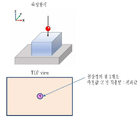
도 3은 본 발명의 일 실시예에 의해 공작물 좌표계를 설정하는 방법을 설명하기 위한 도면이다.
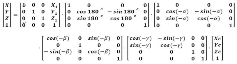
도 4는 본 발명의 일 실시예에 따라 3차원 좌표계 변환을 수행하여 공작물 원점을 획득하는 방법을 설명하기 위한 도면이다.
도 5a 내지 도 5d는 본 발명의 일 실시예에 따라 프로브 측정 매크로를 설정하는 방법을 설명하기 위한 도면이다.
도 6은 본 발명의 일 실시예에 의하여 어플리케이션을 통해 좌표계를 설정하는 방법을 설명하기 위한 도면이다.
도 7a 내지 도 7f는 본 발명의 일 실시예에 의해 측정유형별로 형상정의점을 지정하는 방법을 설명하기 위한 도면이다.
도 8a와 도 8b는 본 발명의 실시예에 따른 매크로 동작 방법을 설명하기 위한 도면이다.
도 9는 본 발명의 실시예에 따른, 컴퓨팅 장치를 나타내는 도면이다.




| 측정 유형 | 측정점 | 결과점 |
| Rectangle | 모서리 4개소 | 정중앙 (X, Y, Z) |
| Corner | 모서리 2개소 | 교차점 (X, Y, Z) |
| Parallel Edge | 모서리 2개소 | 중앙점 (X, Z OR Y, Z) |
| Edge | 모서리 1개소 | X, Z OR Y, Z |
| Circle | 모서리 4개소 | 정중앙 (X, Y, Z) |
| Z Depth | 1개소 | (X, Y, Z) |
| Distance | 2개소 | 두 점 사이의 3D 거리 |
3: 플레이트형 기판 4: 원기둥
5, 310: 깊이 카메라 6: 디스플레이부
7: 계측 시작점 8: 프로브
210: 기계 원점 220: 공작물 원점
300: CNC 제어기 302: 커넬부
304: PLC 부
Claims (10)
- 공작물 가공장치에 있어서,
변위 가능한 측정부;
디스플레이부;
상기 공작물 가공장치 내에 배치된 공작물의 3차원 이미지를 캡쳐하여 상기 디스플레이부에 표시하는 심도 카메라; 및
좌표계 설정을 위한 측정유형 및 상기 측정유형에 대응하는 소정 측정기준점들이 선택되면, 상기 소정 측정기준점들로 상기 측정부를 이동시키고, 상기 측정부에 의해 측정된 상기 소정 측정기준점들의 좌표에 기초하여 상기 공작물의 좌표계를 설정하는 제어부를 포함하되,
상기 소정 측정기준점들은,
상기 3차원 이미지로부터 획득되고, X축 좌표와 Y축 좌표 및 Z축 좌표로 구성되는, 공작물 가공장치. - 제1항에 있어서,
상기 제어부는,
상기 심도 카메라가 측정한 3차원 좌표인 제1좌표를 변환하여 상기 공작물의 원점인 제2좌표로 변환하고, 상기 제2좌표 및 상기 소정 측정기준점들의 좌표에 기초하여 상기 공작물의 좌표계를 설정하는, 공작물 가공장치. - 제1항에 있어서,
상기 측정부는,
상기 소정 측정기준점들과의 접촉을 감지하는 방식으로 상기 소정 측정기준점들의 좌표를 측정하는 측정 프로브를 포함하는 것을 특징으로 하는, 공작물 가공장치. - 제1항에 있어서,
상기 디스플레이부에는, 상기 측정유형에 대응하는 형상이 표시되고,
상기 제어부는, 상기 형상을 정의하기 위한 특징점들과 깊이 측정점으로 구성되는 상기 소정 측정기준점들을 표시하고, 상기 소정 측정기준점들에 대응하여 터치 입력이 수신되면 상기 소정 측정기준점들이 선택된 것으로 인식하는, 공작물 가공장치. - 제1항에 있어서,
상기 심도 카메라는,
적외선을 이용하여 이미지를 인식하는 적외선 카메라인 것을 특징으로 하는, 공작물 가공장치. - 공작물 가공방법에 있어서,
심도 카메라에 의해 공작물 가공장치 내에 배치된 공작물의 3차원 이미지를 캡쳐하여 디스플레이부에 표시하는 단계;
좌표계 설정을 위한 측정유형 및 상기 측정유형에 대응하는 소정 측정기준점들이 선택되는 단계;
상기 소정 측정기준점들로 상기 공작물 가공장치의 측정부를 이동시키는 단계; 및
상기 측정부에 의해 측정된 상기 소정 측정기준점들의 좌표에 기초하여 상기 공작물의 좌표계를 설정하는 단계를 포함하되,
상기 소정 측정기준점들은,
상기 3차원 이미지로부터 획득되고, X축 좌표와 Y축 좌표 및 Z축 좌표로 구성되는, 공작물 가공방법. - 제6항에 있어서,
상기 심도 카메라가 측정한 3차원 좌표인 제1좌표를 변환하여 상기 공작물의 원점인 제2좌표로 변환하고, 상기 제2좌표 및 상기 소정 측정기준점들의 좌표에 기초하여 상기 공작물의 좌표계를 설정하는, 공작물 가공방법. - 제6항에 있어서,
상기 측정부가 상기 소정 측정기준점들과의 접촉을 감지하는 방식으로 상기 소정 측정기준점들의 좌표를 측정하는 것을 특징으로 하는, 공작물 가공방법. - 제6항에 있어서,
상기 디스플레이부에는, 상기 측정유형에 대응하는 형상이 표시되고,
상기 형상을 정의하기 위한 특징점들과 깊이 측정점으로 구성되는 상기 소정 측정기준점들을 표시하고, 상기 소정 측정기준점들에 대응하여 터치 입력이 수신되면 상기 소정 측정기준점들이 선택된 것으로 인식하는, 공작물 가공방법. - 제6항에 있어서,
상기 심도 카메라는,
적외선을 이용하여 이미지를 인식하는 것을 특징으로 하는, 공작물 가공방법.
Priority Applications (1)
| Application Number | Priority Date | Filing Date | Title |
|---|---|---|---|
| KR1020210050612A KR20220144217A (ko) | 2021-04-19 | 2021-04-19 | 공작물 가공 장치 및 방법 |
Applications Claiming Priority (1)
| Application Number | Priority Date | Filing Date | Title |
|---|---|---|---|
| KR1020210050612A KR20220144217A (ko) | 2021-04-19 | 2021-04-19 | 공작물 가공 장치 및 방법 |
Publications (1)
| Publication Number | Publication Date |
|---|---|
| KR20220144217A true KR20220144217A (ko) | 2022-10-26 |
Family
ID=83785436
Family Applications (1)
| Application Number | Title | Priority Date | Filing Date |
|---|---|---|---|
| KR1020210050612A Ceased KR20220144217A (ko) | 2021-04-19 | 2021-04-19 | 공작물 가공 장치 및 방법 |
Country Status (1)
| Country | Link |
|---|---|
| KR (1) | KR20220144217A (ko) |
Cited By (3)
| Publication number | Priority date | Publication date | Assignee | Title |
|---|---|---|---|---|
| CN117973037A (zh) * | 2024-01-31 | 2024-05-03 | 长春理工大学 | 用于大型复杂光机系统装配的组合式测量基准设计方法 |
| CN119387636A (zh) * | 2024-09-14 | 2025-02-07 | 昌河飞机工业(集团)有限责任公司 | 一种工装测量方面关于法向孔修调的方法及装置 |
| KR20250025965A (ko) | 2023-08-16 | 2025-02-25 | 코웨이 주식회사 | 정수기 및 그 제어방법 |
Citations (1)
| Publication number | Priority date | Publication date | Assignee | Title |
|---|---|---|---|---|
| KR20190047106A (ko) | 2011-06-17 | 2019-05-07 | 삼성전자주식회사 | 밀리미터파 이동 광대역 통신 시스템에서 네트워크 진입을 위한 장치 및 방법 |
-
2021
- 2021-04-19 KR KR1020210050612A patent/KR20220144217A/ko not_active Ceased
Patent Citations (1)
| Publication number | Priority date | Publication date | Assignee | Title |
|---|---|---|---|---|
| KR20190047106A (ko) | 2011-06-17 | 2019-05-07 | 삼성전자주식회사 | 밀리미터파 이동 광대역 통신 시스템에서 네트워크 진입을 위한 장치 및 방법 |
Cited By (4)
| Publication number | Priority date | Publication date | Assignee | Title |
|---|---|---|---|---|
| KR20250025965A (ko) | 2023-08-16 | 2025-02-25 | 코웨이 주식회사 | 정수기 및 그 제어방법 |
| CN117973037A (zh) * | 2024-01-31 | 2024-05-03 | 长春理工大学 | 用于大型复杂光机系统装配的组合式测量基准设计方法 |
| CN117973037B (zh) * | 2024-01-31 | 2024-09-03 | 长春理工大学 | 用于大型复杂光机系统装配的组合式测量基准设计方法 |
| CN119387636A (zh) * | 2024-09-14 | 2025-02-07 | 昌河飞机工业(集团)有限责任公司 | 一种工装测量方面关于法向孔修调的方法及装置 |
Similar Documents
| Publication | Publication Date | Title |
|---|---|---|
| US8638984B2 (en) | Display of results of a measurement of workpieces as a function of the detection of the gesture of a user | |
| US10152044B2 (en) | Control device for machine tool | |
| US20200033109A1 (en) | Workpiece measurement device, workpiece measurement method and non-transitory computer readable medium recording a program | |
| US6968080B2 (en) | Method and apparatus for generating part programs for use in image-measuring instruments, and image-measuring instrument and method of displaying measured results therefrom | |
| KR20220144217A (ko) | 공작물 가공 장치 및 방법 | |
| US20030090483A1 (en) | Simulation apparatus for working machine | |
| US20170308055A1 (en) | Machine tool control method and machine tool control device | |
| US7724380B2 (en) | Method and system for three-dimensional measurement | |
| JP5113666B2 (ja) | ロボット教示システム及びロボットの動作のシミュレーション結果の表示方法 | |
| JP6570592B2 (ja) | 工作機械の機上測定方法および制御装置 | |
| US11045918B2 (en) | Method for determining an X-Y-Z reference coordinate of a workpiece, and machine tool | |
| JP2014512530A (ja) | 座標位置決め装置 | |
| JP2020086759A (ja) | 3次元モデル作成装置、加工シミュレーション装置、工具経路自動生成装置 | |
| JP5543476B2 (ja) | 工具衝突防止システム及び工具衝突防止方法 | |
| JP5649262B2 (ja) | 測定表示方法及び測定表示装置を備えた機械 | |
| JP2002267438A (ja) | 自由曲面形状測定方法 | |
| WO2021141051A1 (ja) | ワーク画像解析装置、ワーク画像解析方法、及びプログラム | |
| JP2019124609A (ja) | 3d形状のオートトレース方法及び測定機 | |
| WO2017007492A1 (en) | Machine display and machine control systems | |
| WO2020065854A1 (ja) | ワーク位置検出方法及び工作機械 | |
| JP3765061B2 (ja) | 多次元形状の座標計測機用オフライン・ティーチング・システム | |
| JP5230466B2 (ja) | 形状測定方法及び測定機能を有する機械 | |
| JP3853507B2 (ja) | 線幅測定方法及び装置 | |
| Ngom et al. | Basic design of a computer vision based controller for desktop NC engraving machine | |
| KR20210141866A (ko) | 회전오차 검출 키트 및 이를 구비하는 수치제어 공작기계 |
Legal Events
| Date | Code | Title | Description |
|---|---|---|---|
| PA0109 | Patent application |
St.27 status event code: A-0-1-A10-A12-nap-PA0109 |
|
| PA0201 | Request for examination |
St.27 status event code: A-1-2-D10-D11-exm-PA0201 |
|
| PG1501 | Laying open of application |
St.27 status event code: A-1-1-Q10-Q12-nap-PG1501 |
|
| E902 | Notification of reason for refusal | ||
| PE0902 | Notice of grounds for rejection |
St.27 status event code: A-1-2-D10-D21-exm-PE0902 |
|
| T11-X000 | Administrative time limit extension requested |
St.27 status event code: U-3-3-T10-T11-oth-X000 |
|
| T11-X000 | Administrative time limit extension requested |
St.27 status event code: U-3-3-T10-T11-oth-X000 |
|
| T11-X000 | Administrative time limit extension requested |
St.27 status event code: U-3-3-T10-T11-oth-X000 |
|
| AMND | Amendment | ||
| P11-X000 | Amendment of application requested |
St.27 status event code: A-2-2-P10-P11-nap-X000 |
|
| P13-X000 | Application amended |
St.27 status event code: A-2-2-P10-P13-nap-X000 |
|
| E601 | Decision to refuse application | ||
| PE0601 | Decision on rejection of patent |
St.27 status event code: N-2-6-B10-B15-exm-PE0601 |
|
| AMND | Amendment | ||
| P11-X000 | Amendment of application requested |
St.27 status event code: A-2-2-P10-P11-nap-X000 |
|
| P13-X000 | Application amended |
St.27 status event code: A-2-2-P10-P13-nap-X000 |
|
| PX0901 | Re-examination |
St.27 status event code: A-2-3-E10-E12-rex-PX0901 |
|
| PX0601 | Decision of rejection after re-examination |
St.27 status event code: N-2-6-B10-B17-rex-PX0601 |
|
| X601 | Decision of rejection after re-examination | ||
| J201 | Request for trial against refusal decision | ||
| PJ0201 | Trial against decision of rejection |
St.27 status event code: A-3-3-V10-V11-apl-PJ0201 |
|
| J301 | Trial decision |
Free format text: TRIAL NUMBER: 2024101001534; TRIAL DECISION FOR APPEAL AGAINST DECISION TO DECLINE REFUSAL REQUESTED 20240708 Effective date: 20240930 |
|
| PJ1301 | Trial decision |
St.27 status event code: A-3-3-V10-V15-crt-PJ1301 Decision date: 20240930 Appeal event data comment text: Appeal Kind Category : Appeal against decision to decline refusal, Appeal Ground Text : 2021 0050612 Appeal request date: 20240708 Appellate body name: Patent Examination Board Decision authority category: Office appeal board Decision identifier: 2024101001534 |