KR20220124125A - organic light emitting diode display - Google Patents
organic light emitting diode display Download PDFInfo
- Publication number
- KR20220124125A KR20220124125A KR1020220106909A KR20220106909A KR20220124125A KR 20220124125 A KR20220124125 A KR 20220124125A KR 1020220106909 A KR1020220106909 A KR 1020220106909A KR 20220106909 A KR20220106909 A KR 20220106909A KR 20220124125 A KR20220124125 A KR 20220124125A
- Authority
- KR
- South Korea
- Prior art keywords
- layer
- electrode
- angstroms
- light emitting
- thickness
- Prior art date
- Legal status (The legal status is an assumption and is not a legal conclusion. Google has not performed a legal analysis and makes no representation as to the accuracy of the status listed.)
- Granted
Links
Images


Classifications
-
- H—ELECTRICITY
- H10—SEMICONDUCTOR DEVICES; ELECTRIC SOLID-STATE DEVICES NOT OTHERWISE PROVIDED FOR
- H10D—INORGANIC ELECTRIC SEMICONDUCTOR DEVICES
- H10D86/00—Integrated devices formed in or on insulating or conducting substrates, e.g. formed in silicon-on-insulator [SOI] substrates or on stainless steel or glass substrates
- H10D86/40—Integrated devices formed in or on insulating or conducting substrates, e.g. formed in silicon-on-insulator [SOI] substrates or on stainless steel or glass substrates characterised by multiple TFTs
-
- H—ELECTRICITY
- H10—SEMICONDUCTOR DEVICES; ELECTRIC SOLID-STATE DEVICES NOT OTHERWISE PROVIDED FOR
- H10K—ORGANIC ELECTRIC SOLID-STATE DEVICES
- H10K59/00—Integrated devices, or assemblies of multiple devices, comprising at least one organic light-emitting element covered by group H10K50/00
- H10K59/80—Constructional details
- H10K59/805—Electrodes
- H10K59/8052—Cathodes
- H10K59/80523—Multilayers, e.g. opaque multilayers
-
- H01L51/5231—
-
- H01L27/3248—
-
- H01L51/5056—
-
- H01L51/5072—
-
- H01L51/5088—
-
- H01L51/5218—
-
- H01L51/5253—
-
- H01L51/5265—
-
- H—ELECTRICITY
- H10—SEMICONDUCTOR DEVICES; ELECTRIC SOLID-STATE DEVICES NOT OTHERWISE PROVIDED FOR
- H10D—INORGANIC ELECTRIC SEMICONDUCTOR DEVICES
- H10D86/00—Integrated devices formed in or on insulating or conducting substrates, e.g. formed in silicon-on-insulator [SOI] substrates or on stainless steel or glass substrates
- H10D86/40—Integrated devices formed in or on insulating or conducting substrates, e.g. formed in silicon-on-insulator [SOI] substrates or on stainless steel or glass substrates characterised by multiple TFTs
- H10D86/441—Interconnections, e.g. scanning lines
-
- H—ELECTRICITY
- H10—SEMICONDUCTOR DEVICES; ELECTRIC SOLID-STATE DEVICES NOT OTHERWISE PROVIDED FOR
- H10D—INORGANIC ELECTRIC SEMICONDUCTOR DEVICES
- H10D86/00—Integrated devices formed in or on insulating or conducting substrates, e.g. formed in silicon-on-insulator [SOI] substrates or on stainless steel or glass substrates
- H10D86/40—Integrated devices formed in or on insulating or conducting substrates, e.g. formed in silicon-on-insulator [SOI] substrates or on stainless steel or glass substrates characterised by multiple TFTs
- H10D86/60—Integrated devices formed in or on insulating or conducting substrates, e.g. formed in silicon-on-insulator [SOI] substrates or on stainless steel or glass substrates characterised by multiple TFTs wherein the TFTs are in active matrices
-
- H—ELECTRICITY
- H10—SEMICONDUCTOR DEVICES; ELECTRIC SOLID-STATE DEVICES NOT OTHERWISE PROVIDED FOR
- H10K—ORGANIC ELECTRIC SOLID-STATE DEVICES
- H10K50/00—Organic light-emitting devices
- H10K50/10—OLEDs or polymer light-emitting diodes [PLED]
- H10K50/14—Carrier transporting layers
- H10K50/15—Hole transporting layers
-
- H—ELECTRICITY
- H10—SEMICONDUCTOR DEVICES; ELECTRIC SOLID-STATE DEVICES NOT OTHERWISE PROVIDED FOR
- H10K—ORGANIC ELECTRIC SOLID-STATE DEVICES
- H10K50/00—Organic light-emitting devices
- H10K50/10—OLEDs or polymer light-emitting diodes [PLED]
- H10K50/14—Carrier transporting layers
- H10K50/16—Electron transporting layers
-
- H—ELECTRICITY
- H10—SEMICONDUCTOR DEVICES; ELECTRIC SOLID-STATE DEVICES NOT OTHERWISE PROVIDED FOR
- H10K—ORGANIC ELECTRIC SOLID-STATE DEVICES
- H10K50/00—Organic light-emitting devices
- H10K50/10—OLEDs or polymer light-emitting diodes [PLED]
- H10K50/17—Carrier injection layers
-
- H—ELECTRICITY
- H10—SEMICONDUCTOR DEVICES; ELECTRIC SOLID-STATE DEVICES NOT OTHERWISE PROVIDED FOR
- H10K—ORGANIC ELECTRIC SOLID-STATE DEVICES
- H10K50/00—Organic light-emitting devices
- H10K50/80—Constructional details
- H10K50/805—Electrodes
- H10K50/82—Cathodes
- H10K50/828—Transparent cathodes, e.g. comprising thin metal layers
-
- H—ELECTRICITY
- H10—SEMICONDUCTOR DEVICES; ELECTRIC SOLID-STATE DEVICES NOT OTHERWISE PROVIDED FOR
- H10K—ORGANIC ELECTRIC SOLID-STATE DEVICES
- H10K50/00—Organic light-emitting devices
- H10K50/80—Constructional details
- H10K50/84—Passivation; Containers; Encapsulations
- H10K50/844—Encapsulations
-
- H—ELECTRICITY
- H10—SEMICONDUCTOR DEVICES; ELECTRIC SOLID-STATE DEVICES NOT OTHERWISE PROVIDED FOR
- H10K—ORGANIC ELECTRIC SOLID-STATE DEVICES
- H10K50/00—Organic light-emitting devices
- H10K50/80—Constructional details
- H10K50/86—Arrangements for improving contrast, e.g. preventing reflection of ambient light
-
- H—ELECTRICITY
- H10—SEMICONDUCTOR DEVICES; ELECTRIC SOLID-STATE DEVICES NOT OTHERWISE PROVIDED FOR
- H10K—ORGANIC ELECTRIC SOLID-STATE DEVICES
- H10K59/00—Integrated devices, or assemblies of multiple devices, comprising at least one organic light-emitting element covered by group H10K50/00
- H10K59/10—OLED displays
- H10K59/12—Active-matrix OLED [AMOLED] displays
- H10K59/123—Connection of the pixel electrodes to the thin film transistors [TFT]
-
- H—ELECTRICITY
- H10—SEMICONDUCTOR DEVICES; ELECTRIC SOLID-STATE DEVICES NOT OTHERWISE PROVIDED FOR
- H10K—ORGANIC ELECTRIC SOLID-STATE DEVICES
- H10K59/00—Integrated devices, or assemblies of multiple devices, comprising at least one organic light-emitting element covered by group H10K50/00
- H10K59/80—Constructional details
- H10K59/805—Electrodes
- H10K59/8051—Anodes
- H10K59/80518—Reflective anodes, e.g. ITO combined with thick metallic layers
-
- H—ELECTRICITY
- H10—SEMICONDUCTOR DEVICES; ELECTRIC SOLID-STATE DEVICES NOT OTHERWISE PROVIDED FOR
- H10K—ORGANIC ELECTRIC SOLID-STATE DEVICES
- H10K59/00—Integrated devices, or assemblies of multiple devices, comprising at least one organic light-emitting element covered by group H10K50/00
- H10K59/80—Constructional details
- H10K59/875—Arrangements for extracting light from the devices
- H10K59/876—Arrangements for extracting light from the devices comprising a resonant cavity structure, e.g. Bragg reflector pair
-
- H—ELECTRICITY
- H10—SEMICONDUCTOR DEVICES; ELECTRIC SOLID-STATE DEVICES NOT OTHERWISE PROVIDED FOR
- H10K—ORGANIC ELECTRIC SOLID-STATE DEVICES
- H10K59/00—Integrated devices, or assemblies of multiple devices, comprising at least one organic light-emitting element covered by group H10K50/00
- H10K59/80—Constructional details
- H10K59/88—Dummy elements, i.e. elements having non-functional features
-
- H—ELECTRICITY
- H10—SEMICONDUCTOR DEVICES; ELECTRIC SOLID-STATE DEVICES NOT OTHERWISE PROVIDED FOR
- H10K—ORGANIC ELECTRIC SOLID-STATE DEVICES
- H10K2102/00—Constructional details relating to the organic devices covered by this subclass
-
- H—ELECTRICITY
- H10—SEMICONDUCTOR DEVICES; ELECTRIC SOLID-STATE DEVICES NOT OTHERWISE PROVIDED FOR
- H10K—ORGANIC ELECTRIC SOLID-STATE DEVICES
- H10K2102/00—Constructional details relating to the organic devices covered by this subclass
- H10K2102/301—Details of OLEDs
- H10K2102/351—Thickness
-
- H—ELECTRICITY
- H10—SEMICONDUCTOR DEVICES; ELECTRIC SOLID-STATE DEVICES NOT OTHERWISE PROVIDED FOR
- H10K—ORGANIC ELECTRIC SOLID-STATE DEVICES
- H10K59/00—Integrated devices, or assemblies of multiple devices, comprising at least one organic light-emitting element covered by group H10K50/00
- H10K59/80—Constructional details
- H10K59/87—Passivation; Containers; Encapsulations
- H10K59/871—Self-supporting sealing arrangements
- H10K59/872—Containers
-
- H—ELECTRICITY
- H10—SEMICONDUCTOR DEVICES; ELECTRIC SOLID-STATE DEVICES NOT OTHERWISE PROVIDED FOR
- H10K—ORGANIC ELECTRIC SOLID-STATE DEVICES
- H10K59/00—Integrated devices, or assemblies of multiple devices, comprising at least one organic light-emitting element covered by group H10K50/00
- H10K59/80—Constructional details
- H10K59/87—Passivation; Containers; Encapsulations
- H10K59/873—Encapsulations
- H10K59/8731—Encapsulations multilayered coatings having a repetitive structure, e.g. having multiple organic-inorganic bilayers
Landscapes
- Physics & Mathematics (AREA)
- Optics & Photonics (AREA)
- Engineering & Computer Science (AREA)
- Microelectronics & Electronic Packaging (AREA)
- Chemical & Material Sciences (AREA)
- Inorganic Chemistry (AREA)
- Electroluminescent Light Sources (AREA)
- Illuminated Signs And Luminous Advertising (AREA)
- Control Of El Displays (AREA)
Abstract
Description
본 발명은 유기 발광 표시 장치에 관한 것이다.The present invention relates to an organic light emitting diode display.
유기 발광 표시 장치는 정공 주입 전극과 전자 주입 전극 그리고 이들 사이에 형성되어 있는 유기 발광층을 포함하는 유기 발광 소자를 구비하며, 정공 주입 전극에서 주입되는 정공과 전자 주입 전극에서 주입되는 전자가 유기 발광층에서 결합하여 생성된 엑시톤(exiton)이 여기 상태(exited state)로부터 기저 상태(ground state)로 떨어지면서 광을 발생시키는 자발광형 표시 장치이다.An organic light emitting display device includes an organic light emitting device including a hole injection electrode, an electron injection electrode, and an organic emission layer formed therebetween, and holes injected from the hole injection electrode and electrons injected from the electron injection electrode are formed in the organic emission layer It is a self-luminous display device that generates light as excitons generated by combining fall from an excited state to a ground state.
자발광형 표시 장치인 유기 발광 표시 장치는 별도의 광원이 불필요하므로 저전압으로 구동이 가능하고 경량의 박형으로 구성할 수 있으며, 넓은 시야각, 높은 콘트라스트(contrast) 및 빠른 응답 속도 등의 고품위 특성으로 인해 차세대 표시 장치로 주목받고 있다.The organic light emitting display device, which is a self-luminous display device, does not require a separate light source, so it can be driven at a low voltage and can be configured in a light and thin shape. It is attracting attention as a next-generation display device.
그러나, 상기 유기 발광 소자에서 발생된 광의 출사각에 의해 유기 발광 표시 장치의 측면 시야각에서 색 편이 (color shift)가 발생하는 문제가 있다.However, there is a problem in that a color shift occurs in a side viewing angle of the organic light emitting diode display due to the emission angle of the light generated from the organic light emitting diode.
본 발명이 이루고자 하는 과제는 측면 시야각에서 발생하는 색 편이(color shift)가 감소된 유기 발광 표시 장치를 제공하는 것이다.SUMMARY An object of the present invention is to provide an organic light emitting diode display in which color shift occurring at a side viewing angle is reduced.
이러한 과제를 해결하기 위하여 본 발명의 실시예에 따른 유기 발광 표시 장치는 기판; 상기 기판 위에 위치하는 박막 트랜지스터; 상기 박막 트랜지스터 위에 위치하고, 상기 박막 트랜지스터와 전기적으로 연결되어 있는 제1 전극; 제1 전극 위에 위치하는 유기 발광층; 상기 유기 발광층 위에 위치하는 제2 전극; 및 상기 제2 전극 위에 위치하는 캡핑층을 포함하고, 상기 제2 전극의 두께는 65 옹스트롬 내지 125 옹스트롬이고, 상기 캡핑층의 두께는 (500*1.88/n) 옹스트롬 내지 (700*1.88/n) 옹스트롬이고, 상기에서, n은 상기 캡핑층의 광학상수이다. In order to solve the above problems, an organic light emitting diode display according to an embodiment of the present invention includes: a substrate; a thin film transistor positioned on the substrate; a first electrode positioned on the thin film transistor and electrically connected to the thin film transistor; an organic light emitting layer positioned on the first electrode; a second electrode positioned on the organic light emitting layer; and a capping layer disposed on the second electrode, wherein the second electrode has a thickness of 65 angstroms to 125 angstroms, and the capping layer has a thickness of (500*1.88/n) angstroms to (700*1.88/n). Angstroms, where n is the optical constant of the capping layer.
상기 n은 530nm 파장에서의 광학상수일 수 있다.The n may be an optical constant at a wavelength of 530 nm.
상기 캡핑층의 광학상수는 530nm 파장에서 1.88일 수 있다.The optical constant of the capping layer may be 1.88 at a wavelength of 530 nm.
상기 캡핑층의 두께는 500 옹스트롬 내지 700 옹스트롬일 수 있다.The capping layer may have a thickness of 500 angstroms to 700 angstroms.
상기 캡핑층의 두께는 550 옹스트롬 내지 650 옹스트롬일 수 있다.The capping layer may have a thickness of 550 angstroms to 650 angstroms.
상기 캡핑층의 광학상수는 530nm 파장에서 2.07일 수 있다.The optical constant of the capping layer may be 2.07 at a wavelength of 530 nm.
상기 캡핑층의 두께는 454 옹스트롬 내지 700 옹스트롬일 수 있다.The capping layer may have a thickness of 454 angstroms to 700 angstroms.
상기 캡핑층의 광학상수는 530nm 파장에서 광학상수는 2.36일 수 있다.The optical constant of the capping layer may be 2.36 at a wavelength of 530 nm.
상기 캡핑층의 두께는 398 옹스트롬 내지 557 옹스트롬일 수 있다.The capping layer may have a thickness of 398 angstroms to 557 angstroms.
상기 제2 전극은 은(Ag)을 포함할 수 있다.The second electrode may include silver (Ag).
상기 제2 전극은 Yb, Mg, 및 Al 중 어느 하나 이상을 더 포함할 수 있다.The second electrode may further include any one or more of Yb, Mg, and Al.
상기 제2 전극에 포함된 은(Ag)의 함량은 90 vol% 이상일 수 있다.The content of silver (Ag) included in the second electrode may be 90 vol% or more.
상기 제2 전극의 두께는 95 옹스트롬 내지 105 옹스트롬일 수 있다.The thickness of the second electrode may be 95 angstroms to 105 angstroms.
상기 제1 전극 및 상기 제2 전극 중 적어도 어느 하나는 반투과층을 포함할 수 있다.At least one of the first electrode and the second electrode may include a transflective layer.
상기 캡핑층은 유기막 또는 무기막으로 이루어질 수 있다.The capping layer may be formed of an organic layer or an inorganic layer.
상기 유기 발광층은, 상기 제1 전극 위에 위치하는 정공 주입층 및 정공 수송층; 상기 정공 수송층 위에 위치하는 발광층; 및 상기 발광층 위에 위치하는 전자 수송층 및 전자 주입층을 포함할 수 있다.The organic light emitting layer may include a hole injection layer and a hole transport layer positioned on the first electrode; a light emitting layer positioned on the hole transport layer; and an electron transport layer and an electron injection layer positioned on the light emitting layer.
상기 제1 전극은 애노드(anode)이고, 상기 제2 전극은 캐소드(cathode)일 수 있다.The first electrode may be an anode, and the second electrode may be a cathode.
상기 캡핑층 위에 위치하며, 상기 기판과 합착 밀봉되어 유기 발광 소자를 밀봉시키는 박막 봉지층을 더 포함할 수 있다.It may further include a thin film encapsulation layer disposed on the capping layer and adhesively sealed to the substrate to encapsulate the organic light emitting device.
위에서 언급된 본 발명의 기술적 과제 외에도, 본 발명의 다른 특징 및 이점들이 이하에서 기술되거나, 그러한 기술 및 설명으로부터 본 발명이 속하는 기술분야에서 통상의 지식을 가진 자에게 명확하게 이해될 수 있을 것이다.In addition to the technical problems of the present invention mentioned above, other features and advantages of the present invention will be described below, or will be clearly understood by those skilled in the art from such description and description.
이상과 같은 본 발명의 일 실시예에 따르면, 유기 발광 표시 장치의 제2 전극과 캡핑층의 두께를 조절하여 청색 편이(blue shift)를 감소시킴으로써, 측면 시야각을 개선할 수 있다.According to the exemplary embodiment of the present invention as described above, by controlling the thickness of the second electrode and the capping layer of the organic light emitting display device to reduce blue shift, the side viewing angle may be improved.
이 밖에도, 본 발명의 실시 예들을 통해 본 발명의 또 다른 특징 및 이점들이 새롭게 파악될 수도 있을 것이다.In addition, other features and advantages of the present invention may be newly recognized through embodiments of the present invention.
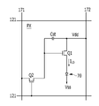
도 1은 본 발명의 일 실시예에 따른 유기 발광 표시 장치의 일 화소의 회로도이다.
도 2는 본 발명의 일 실시예에 따른 유기 발광 표시 장치의 단면도이다.
도 3은 본 발명의 일 실시예에 따른 발광 소자의 확대 단면도이다.
도 4 및 도 5는 유기 발광층에서 발생되는 발광 매커니즘을 설명하기 위한 개략적인 단면도이다.
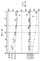
도 6은 제2 전극의 두께가 100 옹스트롬이고, 캡핑층의 두께가 830 옹스트롬인 경우, 청색 편이(blue shift) 현상을 나타낸 그래프이다.
도 7은 제2 전극의 두께가 100 옹스트롬이고, 캡핑층의 두께가 350 옹스트롬인 경우, 청색 편이(blue shift) 현상을 나타낸 그래프이다.
도 8은 제2 전극의 두께가 100 옹스트롬이고, 캡핑층의 두께가 550 옹스트롬인 경우, 청색 편이(blue shift) 현상을 나타낸 그래프이다.
도 9는 제2 전극의 두께가 100 옹스트롬이고, 캡핑층의 두께가 650 옹스트롬인 경우, 청색 편이(blue shift) 현상을 나타낸 그래프이다.1 is a circuit diagram of one pixel of an organic light emitting diode display according to an exemplary embodiment.
2 is a cross-sectional view of an organic light emitting diode display according to an exemplary embodiment.
3 is an enlarged cross-sectional view of a light emitting device according to an embodiment of the present invention.
4 and 5 are schematic cross-sectional views for explaining a light emitting mechanism generated in an organic light emitting layer.
6 is a graph illustrating a blue shift phenomenon when the thickness of the second electrode is 100 angstroms and the thickness of the capping layer is 830 angstroms.
7 is a graph illustrating a blue shift phenomenon when the thickness of the second electrode is 100 angstroms and the thickness of the capping layer is 350 angstroms.
8 is a graph illustrating a blue shift phenomenon when the thickness of the second electrode is 100 angstroms and the thickness of the capping layer is 550 angstroms.
9 is a graph illustrating a blue shift phenomenon when the thickness of the second electrode is 100 angstroms and the thickness of the capping layer is 650 angstroms.
그러면 첨부한 도면을 참고로 하여 본 발명의 실시예에 대하여 본 발명이 속하는 기술 분야에서 통상의 지식을 가진 자가 용이하게 실시할 수 있도록 상세히 설명한다. 그러나 본 발명은 여러 가지 상이한 형태로 구현될 수 있으며 여기에서 설명하는 실시예에 한정되지 않는다.Then, with reference to the accompanying drawings, embodiments of the present invention will be described in detail so that those of ordinary skill in the art to which the present invention pertains can easily implement them. However, the present invention may be embodied in several different forms and is not limited to the embodiments described herein.
도면에서 여러 층 및 영역을 명확하게 표현하기 위하여 두께를 확대하여 나타내었다. 명세서 전체를 통하여 유사한 부분에 대해서는 동일한 도면 부호를 붙였다. 층, 막, 영역, 판 등의 부분이 다른 부분 "위에" 있다고 할 때, 이는 다른 부분 "바로 위에" 있는 경우뿐만 아니라 그 중간에 또 다른 부분이 있는 경우도 포함한다. 반대로 어떤 부분이 다른 부분 "바로 위에" 있다고 할 때에는 중간에 다른 부분이 없는 것을 뜻한다. In order to clearly express various layers and regions in the drawings, the thicknesses are enlarged. Throughout the specification, like reference numerals are assigned to similar parts. When a part of a layer, film, region, plate, etc. is said to be “on” another part, it includes not only cases where it is “directly on” another part, but also cases where there is another part in between. Conversely, when we say that a part is "just above" another part, we mean that there is no other part in the middle.
우선 도 1을 참조하여 본 발명의 일 실시예에 따른 유기 발광 표시 장치의 일 화소에 대해 살펴본다. 도 1은 본 발명의 일 실시예에 따른 유기 발광 표시 장치의 일 화소의 회로도이다.First, a pixel of an organic light emitting diode display according to an exemplary embodiment will be described with reference to FIG. 1 . 1 is a circuit diagram of one pixel of an organic light emitting diode display according to an exemplary embodiment.
도 1을 참조하면, 본 발명의 일 실시예에 따른 유기 발광 표시 장치는 복수의 신호선(121, 171)과 이들에 연결되어 있으며 대략 행렬(matrix)의 형태로 배열된 복수의 화소(PX)를 포함한다.Referring to FIG. 1 , an organic light emitting diode display according to an exemplary embodiment includes a plurality of
신호선은 게이트 신호(또는 주사 신호)를 전달하는 복수의 제1 신호선(121), 데이터 신호를 전달하는 복수의 제2 신호선(171) 및 구동 전압(Vdd)을 전달하는 복수의 제3 신호선(172)을 포함한다. 제1 신호선(121)은 대략 행 방향으로 뻗어 있으며 서로가 거의 평행하고, 제2 신호선(171) 및 제3 신호선(172)은 제1 신호선(121)과 교차하여 열 방향으로 뻗어 있으며 서로가 거의 평행한다.The signal lines include a plurality of
각 화소(PX)는 스위칭 박막 트랜지스터(switching thin film transistor)(Q2), 구동 박막 트랜지스터(driving thin film transistor)(Q1), 유지 축전기(storage capacitor)(Cst) 및 유기 발광 다이오드(organic light emitting diode, OLED)(70)를 포함한다.Each pixel PX includes a switching thin film transistor Q2, a driving thin film transistor Q1, a storage capacitor Cst, and an organic light emitting diode. , OLED) (70).
스위칭 박막 트랜지스터(Q2)는 제어 단자, 입력 단자 및 출력 단자를 가지는데, 제어 단자는 제1 신호선(121)에 연결되어 있고, 입력 단자는 제2 신호선(171)에 연결되어 있으며, 출력 단자는 구동 박막 트랜지스터(Q1)에 연결되어 있다. 스위칭 박막 트랜지스터(Q2)는 제1 신호선(121)에 인가되는 주사 신호에 응답하여 제2 신호선(171)에 인가되는 데이터 신호를 구동 박막 트랜지스터(Q1)에 전달한다.The switching thin film transistor Q2 has a control terminal, an input terminal, and an output terminal. The control terminal is connected to the
구동 박막 트랜지스터(Q1) 또한 제어 단자, 입력 단자 및 출력 단자를 가지는데, 제어 단자는 스위칭 박막 트랜지스터(Q2)에 연결되어 있고, 입력 단자는 제3 신호선(172)에 연결되어 있으며, 출력 단자는 유기 발광 다이오드(70)에 연결되어 있다. 구동 박막 트랜지스터(Q1)는 제어 단자와 출력 단자 사이에 걸리는 전압에 따라 그 크기가 달라지는 출력 전류(ILD)를 흘린다.The driving thin film transistor Q1 also has a control terminal, an input terminal, and an output terminal, the control terminal is connected to the switching thin film transistor Q2, the input terminal is connected to the
축전기(Cst)는 구동 박막 트랜지스터(Q1)의 제어 단자와 입력 단자 사이에 연결되어 있다. 이 축전기(Cst)는 구동 박막 트랜지스터(Q1)의 제어 단자에 인가되는 데이터 신호를 충전하고 스위칭 박막 트랜지스터(Q2)가 턴 오프(turn-off)된 뒤에도 이를 유지한다.The capacitor Cst is connected between the control terminal and the input terminal of the driving thin film transistor Q1. The capacitor Cst charges the data signal applied to the control terminal of the driving thin film transistor Q1 and maintains it even after the switching thin film transistor Q2 is turned off.
유기 발광 다이오드(70)는 구동 박막 트랜지스터(Q1)의 출력 단자에 연결되어 있는 애노드(anode), 공통 전압(Vss)에 연결되어 있는 캐소드(cathode)를 가진다. 유기 발광 다이오드(70)는 구동 박막 트랜지스터(Q1)의 출력 전류(ILD)에 따라 세기를 달리하여 발광함으로써 영상을 표시한다.The organic
이하에서는 도 2 및 도 3을 참조하여 본 발명의 일 실시예에 따른 유기 발광 표시 장치에 대해 구체적으로 살펴본다. 도 2는 본 발명의 일 실시예에 따른 유기 발광 표시 장치의 단면도이고, 도 3은 본 발명의 일 실시예에 따른 발광 소자의 확대 단면도이다.Hereinafter, an organic light emitting diode display according to an exemplary embodiment will be described in detail with reference to FIGS. 2 and 3 . 2 is a cross-sectional view of an organic light emitting diode display according to an exemplary embodiment, and FIG. 3 is an enlarged cross-sectional view of a light emitting device according to an exemplary embodiment.
도 2 및 도 3을 참고하면, 본 발명의 일 실시예에 따른 유기 발광 표시 장치는 기판(123), 박막 트랜지스터(130), 제 1 전극(160), 제1 층(161, 162), 발광층(173), 제2 층(174, 175), 제2 전극(180), 및 캡핑층(190)을 포함한다.2 and 3 , an organic light emitting diode display according to an exemplary embodiment includes a
제1 층(161, 162)은 정공 주입층(161) 및 정공 수송층(162)을 포함할 수 있고, 제2 층(174, 175)은 전자 수송층(174) 및 전자 주입층(175)을 포함할 수 있다.The
이때, 기판(123)은 유리, 석영, 세라믹, 플라스틱 등으로 이루어진 절연성 기판으로 형성된다. 그러나, 본 발명의 일 실시예는 이에 한정되지 않고, 기판(123)은 스테인리스 강 등으로 이루어진 금속성 기판일 수도 있다.In this case, the
그리고, 기판(123) 위에는 기판 버퍼층(126)이 위치한다. 기판 버퍼층(126)은 불순 원소의 침투를 방지하며, 표면을 평탄화하는 역할을 한다.In addition, the
이때, 기판 버퍼층(126)은 상기 기능을 수행할 수 있는 다양한 물질로 형성될 수 있다. 예를 들어, 기판 버퍼층(126)은 질화 규소(SiNx)막, 산화 규소(SiOy)막, 산질화 규소(SiOxNy)막 중 어느 하나가 사용될 수 있다. 그러나, 기판 버퍼층(126)은 반드시 필요한 구성은 아니며, 기판(123)의 종류 및 공정 조건에 따라 생략될 수도 있다.In this case, the
기판 버퍼층(126) 위에는 구동 반도체층(137)이 위치한다. 구동 반도체층(137)의 재질은 다결정 규소막일 수 있다. 또한, 구동 반도체층(137)은 불순물이 도핑되지 않은 채널 영역(135), 채널 영역(135)의 양 옆으로 도핑되어 형성된 소스 영역(134) 및 드레인 영역(136)을 포함한다. 여기서, 불순물은 박막 트랜지스터의 종류에 따라 달라진다.A driving
구동 반도체층(137) 위에는 질화 규소(SiNx) 또는 산화 규소(SiOy) 따위로 형성된 게이트 절연막(127)이 위치한다. 게이트 절연막(127) 위에는 구동 게이트 전극(133)을 포함하는 게이트 배선이 위치한다. 그리고, 구동 게이트 전극(133)은 구동 반도체층(137)의 적어도 일부, 특히 채널 영역(135)와 중첩된다.A
한편, 게이트 절연막(127) 상에는 구동 게이트 전극(133)을 덮는 층간 절연막(128)이 위치한다. 게이트 절연막(127)과 층간 절연막(128)에는 구동 반도체층(137)의 소스 영역(134) 및 드레인 영역(136)을 드러내는 접촉 구멍이 위치한다. 층간 절연막(128)은, 게이트 절연막(127)과 마찬가지로, 질화 규소(SiNx) 또는 산화 규소(SiOy) 등의 세라믹(ceramic) 계열의 소재를 사용하여 만들어질 수 있다.Meanwhile, an
그리고, 층간 절연막(128) 위에는 구동 소스 전극(131) 및 구동 드레인 전극(132)을 포함하는 데이터 배선이 위치한다. 또한, 구동 소스 전극(131) 및 구동 드레인 전극(132)은 각각 층간 절연막(128) 및 게이트 절연막(127)에 형성된 접촉 구멍을 통해 구동 반도체층(137)의 소스 영역(134) 및 드레인 영역(136)과 연결된다.In addition, a data line including a driving
이와 같이, 구동 반도체층(137), 구동 게이트 전극(133), 구동 소스 전극(131) 및 구동 드레인 전극(132)을 포함하여 구동 박막 트랜지스터(130)가 형성된다. 구동 박막 트랜지스터(130)의 구성은 전술한 예에 한정되지 않고, 당해 기술 분야의 전문가가 용이하게 실시할 수 있는 공지된 구성으로 다양하게 변경 가능하다.As described above, the driving
그리고, 층간 절연막(128) 상에는 데이터 배선을 덮는 평탄화막(124)이 위치한다. 평탄화막(124)은 그 위에 형성될 유기 발광 소자의 발광 효율을 높이기 위해 단차를 없애고 평탄화시키는 역할을 한다. 또한, 평탄화막(124)은 드레인 전극(132)의 일부를 노출시키는 전극 컨택홀(122a)을 갖는다.A
평탄화막(124)은 아크릴계 수지(polyacrylates resin), 에폭시 수지(epoxy resin), 페놀 수지(phenolic resin), 폴리아미드계 수지(polyamides resin), 폴리이미드계 수지(polyimides rein), 불포화 폴리에스테르계 수지(unsaturated polyesters resin), 폴리페닐렌계 수지(poly phenylenethers resin), 폴리페닐렌설파이드계 수지(poly phenylenesulfides resin), 및 벤조사이클로부텐(benzocyclobutene, BCB) 중 하나 이상의 물질 등으로 만들 수 있다.The
여기에서, 본 발명에 따른 일 실시예는 전술한 구조에 한정되는 것은 아니며, 경우에 따라 평탄화막(124)과 층간 절연막(128) 중 어느 하나는 생략될 수도 있다.Here, an embodiment according to the present invention is not limited to the above-described structure, and in some cases, any one of the
이때, 평탄화막(124) 위에는 유기 발광 소자의 제 1 전극(160)인 애노드(160)가 위치한다.In this case, the
유기 발광 표시 장치는 복수의 화소들마다 각각 배치된 복수의 제1 전극(160)을 포함한다. 이때, 복수의 제1 전극(160)은 서로 이격 배치된다. 제1 전극(160)은 평탄화막(124)의 전극 컨택홀(122a)을 통해 드레인 전극(132)과 연결된다.The organic light emitting diode display includes a plurality of
도시하지는 않았지만, 제1 전극(160)은 투명 도전물을 포함하는 제1 투명 전극과 제2 투명 전극, 및 제1 투명 전극과 제2 투명 전극 사이에 위치하며 제2 전극(180)과 함께 미세 공진 구조(microcavity)를 형성하기 위한 반투과층을 포함할 수 있다.Although not shown, the
즉, 제1 전극(160)은 제1 투명 전극, 반투과층 및 제2 투명 전극이 순차적으로 적층된 구조를 가질 수 있으며, 제1 및 제2 투명 전극은 인듐틴옥사이드(ITO: indium tin oxide), 인듐징크옥사이드(IZO: indium zinc oxide), 징크옥사이드(ZnO: zinc oxide), 인듐옥사이드(In2O3: indium oxide), 인듐갈륨옥사이드(IGO: indium galium oxide), 및 알루미늄징크옥사이드(AZO: aluminium zinc oxide)을 포함하는 그룹에서 선택된 적어도 어느 하나를 포함할 수 있으며, 반투과층은 수 내지 수십 nm의 박막으로 형성된 Ag, Mg, Al, Pt, Pd, Au, Ni, Nd, Ir, Cr, Li, Ca, 및 Yb를 포함하는 그룹에서 선택된 적어도 하나일 수 있다.That is, the
또한, 평탄화막(124) 위에는 제1 전극(160)을 드러내는 개구부를 갖는 화소 정의막(125)이 위치한다. 즉, 화소 정의막(125)은 각 화소마다 형성된 복수개의 개구부를 갖는다. 이때, 화소 정의막(125)에 의해 형성된 개구부마다 유기 발광층(170)이 위치할 수 있다. 이에 따라, 화소 정의막(125)에 의해 각각의 유기 발광층이 형성되는 화소 영역이 정의될 수 있다.Also, a
이때, 제1 전극(160)은 화소 정의막(125)의 개구부에 대응하도록 배치된다. 그러나, 제1 전극(160)은 반드시 화소 정의막(125)의 개구부에만 배치되는 것은 아니며, 제1 전극(160)의 일부가 화소 정의막(125)과 중첩되도록 화소 정의막(125) 아래에 배치될 수 있다.In this case, the
화소 정의막(125)은 폴리아크릴계 수지(polyacrylates resin) 및 폴리이미드계(polyimides) 등의 수지 또는 실리카 계열의 무기물 등으로 만들 수 있다.The
한편, 제1 전극(160) 위에는 유기 발광층(170)이 위치한다. 유기 발광층(170)의 구조에 대해서는 하기에서 상세히 설명하기로 한다.Meanwhile, the
그리고, 유기 발광층(170) 상에는 제 2 전극(180), 즉 캐소드(180)가 위치할 수 있다. 이와 같이, 제1 전극(160), 유기 발광층(170) 및 제2 전극(180)을 포함하는 유기 발광 소자(LD)가 형성된다.In addition, the
이때, 제2 전극(180)의 재질은 은(Ag) 및 이의 합금(Ag:Yb, Ag:Mg, Ag:Al, Ag:Al:Mg 등) 중 어느 하나일 수 있으며, 복수의 층으로 형성될 수도 있다. 은(Ag)의 함량은 은(Ag) 90 vol% 이상으로 이루어질 수 있다. 은(Ag)및 이의 합금을 포함하는 제2 전극(180)은 반사율이 우수하고 광 흡수가 적어, 장치에 대해 높은 신뢰성 및 안정성을 제공할 수 있다. 또한, 제2 전극(180)의 두께는 65 옹스트롬 내지 125 옹스트롬으로 형성될 수 있다.In this case, the material of the
또한, 본 발명의 실시예에 따른 유기 발광 표시 장치는 제1 전극(160)에 반투과층을 포함하고, 제2 전극(180)은 반투과층을 포함하지 않는 전면 발광형을 예를 들어 설명하고 있으나, 본 발명이 이에 한정되는 것은 아니고 제1 전극(160) 및 제2 전극(180)을 형성하는 물질의 종류에 따라, 유기 발광 표시 장치는 배면 발광형 또는 양면 발광형도 될 수 있다.In addition, the organic light emitting diode display according to the embodiment of the present invention will be described as an example of a top emission type in which the
한편, 제2 전극(180) 위에는 제2 전극(180)을 덮어 보호하는 캡핑층(190)이 위치하고, 갭핑층(190)은 유기막 또는 무기막으로 형성될 수 있다.Meanwhile, a
캡핑층(190)의 두께는 530nm 파장에서의 광학상수 n에 대하여, (500*1.88/n) 옹스트롬 내지 (700*1.88/n) 옹스트롬으로 형성될 수 있다.The
본 발명의 일 실시예로, 캡핑층(190)의 두께는 530nm 파장에서의 광학상수 1.88에 대하여, 500 옹스트롬 내지 700 옹스트롬으로 형성될 수 있다.In an embodiment of the present invention, the
또한, 본 발명의 일 실시예로, 캡핑층(190)의 두께는 530nm 파장에서의 광학상수 2.07에 대하여, 454 옹스트롬 내지 700 옹스트롬으로 형성될 수 있다.Also, according to an embodiment of the present invention, the
또한, 본 발명의 일 실시예로, 캡핑층(190)의 두께는 530nm 파장에서의 광학상수 2.36에 대하여, 398 옹스트롬 내지 557 옹스트롬으로 형성될 수 있다.Also, according to an embodiment of the present invention, the
그리고, 캡핑층(190) 위에는 박막 봉지층(141)이 위치한다. 박막 봉지층(141)은 기판(123) 위에 위치하는 유기 발광 소자(LD)와 구동 회로부를 외부로부터 밀봉시켜 보호한다.In addition, the thin
박막 봉지층(141)은 서로 하나씩 교대로 적층되는 봉지 유기막(141a, 141c)과 봉지 무기막(141c, 141d)을 포함한다. 도 2에서는 일례로 2개의 봉지 유기막(141a, 141c)과 2개의 봉지 무기막(141c, 141d)이 하나씩 교대로 적층되어 박막 봉지층(141)을 구성하는 경우를 도시하였으나, 이에 한정되지 않는다.The thin
이제부터 도 3을 참고하여 본 발명의 유기 발광 소자에 대해서 상세하게 설명한다. 도 3은 도 2의 유기 발광 소자의 일부를 확대한 부분 단면도이다.Hereinafter, the organic light emitting device of the present invention will be described in detail with reference to FIG. 3 . 3 is an enlarged partial cross-sectional view of a portion of the organic light emitting diode of FIG. 2 .
본 발명의 일 실시예에 따른 유기 발광 소자(도 2의 X 부분)는 제 1 전극(160), 정공 주입층(161), 정공 수송층(162), 발광층(173), 전자 수송층(174), 전자 주입층(175), 제 2 전극(180), 캡핑층(190)이 순서대로 적층된 구조이다.The organic light emitting device (part X in FIG. 2 ) according to an embodiment of the present invention includes a
즉, 도 2의 유기 발광층(170)은 도 3의 정공 주입층(161), 정공 수송층(162), 발광층(173), 전자 수송층(174), 및 전자 주입층(175)을 포함한다.That is, the
이때, 정공 주입층(161)은 제 1 전극(160) 위에 위치할 수 있다. 이때, 정공 주입층(161)은 제 1 전극(160)으로부터 정공 수송층(162)으로의 정공의 주입을 개선하는 임의의 층이다. 정공 주입층(161)은 CuPc(cupper phthalocyanine), PEDOT(poly(3,4)-ethylenedioxythiophene), PANI(polyaniline), NPD(N,N-dinaphthyl-N,N'-diphenyl benzidine) 등을 포함할 수 있으나, 이에 한정되는 것은 아니다.In this case, the
정공 수송층(162)은 정공 주입층(161) 상에 위치할 수 있다. 정공 수송층(162)은 정공 주입층(161)으로부터 전달되는 정공을 원활하게 수송하는 기능을 수행할 수 있다. 예를 들면, 정공 수송층(162)은 NPD(N,N-dinaphthyl-N,N'-diphenyl benzidine), TPD(N,N'-bis-(3-methylphenyl)-N,N'-bis-(phenyl)-benzidine), s-TAD, MTDATA(4,4',4"-Tris(N-3-methylphenyl-N-phenyl-amino)-triphenylamine) 등을 포함할 수 있으나, 이에 한정되는 것은 아니다.The
본 실시예에서 정공 주입층(161)과 정공 수송층(162)이 적층된 구조를 형성하는 것으로 설명하였으나, 이에 한정되지 않고 정공 주입층(161) 및 정공 수송층(162)은 단일층으로 형성할 수도 있다.Although the present embodiment has been described as forming a structure in which the
본 명세서는 도시하지 않았으나, 정공 수송층 위에 위치하는 버퍼층(미도시)을 더 포함할 수 있다. 버퍼층은 제1 전극(160)으로부터 발광층(173)으로 전달되는 정공의 양을 조절하는 동시에, 발광층(173)으로부터 정공 수송층(162)으로 침투되는 전자의 양을 조절할 수 있다.Although not shown in the present specification, a buffer layer (not shown) positioned on the hole transport layer may be further included. The buffer layer may control the amount of holes transmitted from the
즉, 버퍼층은 정공 조절 및 전자 저지층의 역할을 하여 발광층(173)에서 정공과 전자의 결합을 도우며, 정공 수송층(162)으로 침투될 수 있는 전자를 저지하여 전자로 인한 정공 수송층(162)의 손상을 방지할 수 있다.That is, the buffer layer serves as a hole control and electron blocking layer to help the combination of holes and electrons in the
발광층(173)은 특정 색을 표시하는 발광 물질을 포함한다. 예를 들어, 발광층(173)은 청색, 녹색 또는 적색과 같은 기본색 또는 이들을 조합하는 색을 표시할 수 있다. 본 발명의 일례로써 발광층(173)은 청색 발광층, 녹색 발광층 및 적색 발광층을 포함할 수 있다.The
발광층(173)은 호스트와 도펀트를 포함한다. 발광층(173)은 적색, 녹색, 청색 및 백색을 발광하는 물질을 포함할 수 있으며, 인광 또는 형광물질을 이용하여 형성할 수 있다.The
발광층(173)이 적색을 발광하는 경우, CBP(carbazole biphenyl) 또는 mCP(1,3-bis(carbazol-9-yl)를 포함하는 호스트 물질을 포함하며, PIQIr(acac)(bis(1-phenylisoquinoline)acetylacetonate iridium), PQIr(acac)(bis(1-phenylquinoline)acetylacetonate iridium), PQIr(tris(1-phenylquinoline)iridium) 및 PtOEP(octaethylporphyrin platinum)로 이루어진 군에서 선택된 어느 하나 이상을 포함하는 도펀트를 포함하는 인광물질로 이루어질 수 있고, 이와는 달리 PBD:Eu(DBM)3(Phen) 또는 Perylene을 포함하는 형광물질로 이루어질 수 있으나 이에 한정되지 않는다.When the
발광층(173)이 녹색을 발광하는 경우, CBP 또는 mCP를 포함하는 호스트 물질을 포함하며, Ir(ppy)3(fac-tris(2-phenylpyridine)iridium)을 포함하는 도펀트 물질을 포함하는 인광물질로 이루어질 수 있고, 이와는 달리, Alq3(tris(8-hydroxyquinolino)aluminum)을 포함하는 형광물질로 이루어질 수 있으나 이에 한정되지 않는다.When the
발광층(173)이 청색을 발광하는 경우, CBP, 또는 mCP를 포함하는 호스트 물질을 포함하며, (4,6-F2ppy)2Irpic 를 포함하는 도펀트 물질을 포함하는 인광물질로 이루어질 수 있다. 이와는 달리, spiro-DPVBi, spiro-6P, 디스틸벤젠(DSB), 디스트릴아릴렌(DSA), PFO계 고분자 및 PPV계 고분자로 이루어진 군에서 선택된 어느 하나를 포함하는 형광물질로 이루어질 수 있으나 이에 한정되지 않는다.When the
한편, 전자 수송층(174)은 발광층(173) 위에 위치할 수 있다. 이때, 전자 수송층(174)은 제 2 전극(180)으로부터 발광층(173)으로 전자를 전달할 수 있다. 또한, 전자 수송층(174)은 제 1 전극(160)으로부터 주입된 정공이 발광층(173)을 통과하여 제 2 전극(180)으로 이동하는 것을 방지할 수 있다. 즉, 전자 수송층(174)은 정공 저지층의 역할을 하여, 발광층(173)에서 정공과 전자의 결합을 돕는다.Meanwhile, the
이때, 전자 수송층(174)은 Alq3(tris(8-hydroxyquinolino)aluminum), PBD, TAZ, spiro-PBD, BAlq 및 SAlq로 이루어진 군에서 선택된 어느 하나 이상으로 이루어질 수 있으나, 이에 한정되지 않는다.In this case, the
전자 수송층(174) 위에는 전자 주입층(175)이 위치한다. 전자 주입층(175)은 제2 전극(180)으로부터 전자 수송층(174)으로의 전자의 주입을 개선하는 임의의 층이다. 전자 주입층(175)은 Alq3, LiF, 갈륨 혼합물(Ga complex), PBD 등을 포함할 수 있으나, 이에 한정되는 것은 아니다.An
이하에서는 도 4 및 도 5를 참조하여 유기 발광층(170)에서 발생되는 발광 매커니즘에 대해 살펴본다. 도 4 및 도 5는 유기 발광층(170)에서 발생되는 발광 매커니즘을 설명하기 위한 개략적인 단면도이다. 도 4 및 도 5에는 제1 전극(160), 유기 발광층(170) 및 제2 전극(180)을 도시하였다.Hereinafter, a light emitting mechanism generated in the organic
먼저 도 4를 참조하면, 제1 전극(160)은 빛을 반사시키는 반사전극의 역할을 하고, 제2 전극(180)은 빛의 일부를 통과시키고, 일부를 반사시키는 반투명전극의 역할을 한다.First, referring to FIG. 4 , the
이에 따라, 유기 발광층(170)으로부터 방출된 빛의 일부는 제2 전극(180)을 통과하여 외부로 출사되고, 유기 발광층(170)으로부터 방출된 빛의 일부는 제2 전극(180)을 통과하지 못하고, 다시 제1 전극(160)으로 돌아간다.Accordingly, a portion of the light emitted from the
다시 말하면, 반사층으로 작용하는 제1 전극(160)과 제2 전극(180) 사이에서 빛은 반복적인 반사가 일어나게 되는데, 이와 같은 현상을 마이크로 캐비티(microcavity) 현상이라 한다. 즉, 빛의 광학적 공진(resonance) 현상이 일어난다.In other words, light is repeatedly reflected between the
또한, 유기 발광층(170)으로부터 방출된 빛은 출사각에 따라 파장이 변경된다. 구체적으로, 빛의 수직 성분 보다 수평 성분이 커질수록 즉, 출사각(θ)이 커질수록 파장은 짧아지고, 청색 파장 대역으로 이동된다. 사용자 관점에서 시야각이 커질수록 사용자에게 시인되는 영상의 청색 편이(blue shift) 현상이 발생된다.In addition, the wavelength of the light emitted from the organic
유기 발광층(170)으로부터 방출된 빛(S) 중에서 제2 전극(180)을 바로 통과하여 외부로 출사되는 제1 입사광(L1)의 파장 및 제2 전극(180)을 바로 통과하지 못하고, 다시 제1 전극(160)에 반사된 후 제2 전극(180)을 통과하여 외부로 출사되는 제2 입사광(L2)의 파장에 따른 공진 거리는 서로 다를 수 있다.Among the light S emitted from the organic
즉, 청색 편이(blue shift) 현상은 제2 입사광(L2)과 제1 입사광(L1)의 경로차(α-β)에 비례하여 일어날 수 있다.That is, a blue shift phenomenon may occur in proportion to a path difference α-β between the second incident light L2 and the first incident light L1 .
제2 입사광(L2)과 제1 입사광(L1)의 경로차(α-β)에 따른 위상 변화(phase shift)는 2*n*D*cos(θ)로 나타낼 수 있고, 이때 n은 유기 발광층(170)의 광학 상수이고, D는 제1 전극(160)과 제2 전극(180)의 거리이고, θ는 빛의 수직 성분에 대해 기울어진 출사각을 의미한다.A phase shift according to the path difference α-β between the second incident light L2 and the first incident light L1 may be expressed as 2*n*D*cos(θ), where n is the organic emission layer is an optical constant of (170), D is a distance between the
제2 입사광(L2)과 제1 입사광(L1)의 경로차(α-β)에 따른 위상 변화(phase shift)를 각도로 환산하면 2(2*n*D*cos(θ))/로 나타낼 수 있다. 여기서 는 빛의 파장을 의미한다.When the phase shift according to the path difference α-β between the second incident light L2 and the first incident light L1 is converted into an angle, it can be expressed as 2(2*n*D*cos(θ))/ can where is the wavelength of light.
또한, 도 5를 참조하면, 청색 편이(blue shift) 현상은 유기 발광층(170)으로부터 방출된 빛(S) 중에서 제1 전극(160)에 의해 반사된 제1 반사 위상()과 제2 전극(180)에 의해 반사된 제2 반사 위상()에 따라 달라질 수 있다.In addition, referring to FIG. 5 , the blue shift phenomenon is the first reflection phase ( ) and the second electrode ( ) reflected by the
즉, 청색 편이(blue shift)는 제2 입사광(L2)과 제1 입사광(L1)의 경로차(α-β)에 따른 위상 변화(phase shift), 제1 전극(160)에 의해 반사된 제1 반사 위상(), 및 제2 전극(180)에 의해 반사된 제2 반사 위상()에 의해 결정될 수 있고, 2(2*n*D*cos(θ))/+(+)로 표현될 수 있다.That is, the blue shift is a phase shift according to the path difference α-β between the second incident light L2 and the first incident light L1 , and the first reflected by the
이하에서는 도 6 내지 도 9를 참조하여, 제2 전극 및 캡핑층의 두께에 따른 청색 편이(blue shift) 현상이 변화되는 경향을 설명한다. 도 6은 제2 전극의 두께가 100 옹스트롬이고, 캡핑층의 두께가 830 옹스트롬인 경우, 청색 편이(blue shift) 현상을 나타낸 그래프이고, 도 7은 제2 전극의 두께가 100 옹스트롬이고, 캡핑층의 두께가 350 옹스트롬인 경우, 청색 편이(blue shift) 현상을 나타낸 그래프이고, 도 8은 제2 전극의 두께가 100 옹스트롬이고, 캡핑층의 두께가 550 옹스트롬인 경우, 청색 편이(blue shift) 현상을 나타낸 그래프이고, 도 9는 제2 전극의 두께가 100 옹스트롬이고, 캡핑층의 두께가 650 옹스트롬인 경우, 청색 편이(blue shift) 현상을 나타낸 그래프로서, 가로 축은 출사각(θ)이고, 세로 축은 위상 변화(phase shift)를 나타낸다. 이때, 캡핑층은 530nm의 파장에서의 광학상수 1.88을 가진다.Hereinafter, a change in the blue shift phenomenon according to the thickness of the second electrode and the capping layer will be described with reference to FIGS. 6 to 9 . 6 is a graph illustrating a blue shift phenomenon when the thickness of the second electrode is 100 angstroms and the thickness of the capping layer is 830 angstroms, and FIG. 7 is the thickness of the second electrode is 100 angstroms and the capping layer When the thickness of is 350 angstroms, it is a graph showing a blue shift phenomenon, and FIG. 8 is a graph showing a blue shift phenomenon when the thickness of the second electrode is 100 angstroms and the thickness of the capping layer is 550 angstroms. is a graph showing the blue shift (blue shift) when the thickness of the second electrode is 100 angstroms and the thickness of the capping layer is 650 angstroms, the horizontal axis is the emission angle (θ), the vertical axis The axis represents the phase shift. In this case, the capping layer has an optical constant of 1.88 at a wavelength of 530 nm.
먼저, 도 6을 참조하면 A선은 제2 입사광(L2)과 제1 입사광(L1)의 경로차(α-β)에 따른 위상 변화(phase shift)를 나타낸다. 제2 입사광(L2)과 제1 입사광(L1)의 경로차(α-β)에 따른 위상 변화(phase shift)는 cos(θ)에 비례하므로, 출사각(θ)이 90도로 갈수록 작아짐을 알 수 있다.First, referring to FIG. 6 , line A represents a phase shift according to the path difference α-β between the second incident light L2 and the first incident light L1 . It can be seen that since the phase shift according to the path difference α-β between the second incident light L2 and the first incident light L1 is proportional to cos(θ), the emission angle θ becomes smaller as 90 degrees. can
B선은 제2 전극(180)에 의해 반사된 제2 반사 위상()에 따른 위상 변화(phase shift)를 나타내고, C선은 제1 전극(160)에 의해 반사된 제1 반사 위상()에 따른 위상 변화(phase shift)를 나타낸다.Line B represents a phase shift according to the second reflection phase ( ) reflected by the
제1 전극(160) 및 제2 전극(180)에서 반사되는 광은 편광에 따라 수직편광성분의 광인 P파 성분과 수평편광성분의 광인 S파 성분으로 나눠지고, 제1 전극(160) 및 제2 전극(180)에서 일어나는 위상 변화(phase shift)는 P파 성분과 S파 성분의 평균에 의해 결정된다.The light reflected from the
예를 들어, 출사각(θ)이 60도를 기준으로 제2 전극(180)에서 반사되는 광의 P파 성분은 -5.82로 청색 편이(blue shift)를 감소하게 하는 성분이고, S파 성분은 16.7로 청색 편이(blue shift)를 유도하는 성분이며, 제2 반사 위상()에 따른 위상 변화(phase shift)는 P파 성분과 S파 성분의 평균인 5.43으로 청색 편이(blue shift)를 유도하게 된다.For example, the P-wave component of the light reflected from the
또한, 출사각(θ)이 60도를 기준으로 제1 전극(160)에서 반사되는 광의 P파 성분은 -7.64로 청색 편이(blue shift)를 감소시키는 성분이고, S파 성분은 12.5로 청색 편이(blue shift)를 유도하는 성분이며, 제1 반사 위상()에 따른 위상 변화(phase shift)는 P파 성분과 S파 성분의 평균인 2.43으로 청색 편이(blue shift)를 유도하게 된다.In addition, the P-wave component of the light reflected from the
D선은 2(2*n*D*cos(θ))/+(+)에 의해 결정된 전체 위상 변화(phase shift)를 나타낸다.Line D represents the total phase shift determined by 2(2*n*D*cos(θ))/+(+).
P파 성분을 고려하면, 출사각(θ)이 60도를 기준으로 제2 입사광(L2)과 제1 입사광(L1)의 경로차(α-β)에 따른 위상 변화(phase shift)인 2(2*n*D*cos(θ))/는 58.1이고, 제1 반사 위상()은 -7.64이고, 제2 반사 위상()은 -5.82임을 알 수 있다. 즉, P파 성분에 따른 전체 위상 변화(phase shift)은 58.1-(7.64+5.82)=44.6이다.Considering the P-wave component, the exit angle θ is 2 (phase shift) according to the path difference α-β between the second incident light L2 and the first incident light L1 based on 60 degrees. It can be seen that 2*n*D*cos(θ))/ is 58.1, the first reflection phase ( ) is -7.64, and the second reflection phase ( ) is -5.82. That is, the total phase shift according to the P-wave component is 58.1-(7.64+5.82)=44.6.
S파 성분을 고려하면, 출사각(θ)이 60도를 기준으로 제2 입사광(L2)과 제1 입사광(L1)의 경로차(α-β)에 따른 위상 변화(phase shift)인 2(2*n*D*cos(θ))/는 58.1이고, 제1 반사 위상()은 12.5이고, 제2 반사 위상()은 16.7임을 알 수 있다. 즉, S파 성분에 따른 전체 위상 변화(phase shift)은 58.1+(12.5+16.7)=87.3이다Considering the S-wave component, the exit angle θ is 2 (phase shift) according to the path difference α-β between the second incident light L2 and the first incident light L1 based on 60 degrees. It can be seen that 2*n*D*cos(θ))/ is 58.1, the first reflection phase ( ) is 12.5, and the second reflection phase ( ) is 16.7. That is, the total phase shift according to the S-wave component is 58.1+(12.5+16.7)=87.3
P파 성분과 S파 성분을 모두 고려한 전체 위상 변화(phase shift)는 (44.6+87.3)/2=65.9로 청색 편이(blue shift)를 유도하게 된다.The overall phase shift considering both the P-wave component and the S-wave component induces a blue shift as (44.6+87.3)/2=65.9.
이제, 도 7 내지 도 9를 참조하면, 제2 전극의 두께가 100 옹스트롬일 때, 캡핑층의 두께 변화에 따른 전체 위상 변화(phase shift)를 알 수 있다.Now, referring to FIGS. 7 to 9 , when the thickness of the second electrode is 100 angstroms, the entire phase shift according to the thickness change of the capping layer can be seen.
먼저, 도 7을 참조하면, 제2 전극의 두께는 100 옹스트롬이고, 캡핑층의 두께는 350 옹스트롬일 때, 출사각(θ)이 60도를 기준으로 P파 성분과 S파 성분을 모두 고려한 제2 반사 위상()에 따른 위상 변화(phase shift)는 10.1로 청색 편이(blue shift)를 유도하게 된다.First, referring to FIG. 7 , when the thickness of the second electrode is 100 angstroms and the thickness of the capping layer is 350 angstroms, the emission angle θ is 60 degrees, considering both the P-wave component and the S-wave component. 2 A phase shift according to the reflection phase ( ) induces a blue shift of 10.1.
이때, P파 성분과 S파 성분을 모두 고려한 전체 위상 변화(phase shift)는 (1.18+150)/2=75.6으로, 청색 편이(blue shift)를 유도하게 됨을 알 수 있다.At this time, it can be seen that the overall phase shift considering both the P-wave component and the S-wave component is (1.18+150)/2=75.6, which induces a blue shift.
다음, 도 8을 참조하면, 제2 전극의 두께는 100 옹스트롬이고, 캡핑층의 두께는 550 옹스트롬일 때, 출사각(θ)이 60도를 기준으로 P파 성분과 S파 성분을 모두 고려한 제2 반사 위상()에 따른 위상 변화(phase shift)는 -1.73으로 청색 편이(blue shift)를 감소시킨다.Next, referring to FIG. 8 , when the thickness of the second electrode is 100 angstroms and the thickness of the capping layer is 550 angstroms, the emission angle θ is 60 degrees, considering both the P-wave component and the S-wave component. 2 The phase shift according to the reflection phase ( ) reduces the blue shift to -1.73.
이때, P파 성분과 S파 성분을 모두 고려한 전체 위상 변화(phase shift)는 (28+96.1)/2=62로, 청색 편이(blue shift)를 유도하게 됨을 알 수 있다.At this time, it can be seen that the overall phase shift considering both the P-wave component and the S-wave component is (28+96.1)/2=62, which induces a blue shift.
다음, 도 9를 참조하면, 제2 전극의 두께는 100 옹스트롬이고, 캡핑층의 두께는 650 옹스트롬일 때, 출사각(θ)이 60도를 기준으로 P파 성분과 S파 성분을 모두 고려한 제2 반사 위상()에 따른 위상 변화(phase shift)는 -1.65로 청색 편이(blue shift)를 감소시킨다.Next, referring to FIG. 9 , when the thickness of the second electrode is 100 angstroms and the thickness of the capping layer is 650 angstroms, the emission angle θ is 60 degrees, considering both the P-wave component and the S-wave component. 2 The phase shift according to the reflection phase ( ) reduces the blue shift to -1.65.
이때, P파 성분과 S파 성분을 모두 고려한 전체 위상 변화(phase shift)는 (28.4+93.4)/2=60.9로, 청색 편이(blue shift)를 유도하게 됨을 알 수 있다.At this time, it can be seen that the overall phase shift considering both the P-wave component and the S-wave component is (28.4+93.4)/2=60.9, which induces a blue shift.
즉, 도 7 내지 9를 비교하면, 제2 전극의 두께는 100 옹스트롬이고 캡핑층의 두께는 550 옹스트롬일 때 제2 반사 위상()이 가장 작아 청색 편이(blue shift)를 감소시킬 수 있고, 제2 전극의 두께는 100 옹스트롬이고 캡핑층의 두께는 650 옹스트롬일 때 전체 위상 변화(phase shift)가 가장 작아 청색 편이(blue shift)를 감소시킬 수 있다는 것을 알 수 있다.That is, comparing FIGS. 7 to 9 , when the thickness of the second electrode is 100 angstroms and the thickness of the capping layer is 550 angstroms, the second reflection phase () is the smallest, so that blue shift can be reduced, It can be seen that when the thickness of the second electrode is 100 angstroms and the thickness of the capping layer is 650 angstroms, the overall phase shift is the smallest, so that blue shift can be reduced.
이와 같이, 본 발명의 일 실시예는 제2 전극의 두께는 65 옹스트롬 내지 125 옹스트롬이고, 530nm 파장에서 광학상수 1.88을 가지는 캡핑층의 두께는 500 옹스트롬 내지 700 옹스트롬으로 형성함으로써, 청색 편이(blue shift)를 감소시켜 측면 시야각을 개선할 수 있다..As such, in an embodiment of the present invention, the thickness of the second electrode is 65 angstroms to 125 angstroms, and the thickness of the capping layer having an optical constant of 1.88 at a wavelength of 530 nm is 500 angstroms to 700 angstroms. ) can be reduced to improve the lateral viewing angle.
또한, 본 발명의 다른 실시예로 제2 전극의 두께는 65 옹스트롬 내지 125 옹스트롬이고, 530nm 파장에서 광학상수 2.07을 가지는 캡핑층의 두께는 454 옹스트롬 내지 700 옹스트롬으로 형성함으로써, 청색 편이(blue shift)를 감소시켜 측면 시야각을 개선할 수 있다.In addition, in another embodiment of the present invention, the thickness of the second electrode is 65 angstroms to 125 angstroms, and the thickness of the capping layer having an optical constant of 2.07 at a wavelength of 530 nm is 454 angstroms to 700 angstroms. can be reduced to improve the lateral viewing angle.
또한, 본 발명의 또 다른 실시예로 제2 전극의 두께는 65 옹스트롬 내지 125 옹스트롬이고, 530nm 파장에서 광학상수 2.36을 가지는 캡핑층의 두께는 398 옹스트롬 내지 557 옹스트롬으로 형성함으로써, 청색 편이(blue shift)를 감소시켜 측면 시야각을 개선할 수 있다.In another embodiment of the present invention, the thickness of the second electrode is 65 angstroms to 125 angstroms, and the thickness of the capping layer having an optical constant of 2.36 at a wavelength of 530 nm is 398 angstroms to 557 angstroms. ) can be reduced to improve the lateral viewing angle.
정리하면, 본 발명의 실시예는 제2 전극의 두께는 65 옹스트롬 내지 125 옹스트롬이고, 530nm 파장에서 광학상수 n을 가지는 캡핑층의 두께는 (500*1.88/n) 옹스트롬 내지 (700*1.88/n) 옹스트롬으로 형성함으로써 청색 편이(blue shift)를 감소시켜 측면 시야각을 개선할 수 있다.In summary, in the embodiment of the present invention, the thickness of the second electrode is 65 angstroms to 125 angstroms, and the thickness of the capping layer having an optical constant n at a wavelength of 530 nm is (500*1.88/n) angstroms to (700*1.88/n) ) by reducing the blue shift (blue shift) by forming in angstroms, it is possible to improve the side viewing angle.
이상에서 본 발명의 바람직한 실시예에 대하여 상세하게 설명하였지만 본 발명의 권리범위는 이에 한정되는 것은 아니고 다음의 청구범위에서 정의하고 있는 본 발명의 기본 개념을 이용한 당업자의 여러 변형 및 개량 형태 또한 본 발명의 권리범위에 속하는 것이다.Although preferred embodiments of the present invention have been described in detail above, the scope of the present invention is not limited thereto, and various modifications and improvements by those skilled in the art using the basic concept of the present invention as defined in the following claims are also provided. is within the scope of the
123: 기판
130: 박막 트랜지스터
160: 제 1 전극
171: 정공 주입층
172: 정공 수송층 173: 발광층
174: 전자 수송층 175: 전자 주입층
180: 제 2 전극 190: 캡핑층123: substrate 130: thin film transistor
160: first electrode 171: hole injection layer
172: hole transport layer 173: light emitting layer
174: electron transport layer 175: electron injection layer
180: second electrode 190: capping layer
Claims (17)
상기 기판 위에 위치하는 박막 트랜지스터;
상기 박막 트랜지스터 위에 위치하고, 상기 박막 트랜지스터와 전기적으로 연결되어 있는 제1 전극;
제1 전극 위에 위치하는 유기 발광층;
상기 유기 발광층 위에 위치하는 제2 전극; 및
상기 제2 전극 위에 위치하는 캡핑층을 포함하고,
상기 제1 전극은,
투명 도전물을 포함하는 제1 투명 전극 및 제2 투명 전극, 및
상기 제1 투명 전극과 상기 제2 투명 사이에 위치하는 반투과층을 포함하고,
상기 제2 전극은 은(Ag)을 포함하고, 상기 제2 전극에 포함된 은(Ag)의 함량은 90 vol% 이상이고,
상기 제2 전극의 두께는 65 옹스트롬 내지 125 옹스트롬이고, 상기 캡핑층의 두께는 (500*1.88/n) 옹스트롬 내지 (700*1.88/n) 옹스트롬인 유기 발광 표시 장치:
(상기에서, n은 상기 캡핑층의 광학상수이다). Board;
a thin film transistor positioned on the substrate;
a first electrode positioned on the thin film transistor and electrically connected to the thin film transistor;
an organic light emitting layer positioned on the first electrode;
a second electrode positioned on the organic light emitting layer; and
a capping layer positioned on the second electrode;
The first electrode is
A first transparent electrode and a second transparent electrode comprising a transparent conductive material, and
a transflective layer positioned between the first transparent electrode and the second transparent;
The second electrode includes silver (Ag), and the content of silver (Ag) included in the second electrode is 90 vol% or more,
an organic light emitting diode display having a thickness of 65 angstroms to 125 angstroms, and a thickness of the capping layer in a range of (500*1.88/n) angstroms to (700*1.88/n) angstroms;
(in the above, n is the optical constant of the capping layer).
상기 n은 530nm 파장에서의 광학상수인 유기 발광 표시 장치.In claim 1,
wherein n is an optical constant at a wavelength of 530 nm.
상기 캡핑층의 광학상수는 530nm 파장에서 1.88인 유기 발광 표시 장치.In claim 2,
An optical constant of the capping layer is 1.88 at a wavelength of 530 nm.
상기 캡핑층의 두께는 500 옹스트롬 내지 700 옹스트롬인 유기 발광 표시 장치.In claim 3,
The thickness of the capping layer is 500 angstroms to 700 angstroms.
상기 캡핑층의 두께는 550 옹스트롬 내지 650 옹스트롬인 유기 발광 표시 장치.In claim 4,
The thickness of the capping layer is 550 angstroms to 650 angstroms.
상기 캡핑층의 광학상수는 530nm 파장에서 2.07인 유기 발광 표시 장치.In claim 2,
An optical constant of the capping layer is 2.07 at a wavelength of 530 nm.
상기 캡핑층의 두께는 454 옹스트롬 내지 700 옹스트롬인 유기 발광 표시 장치.In claim 6,
The thickness of the capping layer is 454 angstroms to 700 angstroms.
상기 캡핑층의 광학상수는 530nm 파장에서 광학상수는 2.36인 유기 발광 표시 장치.In claim 2,
An optical constant of the capping layer is 2.36 at a wavelength of 530 nm.
상기 캡핑층의 두께는 398 옹스트롬 내지 557 옹스트롬인 유기 발광 표시 장치.In claim 8,
The thickness of the capping layer is 398 angstroms to 557 angstroms.
상기 제2 전극은 Yb, Mg, 및 Al 중 어느 하나 이상을 더 포함하는 유기 발광 표시 장치.In claim 1,
The second electrode further includes at least one of Yb, Mg, and Al.
상기 제2 전극의 두께는 95 옹스트롬 내지 105 옹스트롬인 유기 발광 표시 장치.In claim 1,
The thickness of the second electrode is 95 angstroms to 105 angstroms.
상기 제2 전극은 반투과층을 포함하는 유기 발광 표시 장치.In claim 1,
and the second electrode includes a transflective layer.
상기 캡핑층은 유기막 또는 무기막으로 이루어진 유기 발광 표시 장치.In claim 1,
The capping layer is formed of an organic layer or an inorganic layer.
상기 유기 발광층은,
상기 제1 전극 위에 위치하는 정공 주입층 및 정공 수송층;
상기 정공 수송층 위에 위치하는 발광층; 및
상기 발광층 위에 위치하는 전자 수송층 및 전자 주입층을 포함하는 유기 발광 표시 장치.In claim 1,
The organic light emitting layer,
a hole injection layer and a hole transport layer positioned on the first electrode;
a light emitting layer positioned on the hole transport layer; and
and an electron transport layer and an electron injection layer positioned on the emission layer.
상기 제1 전극은 애노드(anode)이고,
상기 제2 전극은 캐소드(cathode)인 유기 발광 표시 장치.15. In claim 14,
The first electrode is an anode,
The second electrode is a cathode.
상기 캡핑층 위에 위치하며, 상기 기판과 합착 밀봉되어 유기 발광 소자를 밀봉시키는 박막 봉지층을 더 포함하는 유기 발광 표시 장치.In claim 1,
and a thin film encapsulation layer disposed on the capping layer and sealingly attached to the substrate to encapsulate the organic light emitting diode.
상기 제2 전극은 은(Ag) 및 Yb를 포함하고,
상기 캡핑층은 무기막으로 이루어지는 유기 발광 표시 장치.In claim 1,
The second electrode includes silver (Ag) and Yb,
The capping layer is made of an inorganic layer.
Priority Applications (1)
| Application Number | Priority Date | Filing Date | Title |
|---|---|---|---|
| KR1020220106909A KR102483892B1 (en) | 2015-06-25 | 2022-08-25 | Organic light emitting diode display |
Applications Claiming Priority (2)
| Application Number | Priority Date | Filing Date | Title |
|---|---|---|---|
| KR1020150090723A KR20170001827A (en) | 2015-06-25 | 2015-06-25 | Organic light emitting diode display |
| KR1020220106909A KR102483892B1 (en) | 2015-06-25 | 2022-08-25 | Organic light emitting diode display |
Related Parent Applications (1)
| Application Number | Title | Priority Date | Filing Date |
|---|---|---|---|
| KR1020150090723A Division KR20170001827A (en) | 2015-06-25 | 2015-06-25 | Organic light emitting diode display |
Publications (2)
| Publication Number | Publication Date |
|---|---|
| KR20220124125A true KR20220124125A (en) | 2022-09-13 |
| KR102483892B1 KR102483892B1 (en) | 2023-01-02 |
Family
ID=57602849
Family Applications (2)
| Application Number | Title | Priority Date | Filing Date |
|---|---|---|---|
| KR1020150090723A Ceased KR20170001827A (en) | 2015-06-25 | 2015-06-25 | Organic light emitting diode display |
| KR1020220106909A Active KR102483892B1 (en) | 2015-06-25 | 2022-08-25 | Organic light emitting diode display |
Family Applications Before (1)
| Application Number | Title | Priority Date | Filing Date |
|---|---|---|---|
| KR1020150090723A Ceased KR20170001827A (en) | 2015-06-25 | 2015-06-25 | Organic light emitting diode display |
Country Status (3)
| Country | Link |
|---|---|
| US (1) | US9768413B2 (en) |
| KR (2) | KR20170001827A (en) |
| CN (1) | CN106298843B (en) |
Families Citing this family (9)
| Publication number | Priority date | Publication date | Assignee | Title |
|---|---|---|---|---|
| KR102404572B1 (en) | 2017-08-04 | 2022-06-03 | 삼성디스플레이 주식회사 | Organic light emitting display apparatus |
| CN208173629U (en) * | 2017-08-16 | 2018-11-30 | 昆山国显光电有限公司 | Electrode and Organnic electroluminescent device |
| CN109686245B (en) * | 2019-02-19 | 2020-08-25 | 绵阳京东方光电科技有限公司 | Display panel and manufacturing method |
| KR102206738B1 (en) | 2019-02-27 | 2021-01-25 | 이요한 | Egi with improved reflection structure |
| CN110311051A (en) * | 2019-06-19 | 2019-10-08 | 武汉华星光电半导体显示技术有限公司 | Display panel, manufacturing method thereof, and display device |
| WO2021038475A1 (en) * | 2019-08-27 | 2021-03-04 | Oti Lumionics Inc. | Light transmissive electrode for light emitting devices |
| US11985846B2 (en) | 2020-05-13 | 2024-05-14 | Samsung Display Co., Ltd. | Display device including stacked capping layers |
| KR102666629B1 (en) | 2020-12-11 | 2024-05-27 | (주)어썸컴퍼니 | Artificial Bait for Lure Fishing |
| CN116153931B (en) * | 2021-11-19 | 2026-03-06 | 联华电子股份有限公司 | Semiconductor structure and its fabrication process |
Citations (5)
| Publication number | Priority date | Publication date | Assignee | Title |
|---|---|---|---|---|
| KR20040030359A (en) * | 2002-10-01 | 2004-04-09 | 이스트맨 코닥 캄파니 | Organic light-emitting device having enhanced light extraction efficiency |
| KR20060059068A (en) * | 2004-11-26 | 2006-06-01 | 삼성에스디아이 주식회사 | Organic electroluminescent device and manufacturing method thereof |
| KR20120052851A (en) * | 2010-11-16 | 2012-05-24 | 엘지디스플레이 주식회사 | Organic electro-luminescent device |
| KR20130065222A (en) * | 2011-12-09 | 2013-06-19 | 엘지디스플레이 주식회사 | Organic light emitting diode device |
| KR20150052490A (en) * | 2013-11-06 | 2015-05-14 | 삼성디스플레이 주식회사 | Organic light emitting diode device and manufacturing method thereof |
Family Cites Families (21)
| Publication number | Priority date | Publication date | Assignee | Title |
|---|---|---|---|---|
| ATE555506T1 (en) * | 2004-12-24 | 2012-05-15 | Cdt Oxford Ltd | LIGHT EMITTING DEVICE |
| WO2006109493A1 (en) | 2005-03-24 | 2006-10-19 | Kyocera Corporation | Luminescent element, light emitting deivce comprising said luminescent element, and process for producing the same |
| KR100683766B1 (en) * | 2005-03-30 | 2007-02-15 | 삼성에스디아이 주식회사 | Flat panel display and manufacturing method |
| JP4449846B2 (en) * | 2005-07-15 | 2010-04-14 | セイコーエプソン株式会社 | Method for manufacturing electroluminescence device |
| KR100864882B1 (en) * | 2006-12-28 | 2008-10-22 | 삼성에스디아이 주식회사 | Organic light emitting display device and manufacturing method |
| JP2008310974A (en) * | 2007-06-12 | 2008-12-25 | Casio Comput Co Ltd | Display device and manufacturing method thereof |
| KR20080111693A (en) * | 2007-06-19 | 2008-12-24 | 삼성모바일디스플레이주식회사 | Method for manufacturing polycrystalline silicon layer, thin film transistor formed using same, method for manufacturing same, and organic light emitting display device comprising the same |
| JP2009211877A (en) * | 2008-03-03 | 2009-09-17 | Sony Corp | Display device and electronic apparatus |
| JP5683094B2 (en) * | 2009-11-17 | 2015-03-11 | キヤノン株式会社 | ORGANIC ELECTROLUMINESCENCE ELEMENT AND MULTICOLOR DISPLAY DEVICE USING THE SAME |
| KR101884199B1 (en) * | 2011-06-29 | 2018-08-02 | 삼성디스플레이 주식회사 | Light emitting structure, display device including a light emitting structure and method of manufacturing a display device including a light emitting structure |
| CN102270750A (en) * | 2011-07-26 | 2011-12-07 | 昆山维信诺显示技术有限公司 | Organic electroluminescent device, display equipment and manufacture method |
| US8847216B2 (en) * | 2011-12-23 | 2014-09-30 | Lg Display Co., Ltd. | Organic light emitting display device |
| JP5425242B2 (en) * | 2012-01-31 | 2014-02-26 | キヤノン株式会社 | ORGANIC EL ELEMENT AND DISPLAY DEVICE USING THE SAME |
| KR101503313B1 (en) | 2012-08-31 | 2015-03-17 | 엘지디스플레이 주식회사 | Organic light emitting display device and method of fabricatin thereof |
| KR20140057852A (en) * | 2012-11-05 | 2014-05-14 | 삼성디스플레이 주식회사 | Organic light emitting device and manufacturing method thereof |
| KR102059940B1 (en) | 2012-11-29 | 2019-12-30 | 삼성디스플레이 주식회사 | Organic light emitting display device and manufacturing method thereof |
| KR102083982B1 (en) * | 2013-10-29 | 2020-04-16 | 삼성디스플레이 주식회사 | Organic light emitting device and manufacturing method thereof |
| KR102110918B1 (en) * | 2013-10-29 | 2020-05-14 | 엘지디스플레이 주식회사 | Organic light emitting display, method of fabricating the same |
| KR102131965B1 (en) * | 2013-11-19 | 2020-07-09 | 삼성디스플레이 주식회사 | Organic light emitting display apparatus |
| KR102296915B1 (en) * | 2014-07-30 | 2021-09-02 | 삼성디스플레이 주식회사 | organic light emitting diode display |
| US9666658B2 (en) * | 2015-01-05 | 2017-05-30 | Samsung Display Co., Ltd. | Organic light emitting diode display and manufacturing method thereof |
-
2015
- 2015-06-25 KR KR1020150090723A patent/KR20170001827A/en not_active Ceased
-
2016
- 2016-01-08 US US14/991,836 patent/US9768413B2/en active Active
- 2016-05-13 CN CN201610320050.7A patent/CN106298843B/en active Active
-
2022
- 2022-08-25 KR KR1020220106909A patent/KR102483892B1/en active Active
Patent Citations (5)
| Publication number | Priority date | Publication date | Assignee | Title |
|---|---|---|---|---|
| KR20040030359A (en) * | 2002-10-01 | 2004-04-09 | 이스트맨 코닥 캄파니 | Organic light-emitting device having enhanced light extraction efficiency |
| KR20060059068A (en) * | 2004-11-26 | 2006-06-01 | 삼성에스디아이 주식회사 | Organic electroluminescent device and manufacturing method thereof |
| KR20120052851A (en) * | 2010-11-16 | 2012-05-24 | 엘지디스플레이 주식회사 | Organic electro-luminescent device |
| KR20130065222A (en) * | 2011-12-09 | 2013-06-19 | 엘지디스플레이 주식회사 | Organic light emitting diode device |
| KR20150052490A (en) * | 2013-11-06 | 2015-05-14 | 삼성디스플레이 주식회사 | Organic light emitting diode device and manufacturing method thereof |
Also Published As
| Publication number | Publication date |
|---|---|
| KR20170001827A (en) | 2017-01-05 |
| CN106298843A (en) | 2017-01-04 |
| US9768413B2 (en) | 2017-09-19 |
| CN106298843B (en) | 2022-04-05 |
| KR102483892B1 (en) | 2023-01-02 |
| US20160380231A1 (en) | 2016-12-29 |
Similar Documents
| Publication | Publication Date | Title |
|---|---|---|
| KR102483892B1 (en) | Organic light emitting diode display | |
| US11380734B2 (en) | Organic light emitting diode display including capping layer having optical thickness for improving optics | |
| KR102490029B1 (en) | Organic light emitting diode display | |
| KR102407115B1 (en) | Organic light emitting diode display | |
| KR102525501B1 (en) | Organic light emitting display device | |
| US20170194387A1 (en) | Blue organic light emitting device and display device including the same | |
| KR102277378B1 (en) | Organic light emitting diode and organic light emitting display device including the same | |
| CN106611820B (en) | Organic Light Emitting Display Device | |
| KR102447308B1 (en) | organic light emitting diode display | |
| KR20180053140A (en) | Organic Light Emitting Diode and Organic Light Emitting Diode Display Device Including The Same | |
| US9570519B2 (en) | Organic light emitting display device with multi-organic layers | |
| KR102081248B1 (en) | Organic light emitting diode display | |
| KR102595367B1 (en) | White organic light emitting device | |
| KR102419612B1 (en) | Organic light emitting diode display | |
| KR101937999B1 (en) | Organic light emitting diode display device | |
| KR102463736B1 (en) | Organic light emitting diode and organic light emitting diode display including the same | |
| KR101731562B1 (en) | Organic light emitting diode display and manufacturing method for the same | |
| KR20170003829A (en) | Organic light emitting display device and method of manufacturing organic light emitting display device | |
| KR101822071B1 (en) | organic light emitting diode and method of manufacturing the same |
Legal Events
| Date | Code | Title | Description |
|---|---|---|---|
| A107 | Divisional application of patent | ||
| PA0107 | Divisional application |
St.27 status event code: A-0-1-A10-A18-div-PA0107 St.27 status event code: A-0-1-A10-A16-div-PA0107 |
|
| PA0201 | Request for examination |
St.27 status event code: A-1-2-D10-D11-exm-PA0201 |
|
| PG1501 | Laying open of application |
St.27 status event code: A-1-1-Q10-Q12-nap-PG1501 |
|
| E701 | Decision to grant or registration of patent right | ||
| PE0701 | Decision of registration |
St.27 status event code: A-1-2-D10-D22-exm-PE0701 |
|
| GRNT | Written decision to grant | ||
| PR0701 | Registration of establishment |
St.27 status event code: A-2-4-F10-F11-exm-PR0701 |
|
| PR1002 | Payment of registration fee |
St.27 status event code: A-2-2-U10-U11-oth-PR1002 Fee payment year number: 1 |
|
| PG1601 | Publication of registration |
St.27 status event code: A-4-4-Q10-Q13-nap-PG1601 |
|
| P22-X000 | Classification modified |
St.27 status event code: A-4-4-P10-P22-nap-X000 |
|
| P22-X000 | Classification modified |
St.27 status event code: A-4-4-P10-P22-nap-X000 |
|
| P22-X000 | Classification modified |
St.27 status event code: A-4-4-P10-P22-nap-X000 |