KR20220025419A - Battery module and battery pack including the same - Google Patents
Battery module and battery pack including the same Download PDFInfo
- Publication number
- KR20220025419A KR20220025419A KR1020200106096A KR20200106096A KR20220025419A KR 20220025419 A KR20220025419 A KR 20220025419A KR 1020200106096 A KR1020200106096 A KR 1020200106096A KR 20200106096 A KR20200106096 A KR 20200106096A KR 20220025419 A KR20220025419 A KR 20220025419A
- Authority
- KR
- South Korea
- Prior art keywords
- battery
- compression pad
- module
- cell stack
- battery cell
- Prior art date
- Legal status (The legal status is an assumption and is not a legal conclusion. Google has not performed a legal analysis and makes no representation as to the accuracy of the status listed.)
- Granted
Links
Images


Classifications
-
- H—ELECTRICITY
- H01—ELECTRIC ELEMENTS
- H01M—PROCESSES OR MEANS, e.g. BATTERIES, FOR THE DIRECT CONVERSION OF CHEMICAL ENERGY INTO ELECTRICAL ENERGY
- H01M50/00—Constructional details or processes of manufacture of the non-active parts of electrochemical cells other than fuel cells, e.g. hybrid cells
- H01M50/20—Mountings; Secondary casings or frames; Racks, modules or packs; Suspension devices; Shock absorbers; Transport or carrying devices; Holders
-
- H—ELECTRICITY
- H01—ELECTRIC ELEMENTS
- H01M—PROCESSES OR MEANS, e.g. BATTERIES, FOR THE DIRECT CONVERSION OF CHEMICAL ENERGY INTO ELECTRICAL ENERGY
- H01M10/00—Secondary cells; Manufacture thereof
- H01M10/60—Heating or cooling; Temperature control
- H01M10/62—Heating or cooling; Temperature control specially adapted for specific applications
- H01M10/625—Vehicles
-
- H—ELECTRICITY
- H01—ELECTRIC ELEMENTS
- H01M—PROCESSES OR MEANS, e.g. BATTERIES, FOR THE DIRECT CONVERSION OF CHEMICAL ENERGY INTO ELECTRICAL ENERGY
- H01M10/00—Secondary cells; Manufacture thereof
- H01M10/60—Heating or cooling; Temperature control
- H01M10/65—Means for temperature control structurally associated with the cells
- H01M10/653—Means for temperature control structurally associated with the cells characterised by electrically insulating or thermally conductive materials
-
- H—ELECTRICITY
- H01—ELECTRIC ELEMENTS
- H01M—PROCESSES OR MEANS, e.g. BATTERIES, FOR THE DIRECT CONVERSION OF CHEMICAL ENERGY INTO ELECTRICAL ENERGY
- H01M2220/00—Batteries for particular applications
- H01M2220/20—Batteries in motive systems, e.g. vehicle, ship, plane
-
- Y—GENERAL TAGGING OF NEW TECHNOLOGICAL DEVELOPMENTS; GENERAL TAGGING OF CROSS-SECTIONAL TECHNOLOGIES SPANNING OVER SEVERAL SECTIONS OF THE IPC; TECHNICAL SUBJECTS COVERED BY FORMER USPC CROSS-REFERENCE ART COLLECTIONS [XRACs] AND DIGESTS
- Y02—TECHNOLOGIES OR APPLICATIONS FOR MITIGATION OR ADAPTATION AGAINST CLIMATE CHANGE
- Y02E—REDUCTION OF GREENHOUSE GAS [GHG] EMISSIONS, RELATED TO ENERGY GENERATION, TRANSMISSION OR DISTRIBUTION
- Y02E60/00—Enabling technologies; Technologies with a potential or indirect contribution to GHG emissions mitigation
- Y02E60/10—Energy storage using batteries
Landscapes
- Chemical & Material Sciences (AREA)
- Chemical Kinetics & Catalysis (AREA)
- Electrochemistry (AREA)
- General Chemical & Material Sciences (AREA)
- Engineering & Computer Science (AREA)
- Manufacturing & Machinery (AREA)
- Battery Mounting, Suspending (AREA)
- Secondary Cells (AREA)
Abstract
Description
본 발명은 전지 모듈 및 이를 포함하는 전지팩에 관한 것으로서, 보다 상세하게는 내구성이 향상된 전지 모듈 및 이를 포함하는 전지 팩에 관한 것이다.The present invention relates to a battery module and a battery pack including the same, and more particularly, to a battery module with improved durability and a battery pack including the same.
이차 전지는 모바일 기기 및 전기 자동차 등의 다양한 제품군에서 에너지원으로 많은 관심을 받고 있다. 이러한 이차 전지는 화석 연료를 사용하는 기존 제품의 사용을 대체할 수 있는 유력한 에너지 자원으로서, 에너지 사용에 따른 부산물이 발생하지 않아 친환경 에너지원으로서 각광받고 있다.Secondary batteries are receiving a lot of attention as an energy source in various product groups such as mobile devices and electric vehicles. Such a secondary battery is a powerful energy resource that can replace the use of conventional products using fossil fuels, and is in the spotlight as an eco-friendly energy source because by-products due to energy use do not occur.
최근 이차 전지의 에너지 저장원으로서의 활용을 비롯하여 대용량 이차 전지 구조에 대한 필요성이 높아지면서, 다수의 이차 전지가 직렬/병렬로 연결된 전지 모듈을 집합시킨 멀티 모듈 구조의 전지팩에 대한 수요가 증가하고 있다.Recently, as the need for a large-capacity secondary battery structure, including the use of secondary batteries as an energy storage source, increases, the demand for a battery pack having a multi-module structure in which a plurality of secondary batteries are assembled in series/parallel connected battery pack is increasing. .
한편, 복수개의 전지셀을 직렬/병렬로 연결하여 전지팩을 구성하는 경우, 적어도 하나의 전지셀로 이루어지는 전지 모듈을 구성하고, 이러한 적어도 하나의 전지 모듈을 이용하여 기타 구성 요소를 추가하여 전지팩을 구성하는 방법이 일반적이다.On the other hand, when configuring a battery pack by connecting a plurality of battery cells in series/parallel, a battery module composed of at least one battery cell is configured, and other components are added using the at least one battery module to add other components to the battery pack. The general way to configure
이러한 전지 모듈은, 복수의 전지셀이 적층되어 있는 전지셀 적층체, 상기 전지셀 적층체를 수용하는 모듈 프레임, 상기 복수의 전지셀 사이에 배치된 압축 패드를 포함한다.The battery module includes a battery cell stack in which a plurality of battery cells are stacked, a module frame for accommodating the battery cell stack, and a compression pad disposed between the plurality of battery cells.
도 1은 종래 전지 모듈을 나타낸 단면도이다. 도 2는 도 1의 A부분을 확대한 도면이다. 도 3은 도 2의 압축 패드가 힘을 받는 부분을 표시한 도면이다.1 is a cross-sectional view showing a conventional battery module. FIG. 2 is an enlarged view of part A of FIG. 1 . FIG. 3 is a view showing a portion where the compression pad of FIG. 2 receives a force;
도 1 내지 도 3을 참조하면, 종래의 전지 모듈은, 복수의 전지셀(10)이 적층되어 있는 전지셀 적층체, 전지셀 적층체를 수용하는 모듈 프레임(20), 복수의 전지셀 사이에 배치된 압축 패드(30), 전지셀 적층체와 모듈 프레임 바닥부 사이에 형성된 열전도성 수지층(40)을 포함할 수 있다.1 to 3 , a conventional battery module includes a battery cell stack in which a plurality of
전지셀(10)들 내부의 전해액이 기화됨으로써 전지셀(10)들이 팽창하는 스웰링(Swelling) 현상이 발생할 수 있다. 스웰링 현상이 발생하면, 전지셀(10)들이 부풀어 올라 전지셀(10)들 사이에 형성된 압축 패드(30)를 가압할 수 있다.As the electrolyte solution inside the
이때 도 3에 도시된 바와 같이, 스웰링 현상으로 인해 압축 패드(30)의 양측 하단부에 응력이 집중되는 현상이 발생할 수 있다. 응력이 집중되는 압축 패드(30)의 양측 하단부는, 하측에 경화된 열전도성 수지층(40)이 자리잡고 있으며, 양측에는 전지셀(10)들이 위치할 수 있다. 이때 압축 패드(30)의 양측에 위치한 전지셀(10)들이 스웰링 되면서, 압축 패드(30)의 양측 하단부에 응력이 집중될 수 있다.At this time, as shown in FIG. 3 , a phenomenon in which stress is concentrated at both lower ends of the
압축 패드(30)의 양측 하단부에 응력이 집중될 경우, 응력이 집중된 부위가 손상될 우려가 있으며, 전지 모듈의 장기적인 사용시 모듈 내부의 내구성이 악화될 수 있다.When stress is concentrated on both lower ends of the
본 발명의 해결하고자 하는 과제는, 전지 모듈 내부의 응력 집중 부위를 삭제함으로써, 전지 모듈의 내구성을 향상시키는 전지 모듈 및 이를 포함하는 전지팩을 제공하는 것이다.SUMMARY OF THE INVENTION An object of the present invention is to provide a battery module and a battery pack including the same, which improve durability of the battery module by removing a stress concentration region inside the battery module.
본 발명의 과제들은 이상에서 언급한 과제들로 제한되지 않으며, 언급되지 않은 또 다른 과제들은 아래의 기재로부터 당업자에게 명확하게 이해될 수 있을 것이다.The problems of the present invention are not limited to the problems mentioned above, and other problems not mentioned will be clearly understood by those skilled in the art from the following description.
상기 과제를 실현하기 위한 본 발명의 일 실시예에 따른 전지 모듈은, 복수의 전지셀이 적층되어 있는 전지셀 적층체; 상기 전지셀 적층체를 수용하는 모듈 프레임; 상기 복수의 전지셀 사이에 배치된 압축 패드; 및 상기 전지셀 적층체와 상기 모듈 프레임의 바닥부 사이에 형성된 열전도성 수지층을 포함하고, 상기 압축 패드는 상기 모듈 프레임의 바닥부와 접촉하도록 형성된다.A battery module according to an embodiment of the present invention for realizing the above object includes: a battery cell stack in which a plurality of battery cells are stacked; a module frame accommodating the battery cell stack; a compression pad disposed between the plurality of battery cells; and a thermally conductive resin layer formed between the battery cell stack and the bottom of the module frame, wherein the compression pad is formed to contact the bottom of the module frame.
상기 압축 패드는 상기 모듈 프레임 바닥부와 상기 전지셀 적층체 사이 공간을 분할하고, 상기 열전도성 수지층은 상기 압축 패드로부터 분할된 공간에 각각 분할 도포될 수 있다.The compression pad may divide a space between the module frame bottom portion and the battery cell stack, and the thermally conductive resin layer may be separately applied to the space divided from the compression pad.
상기 압축 패드와 상기 복수의 전지셀은 접착 부재에 의해 고정될 수 있다.The compression pad and the plurality of battery cells may be fixed by an adhesive member.
열전도성 수지가 도포되어 형성된 상기 열전도성 수지층은 경화되어 상기 모듈 프레임과 상기 복수의 전지셀을 고정할 수 있다.The thermally conductive resin layer formed by coating the thermally conductive resin may be cured to fix the module frame and the plurality of battery cells.
상기 압축 패드는 상기 전지셀 적층체의 최외곽 전지셀과 상기 모듈 프레임의 양측면 사이에 각각 배치될 수 있다.The compression pad may be disposed between the outermost battery cell of the battery cell stack and both sides of the module frame, respectively.
상기 압축 패드는 상기 전지셀 적층체의 중앙에 배치될 수 있다.The compression pad may be disposed in the center of the battery cell stack.
상기 복수의 전지셀은 접착 부재를 통해 서로 고정될 수 있다.The plurality of battery cells may be fixed to each other through an adhesive member.
상기 복수의 전지셀은, 상기 압축 패드를 중심으로 서로 마주보는 방향으로 배치될 수 있다.The plurality of battery cells may be disposed in a direction facing each other around the compression pad.
상기 압축 패드의 하단 가운데 부분은 상기 모듈 프레임의 바닥부와 접착 부재를 통해 결합될 수 있다.A lower middle portion of the compression pad may be coupled to a bottom portion of the module frame through an adhesive member.
본 발명의 다른 일 실시예에 따른 전지 팩은 상기 전지 모듈을 포함한다.A battery pack according to another embodiment of the present invention includes the battery module.
본 발명의 일 실시예에 따른 전지 모듈 및 이를 포함하는 전지팩은, 압축 패드를 모듈 프레임 바닥부에 닿도록 연장 형성함으로써 응력 집중 부위를 삭제하고 전지 모듈의 내구성을 향상시킬 수 있는 효과를 제공한다.The battery module and the battery pack including the same according to an embodiment of the present invention provide the effect of eliminating the stress concentration area and improving the durability of the battery module by extending the compression pad to contact the bottom of the module frame .
본 발명의 효과들은 이상에서 언급한 효과들로 제한되지 않으며, 언급되지 않은 또 다른 효과들은 청구범위의 기재로부터 당업자에게 명확하게 이해될 수 있을 것이다.Effects of the present invention are not limited to the effects mentioned above, and other effects not mentioned will be clearly understood by those skilled in the art from the description of the claims.
도 1은 종래 전지 모듈을 나타낸 단면도이다.
도 2는 도 1의 A부분을 확대한 도면이다.
도 3은 도 2의 압축 패드가 힘을 받는 부분을 표시한 도면이다.
도 4는 본 발명의 일 실시예에 따른 전지 모듈을 나타낸 도면이다.
도 5는 도 4의 D-D 부분으로, 본 발명의 일 실시예에 따른 전지 모듈을 나타낸 단면도이다.
도 6은 도 5의 B 부분을 나타낸 확대도이다.
도 7은 도 6의 압축 패드가 전지셀들의 스웰링 현상에 의해 압축된 모습을 나타낸 도면이다.
도 8은 도 7의 C 부분을 확대한 도면이다.1 is a cross-sectional view showing a conventional battery module.
FIG. 2 is an enlarged view of part A of FIG. 1 .
FIG. 3 is a view showing a portion where the compression pad of FIG. 2 receives a force;
4 is a view showing a battery module according to an embodiment of the present invention.
5 is a cross-sectional view of a battery module according to an embodiment of the present invention, taken along the line DD of FIG. 4 .
6 is an enlarged view showing a portion B of FIG. 5 .
7 is a view showing a state in which the compression pad of FIG. 6 is compressed by the swelling phenomenon of the battery cells.
FIG. 8 is an enlarged view of part C of FIG. 7 .
이하에서 설명되는 실시 예는 발명의 이해를 돕기 위하여 예시적으로 나타낸 것이며, 본 발명은 여기서 설명되는 실시 예와 다르게 다양하게 변형되어 실시될 수 있음이 이해되어야 할 것이다. 다만, 본 발명을 설명함에 있어서 관련된 공지 기능 혹은 구성요소에 대한 구체적인 설명이 본 발명의 요지를 불필요하게 흐릴 수 있다고 판단되는 경우 그 상세한 설명 및 구체적인 도시를 생략한다. 또한, 첨부된 도면은 발명의 이해를 돕기 위하여 실제 축척대로 도시된 것이 아니라 일부 구성요소의 치수가 과장되게 도시될 수 있다.It should be understood that the embodiments described below are illustratively shown to help understanding of the invention, and that the present invention may be implemented with various modifications different from the embodiments described herein. However, in the description of the present invention, if it is determined that a detailed description of a related known function or component may unnecessarily obscure the gist of the present invention, the detailed description and specific illustration thereof will be omitted. In addition, the accompanying drawings are not drawn to scale in order to help understanding of the invention, but dimensions of some components may be exaggerated.
본 출원에서 사용되는 제1, 제2 용어는 다양한 구성요소들을 설명하는데 사용될 수 있지만, 구성요소들은 용어들에 의해 한정되어서는 안 된다. 용어들은 하나의 구성요소를 다른 구성요소로부터 구별하는 목적으로만 사용된다.The first and second terms used in the present application may be used to describe various components, but the components should not be limited by the terms. The terms are used only for the purpose of distinguishing one component from another.
또한, 본 출원에서 사용되는 용어는 단지 특정한 실시 예를 설명하기 위해 사용된 것으로, 권리범위를 한정하려는 의도가 아니다. 단수의 표현은 문맥상 명백하게 다르게 뜻하지 않는 한, 복수의 표현을 포함한다. 본 출원에서 "포함하다", "이루어진다" 또는 "구성되다" 등의 용어는 명세서상 기재된 특징, 숫자, 단계, 동작, 구성요소, 부품 또는 이들의 조합한 것이 존재함을 지정하려는 것이지, 하나 또는 그 이상의 다른 특징들이나 숫자, 단계, 동작, 구성요소, 부품 또는 이들의 조합한 것들의 존재 또는 부가 가능성을 미리 배제하지 않는 것으로 이해되어야 한다.In addition, the terms used in the present application are only used to describe specific embodiments, and are not intended to limit the scope of rights. The singular expression includes the plural expression unless the context clearly dictates otherwise. In the present application, terms such as "comprises", "consists of" or "consisting It should be understood that this does not preclude the possibility of addition or existence of further other features or numbers, steps, operations, components, parts, or combinations thereof.
이하, 도 4 및 도 5를 참조하여, 본 발명의 일 실시예에 따른 전지 모듈에 대해 설명한다.Hereinafter, a battery module according to an embodiment of the present invention will be described with reference to FIGS. 4 and 5 .
도 4는 본 발명의 일 실시예에 따른 전지 모듈을 나타낸 도면이다. 도 5는 도 4의 D-D 부분으로, 본 발명의 일 실시예에 따른 전지 모듈을 나타낸 단면도이다.4 is a view showing a battery module according to an embodiment of the present invention. 5 is a cross-sectional view of a battery module according to an embodiment of the present invention, taken along line D-D of FIG. 4 .
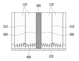
도 4 및 도 5를 참조하면, 본 발명의 일 실시예에 따른 전지 모듈은, 복수의 전지셀(110)이 적층되어 있는 전지셀 적층체(100), 전지셀 적층체(100)를 수용하는 모듈 프레임(200), 복수의 전지셀(110) 사이에 배치된 압축 패드(300) 및 전지셀 적층체(100)와 모듈 프레임(200)의 바닥부(210) 사이에 형성된 열전도성 수지층(400)을 포함한다. 압축 패드(300)는 모듈 프레임(200)의 바닥부(210)와 접촉하도록 형성된다.4 and 5 , the battery module according to an embodiment of the present invention includes a
전지셀(110)은 이차 전지로서, 파우치형 이차 전지로 구성될 수 있다. 이러한 전지셀(110)은 복수개로 구성될 수 있으며, 복수의 전지셀(110)은 상호 전기적으로 연결될 수 있도록 상호 적층되어 전지셀 적층체(100)를 형성할 수 있다. 이러한 복수개의 전지셀(110)은 각각 전극 조립체, 전지 케이스 및 전극 조립체로부터 돌출된 전극 리드를 포함할 수 있다.The
전지셀 적층체(100)는, 하부면 및 양측면을 커버하는 모듈 프레임(200) 및 상부 면을 커버하는 상부 플레이트(230)로 둘러싸여 형성된다. 이때 모듈 프레임(200) 상에 전지셀 적층체(100)가 삽입되고, 그 후 상부 플레이트(230)을 통해 전지셀 적층체의 상측면을 커버하는 방법으로 전지셀 적층체(100)가 모듈 프레임(200) 내부에 장착될 수 있다.The
모듈 프레임(200) 및 상부 플레이트(230)은 서로 결합되어 모듈 프레임(200) 내부에 위치한 전지셀 적층체(100)를 수용한다. 이때 모듈 프레임(200)과 상부 플레이트(230)는 용접을 통해 서로 결합될 수 있다. 보다 상세하게는, 모듈 프레임(200)의 양측면 상부 모서리와 상부 플레이트(230)의 양측 하면이 용접을 통해 서로 결합될 수 있다.The
전지셀 적층체(100)의 전후면에는 각각 버스바 프레임(미도시)이 형성된다. 버스바 프레임은 버스바 및 셀 연결 보드를 포함하며, 복수개의 전지셀(110)의 전극 리드들을 전기적으로 연결할 수 있도록 전지셀 적층체의 전후면을 커버하여 형성될 수 있다. 버스바 프레임의 외측에는 각각 엔드 플레이트(240)가 장착될 수 있다. 엔드 플레이트(240)는 외부의 충격으로부터 버스바 프레임에 구비된 여러 전장품을 보호하고, 동시에 버스바 프레임과 외부 전원 간의 전기적 연결을 안내할 수 있다. 엔드 플레이트(240)와 버스바 프레임 사이에는 절연 부재(미도시)가 삽입되어, 버스바 프레임과 외부와의 전기적 연결을 차단할 수 있다.A bus bar frame (not shown) is formed on the front and rear surfaces of the
도 5에 도시된 바와 같이, 복수의 전지셀(110) 사이에는 압축 패드(300)가 형성된다. 압축 패드(300)는 전지셀(110)들의 스웰링을 흡수하여 전지 모듈 내부의 내구성을 확보할 수 있다. 복수의 전지셀(110)은 압축 패드(300)를 중심으로 서로 마주보는 방향으로 배치될 수 있다. 압축 패드(300)를 중심으로 복수의 전지셀(110)들이 대칭으로 형성됨에 따라, 압축 패드(300)의 양단에 동일한 응력이 가해질 수 있다.As shown in FIG. 5 , a
전지셀 적층체(100)와 모듈 프레임(200)의 바닥부(210) 사이에는 열전도성 수지층(400)이 형성될 수 있다. 열전도성 수지층(400)은 전지셀 적층체(100)로부터 발생하는 열을 외부로 전달할 수 있다. 열전도성 수지층(400)은 모듈 프레임(200)의 바닥부(210)에 열전도성 수지가 도포되어 형성될 수 있다. 도포된 열전도성 수지는 모듈 프레임(200)에 삽입된 전지셀 적층체(100)와 바닥부(210) 사이에서 경화되어 모듈 프레임(200)과 전지셀 적층체(100)를 고정시킬 수 있다. A thermally
이하, 도 4 내지 도 8을 참조하여 본 발명의 일 실시예에 따른 압축 패드를 포함하는 전지 모듈에 대해 설명한다.Hereinafter, a battery module including a compression pad according to an embodiment of the present invention will be described with reference to FIGS. 4 to 8 .
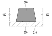
도 6은 도 5의 B 부분을 나타낸 확대도이다. 도 7은 도 6의 압축 패드가 전지셀들의 스웰링 현상에 의해 압축된 모습을 나타낸 도면이다. 도 8은 도 7의 C 부분을 확대한 도면이다.6 is an enlarged view illustrating a portion B of FIG. 5 . 7 is a view showing a state in which the compression pad of FIG. 6 is compressed by the swelling phenomenon of the battery cells. FIG. 8 is an enlarged view of part C of FIG. 7 .
본 실시예에 따르면, 압축 패드(300)는 모듈 프레임의 바닥부(210)와 접촉하도록 형성된다. 종래에는 도 3에 도시된 바와 같이 압축 패드의 하단부가 모듈 프레임의 바닥부와 이격되어 있어, 전지셀들의 스웰링에 의해 압축 패드의 양측 하단부가 스웰링되는 전지셀의 가장자리 및 열전도성 수지층과 맞닿게 되어 해당 부분에 응력이 집중되는 현상이 발생하였다. 특정 부위에 응력이 집중될 경우 전지 모듈의 내구성이 저하될 수 있다.According to this embodiment, the
이에 본 실시예에 따르면, 압축 패드(300)의 하단부가 연장되어 모듈 프레임 바닥부(210)와 접촉하도록 형성됨으로써, 도 7에 도시된 바와 같이 압축 패드(300)의 하단부에 더이상 응력이 집중되지 않아 응력 집중에 따른 내구성 저하 문제를 해결할 수 있다.Accordingly, according to this embodiment, the lower end of the
본 실시예에 따르면, 압축 패드(300)는 전지셀 적층체(100)의 중앙에 배치되어, 모듈 프레임 바닥부(210)와 전지셀 적층체(100) 사이 공간을 분할하고, 열전도성 수지는 압축 패드(300)로부터 분할된 공간에 각각 분할 도포되어 분리된 열전도성 수지층(400)이 형성될 수 있다. 열전도성 수지층(400)이 분할 도포된 모습은 도 4, 도 6 및 도 7에서 확인할 수 있다.According to this embodiment, the
열전도성 수지층(400)이 분할 도포되어 형성됨으로써, 압축 패드(300)가 위치한 방향으로 도포된 열전도성 수지가 침투할 수 있어, 열전도성 수지층(400)이 형성될 수 있는 여유 공간이 확보될 수 있다.As the thermally
도 6을 참조하면, 압축 패드(300)와 복수의 전지셀(110)은 접착 부재(500)에 의해 고정될 수 있다. 또한 복수의 전지셀(110)은 접착 부재(510)를 통해 서로 고정될 수 있다. 도 5를 참조하면, 압축 패드(310)는 전지셀 적층체(100)의 최외곽 전지셀과 모듈 프레임(200)의 양측면 사이에도 각각 배치될 수 있다.Referring to FIG. 6 , the
도 8을 참조하면, 압축 패드(300)의 하단 가운데 부분은 모듈 프레임(200)의 바닥부(210)와 접착 부재(520)를 통해 결합될 수 있다. 이를 통해 압축 패드(300)와 모듈 프레임의 바닥부(210)가 결합됨으로써 열전도성 수지의 도포로 인해 압축 패드(300)의 하단부가 일측 방향으로 쏠리지 않고 중심을 잡을 수 있다. 또한 압축 패드(300)의 하단면이 모듈 프레임의 바닥부(210)와 면대면으로 접착됨으로써 압축 패드(300)의 하단부에 작용하는 응력을 면단위로 분산시킬 수 있다.Referring to FIG. 8 , a lower middle portion of the
앞에서 설명한 전지 모듈은 전지팩에 포함될 수 있다. 전지팩은, 본 실시예에 따른 전지 모듈을 하나 이상 모아서 전지의 온도나 전압 등을 관리해 주는 전지 관리시스템(Battery Management System; BMS)과 냉각 장치 등을 추가하여 패킹한 구조일 수 있다.The battery module described above may be included in the battery pack. The battery pack may have a structure in which one or more battery modules according to the present embodiment are collected and a battery management system (BMS) that manages the temperature or voltage of the battery and a cooling device are added and packed.
상기 전지팩은 다양한 디바이스에 적용될 수 있다. 이러한 디바이스에는, 전기 자전거, 전기 자동차, 하이브리드 자동차 등의 운송 수단에 적용될 수 있으나, 본 발명은 이에 제한되지 않고 전지 모듈을 사용할 수 있는 다양한 디바이스에 적용 가능하며, 이 또한 본 발명의 권리범위에 속한다.The battery pack may be applied to various devices. Such a device may be applied to transportation means such as an electric bicycle, an electric vehicle, and a hybrid vehicle, but the present invention is not limited thereto and can be applied to various devices that can use a battery module, which also falls within the scope of the present invention .
이상에서는 본 발명의 바람직한 실시예에 대하여 도시하고 설명하였지만, 본 발명은 상술한 특정의 실시예에 한정되지 아니하며, 청구범위에서 청구하는 본 발명의 요지를 벗어남이 없이 당해 발명이 속하는 기술분야에서 통상의 지식을 가진 자에 의해 다양한 변형실시가 가능한 것은 물론이고, 이러한 변형 실시들은 본 발명의 기술적 사상이나 전망으로부터 개별적으로 이해되어서는 안될 것이다.In the above, preferred embodiments of the present invention have been illustrated and described, but the present invention is not limited to the specific embodiments described above, and it is common in the technical field to which the present invention pertains without departing from the gist of the present invention as claimed in the claims. Various modifications may be made by those having the knowledge of, of course, and these modifications should not be individually understood from the technical spirit or perspective of the present invention.
100: 전지셀 적층체
110: 전지셀
200: 모듈 프레임
210: 모듈 프레임 바닥부
300, 310: 압축 패드
400: 열전도성 수지층
500, 510, 520: 접착 부재100: battery cell stack
110: battery cell
200: module frame
210: module frame bottom
300, 310: compression pad
400: thermally conductive resin layer
500, 510, 520: adhesive member
Claims (10)
상기 전지셀 적층체를 수용하는 모듈 프레임;
상기 복수의 전지셀 사이에 배치된 압축 패드; 및
상기 전지셀 적층체와 상기 모듈 프레임의 바닥부 사이에 형성된 열전도성 수지층을 포함하고,
상기 압축 패드는 상기 모듈 프레임의 바닥부와 접촉하도록 형성되는 전지 모듈.a battery cell stack in which a plurality of battery cells are stacked;
a module frame for accommodating the battery cell stack;
a compression pad disposed between the plurality of battery cells; and
A thermally conductive resin layer formed between the battery cell stack and the bottom of the module frame,
The compression pad is a battery module formed to contact the bottom of the module frame.
상기 압축 패드는 상기 모듈 프레임 바닥부와 상기 전지셀 적층체 사이 공간을 분할하고,
상기 열전도성 수지층은 상기 압축 패드로부터 분할된 공간에 각각 분할 도포되는 전지 모듈.In claim 1,
The compression pad divides the space between the module frame bottom and the battery cell stack,
The thermally conductive resin layer is separately applied to the space divided from the compression pad battery module.
상기 압축 패드와 상기 복수의 전지셀은 접착 부재에 의해 고정되는 전지 모듈.In claim 1,
The compression pad and the plurality of battery cells are fixed by an adhesive member.
열전도성 수지가 도포되어 형성된 상기 열전도성 수지층은 경화되어 상기 모듈 프레임과 상기 복수의 전지셀을 고정하는 전지 모듈.In claim 1,
The thermally conductive resin layer formed by applying a thermally conductive resin is cured to fix the module frame and the plurality of battery cells.
상기 압축 패드는 상기 전지셀 적층체의 최외곽 전지셀과 상기 모듈 프레임의 양측면 사이에 각각 배치되는 전지 모듈.In claim 1,
The compression pad is a battery module disposed between the outermost battery cell of the battery cell stack and both sides of the module frame, respectively.
상기 압축 패드는 상기 전지셀 적층체의 중앙에 배치되는 전지 모듈.In claim 1,
The compression pad is a battery module disposed in the center of the battery cell stack.
상기 복수의 전지셀은 접착 부재를 통해 서로 고정되는 전지 모듈.In claim 1,
A battery module in which the plurality of battery cells are fixed to each other through an adhesive member.
상기 복수의 전지셀은, 상기 압축 패드를 중심으로 서로 마주보는 방향으로 배치되는 전지 모듈.In claim 1,
The plurality of battery cells are disposed in a direction facing each other with respect to the compression pad as a center.
상기 압축 패드의 하단 가운데 부분은 상기 모듈 프레임의 바닥부와 접착 부재를 통해 결합되는 전지 모듈.In claim 1,
The lower middle portion of the compression pad is coupled to the bottom of the module frame through an adhesive member.
A battery pack comprising the battery module according to claim 1 .
Priority Applications (2)
| Application Number | Priority Date | Filing Date | Title |
|---|---|---|---|
| KR1020200106096A KR102931490B1 (en) | 2020-08-24 | 2020-08-24 | Battery module and battery pack including the same |
| KR1020260031566A KR20260035165A (en) | 2020-08-24 | 2026-02-20 | Battery module and battery pack including the same |
Applications Claiming Priority (1)
| Application Number | Priority Date | Filing Date | Title |
|---|---|---|---|
| KR1020200106096A KR102931490B1 (en) | 2020-08-24 | 2020-08-24 | Battery module and battery pack including the same |
Related Child Applications (1)
| Application Number | Title | Priority Date | Filing Date |
|---|---|---|---|
| KR1020260031566A Division KR20260035165A (en) | 2020-08-24 | 2026-02-20 | Battery module and battery pack including the same |
Publications (2)
| Publication Number | Publication Date |
|---|---|
| KR20220025419A true KR20220025419A (en) | 2022-03-03 |
| KR102931490B1 KR102931490B1 (en) | 2026-02-25 |
Family
ID=80818810
Family Applications (2)
| Application Number | Title | Priority Date | Filing Date |
|---|---|---|---|
| KR1020200106096A Active KR102931490B1 (en) | 2020-08-24 | 2020-08-24 | Battery module and battery pack including the same |
| KR1020260031566A Pending KR20260035165A (en) | 2020-08-24 | 2026-02-20 | Battery module and battery pack including the same |
Family Applications After (1)
| Application Number | Title | Priority Date | Filing Date |
|---|---|---|---|
| KR1020260031566A Pending KR20260035165A (en) | 2020-08-24 | 2026-02-20 | Battery module and battery pack including the same |
Country Status (1)
| Country | Link |
|---|---|
| KR (2) | KR102931490B1 (en) |
Cited By (1)
| Publication number | Priority date | Publication date | Assignee | Title |
|---|---|---|---|---|
| WO2025110638A1 (en) * | 2023-11-20 | 2025-05-30 | 주식회사 엘지에너지솔루션 | Battery module and battery pack |
-
2020
- 2020-08-24 KR KR1020200106096A patent/KR102931490B1/en active Active
-
2026
- 2026-02-20 KR KR1020260031566A patent/KR20260035165A/en active Pending
Cited By (1)
| Publication number | Priority date | Publication date | Assignee | Title |
|---|---|---|---|---|
| WO2025110638A1 (en) * | 2023-11-20 | 2025-05-30 | 주식회사 엘지에너지솔루션 | Battery module and battery pack |
Also Published As
| Publication number | Publication date |
|---|---|
| KR20260035165A (en) | 2026-03-12 |
| KR102931490B1 (en) | 2026-02-25 |
Similar Documents
| Publication | Publication Date | Title |
|---|---|---|
| KR102503536B1 (en) | Battery module and battery pack including the same | |
| KR102754506B1 (en) | Battery module and battery pack including the same | |
| KR102473336B1 (en) | Battery module and battery pack including the same | |
| KR102754507B1 (en) | Battery pack and device including the same | |
| KR102464825B1 (en) | Battery module and battery pack including the same | |
| KR102514497B1 (en) | Battery module and battery packr including the same | |
| KR102472690B1 (en) | Battery module and battery pack including the same | |
| KR20220039302A (en) | Battery module and battery pack including the same | |
| KR20220003247A (en) | Battery pack and device including the same | |
| KR20220051709A (en) | Battery module and battery pack including the same | |
| KR20210126306A (en) | Battery module and battery pack including the same | |
| JP2021521604A (en) | Battery module including connector with shock absorbing structure | |
| KR20220060715A (en) | Battery module and battery pack including the same | |
| KR20220012045A (en) | Battery module and battery pack including the same | |
| KR102807487B1 (en) | Battery module and manufacturing method thereof | |
| KR20260035165A (en) | Battery module and battery pack including the same | |
| KR102802978B1 (en) | Battery module and battery pack including the same | |
| KR102802529B1 (en) | Battery module and battery pack including the same | |
| KR20220041429A (en) | Battery module and battery pack including the same | |
| KR20210157757A (en) | Battery pack and device including the same | |
| KR102481343B1 (en) | Battery module and battery pack including the same | |
| KR102284380B1 (en) | Battery module and battery pack including the same | |
| KR20210069426A (en) | Battery module and battery pack including the same | |
| KR20220122402A (en) | Battery module and battery pack including same | |
| KR20210080097A (en) | Battery module and battery pack including the same |
Legal Events
| Date | Code | Title | Description |
|---|---|---|---|
| PA0109 | Patent application |
St.27 status event code: A-0-1-A10-A12-nap-PA0109 |
|
| P22-X000 | Classification modified |
St.27 status event code: A-2-2-P10-P22-nap-X000 |
|
| P22-X000 | Classification modified |
St.27 status event code: A-2-2-P10-P22-nap-X000 |
|
| PN2301 | Change of applicant |
St.27 status event code: A-3-3-R10-R13-asn-PN2301 St.27 status event code: A-3-3-R10-R11-asn-PN2301 |
|
| PN2301 | Change of applicant |
St.27 status event code: A-3-3-R10-R13-asn-PN2301 St.27 status event code: A-3-3-R10-R11-asn-PN2301 |
|
| PG1501 | Laying open of application |
St.27 status event code: A-1-1-Q10-Q12-nap-PG1501 |
|
| P22-X000 | Classification modified |
St.27 status event code: A-2-2-P10-P22-nap-X000 |
|
| A201 | Request for examination | ||
| PA0201 | Request for examination |
St.27 status event code: A-1-2-D10-D11-exm-PA0201 |
|
| E902 | Notification of reason for refusal | ||
| PE0902 | Notice of grounds for rejection |
St.27 status event code: A-1-2-D10-D21-exm-PE0902 |
|
| E13-X000 | Pre-grant limitation requested |
St.27 status event code: A-2-3-E10-E13-lim-X000 |
|
| P11-X000 | Amendment of application requested |
St.27 status event code: A-2-2-P10-P11-nap-X000 |
|
| P13-X000 | Application amended |
St.27 status event code: A-2-2-P10-P13-nap-X000 |
|
| D22 | Grant of ip right intended |
Free format text: ST27 STATUS EVENT CODE: A-1-2-D10-D22-EXM-PE0701 (AS PROVIDED BY THE NATIONAL OFFICE) |
|
| PE0701 | Decision of registration |
St.27 status event code: A-1-2-D10-D22-exm-PE0701 |
|
| A16 | Divisional, continuation or continuation in part application filed |
Free format text: ST27 STATUS EVENT CODE: A-0-1-A10-A16-DIV-PA0107 (AS PROVIDED BY THE NATIONAL OFFICE) |
|
| PA0107 | Divisional application |
St.27 status event code: A-0-1-A10-A16-div-PA0107 |
|
| F11 | Ip right granted following substantive examination |
Free format text: ST27 STATUS EVENT CODE: A-2-4-F10-F11-EXM-PR0701 (AS PROVIDED BY THE NATIONAL OFFICE) |
|
| PR0701 | Registration of establishment |
St.27 status event code: A-2-4-F10-F11-exm-PR0701 |
|
| PR1002 | Payment of registration fee |
St.27 status event code: A-2-2-U10-U11-oth-PR1002 Fee payment year number: 1 |
|
| U11 | Full renewal or maintenance fee paid |
Free format text: ST27 STATUS EVENT CODE: A-2-2-U10-U11-OTH-PR1002 (AS PROVIDED BY THE NATIONAL OFFICE) Year of fee payment: 1 |
|
| PG1601 | Publication of registration |
St.27 status event code: A-4-4-Q10-Q13-nap-PG1601 |
|
| Q13 | Ip right document published |
Free format text: ST27 STATUS EVENT CODE: A-4-4-Q10-Q13-NAP-PG1601 (AS PROVIDED BY THE NATIONAL OFFICE) |